EP4130686B1 - Verfahren zur durchführung von messaufgaben und zur verwaltung von messdaten - Google Patents
Verfahren zur durchführung von messaufgaben und zur verwaltung von messdaten Download PDFInfo
- Publication number
- EP4130686B1 EP4130686B1 EP22197481.9A EP22197481A EP4130686B1 EP 4130686 B1 EP4130686 B1 EP 4130686B1 EP 22197481 A EP22197481 A EP 22197481A EP 4130686 B1 EP4130686 B1 EP 4130686B1
- Authority
- EP
- European Patent Office
- Prior art keywords
- data
- connection
- information carrier
- air conditioning
- pressure
- Prior art date
- Legal status (The legal status is an assumption and is not a legal conclusion. Google has not performed a legal analysis and makes no representation as to the accuracy of the status listed.)
- Active
Links
Images


Classifications
-
- G—PHYSICS
- G01—MEASURING; TESTING
- G01D—MEASURING NOT SPECIALLY ADAPTED FOR A SPECIFIC VARIABLE; ARRANGEMENTS FOR MEASURING TWO OR MORE VARIABLES NOT COVERED IN A SINGLE OTHER SUBCLASS; TARIFF METERING APPARATUS; MEASURING OR TESTING NOT OTHERWISE PROVIDED FOR
- G01D21/00—Measuring or testing not otherwise provided for
-
- G—PHYSICS
- G01—MEASURING; TESTING
- G01L—MEASURING FORCE, STRESS, TORQUE, WORK, MECHANICAL POWER, MECHANICAL EFFICIENCY, OR FLUID PRESSURE
- G01L19/00—Details of, or accessories for, apparatus for measuring steady or quasi-steady pressure of a fluent medium insofar as such details or accessories are not special to particular types of pressure gauges
- G01L19/08—Means for indicating or recording, e.g. for remote indication
- G01L19/12—Alarms or signals
-
- H—ELECTRICITY
- H04—ELECTRIC COMMUNICATION TECHNIQUE
- H04L—TRANSMISSION OF DIGITAL INFORMATION, e.g. TELEGRAPHIC COMMUNICATION
- H04L67/00—Network arrangements or protocols for supporting network services or applications
- H04L67/01—Protocols
- H04L67/12—Protocols specially adapted for proprietary or special-purpose networking environments, e.g. medical networks, sensor networks, networks in vehicles or remote metering networks
-
- H—ELECTRICITY
- H04—ELECTRIC COMMUNICATION TECHNIQUE
- H04W—WIRELESS COMMUNICATION NETWORKS
- H04W4/00—Services specially adapted for wireless communication networks; Facilities therefor
- H04W4/30—Services specially adapted for particular environments, situations or purposes
- H04W4/38—Services specially adapted for particular environments, situations or purposes for collecting sensor information
-
- F—MECHANICAL ENGINEERING; LIGHTING; HEATING; WEAPONS; BLASTING
- F24—HEATING; RANGES; VENTILATING
- F24F—AIR-CONDITIONING; AIR-HUMIDIFICATION; VENTILATION; USE OF AIR CURRENTS FOR SCREENING
- F24F11/00—Control or safety arrangements
- F24F11/30—Control or safety arrangements for purposes related to the operation of the system, e.g. for safety or monitoring
- F24F11/49—Control or safety arrangements for purposes related to the operation of the system, e.g. for safety or monitoring ensuring correct operation, e.g. by trial operation or configuration checks
-
- F—MECHANICAL ENGINEERING; LIGHTING; HEATING; WEAPONS; BLASTING
- F24—HEATING; RANGES; VENTILATING
- F24F—AIR-CONDITIONING; AIR-HUMIDIFICATION; VENTILATION; USE OF AIR CURRENTS FOR SCREENING
- F24F2110/00—Control inputs relating to air properties
- F24F2110/40—Pressure, e.g. wind pressure
-
- F—MECHANICAL ENGINEERING; LIGHTING; HEATING; WEAPONS; BLASTING
- F25—REFRIGERATION OR COOLING; COMBINED HEATING AND REFRIGERATION SYSTEMS; HEAT PUMP SYSTEMS; MANUFACTURE OR STORAGE OF ICE; LIQUEFACTION SOLIDIFICATION OF GASES
- F25B—REFRIGERATION MACHINES, PLANTS OR SYSTEMS; COMBINED HEATING AND REFRIGERATION SYSTEMS; HEAT PUMP SYSTEMS
- F25B2345/00—Details for charging or discharging refrigerants; Service stations therefor
- F25B2345/007—Details for charging or discharging refrigerants; Service stations therefor characterised by the weighing of refrigerant or oil
-
- F—MECHANICAL ENGINEERING; LIGHTING; HEATING; WEAPONS; BLASTING
- F25—REFRIGERATION OR COOLING; COMBINED HEATING AND REFRIGERATION SYSTEMS; HEAT PUMP SYSTEMS; MANUFACTURE OR STORAGE OF ICE; LIQUEFACTION SOLIDIFICATION OF GASES
- F25B—REFRIGERATION MACHINES, PLANTS OR SYSTEMS; COMBINED HEATING AND REFRIGERATION SYSTEMS; HEAT PUMP SYSTEMS
- F25B45/00—Arrangements for charging or discharging refrigerant
-
- H—ELECTRICITY
- H04—ELECTRIC COMMUNICATION TECHNIQUE
- H04W—WIRELESS COMMUNICATION NETWORKS
- H04W4/00—Services specially adapted for wireless communication networks; Facilities therefor
- H04W4/80—Services using short range communication, e.g. near-field communication [NFC], radio-frequency identification [RFID] or low energy communication
-
- H—ELECTRICITY
- H04—ELECTRIC COMMUNICATION TECHNIQUE
- H04W—WIRELESS COMMUNICATION NETWORKS
- H04W4/00—Services specially adapted for wireless communication networks; Facilities therefor
- H04W4/90—Services for handling of emergency or hazardous situations, e.g. earthquake and tsunami warning systems [ETWS]
Definitions
- the invention relates to a method for carrying out measurement tasks and for managing measurement data.
- Chemical industrial plants are equipped with numerous measuring points that require regular calibration. This requires comparison measurements to be taken parallel to the measuring points.
- sensors are placed in prepared reference openings or at/in service connections, and measurements are taken using the sensors.
- To track a regular measurement process over time it is advisable to record the measurement data, store it centrally, and make it available on-site.
- a wireless connection to a measuring point or a central data storage facility also simplifies handling.
- Air conditioning systems essentially consist of a circuit with two heat exchangers, a controlled expansion valve, and a pump, with the circuit filled with a refrigerant.
- the gaseous refrigerant is compressed by the pump and condenses, releasing heat, in a heat exchanger in a high-pressure (HP) section of the air conditioning system.
- HP high-pressure
- the refrigerant is expanded at the valve and absorbs heat enthalpy during evaporation in a heat exchanger in the low-pressure (LP) section of the air conditioning system, thereby cooling a medium there.
- the evaporated refrigerant in the low-pressure section of the air conditioning system is fed back to the pump.
- the refrigerant is routinely extracted using a vacuum pump, thereby also dehumidifying it.
- the air conditioning system is then filled, with the pressure in the high-pressure section and behind the expansion valve in the low-pressure section being set to specific values depending on the vapor pressure temperature of the refrigerant used.
- the efficiency of the air conditioning system depends, among other things, on these set values.
- the enthalpies can be determined from pressure and temperature measurement data in the HP and LP sections of an air conditioning system. Refrigerant-specific reference tables are used for this purpose. From the enthalpies and the electrical power consumption of the air conditioning system, an efficiency can then be calculated based on an industry-standard definition of efficiency, such as EER (Energy Efficiency Ratio) or COP (Coefficient of Performance).
- a digital service device comprising a housing, a valve block with a high-pressure connection (HP connection) and an associated valve, a low-pressure connection (LP connection) and an associated valve and a service connection, a low-pressure side temperature probe connection, a high-pressure side temperature probe connection, and an electronic evaluation unit, which is provided with and powered by a power storage device.
- the evaluation unit is connected to buttons, which are connected to internal pressure sensors that are pressure-tightly connected to the valve block.
- the evaluation unit is connected to two connections for external temperature probes and has a data memory and a display control device connected to a digital display.
- the installer can use wired temperature sensors to measure the pressure in the high-pressure and low-pressure sections of the air conditioning system.
- the WO 2010/028788 A1 A method for determining and managing data from a plurality of measuring devices is known, wherein in several measuring stations, data from one measuring device is determined and processed in a server computer unit to form client-capable data and made available. In a client station with a client computer unit, the data generated by the server computer units The data provided by the measuring stations are retrieved and further processed via a communication network.
- a method according to the invention for performing measurement tasks and managing measurement data using a system comprising at least one measuring device, at least one information carrier configured as a human-machine interface integrated into the measuring device or as a portable computer device with a screen detached from the measuring device, which information carrier is, for example, a component of the measuring device, at least one cloud server with a cloud application, and at least one user account in the cloud application.
- the measuring device and/or the information carrier are/are/is assigned to the user account.
- the measuring device and/or the information carrier are/is/are/is linked to the user account, for example, during initial login to the user account.
- the measuring device provides measurement data protocols containing measurement data received from sensors, which are assigned to the user account, and the measuring device and/or the information carrier provides further data records with the measurement data protocols. Furthermore, a computer device is provided, wherein the computer device or the information carrier is assigned to the user account, and wherein the measuring device and/or the information carrier exchange measurement data protocols and/or further data records with the computer device. For this purpose, no data connection to the cloud server is available or required, or a existing data connection to the cloud server is interrupted during the exchange.
- the cloud application also links additional data sets with the measurement data protocols.
- the functional carrier or the computer device is assigned to the user account, whereby certain storage and analysis functions on the computer device and/or the information carrier are only activated after a link or initial login with a user account on the cloud server.
- the identification of the measuring device is linked to the identification of an information carrier or computer device and to a user account on the cloud server.
- an IMEI number, a mobile phone number, and/or an email address are linked to a user and a password as a login ID.
- various systems or air conditioning systems can be or are assigned to the user account, wherein an ID number of a system or air conditioning system is stored in the user account, under which a data set with measurement data of a system or air conditioning system can be or is stored.
- a GPS position, an image, a film or a customer reference can be or is assigned to the data set of a system.
- a measuring device used in the method can comprise a housing, at least one internal sensor, an electronic control unit, at least one radio module, an operating device and an information carrier.
- the measuring device can be configured to be connected to external sensors in a wired and/or wireless manner.
- the electronic control unit is configured to convert measurement signals from internal and external sensors into digital measurement data and to provide the digital measurement data to the information carrier.
- the information carrier is configured to simultaneous availability of wired or wireless sensors, to provide and visualize either the data from the wired or the data from the wireless sensors with priority.
- the measuring or service device advantageously provides intelligent support to a technician during commissioning or maintenance of an air conditioning system by providing and/or transmitting data to the information carrier.
- the information carrier can visualize, further process, and/or analyze this data. This creates a measuring device that facilitates the commissioning and maintenance of industrial systems in the chemical industry, particularly air conditioning systems, air conditioning/refrigeration systems, and heat pumps (hereinafter collectively referred to as air conditioning systems).
- the measuring device is cost-effective and, thanks to its intelligent support, enables users to operate and connect wired and/or wireless sensors more easily and effectively.
- the radio module is designed to communicate with other devices via one or more radio technologies and/or protocols, for example according to the so-called Bluetooth standard, according to the standard of the IEEE 802.11 family, for example wireless LAN, or according to a mobile radio standard.
- the information carrier is directly connected to wireless temperature or pressure sensors that transmit measurement data to it, or indirectly connected via the electronic control unit to wireless and/or wired temperature or pressure sensors.
- the wired and/or wireless sensors transmit measurement data to the electronic control unit.
- the control unit can process, analyze, and/or transmit this data to the information carrier in processed or unprocessed form.
- the information carrier is set up to automatically provide and visualize either the data from the wired or the data from the wireless sensors with priority when connected to both wired and wireless sensors at the same time.
- providing or visualising the data, in particular measurement data, of one sensor with priority over the data of another sensor by the information carrier means, for example, that the data from the sensor given priority are processed, analysed and/or visualised on a screen by the information carrier, while the data from the other sensor are not processed, analysed and/or visualised on a screen or at least are not processed, analysed and/or visualised on a screen at the same time.
- the information carrier uses or visualizes measurement data from an external wired or wirelessly connected sensor with priority over measurement data from the internal sensor.
- the measuring device comprises a valve block.
- the valve block comprises a high-pressure connection and an associated shut-off valve for connection to a high-pressure part of an air conditioning system, a low-pressure connection and an associated shut-off valve for connection to a low-pressure part of the air conditioning system, and at least one service connection, in particular designed for connection to a compressed gas cylinder or a pump.
- the high-pressure connection and the low-pressure connection are each in pressure-tight, fluidic connection with an internal pressure sensor.
- the measuring device comprises a pressure generating device and/or a pressure regulating device.
- the information carrier is implemented as a display unit permanently connected to the measuring device and the electrical control unit.
- This display unit can be, for example, an LCD display, an LED or OLED display, or a holographic display.
- the display unit can be controlled by an optional display driver unit.
- the screen unit which is permanently connected to the measuring device and the electronic control unit, is combined with the operating device in the form of a touch display. Resistive, capacitive, and inductive touch detection are possible.
- the operating device can also be implemented by push buttons.
- this information carrier is designed, for example, as a laptop, a tablet computer, or an intelligent mobile device, also known as a smartphone.
- the portable computer device is wirelessly connected to the service device via the radio unit of the electronic control unit. Technologies and protocols according to the Bluetooth standard, the IEEE 802.11 family standard, such as wireless LAN, or a mobile communications standard are suitable for this connection.
- the portable computer device can be directly connected to wirelessly connected and/or wired sensors.
- the measuring or service device is configured in a further possible configuration to store measurement data received from connected sensors in measurement data protocols in an internal data memory of the measuring device.
- the electronic control unit is configured to receive measurement data from the wired and/or to temporarily store wirelessly connected sensors in the data storage as measurement data logs and to link them with other data sets.
- a wireless connection is established between the device and a portable computer with a screen
- the measurement data logs are automatically transferred to the portable computer.
- This function is particularly advantageous if an existing connection between the measuring or service device and a portable computer with a screen is temporarily lost during commissioning or maintenance of an air conditioning system. As soon as the connection is restored, any measurement data logs recorded in the meantime are transferred to the portable computer. The technician can then view them on the computer, ensuring no measurement information is lost.
- the measuring or service device is designed to be connected to wireless and/or wired pressure and temperature sensors.
- Pressure sensors include sensors that measure relative to the ambient pressure, as well as absolute measuring sensors and vacuum sensors.
- the service device can be equipped with plug sockets.
- Wireless sensors are powered by a battery/accumulator cell and transmit their measurement data via integrated wireless modules. This requires prior pairing with the service device.
- a function for integrating wireless sensors is started on the service device, whereupon accessible, switched-on wireless sensors are displayed on the information carrier, for example in a list, for selection. These sensors can then be selected and paired with the service device.
- these wireless sensors send an identifier to the service device, which can also be permanently assigned to specific functions. For example, a pressure sensor can be assigned for an HP function and/or display function. This identifier is then automatically recognized as such when the service device is switched on again and can then be reused for this function and/or display function.
- a wireless sensor can be provided with a color-coded identification, or it can be permanently configured as an HP or LP sensor via a hidden microswitch.
- the sensor has an internal memory in which it stores measured values and retains them in the event of a connection interruption until the connection to the service device can be reestablished.
- a status indicator such as a light or LED, to change color when a certain condition occurs, such as a low battery level or a poor or interrupted data connection.
- the wireless sensors are equipped with a rechargeable battery as a power storage unit.
- the sensors can be connected to the service device and recharged with energy from the service device's main power storage unit.
- the main power storage unit can be a rechargeable battery or consist of replaceable batteries.
- the sensors can be connected to the service device via a sensor-specific connector into which a part of the sensor can be inserted or plugged.
- a further possible design can also include bulges or protruding strips or pins on the housing of the service device, onto or around which the clips can be closed. This creates an electrical connection through which the sensor's power storage is charged.
- Wired and wireless temperature sensors can also be assigned an "HP - High Pressure” or "LP - Low Pressure” function.
- an HP temperature sensor is defined as a temperature sensor that is connected to the high-pressure section of an air conditioning system
- an LP temperature sensor is defined as a temperature sensor that is connected to the low-pressure section of an air conditioning system.
- the information carrier is configured to assign a low-pressure display function or a high-pressure display function or a negative pressure/vacuum display function to an external sensor based on an identification signal transmitted by the external sensor and/or a measuring range transmitted by the external sensor and/or the measuring signals transmitted by the external sensor.
- the information carrier is configured to display available sensors, whereby in the event of a loss of a data connection to a wired sensor, a wirelessly connectable sensor can be or is automatically assigned to the measuring device.
- the measuring or service device intelligently supports the installer in connecting and managing wired and wireless sensors by applying specific routines that depend on the sensor type and/or the configuration of the service device.
- a possible routine in this embodiment includes the service device automatically detecting a newly available wireless sensor and establishing a connection to it if there is no connection to a wired sensor with the same measurement function or if the connection to a wired sensor is interrupted. For example, if a wireless temperature sensor assigned an "HP - High Pressure" function is detected and the service device is not connected to a wired HP temperature sensor or the connection to such a wired temperature sensor is interrupted, a connection to a corresponding wireless temperature sensor is immediately established.
- Another possible routine in this embodiment includes the service device automatically establishing a connection to wireless, external pressure sensors when available, using their measurement data preferentially over measurement data from the internal pressure sensors, and visualizing it via the information carrier.
- an indicator on the information carrier signals that the data source has changed.
- This routine is based on the idea that an external pressure sensor connected directly to an air conditioning system can generally always provide more accurate measurement values for the actual pressure conditions in the air conditioning system than the sensors integrated in the service device, since there is always a hose connection between the HP or LP connection on the valve block of the service device and the air conditioning system. This hose connection could, for example, be temporarily pinched, thereby hindering pressure equalization between the air conditioning system and the service device.
- the measuring device is configured to establish a radio connection with a scale and receive weighing data from the scale.
- the scale can be loaded with a pressure vessel containing a coolant.
- the decreasing weight of the pressure vessel can be recorded by the scale, and the weight values can be transmitted to the service device.
- the information carrier can then display both the current absolute weight of the pressure vessel and the weight changes of the pressure vessel during the filling process.
- the weight change of the pressure vessel then corresponds to the amount of refrigerant being filled into the air conditioning system.
- this design has the advantage that the technician can directly monitor the weight change of the pressure vessel via the information carrier and can immediately close the shut-off valves on the valve block when the desired mass of coolant has flowed from the pressure vessel into the air conditioning system via the service connection, the valve block and the LP and/or HP connections of the valve block.
- a switching valve is provided which is connected to the measuring device in a wired or wireless manner, wherein an external sensor is configured to measure a weight and the switching valve is actuated by the measuring device when a target value of the measured weight is reached.
- the filling process can be further simplified by actuating the electrical switching valve when a previously defined threshold value of the weight change is determined by the scale or when another pressure or temperature threshold value is detected by a sensor on the air conditioning system connected to the service device.
- the measuring device receives weight data from the container and when the refrigerant is removed from the container or the container is filled with refrigerant and the threshold value of the weight of the container is reached, the switching valve closes a fluidic connection between the container and the system, in particular the air conditioning system.
- the switching valve is connected directly to the scale.
- the scale receives a command for the mass of coolant to be added to the air conditioning system via the radio connection to the service unit.
- the scale then independently controls the electric switching valve to regulate the flow of coolant into the air conditioning system.
- the switching valve is connected to the measuring or service device via a wireless connection or a cable.
- the measuring or service device then controls the electrical switching valve independently or triggered by an operator input to regulate the flow of coolant into the air conditioning system.
- an optical alarm can be understood as a signal via the information carrier or, for example, as a light on the service device lighting up or flashing.
- the electronic control unit is configured to store the amount of refrigerant removed or added when the removal of refrigerant from the container or the filling of the container with refrigerant is interrupted. Upon resumption of removal or filling, particularly after a container replacement, the electronic control unit is configured to add the amount of refrigerant removed or added from the container after the resumption to the previously stored amount of refrigerant.
- This function also known as the hold function, enables the user to fill the system with refrigerant easily, accurately, and conveniently.
- the measuring device can be calibrated with regard to its pressure sensors and/or provided with a software update.
- a software update can be installed via a memory card, e.g. an SD card, a cable connection to an external computer device, e.g. a USB cable connection, a physical data storage device, e.g. a USB data storage device, and/or a wireless connection.
- a memory card e.g. an SD card
- a cable connection to an external computer device e.g. a USB cable connection
- a physical data storage device e.g. a USB data storage device
- a wireless connection e.g. a wireless connection.
- pressure sensors can be calibrated either by correcting a zero-point signal when applying ambient pressure to the sensor, or by a two-point calibration for gauge, absolute, and vacuum sensors. Sensor calibration can also be performed by the manufacturer through characteristic curve adjustment.
- Calibration data can be stored in the service device, whereby the service device then uniquely and permanently assigns the calibration data to the pressure sensor, and/or stored in an internal memory of the pressure sensor.
- the measuring device is configured to be connected to an external server via an internet-based connection.
- the information carrier can also be configured, particularly in the form of a portable computer device, to be connected to an external server via an internet-based connection.
- the information carrier in the form of a portable computing device can also be connected via a wired connection to another computing device, such as a laptop or desktop PC.
- the other computing device is then connected to the server via the internet.
- the measuring device thus enables functionalities for the transfer and use of server-supported data to an application that can be used within a software.
- computing devices are understood to mean computing devices such as laptops, desktop PCs and other portable or stationary computing devices that are designed to establish an internet-based connection to the server.
- the measuring device is configured to determine its position using a satellite-based positioning system.
- the information carrier particularly in the form of a portable computer device, can also be configured to determine its position using a satellite-based positioning system.
- this position can be used to determine which air conditioning units are nearby.
- Data on the nearest air conditioning units can be retrieved and displayed via the information carrier.
- the measuring device is set up to read a machine-readable label attached to the air conditioning system and to identify and/or obtain data about the air conditioning system from the scanned machine-readable label.
- machine-readable marking means, for example, marking in the form of a graphic symbol, a barcode (also barcodes), a two-dimensional code (e.g. QR code, data matrix code) or a contactless chip (e.g. RFID label, NFC chip/token).
- a barcode also barcodes
- a two-dimensional code e.g. QR code, data matrix code
- a contactless chip e.g. RFID label, NFC chip/token
- the measuring device is configured to establish a radio connection with an air conditioning system if this air conditioning system has an air conditioning control and/or communication unit equipped with a radio module. Via this radio connection, data about the air conditioning system and/or protocols previously stored in the air conditioning control and/or communication unit can be transmitted to the service device and/or the information carrier.
- the measuring device is configured to store and/or retrieve protocols, in particular measurement protocols from wireless and/or wired sensors connected to the service device, as well as key data for specific systems and customers, on external servers via an internet-based connection.
- the internet-based connection can be established, for example, via mobile communications, a connection in accordance with the IEEE 802.11 family standard, e.g., wireless LAN, or LAN.
- the protocols and data stored on the external servers can also be retrieved by the technician using a portable computer or a desktop computer.
- the service device can use the protocols and data retrieved from the external servers to intelligently support the technician during maintenance and/or commissioning, for example, by visualizing measurement protocols from past maintenance calls via the information carrier and comparing them with the results of the current maintenance, or by processing and/or visualizing key data of the air conditioning system, such as the optimal refrigerant fill level and the type of refrigerant last filled, via the information carrier.
- this data can also be made available or viewed by the end customer via a portal.
- a hotel or company can have an overview of all air conditioning units with a respective "health status" that displays the following parameters: air temperature, cooling capacity, cycles, on/off status, Based on maintenance cycles and/or the calculation of the above-mentioned data, a recommendation for the next service appointment or a suggested list of a sensible order for a subsequent service technician visit can be provided.
- the service technician can also make all reports, including invoices and other data, available via this portal.
- the measuring device in another possible design, it includes a lockable device to protect against theft, or eyelets are integrated into the housing of the measuring or service device through which the measuring or service device can be secured with a lock.
- the measuring device can be connected to at least two or at least four wireless and/or wired temperature sensors and to at least one or at least two external wireless and/or wired pressure sensors, and the measuring or service device receives and processes the measurement data of all of these sensors simultaneously or sequentially.
- the service device accesses, for example, refrigerant-specific auxiliary tables stored in the service device's data memory. For example, upon request from the technician, the service device processes the received sensor data and, using the refrigerant-specific auxiliary tables, calculates the efficiency of an air conditioning system and outputs this value via the information carrier.
- Refrigerant-specific auxiliary tables are understood to mean, in particular, tables which contain specific enthalpy values of the refrigerant, divided at least according to pressure and temperature.
- the measuring device simplifies and/or improves the maintenance and commissioning of air conditioning systems by improving several sub-steps of commissioning and/or maintenance of an air conditioning system through new procedures that utilize the measuring or service device.
- Such sub-steps include, for example, checking the air conditioning system for leaks, measuring the air conditioning system's temperature, and determining the air conditioning system's efficiency.
- This procedure offers the technician the advantage that the test can be carried out in a short time and the technician can use either the determined time t2 or the determined pressure limit value at time t3 as a guideline to decide when the next maintenance of the system should be carried out at the latest.
- a leakage rate can be analyzed as an important parameter of the system to determine whether the system may be operated.
- the technician In order for the service device to determine an absolute leakage rate, the technician must enter a parameter for the internal volume of the air conditioning system.
- this overpressure leak test method also offers the technician the advantage that the test can be carried out in a short time, and the technician can use either the determined time t2 or the determined pressure limit value at time t3 as a guideline to decide when the next maintenance of the system should be carried out at the latest.
- the extrapolation of the measurement data and the calculation of certain characteristic values in both leak testing procedures can be carried out directly by the measuring or service device or the information carrier.
- This improved method for temperature measurement provides the installer with the advantage that a temperature measurement error due to a temperature gradient between an inside of a pipe, which is in thermal contact with the refrigerant, and an outside of the pipe, which is in thermal contact with the ambient air, can be eliminated and thus an actual real temperature of the refrigerant in the air conditioning system can be determined more accurately.
- the service device in the described procedure uses, for example, predefined material properties and geometry data for the pipeline that correspond to industry standard values.
- the temperature measurement on the air conditioning system's pipes is improved using the measured surface temperature of the pipe and the measured ambient temperature in that the fitter can enter specific material properties and/or geometry data of the pipe, so that the service device calculates a real temperature of the refrigerant in the pipe taking these specific data into account and outputs it via the information carrier.
- Assigning the corresponding functions to the respective sensors means, for example, that the technician configures on the service device or the information carrier which sensor is installed at which measuring position.
- the information carrier displays an identifier or label for each connected sensor to the technician, allowing the technician to clearly identify which sensor on the service device to enter the selected function, i.e., the selected measurement position. This is done for all connected sensors.
- FIG. 1A A system 60 for carrying out measurement tasks and managing measurement data is shown.
- the system 60 comprises a measuring device 1, hereinafter also referred to as service device 1, which is described in more detail in the following figures using various exemplary embodiments.
- the measuring device 1 is coupled to a system or an air conditioning system 2 and comprises internal sensors for detecting a pressure P1 and a temperature T1 of a medium carried in the system or refrigerant carried in the air conditioning system 2.
- the measuring device 1 comprises an information carrier 15 with a screen unit 20.
- the measuring device 1 can also be coupled to an information carrier 15 designed as a portable computer device 21, which comprises a screen 22.
- the information carrier 15 is configured to provide and visualize either the data of the wired or the data of the wirelessly connected sensors with priority when wired or wirelessly connected sensors are simultaneously available, in this case for example an external, wireless pressure sensor 18 and an external, wireless temperature sensor 16.
- a second pressure P2 is determined using the wireless pressure sensor 18.
- a second temperature T2 is determined using the wireless temperature sensor 18.
- the pressure P2 and the temperature T2 are transmitted via a wireless connection from the external pressure sensor 18 and the external temperature sensor 16, respectively, to the information carrier 15.
- the information carrier 15 is configured to display available sensors, whereby in case of loss of a data connection to a wired sensor, a wirelessly connectable sensor is automatically assigned to the measuring device 1.
- the information carrier 15 is designed to use or visualize measurement data from an external wired or wirelessly connected sensor with priority over measurement data from the internal sensor.
- the information carrier 15 recognizes an external sensor on the basis of an identification signal transmitted by the external sensor and/or a measuring range transmitted by the external sensor and/or assigns a low-pressure display function or a high-pressure display function or a negative pressure/vacuum display function to the measuring signals transmitted by the external sensor.
- the data from the sensor given priority are processed, analyzed and/or visualized on the screen 22 by the information carrier 15, while the data from the other sensor are not processed, analyzed and/or visualized on the screen 22 or at least are not processed, analyzed and/or visualized on the screen 22 at the same time.
- the measuring device 1 is connected to a cloud server 44 via an internet-based connection 43.
- the cloud server 44 comprises a cloud application and at least one Figure 1D
- the user account 53 in the cloud application is shown in more detail.
- the measuring device 1 and/or the information carrier 15 are/will be assigned to the user account 53.
- the measuring device 1 provides measurement data protocols with the pressures P1 and/or P2 and the temperatures T1 and/or T2 that are assigned to the user account 53.
- the measuring device 1 and/or the information carrier 15 and/or the cloud application can provide further Figure 1D link the data records 54 shown in more detail with the measurement data protocols.
- the computer device 21 or the information carrier 15 are assigned to the user account 53, wherein the measuring device 1 and/or the information carrier 15 exchange measurement data protocols and/or further data records 54 with the computer device 21, wherein no data connection to the cloud server 44 is required for this exchange or an existing data connection to the cloud server 44 is interrupted during the exchange.
- an identification of the measuring device 1 is linked with an identification of the information carrier 15 and/or the computer device 21 and with a user account 53 on the cloud server 44, whereby an IMEI number, a mobile phone number and/or an email address with a Figure 1D be or will be linked to the user B described in more detail and a password.
- various systems or air conditioning systems 2 can be assigned or are assigned to the user account 53, wherein an ID number of a system or air conditioning system 2 is stored in the user account 53, under which a data record 54 with measurement data of a system or air conditioning system 2 can be stored or is stored.
- a GPS position, an image, a film or a customer reference can be assigned or is assigned to the data record 54 of a system or air conditioning system 2.
- the system 60 comprises a satellite-based positioning system 50. Both the air conditioning system 2 and the information carrier 15 can be connected to this satellite-based positioning system 50 and thus determine their geo-positions and transmit them together with the data sets to the cloud server 44.
- Additional computing devices 47 can also be connected to the cloud server 44 via the internet-based connection 43.
- the cloud server 44 provides these devices with information, such as system data and measurement protocols 51, which can be retrieved and displayed by the computing devices 47.
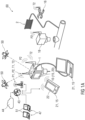
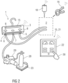
- Figure 1B shows a possible arrangement of a measuring device 1 (service device 1), a system 2 or air conditioning system 2 and a pump 29, which can be coupled to the measuring device 1.
- a pressure sensor 19 is shown, which can be connected to the measuring device 1 via a cable connection 52.
- the connection 52 can also be designed as a media socket, for example, for current and voltage.
- the measuring device 1 comprises a housing 3, a high pressure/HP connection 5, a low pressure/LP connection 6 and a service connection 7 as well as an electronic Control unit 10 and/or optionally a portable computer device 21 with a screen 22 as a further information carrier 15.
- a hose connection connects the high pressure/HP connection 5 with the HP part of system 2.
- Another hose connection connects the low pressure/LP connection 6 with the LP part of system 2.
- the service connection 7 can be connected to an inlet of the pump 29.
- the measuring device 1 may further comprise a pressure generating device 61, which is implemented, for example, by a hand-operated pump or an electric pump.
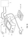
- FIG. 1C a possible embodiment of an intelligent service device 1 during maintenance or commissioning of an air conditioning system 2 is shown.
- the service device 1 is shown with a housing 3, a valve block 4, a high pressure/HP connection 5, a low pressure/LP connection 6, a service connection 7, two shut-off valves 8, several buttons as operating device 13, a display unit 20 as information carrier 15, a portable computer device 21 with a display 22 as further information carrier 15, two external wireless temperature sensors 16, an external wireless pressure sensor 18, a wired pressure sensor 19 and three connected hose connections.
- a hose connection connects the high pressure/HP port 5 to the HP part of the air conditioning system 2 by being connected to a piping at the outlet of a compressor 30.
- Another hose connection connects the low pressure/LP connection 6 to the LP part of the air conditioning system 2 by connecting it to the piping at the inlet of the compressor 30.
- Another hose connection connects the service connection 7 to an inlet of a pump 29, which in turn is connected to a compressed gas cylinder 28, the compressed gas cylinder 28 being on a scale 23.
- the air conditioning system 2 is represented by the main components compressor 30, condenser 31, expansion valve 32, and evaporator 33.
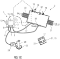
- Figure 1D shows an arrangement of a measuring device 1 (service device 1), an air conditioning system 2 and a cloud server during commissioning or maintenance of an air conditioning system 2.
- the measuring device 1 is connected to the cloud server 44 via the internet-based connection 43.
- the cloud server 44 comprises the cloud application and at least one user account 53 in the cloud application.
- the measuring device 1 and/or the information carrier 15 are assigned to the user account 53.
- the measuring device 1 provides measurement data protocols in the form of data sets 54 that are assigned to the user account 53.
- the measuring device 1 and/or the information carrier 15 and/or the cloud application can link further data sets 54 to the measurement data protocols.
- various systems or air conditioning systems 2 can be assigned or are assigned to the user account 53, wherein an ID number of a system or air conditioning system 2 is stored in the user account 53, under which a data record 54 with measurement data of a system or air conditioning system 2 can be stored or is stored.
- a GPS position, an image, a film or a customer reference can be assigned or is assigned to the data record 54 of a system or air conditioning system 2.
- the service device 1 is provided with a housing 3, a valve block 4, a high pressure/HP connection 5, a low pressure/LP connection 6, a service connection 7, two shut-off valves 8, an information carrier 15, a portable computer device 21 with a screen 22 as a further information carrier 15, an external, wireless Temperature sensor 16, an external, wireless pressure sensor 18 and three connected hose connections.
- a hose connection connects the high pressure/HP connection 5 to the HP part of the air conditioning system 2.
- Another hose connection connects the low pressure/LP connection 6 to the LP part of the air conditioning system 2.
- Another hose connection connects the service connection 7 to the inlet of a pump 29, which in turn is connected to a compressed gas cylinder 28, the compressed gas cylinder 28 being on a scale 23.
- the air conditioning system 2 is schematically indicated by a dashed frame.
- an operator input by touch 39 is schematically indicated.
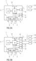
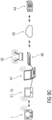
- FIG 3A A possible design of the intelligent service device 1 is shown schematically.
- the service device 1 is shown with a housing 3, a valve block 4, a high-pressure/HP connection 5, a low-pressure/LP connection 6, a service connection 7, two shut-off valves 8, two internal pressure sensors 9, an electronic control unit 10, a main power storage unit 11, a data storage unit 12, an operating device 13, a radio module 14, an information carrier 15, an external wireless temperature sensor 16, and an external wireless pressure sensor 18.
- the service device 1 is in radio communication with the wireless sensors 16, 18 shown via its radio module 14.
- FIG 3B Another possible embodiment of the intelligent service device 1 is shown schematically.
- FIG 4A Another possible embodiment of the intelligent service device 1 is shown schematically.
- the service device 1 is shown with a housing 3, a valve block 4, a high-pressure/HP port 5, a low-pressure/LP port 6, a service port 7, two shut-off valves 8, two internal pressure sensors 9, an electronic control unit 10, a main power storage unit 11, a data storage unit 12, an operating device 13, a radio module 14, an external wireless temperature sensor 16, an external wireless pressure sensor 18, and an external portable computing device 21 with a screen 22.
- the service device 1 is in radio communication with the wireless sensors 16, 18 shown, as well as with the portable computing device 21, via its radio module 14.
- FIG 4B A further possible embodiment of the intelligent service device 1 is shown schematically.
- the service device 1 is shown in Figure 4B with two cable connections 35, a wired temperature sensor 17 and a wired pressure sensor 19.
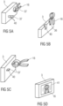
- an external, wireless temperature sensor 16 can be connected to a housing 3, for example, so that an internal power storage of the wireless temperature sensor 16 is connected to electrical charging contacts 40 on the housing 3 and can be charged via it.
- FIG 5A The housing 3 is shown with cylindrical or conical protrusions 37, around which a wireless temperature sensor 16 can be clamped in a clamp design.
- the electrical charging contacts 40 are shown as elements arranged in a ring on the outer surface of the protrusion 37.
- FIG. 5B The housing 3 is shown with sensor couplings 36, around which a wireless temperature sensor 16, but also another sensor, can be inserted or plugged in.
- the electrical charging contacts 40 are shown as exemplary contact points on a bottom surface of the sensor coupling 36.
- FIG. 5C The housing 3 is shown with rectangular protrusions 37, to which a wireless temperature sensor 16 in clamp design can be clamped. Electrical charging contacts 40 are shown as examples as contact points on the outer surface of the bulge 37.
- FIG. 5D The housing 3 is shown with a contactless charging surface 41, to which a wireless temperature sensor 16 or another wireless sensor can be placed or applied. Charging is achieved by contactless charging, e.g., via inductive energy transfer.
- the high pressure/HP connection 5 and the low pressure/LP connection 6 of the service device 1 are connected to an air conditioning system 2 via hose connections.
- the compressed gas cylinder 28 stands on a scale 23.
- the scale 23 and the service device 1 are connected wirelessly.
- the electrical switching valve 24 is connected to the scale 23 via a cable.
- the high pressure/HP port 5 and the low pressure/LP port 6 of the service unit 1 are connected to an air conditioning system 2 via hose connections.
- the compressed gas cylinder 28 is located on a scale 23.
- the scale 23 and the service device 1 are radio-connected.
- the electrical switching valve 24 is also radio-connected to the service device 1 and/or the scale 23.
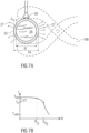
- FIG. 7A a pipe 25 for a refrigerant 26 is shown in cross section.
- a sensor head of a temperature sensor 38 is in thermal contact with an outer surface of the pipeline 25.
- Geometric data of the pipeline 25 are qualitatively represented by an outer diameter Da, an inner diameter di and a wall thickness s.
- Figure 7B is qualitatively a temperature curve from the middle of the pipe 25 according to Figure 7A plotted over the radius.
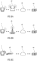
- Figure 8A schematically shows a possible embodiment of a communication arrangement in which a possible embodiment of the intelligent service device 1 is or will be connected to a server 44 via a WLAN router 42 and an internet-based connection 43.
- the service device 1 is in wireless connection with the WLAN router 42.
- the WLAN router 42 is in an internet-based connection 43 with the server 44, for example via a cable.
- FIG 8B A further possible embodiment of a communication arrangement is shown schematically, in which a possible embodiment of the intelligent service device 1 is or will be connected to a server 44 via a mobile radio connection to a mobile radio mast 45 and an internet-based connection 43.
- FIG 8C A further possible embodiment of a communication arrangement is shown schematically, in which a possible embodiment of the intelligent service device 1 is or will be connected to a server 44 via a router 46 and an internet-based connection 43.
- FIG 9A A further possible embodiment of a communication arrangement is shown schematically, in which a possible embodiment of the intelligent service device 1 is in radio connection with a portable computer device 21 as information carrier 15 and the portable computer device 21, 15 is or will be connected to a server 44 via a WLAN router 42 and an internet-based connection 43.
- FIG. 9B A further possible embodiment of a communication arrangement is shown schematically, in which a possible embodiment of the intelligent service device 1 is in radio communication with a portable computer device 21 as information carrier 15 and the portable computer device 21, 15 is or will be connected via a mobile radio connection to a mobile radio mast 45 and an internet-based connection 43 to a server 44.
- Figure 9C schematically shows a further possible embodiment of a communication arrangement in which a possible embodiment of the intelligent service device 1 is in radio connection with a portable computer device 21 as information carrier 15 and the portable computer device 21, 15 is or will be connected by cable to another computer device 47.
- This additional computer device 47 is or will be connected to a server 44 via a wired connection via a router 45 and an internet-based connection 43. Alternatively, this additional computer device 47 is connected to a server 44 wirelessly via a WLAN router 44 and an internet-based connection 43.
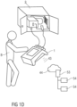
- FIG 10 a possible embodiment of the intelligent service device 1 and a portable computer device 21 as information carrier 15 in the center of a communication arrangement are shown.
- the service device 1 is in radio communication with the portable computer device 15, 21.
- the portable computer device 15, 21 is connected to a server 44 via an internet-based connection 43.
- the air conditioning system 2 is provided with a machine-readable marking 48.
- the information carrier 15 is designed such that it can identify the air conditioning system 2 using the machine-readable marking 48.
- the air conditioning system 2 has a schematically indicated air conditioning control and/or communication unit 49.
- the information carrier 15 can be in radio communication with this air conditioning control and/or communication unit 49.
- a satellite-based positioning system 50 is shown schematically. Both the air conditioning control and/or communication unit 49 and the information carrier 15 can be connected to this satellite-based positioning system 50 and thus determine their positions.
- Additional computing devices 47 can be connected to the server 44 via internet-based connections 43.
- the server 44 provides information, such as system data and measurement logs 51, which can be retrieved and displayed by the computing devices 47.
Landscapes
- Engineering & Computer Science (AREA)
- General Physics & Mathematics (AREA)
- Physics & Mathematics (AREA)
- Computer Networks & Wireless Communication (AREA)
- Signal Processing (AREA)
- Chemical & Material Sciences (AREA)
- Combustion & Propulsion (AREA)
- Mechanical Engineering (AREA)
- General Engineering & Computer Science (AREA)
- Medical Informatics (AREA)
- General Health & Medical Sciences (AREA)
- Computing Systems (AREA)
- Health & Medical Sciences (AREA)
- Arrangements For Transmission Of Measured Signals (AREA)
- Air Conditioning Control Device (AREA)
Applications Claiming Priority (3)
| Application Number | Priority Date | Filing Date | Title |
|---|---|---|---|
| DE102018008125 | 2018-10-15 | ||
| PCT/EP2019/077983 WO2020079005A1 (de) | 2018-10-15 | 2019-10-15 | Intelligentes messgerät |
| EP19789943.8A EP3841357B1 (de) | 2018-10-15 | 2019-10-15 | Intelligentes messgerät |
Related Parent Applications (2)
| Application Number | Title | Priority Date | Filing Date |
|---|---|---|---|
| EP19789943.8A Division-Into EP3841357B1 (de) | 2018-10-15 | 2019-10-15 | Intelligentes messgerät |
| EP19789943.8A Division EP3841357B1 (de) | 2018-10-15 | 2019-10-15 | Intelligentes messgerät |
Publications (2)
| Publication Number | Publication Date |
|---|---|
| EP4130686A1 EP4130686A1 (de) | 2023-02-08 |
| EP4130686B1 true EP4130686B1 (de) | 2025-03-12 |
Family
ID=68289974
Family Applications (2)
| Application Number | Title | Priority Date | Filing Date |
|---|---|---|---|
| EP22197481.9A Active EP4130686B1 (de) | 2018-10-15 | 2019-10-15 | Verfahren zur durchführung von messaufgaben und zur verwaltung von messdaten |
| EP19789943.8A Active EP3841357B1 (de) | 2018-10-15 | 2019-10-15 | Intelligentes messgerät |
Family Applications After (1)
| Application Number | Title | Priority Date | Filing Date |
|---|---|---|---|
| EP19789943.8A Active EP3841357B1 (de) | 2018-10-15 | 2019-10-15 | Intelligentes messgerät |
Country Status (5)
| Country | Link |
|---|---|
| US (1) | US12111065B2 (pl) |
| EP (2) | EP4130686B1 (pl) |
| CN (1) | CN112673237A (pl) |
| PL (1) | PL4130686T3 (pl) |
| WO (1) | WO2020079005A1 (pl) |
Families Citing this family (6)
| Publication number | Priority date | Publication date | Assignee | Title |
|---|---|---|---|---|
| US11953221B2 (en) * | 2020-02-07 | 2024-04-09 | Venstar, Llc | Easy control to sensor select for HVAC systems |
| CN113532846B (zh) * | 2021-09-14 | 2021-11-30 | 南通沃特力机械制造有限公司 | 一种组装后的泵体阀门的自动质检系统及方法 |
| US20230332813A1 (en) * | 2022-04-14 | 2023-10-19 | Testo SE & Co. KGaA | Automatic refrigerant filling |
| EP4336365A1 (en) * | 2022-09-12 | 2024-03-13 | Canon Production Printing Holding B.V. | Data processing system and a method for providing status information of the data processing system |
| DE102023130701A1 (de) * | 2023-11-07 | 2025-05-08 | Dräger Safety AG & Co. KGaA | Verfahren und Vorrichtung zum Betreiben einer Sensor-Anordnung |
| US20250389556A1 (en) * | 2024-06-25 | 2025-12-25 | Rosemount Inc. | Sensor devices with option modules |
Family Cites Families (44)
| Publication number | Priority date | Publication date | Assignee | Title |
|---|---|---|---|---|
| DE3642141A1 (de) * | 1986-12-10 | 1988-06-16 | Philips Patentverwaltung | Verfahren zur dezentralen netzersatzschaltung |
| JPH08213965A (ja) | 1995-02-02 | 1996-08-20 | Fujitsu Ltd | Sdhネットワークにおける無線回線の救済方法及び無線装置 |
| DE19800854C1 (de) * | 1998-01-13 | 1999-06-02 | Bkm Kaeltemechanik Bobbau Gmbh | Verfahren und Kontrollarmatur zum Messen, Kontrollieren und Auswerten physikalischer Parameter von im Kreislauf geführten gasförmigen und/oder flüssiggasförmigen Druckmedien und/oder Kältemitteln |
| US20060041335A9 (en) * | 2001-05-11 | 2006-02-23 | Rossi Todd M | Apparatus and method for servicing vapor compression cycle equipment |
| US20030114206A1 (en) * | 2001-08-24 | 2003-06-19 | United Parcel Service Of America, Inc. | Portable data acquisition and management system and associated device and method |
| JP2004096906A (ja) * | 2002-08-30 | 2004-03-25 | E-Plat Co Ltd | 電力管理システム、電力管理方法、キュービクル装置、計測装置、通信装置、分電盤、電力管理用サーバ |
| JP4396286B2 (ja) * | 2004-01-21 | 2010-01-13 | 三菱電機株式会社 | 機器診断装置および機器監視システム |
| US7424343B2 (en) * | 2004-08-11 | 2008-09-09 | Lawrence Kates | Method and apparatus for load reduction in an electric power system |
| JP5110805B2 (ja) * | 2005-11-18 | 2012-12-26 | キヤノン株式会社 | 有線及び無線通信可能な通信端末、通信方法、プログラム |
| WO2007125020A1 (de) * | 2006-04-26 | 2007-11-08 | Endress+Hauser Conducta Gesellschaft Für Mess- Und Regeltechnik Mbh+Co. Kg | Sensor für eine messstelle und verfahren zur überprüfung eines sensors für eine messstelle |
| CN201041441Y (zh) * | 2006-06-10 | 2008-03-26 | 深圳市元征科技股份有限公司 | 应用于冷媒加注设备的制冷剂测量补充系统 |
| CN100562048C (zh) * | 2006-06-16 | 2009-11-18 | 电子科技大学 | 一种无线有线融合式传感器网络系统 |
| US10845399B2 (en) * | 2007-04-03 | 2020-11-24 | Electro Industries/Gaugetech | System and method for performing data transfers in an intelligent electronic device |
| US20090113901A1 (en) * | 2007-11-07 | 2009-05-07 | Interdynamics Inc. | Method and Apparatus for Servicing a Coolant System |
| DE202008000837U1 (de) * | 2008-01-21 | 2008-06-12 | Sun-Wonder Industrial Co., Ltd., Kueishan Hsiang | Digitaler Kühlmitteldruckmesser |
| US8322151B1 (en) * | 2008-08-13 | 2012-12-04 | Demand Side Environmental, LLC | Systems and methods for gathering data from and diagnosing the status of an air conditioner |
| US20120105249A1 (en) | 2008-09-09 | 2012-05-03 | T-Systems International Gmbh | Method and Distributed System for Detecting and Managing Data from a Plurality of Measuring Devices |
| DE102009026430A1 (de) | 2009-05-25 | 2010-12-09 | Robert Bosch Gmbh | Fahrzeugsensor, System mit einem Steuergerät zur Fahrzeugzustandsbestimmung und wenigstens zwei Fahrzeugsensoren und Verfahren zum Betreiben eines Systems mit einem Steuergerät zur Fahrzeugzustandsbestimmung und wenigstens zwei Fahrzeugsensoren |
| IT1396083B1 (it) * | 2009-09-30 | 2012-11-09 | Texa Spa | Stazione multi-serbatoio per ricaricare un fluido refrigerante in un impianto di climatizzazione di un autoveicolo e metodo per determinare il peso del fuido refrigerante contenuto in ciascuno dei serbatoi |
| JP5175914B2 (ja) * | 2010-10-26 | 2013-04-03 | 富士フイルム株式会社 | 無線超音波診断システム |
| CN201902824U (zh) * | 2010-12-15 | 2011-07-20 | 浙江欧伦泰防火设备有限公司 | 一种液态co2灭火器充装设备 |
| CN102401518A (zh) * | 2011-12-06 | 2012-04-04 | 合肥美的荣事达电冰箱有限公司 | 一种制冷剂充注系统 |
| CN202421061U (zh) * | 2012-01-19 | 2012-09-05 | 公安部天津消防研究所 | 一种用于七氟丙烷热分解产生hf的浓度实时测量装置 |
| CN102697498A (zh) * | 2012-04-28 | 2012-10-03 | 孙剑 | 基于人体成分测量仪器的远程数据采集系统及方法 |
| CN102692912B (zh) * | 2012-06-11 | 2015-06-17 | 成都瑞特数字科技有限责任公司 | 一种基于有线和无线热备冗余通信的现场级低成本冗余测控网络 |
| DE102012019616A1 (de) * | 2012-10-01 | 2014-04-03 | Wika Alexander Wiegand Se & Co. Kg | Auswerteeinheit für eine physikalische Größe |
| US9710414B2 (en) * | 2012-10-27 | 2017-07-18 | Ping Liang | Interchangeable wireless sensing apparatus for mobile or networked devices |
| DE102012021533A1 (de) * | 2012-10-31 | 2014-04-30 | Festo Ag & Co. Kg | Druckluft-Wartungsgerät und damit ausgestattete Verbrauchersteuervorrichtung |
| CN105209838B (zh) * | 2013-03-12 | 2018-06-08 | 博世汽车服务解决方案公司 | 提高具有止回阀装置和温控式维护软管的制冷剂回收单元的灌充精确性的方法以及设备 |
| WO2014149174A1 (en) * | 2013-03-15 | 2014-09-25 | Stride Tool, Inc. | Smart hvac manifold system |
| CN203174204U (zh) * | 2013-03-29 | 2013-09-04 | 四川众力氟业有限责任公司 | 一种电槽自动控制加酸装置 |
| CN104296945A (zh) * | 2013-07-15 | 2015-01-21 | 珠海格力电器股份有限公司 | 蒸发器检漏系统及检漏方法 |
| DE102013113258A1 (de) | 2013-11-29 | 2015-06-03 | Endress + Hauser Conducta Gesellschaft für Mess- und Regeltechnik mbH + Co. KG | Sensor und Messanordnung |
| CN204085725U (zh) * | 2014-07-17 | 2015-01-07 | 台州朗讯机械有限公司 | 一种多功能冷媒测量数显表装置 |
| CN104258638A (zh) * | 2014-09-30 | 2015-01-07 | 东莞市高朗实业有限公司 | 一种电动送风空气过滤器、电焊变光护目镜及其控制器 |
| CN104596708A (zh) * | 2014-12-23 | 2015-05-06 | 珠海格力电器股份有限公司 | 空调检漏的方法和装置 |
| CN204612789U (zh) * | 2015-01-20 | 2015-09-02 | 金华市威科工贸有限公司 | 一种无线大流量可编程冷媒加注秤 |
| WO2017022905A1 (ko) * | 2015-07-31 | 2017-02-09 | (주)멀린 | 환경 감시 시스템 및 방법 |
| CN205211145U (zh) * | 2015-12-01 | 2016-05-04 | 国家电网公司 | 智能装置远程数据采集系统 |
| US10033706B2 (en) * | 2015-12-04 | 2018-07-24 | Samsara Networks Inc. | Secure offline data offload in a sensor network |
| CN106568250A (zh) * | 2016-10-28 | 2017-04-19 | 浙江飞越机电有限公司 | 冷媒加注机及用该设备进行抽真空、检漏和冷媒加注的方法 |
| CN106840549B (zh) * | 2016-12-29 | 2019-11-19 | 华为数字技术(苏州)有限公司 | 一种空调检测装置 |
| CN206439619U (zh) * | 2017-01-13 | 2017-08-25 | 南京华特硅材料有限公司 | 一种电子级氧化亚氮气瓶充装及管道内余气的处理系统 |
| CN107677432A (zh) * | 2017-10-24 | 2018-02-09 | 湖北鑫星冷机制造有限公司 | 一种汽车空调压缩机阀组气密性检测装置 |
-
2019
- 2019-10-15 CN CN201980058199.4A patent/CN112673237A/zh active Pending
- 2019-10-15 EP EP22197481.9A patent/EP4130686B1/de active Active
- 2019-10-15 EP EP19789943.8A patent/EP3841357B1/de active Active
- 2019-10-15 PL PL22197481.9T patent/PL4130686T3/pl unknown
- 2019-10-15 WO PCT/EP2019/077983 patent/WO2020079005A1/de not_active Ceased
-
2021
- 2021-04-15 US US17/231,654 patent/US12111065B2/en active Active
Also Published As
| Publication number | Publication date |
|---|---|
| EP3841357B1 (de) | 2022-11-23 |
| WO2020079005A1 (de) | 2020-04-23 |
| EP4130686A1 (de) | 2023-02-08 |
| CN112673237A (zh) | 2021-04-16 |
| EP3841357A1 (de) | 2021-06-30 |
| US12111065B2 (en) | 2024-10-08 |
| US20210231335A1 (en) | 2021-07-29 |
| PL4130686T3 (pl) | 2025-07-21 |
Similar Documents
| Publication | Publication Date | Title |
|---|---|---|
| EP4130686B1 (de) | Verfahren zur durchführung von messaufgaben und zur verwaltung von messdaten | |
| EP2962163B1 (de) | Steuervorrichtung, komponenten und mobile servicevorrichtung für eine hvac-anlage | |
| US11096029B2 (en) | Mobile communication device and method for managing operation of a plurality of actuators | |
| EP3069488B1 (en) | Communicator with profiles | |
| JP5636106B2 (ja) | 改善された診断性を有する手持ち型フィールドメンテナンスツール | |
| CN104375473A (zh) | 维修现场设备的方法 | |
| US12222694B2 (en) | Cloud-hosted interface for portable device communicators | |
| CN104281678A (zh) | 一种小卫星智能状态监视系统 | |
| CN107610267A (zh) | 站点巡检方法 | |
| DE112016003869T5 (de) | System und Verfahren zur Inbetriebnahme und zur Wartung von Industrieeinrichtungen | |
| CN106468912A (zh) | 诊断方法、id模块及过程控制系统 | |
| US20150204752A1 (en) | Method for detecting at least one variable associated with the formation of at least one joint and/or a machine during assembly of a pipeline system | |
| TWI693490B (zh) | 工業物聯網系統及其資料處理裝置 | |
| US11520793B2 (en) | Servicing, diagnosing, logging, and surveying building equipment assets | |
| CN109671176B (zh) | 烟草设备巡检系统实时数据采集系统及方法 | |
| KR20110129656A (ko) | 자동 교정 장치, 자동 교정 방법 및 자동 교정 방법을 기록한 프로그램 기록 매체 | |
| US9817780B2 (en) | Communicator with profiles | |
| CN114117831A (zh) | 智慧实验室的计量器具量值数据分析方法及装置 | |
| CN111912078A (zh) | Hvac系统的数据映射方法、系统、控制方法和存储介质 | |
| AT524951B1 (de) | Prüfling mit Messmodul | |
| EP4431823A1 (de) | Verfahren zur inbetriebnahme einer pumpenbaugruppe, computerprogramm, regel- und steuergerät und heizgerät | |
| US20150198344A1 (en) | Hoseless Wireless Gauges for HVAC Maintenance and Repair | |
| DE29800404U1 (de) | Kontrollarmatur zum Messen, Kontrollieren und Auswerten physikalischer Parameter von im Kreislauf geführten gasförmigen und/oder flüssiggasförmigen Druckmedien | |
| CN103607336A (zh) | 一种用于家居设备在自动化系统中自动集成的方法 |
Legal Events
| Date | Code | Title | Description |
|---|---|---|---|
| PUAI | Public reference made under article 153(3) epc to a published international application that has entered the european phase |
Free format text: ORIGINAL CODE: 0009012 |
|
| STAA | Information on the status of an ep patent application or granted ep patent |
Free format text: STATUS: THE APPLICATION HAS BEEN PUBLISHED |
|
| AC | Divisional application: reference to earlier application |
Ref document number: 3841357 Country of ref document: EP Kind code of ref document: P |
|
| AK | Designated contracting states |
Kind code of ref document: A1 Designated state(s): AL AT BE BG CH CY CZ DE DK EE ES FI FR GB GR HR HU IE IS IT LI LT LU LV MC MK MT NL NO PL PT RO RS SE SI SK SM TR |
|
| STAA | Information on the status of an ep patent application or granted ep patent |
Free format text: STATUS: REQUEST FOR EXAMINATION WAS MADE |
|
| 17P | Request for examination filed |
Effective date: 20230728 |
|
| RBV | Designated contracting states (corrected) |
Designated state(s): AL AT BE BG CH CY CZ DE DK EE ES FI FR GB GR HR HU IE IS IT LI LT LU LV MC MK MT NL NO PL PT RO RS SE SI SK SM TR |
|
| GRAP | Despatch of communication of intention to grant a patent |
Free format text: ORIGINAL CODE: EPIDOSNIGR1 |
|
| STAA | Information on the status of an ep patent application or granted ep patent |
Free format text: STATUS: GRANT OF PATENT IS INTENDED |
|
| RIC1 | Information provided on ipc code assigned before grant |
Ipc: G01D 21/00 20060101AFI20240930BHEP |
|
| INTG | Intention to grant announced |
Effective date: 20241018 |
|
| GRAS | Grant fee paid |
Free format text: ORIGINAL CODE: EPIDOSNIGR3 |
|
| GRAA | (expected) grant |
Free format text: ORIGINAL CODE: 0009210 |
|
| STAA | Information on the status of an ep patent application or granted ep patent |
Free format text: STATUS: THE PATENT HAS BEEN GRANTED |
|
| AC | Divisional application: reference to earlier application |
Ref document number: 3841357 Country of ref document: EP Kind code of ref document: P |
|
| AK | Designated contracting states |
Kind code of ref document: B1 Designated state(s): AL AT BE BG CH CY CZ DE DK EE ES FI FR GB GR HR HU IE IS IT LI LT LU LV MC MK MT NL NO PL PT RO RS SE SI SK SM TR |
|
| P01 | Opt-out of the competence of the unified patent court (upc) registered |
Free format text: CASE NUMBER: APP_4987/2025 Effective date: 20250130 |
|
| REG | Reference to a national code |
Ref country code: GB Ref legal event code: FG4D Free format text: NOT ENGLISH |
|
| REG | Reference to a national code |
Ref country code: CH Ref legal event code: EP |
|
| REG | Reference to a national code |
Ref country code: DE Ref legal event code: R096 Ref document number: 502019013065 Country of ref document: DE |
|
| REG | Reference to a national code |
Ref country code: IE Ref legal event code: FG4D Free format text: LANGUAGE OF EP DOCUMENT: GERMAN |
|
| REG | Reference to a national code |
Ref country code: NL Ref legal event code: FP |
|
| PG25 | Lapsed in a contracting state [announced via postgrant information from national office to epo] |
Ref country code: RS Free format text: LAPSE BECAUSE OF FAILURE TO SUBMIT A TRANSLATION OF THE DESCRIPTION OR TO PAY THE FEE WITHIN THE PRESCRIBED TIME-LIMIT Effective date: 20250612 |
|
| PG25 | Lapsed in a contracting state [announced via postgrant information from national office to epo] |
Ref country code: FI Free format text: LAPSE BECAUSE OF FAILURE TO SUBMIT A TRANSLATION OF THE DESCRIPTION OR TO PAY THE FEE WITHIN THE PRESCRIBED TIME-LIMIT Effective date: 20250312 |
|
| PG25 | Lapsed in a contracting state [announced via postgrant information from national office to epo] |
Ref country code: ES Free format text: LAPSE BECAUSE OF FAILURE TO SUBMIT A TRANSLATION OF THE DESCRIPTION OR TO PAY THE FEE WITHIN THE PRESCRIBED TIME-LIMIT Effective date: 20250312 |
|
| REG | Reference to a national code |
Ref country code: LT Ref legal event code: MG9D |
|
| PG25 | Lapsed in a contracting state [announced via postgrant information from national office to epo] |
Ref country code: NO Free format text: LAPSE BECAUSE OF FAILURE TO SUBMIT A TRANSLATION OF THE DESCRIPTION OR TO PAY THE FEE WITHIN THE PRESCRIBED TIME-LIMIT Effective date: 20250612 |
|
| PG25 | Lapsed in a contracting state [announced via postgrant information from national office to epo] |
Ref country code: HR Free format text: LAPSE BECAUSE OF FAILURE TO SUBMIT A TRANSLATION OF THE DESCRIPTION OR TO PAY THE FEE WITHIN THE PRESCRIBED TIME-LIMIT Effective date: 20250312 |
|
| PG25 | Lapsed in a contracting state [announced via postgrant information from national office to epo] |
Ref country code: LV Free format text: LAPSE BECAUSE OF FAILURE TO SUBMIT A TRANSLATION OF THE DESCRIPTION OR TO PAY THE FEE WITHIN THE PRESCRIBED TIME-LIMIT Effective date: 20250312 |
|
| PG25 | Lapsed in a contracting state [announced via postgrant information from national office to epo] |
Ref country code: GR Free format text: LAPSE BECAUSE OF FAILURE TO SUBMIT A TRANSLATION OF THE DESCRIPTION OR TO PAY THE FEE WITHIN THE PRESCRIBED TIME-LIMIT Effective date: 20250613 Ref country code: BG Free format text: LAPSE BECAUSE OF FAILURE TO SUBMIT A TRANSLATION OF THE DESCRIPTION OR TO PAY THE FEE WITHIN THE PRESCRIBED TIME-LIMIT Effective date: 20250312 |
|
| PG25 | Lapsed in a contracting state [announced via postgrant information from national office to epo] |
Ref country code: SE Free format text: LAPSE BECAUSE OF FAILURE TO SUBMIT A TRANSLATION OF THE DESCRIPTION OR TO PAY THE FEE WITHIN THE PRESCRIBED TIME-LIMIT Effective date: 20250312 |
|
| PG25 | Lapsed in a contracting state [announced via postgrant information from national office to epo] |
Ref country code: SM Free format text: LAPSE BECAUSE OF FAILURE TO SUBMIT A TRANSLATION OF THE DESCRIPTION OR TO PAY THE FEE WITHIN THE PRESCRIBED TIME-LIMIT Effective date: 20250312 |
|
| PG25 | Lapsed in a contracting state [announced via postgrant information from national office to epo] |
Ref country code: PT Free format text: LAPSE BECAUSE OF FAILURE TO SUBMIT A TRANSLATION OF THE DESCRIPTION OR TO PAY THE FEE WITHIN THE PRESCRIBED TIME-LIMIT Effective date: 20250714 |
|
| PG25 | Lapsed in a contracting state [announced via postgrant information from national office to epo] |
Ref country code: IT Free format text: LAPSE BECAUSE OF FAILURE TO SUBMIT A TRANSLATION OF THE DESCRIPTION OR TO PAY THE FEE WITHIN THE PRESCRIBED TIME-LIMIT Effective date: 20250312 |
|
| PG25 | Lapsed in a contracting state [announced via postgrant information from national office to epo] |
Ref country code: CZ Free format text: LAPSE BECAUSE OF FAILURE TO SUBMIT A TRANSLATION OF THE DESCRIPTION OR TO PAY THE FEE WITHIN THE PRESCRIBED TIME-LIMIT Effective date: 20250312 Ref country code: EE Free format text: LAPSE BECAUSE OF FAILURE TO SUBMIT A TRANSLATION OF THE DESCRIPTION OR TO PAY THE FEE WITHIN THE PRESCRIBED TIME-LIMIT Effective date: 20250312 |
|
| PG25 | Lapsed in a contracting state [announced via postgrant information from national office to epo] |
Ref country code: RO Free format text: LAPSE BECAUSE OF FAILURE TO SUBMIT A TRANSLATION OF THE DESCRIPTION OR TO PAY THE FEE WITHIN THE PRESCRIBED TIME-LIMIT Effective date: 20250312 |
|
| PG25 | Lapsed in a contracting state [announced via postgrant information from national office to epo] |
Ref country code: SK Free format text: LAPSE BECAUSE OF FAILURE TO SUBMIT A TRANSLATION OF THE DESCRIPTION OR TO PAY THE FEE WITHIN THE PRESCRIBED TIME-LIMIT Effective date: 20250312 |
|
| PG25 | Lapsed in a contracting state [announced via postgrant information from national office to epo] |
Ref country code: IS Free format text: LAPSE BECAUSE OF FAILURE TO SUBMIT A TRANSLATION OF THE DESCRIPTION OR TO PAY THE FEE WITHIN THE PRESCRIBED TIME-LIMIT Effective date: 20250712 |
|
| PGFP | Annual fee paid to national office [announced via postgrant information from national office to epo] |
Ref country code: NL Payment date: 20251030 Year of fee payment: 7 |
|
| REG | Reference to a national code |
Ref country code: DE Ref legal event code: R097 Ref document number: 502019013065 Country of ref document: DE |
|
| PGFP | Annual fee paid to national office [announced via postgrant information from national office to epo] |
Ref country code: DE Payment date: 20251118 Year of fee payment: 7 |
|
| PG25 | Lapsed in a contracting state [announced via postgrant information from national office to epo] |
Ref country code: DK Free format text: LAPSE BECAUSE OF FAILURE TO SUBMIT A TRANSLATION OF THE DESCRIPTION OR TO PAY THE FEE WITHIN THE PRESCRIBED TIME-LIMIT Effective date: 20250312 |
|
| PGFP | Annual fee paid to national office [announced via postgrant information from national office to epo] |
Ref country code: FR Payment date: 20251030 Year of fee payment: 7 |
|
| PLBE | No opposition filed within time limit |
Free format text: ORIGINAL CODE: 0009261 |
|
| STAA | Information on the status of an ep patent application or granted ep patent |
Free format text: STATUS: NO OPPOSITION FILED WITHIN TIME LIMIT |
|
| REG | Reference to a national code |
Ref country code: CH Ref legal event code: L10 Free format text: ST27 STATUS EVENT CODE: U-0-0-L10-L00 (AS PROVIDED BY THE NATIONAL OFFICE) Effective date: 20260121 |
|
| PGFP | Annual fee paid to national office [announced via postgrant information from national office to epo] |
Ref country code: PL Payment date: 20251104 Year of fee payment: 7 |