EP4130569B1 - Vehicle lighting - Google Patents
Vehicle lighting Download PDFInfo
- Publication number
- EP4130569B1 EP4130569B1 EP21776071.9A EP21776071A EP4130569B1 EP 4130569 B1 EP4130569 B1 EP 4130569B1 EP 21776071 A EP21776071 A EP 21776071A EP 4130569 B1 EP4130569 B1 EP 4130569B1
- Authority
- EP
- European Patent Office
- Prior art keywords
- light
- lens body
- light source
- incidence
- section
- Prior art date
- Legal status (The legal status is an assumption and is not a legal conclusion. Google has not performed a legal analysis and makes no representation as to the accuracy of the status listed.)
- Active
Links
Images

Classifications
-
- F—MECHANICAL ENGINEERING; LIGHTING; HEATING; WEAPONS; BLASTING
- F21—LIGHTING
- F21S—NON-PORTABLE LIGHTING DEVICES; SYSTEMS THEREOF; VEHICLE LIGHTING DEVICES SPECIALLY ADAPTED FOR VEHICLE EXTERIORS
- F21S41/00—Illuminating devices specially adapted for vehicle exteriors, e.g. headlamps
- F21S41/10—Illuminating devices specially adapted for vehicle exteriors, e.g. headlamps characterised by the light source
- F21S41/14—Illuminating devices specially adapted for vehicle exteriors, e.g. headlamps characterised by the light source characterised by the type of light source
- F21S41/141—Light emitting diodes [LED]
- F21S41/143—Light emitting diodes [LED] the main emission direction of the LED being parallel to the optical axis of the illuminating device
-
- F—MECHANICAL ENGINEERING; LIGHTING; HEATING; WEAPONS; BLASTING
- F21—LIGHTING
- F21S—NON-PORTABLE LIGHTING DEVICES; SYSTEMS THEREOF; VEHICLE LIGHTING DEVICES SPECIALLY ADAPTED FOR VEHICLE EXTERIORS
- F21S41/00—Illuminating devices specially adapted for vehicle exteriors, e.g. headlamps
- F21S41/10—Illuminating devices specially adapted for vehicle exteriors, e.g. headlamps characterised by the light source
- F21S41/19—Attachment of light sources or lamp holders
-
- F—MECHANICAL ENGINEERING; LIGHTING; HEATING; WEAPONS; BLASTING
- F21—LIGHTING
- F21S—NON-PORTABLE LIGHTING DEVICES; SYSTEMS THEREOF; VEHICLE LIGHTING DEVICES SPECIALLY ADAPTED FOR VEHICLE EXTERIORS
- F21S41/00—Illuminating devices specially adapted for vehicle exteriors, e.g. headlamps
- F21S41/20—Illuminating devices specially adapted for vehicle exteriors, e.g. headlamps characterised by refractors, transparent cover plates, light guides or filters
- F21S41/24—Light guides
-
- F—MECHANICAL ENGINEERING; LIGHTING; HEATING; WEAPONS; BLASTING
- F21—LIGHTING
- F21S—NON-PORTABLE LIGHTING DEVICES; SYSTEMS THEREOF; VEHICLE LIGHTING DEVICES SPECIALLY ADAPTED FOR VEHICLE EXTERIORS
- F21S41/00—Illuminating devices specially adapted for vehicle exteriors, e.g. headlamps
- F21S41/20—Illuminating devices specially adapted for vehicle exteriors, e.g. headlamps characterised by refractors, transparent cover plates, light guides or filters
- F21S41/25—Projection lenses
- F21S41/265—Composite lenses; Lenses with a patch-like shape
-
- F—MECHANICAL ENGINEERING; LIGHTING; HEATING; WEAPONS; BLASTING
- F21—LIGHTING
- F21S—NON-PORTABLE LIGHTING DEVICES; SYSTEMS THEREOF; VEHICLE LIGHTING DEVICES SPECIALLY ADAPTED FOR VEHICLE EXTERIORS
- F21S41/00—Illuminating devices specially adapted for vehicle exteriors, e.g. headlamps
- F21S41/20—Illuminating devices specially adapted for vehicle exteriors, e.g. headlamps characterised by refractors, transparent cover plates, light guides or filters
- F21S41/25—Projection lenses
- F21S41/27—Thick lenses
-
- F—MECHANICAL ENGINEERING; LIGHTING; HEATING; WEAPONS; BLASTING
- F21—LIGHTING
- F21S—NON-PORTABLE LIGHTING DEVICES; SYSTEMS THEREOF; VEHICLE LIGHTING DEVICES SPECIALLY ADAPTED FOR VEHICLE EXTERIORS
- F21S41/00—Illuminating devices specially adapted for vehicle exteriors, e.g. headlamps
- F21S41/20—Illuminating devices specially adapted for vehicle exteriors, e.g. headlamps characterised by refractors, transparent cover plates, light guides or filters
- F21S41/285—Refractors, transparent cover plates, light guides or filters not provided in groups F21S41/24 - F21S41/2805
-
- F—MECHANICAL ENGINEERING; LIGHTING; HEATING; WEAPONS; BLASTING
- F21—LIGHTING
- F21S—NON-PORTABLE LIGHTING DEVICES; SYSTEMS THEREOF; VEHICLE LIGHTING DEVICES SPECIALLY ADAPTED FOR VEHICLE EXTERIORS
- F21S41/00—Illuminating devices specially adapted for vehicle exteriors, e.g. headlamps
- F21S41/20—Illuminating devices specially adapted for vehicle exteriors, e.g. headlamps characterised by refractors, transparent cover plates, light guides or filters
- F21S41/29—Attachment thereof
- F21S41/295—Attachment thereof specially adapted to projection lenses
-
- F—MECHANICAL ENGINEERING; LIGHTING; HEATING; WEAPONS; BLASTING
- F21—LIGHTING
- F21S—NON-PORTABLE LIGHTING DEVICES; SYSTEMS THEREOF; VEHICLE LIGHTING DEVICES SPECIALLY ADAPTED FOR VEHICLE EXTERIORS
- F21S41/00—Illuminating devices specially adapted for vehicle exteriors, e.g. headlamps
- F21S41/30—Illuminating devices specially adapted for vehicle exteriors, e.g. headlamps characterised by reflectors
- F21S41/32—Optical layout thereof
- F21S41/322—Optical layout thereof the reflector using total internal reflection
-
- F—MECHANICAL ENGINEERING; LIGHTING; HEATING; WEAPONS; BLASTING
- F21—LIGHTING
- F21S—NON-PORTABLE LIGHTING DEVICES; SYSTEMS THEREOF; VEHICLE LIGHTING DEVICES SPECIALLY ADAPTED FOR VEHICLE EXTERIORS
- F21S41/00—Illuminating devices specially adapted for vehicle exteriors, e.g. headlamps
- F21S41/60—Illuminating devices specially adapted for vehicle exteriors, e.g. headlamps characterised by a variable light distribution
- F21S41/65—Illuminating devices specially adapted for vehicle exteriors, e.g. headlamps characterised by a variable light distribution by acting on light sources
- F21S41/663—Illuminating devices specially adapted for vehicle exteriors, e.g. headlamps characterised by a variable light distribution by acting on light sources by switching light sources
-
- F—MECHANICAL ENGINEERING; LIGHTING; HEATING; WEAPONS; BLASTING
- F21—LIGHTING
- F21S—NON-PORTABLE LIGHTING DEVICES; SYSTEMS THEREOF; VEHICLE LIGHTING DEVICES SPECIALLY ADAPTED FOR VEHICLE EXTERIORS
- F21S45/00—Arrangements within vehicle lighting devices specially adapted for vehicle exteriors, for purposes other than emission or distribution of light
- F21S45/40—Cooling of lighting devices
- F21S45/47—Passive cooling, e.g. using fins, thermal conductive elements or openings
-
- F—MECHANICAL ENGINEERING; LIGHTING; HEATING; WEAPONS; BLASTING
- F21—LIGHTING
- F21W—INDEXING SCHEME ASSOCIATED WITH SUBCLASSES F21K, F21L, F21S and F21V, RELATING TO USES OR APPLICATIONS OF LIGHTING DEVICES OR SYSTEMS
- F21W2102/00—Exterior vehicle lighting devices for illuminating purposes
- F21W2102/10—Arrangement or contour of the emitted light
- F21W2102/13—Arrangement or contour of the emitted light for high-beam region or low-beam region
- F21W2102/135—Arrangement or contour of the emitted light for high-beam region or low-beam region the light having cut-off lines, i.e. clear borderlines between emitted regions and dark regions
-
- F—MECHANICAL ENGINEERING; LIGHTING; HEATING; WEAPONS; BLASTING
- F21—LIGHTING
- F21Y—INDEXING SCHEME ASSOCIATED WITH SUBCLASSES F21K, F21L, F21S and F21V, RELATING TO THE FORM OR THE KIND OF THE LIGHT SOURCES OR OF THE COLOUR OF THE LIGHT EMITTED
- F21Y2115/00—Light-generating elements of semiconductor light sources
- F21Y2115/10—Light-emitting diodes [LED]
Definitions
- the present invention relates to vehicle lighting.
- vehicle lighting such as a headlight (headlamp) for a vehicle or the like includes a light source, a reflector configured to reflect light emitted from the light source in a direction in which the vehicle advances, a shade configured to shield (cut) some of the light reflected by the reflector, and a projection lens configured to project the light, some of which is cut by the shade, in the direction in which the vehicle advances.
- a headlight headlamp
- a projection lens configured to project the light, some of which is cut by the shade, in the direction in which the vehicle advances.
- a light distribution pattern for a low beam including a cutoff line on an upper end is formed by inverting and projecting a light source image defined by a front end of the shade using the projection lens as a passing beam (low beam).
- a light distribution pattern for a high beam is formed above the light distribution pattern for a low beam by disposing a separate light source configured to emit light in the direction in which the vehicle advances below the shade, and projecting light emitted from the light source using the projection lens as a traveling beam (high beam).
- EP 3 604 910 A1 discloses an optical part which includes a transparent or translucent block having first and second collimators that are intended to receive the beams of first and second light sources so that the beams enter into the block.
- the collimators are arranged in such a way that these sources may be positioned in a plane that an intermediate exit dioptric interface toward which the first collimator guides the first beam so that this first beam exits from the block through this intermediate dioptric interface.
- a cutoff dioptric interface forms a folder for the first beam and for the second beam, and the first collimator with the intermediate dioptric interface and the second collimator being arranged so that each beam converges on the cutoff edge of the folder.
- EP 3 173 687 A1 discloses a lens body including a first lens unit configured to form a first light distribution pattern which includes a first cut-off line, and a second lens unit configured to form a second light distribution pattern which includes a second cut-off line, wherein the first lens unit forms the first light distribution pattern when light from a first light source which entered the first lens unit is emitted from the first lens unit, the second lens unit forms the second light distribution pattern when light from a second light source which entered the second lens unit is emitted from the second lens unit, and the first lens unit and the second lens unit are integrally molded.
- An aspect of the present invention provides vehicle lighting capable of obtaining a good light distribution pattern.
- the lighting body is constituted by a housing, a front surface of which is open, and a transparent lens cover configured to cover an opening of the housing.
- a shape of the lighting body may be appropriately changed according to a design or the like of the vehicle.
- the first light source 2 and the second light source 3 are constituted by, for example, light emitting diodes (LEDs) configured to emit white light.
- LEDs light emitting diodes
- a high output (high brightness) type LED for vehicle illumination for example, an SMD LED or the like
- a light emitting element such as a laser diode (LD) or the like can be used, in addition to the above-mentioned LED.
- the vehicle lighting 1A of the embodiment in a state in which the first light source 2 and the second light source 3 are adjacent to each other, they are arranged next to each other in a vertical direction (upward/downward direction) of the vehicle lighting 1A.
- one LED that constitutes the first light source 2 is disposed on an upper side
- one LED that constitutes the second light source 3 is disposed on a lower side.
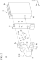
- the first light source 2 and the second light source 3 are mounted on a circuit substrate 5 on the side of one surface (in the embodiment, a front surface) on which driving circuits configured to drive the LEDs are provided. Accordingly, the first light source 2 and the second light source 3 radially emit the first light L1 and the second light L2 toward the side in front (+X axis side). That is, the first light source 2 and the second light source 3 are provided on the same surface of the same circuit substrate 5, and form a configuration that emits the first light L1 and the second light L2 radially in the same direction.
- a heat sink 6 configured to radiate heat emitted from the first light source 2 and the second light source 3 is attached to the circuit substrate 5 on the side of the other surface (in the embodiment, a back surface).
- the heat sink 6 is constituted by an extruded body formed of a metal having high thermal conductivity such as aluminum or the like.
- the heat sink 6 has a base section 6a in contact with the circuit substrate 5, and a plurality of fin sections 6b configured to increase a heat radiation property transferred from the circuit substrate 5 to the base section 6a.
- a configuration in which the LEDs that constitute the first light source 2 and the second light source 3 and the driving circuit configured to drive the LEDs are mounted on the circuit substrate 5 is provided in the embodiment, a configuration in which a mounting substrate on which LEDs are mounted and a circuit substrate on which a driving circuit configured to drive the LEDs is provided are separately disposed, the mounting substrate and the circuit substrate are electrically connected via a wiring cord referred to as a harness, and a driving circuit is protected from heat emitted from the LEDs may be provided.
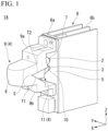
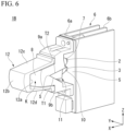
- the projection lens 4 has the first incidence section 7 located at a side facing the first light source 2, a first lens body 9 including an emission section 8 located at a side opposite to the first incidence section 7, and a second lens body 11 including the second incidence section 10 located at a side facing the second light source 3.
- a refractive index of the second lens body 11 is smaller than a refractive index of the first lens body 9.
- the first lens body 9 is formed of a polycarbonate resin (PC)
- the second lens body 11 is formed of an acryl resin (PMMA).
- the combination of materials having different refractive indices between the first lens body 9 and the second lens body 11 is not particularly limited to such a combination, and can be changed as appropriate.
- the material is not limited to the above-mentioned resin having optical transparency, and glass may also be used.
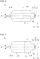
- the first lens body 9 and the second lens body 11 have a structure in which they abut each other while having first boundary surfaces T1, which are provided between the emission section 8 and the second incidence section 10, and second boundary surfaces T2, which are provided between the first incidence section 7 and the second incidence section 10 from a boundary line S with respect to the first boundary surface T1, interposed therebetween.
- the first boundary surface T1 is constituted by a surface that divides between the first lens body 9 and the second lens body 11 downward from the boundary line S, and is inclined diagonally rearward from the boundary line S.
- the second boundary surface T2 is constituted by a surface that divides between the first lens body 9 and the second lens body 11 rearward from the boundary line S, and furthermore, is inclined diagonally upward from the boundary line S.
- the boundary line S defines a cutoff line of the above-mentioned light distribution pattern for a low beam while extending in a horizontal direction (leftward/rightward direction) of the vehicle lighting 1A.
- the first lens body 9 and the second lens body 11 are closely attached or joined by abutting the first boundary surface T1 and the second boundary surface T2 with each other without interposing an air layer between the first boundary surface T1 and the second boundary surface T2.
- the first lens body 9 and the second lens body 11 formed of different resins can be integrally formed by injection molding using a mold (so-called two color formation).
- the first lens body 9 has a pair of arm sections 9a and 9b.
- the pair of arm sections 9a and 9b are provided to extend rearward from both upper and lower sides of the first lens body 9.
- tip sides of the pair of arm sections 9a and 9b have a shape folded in a direction in which they are separated from each other.
- the pair of arm sections 9a and 9b are fixed to a fixing position of a bracket or the like in the lighting body together with the circuit substrate 5 through screwing. Accordingly, in a state in which intervals between the first light source 2 and third light source 3 and between the first incidence section 7 and the second incidence section 10 are held, the first lens body 9 and the second lens body 11 are positioned and fixed to the first light source 2 and the second light source 3.
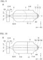
- the first incidence section 7 since the first incidence section 7 is adjacent to the second incidence section 10 while having the second boundary surface T2 sandwiched therebetween, the first incidence section 7 has a shape in which parts on the lower sides of the first condensing incidence surface 7a, the second condensing incidence surface 7b and the condensing reflection surface 7c are cut along the second boundary surface T2.
- the first light L1 entering inside of the first lens body 9 from the first condensing incidence surface 7a is condensed closer to an optical axis. Meanwhile, the first light L1 entering inside of the first lens body 9 from the second condensing incidence surface 7b is reflected at the condensing reflection surface 7c and condensed closer to the optical axis.
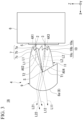
- the first light L1 entering inside of the first lens body 9 from the first incidence section 7 is guided toward a side in front of the first lens body 9 while being condensed closer toan optical axis AX2, which is inclined diagonally downward more than an optical axis AX1 of the first light L1 emitted from the first light source 2, in a vertical cross section of the vehicle lighting 1A shown in Fig. 3 .
- the first light L1 entering inside of the first lens body 9 from the first incidence section 7 is guided toward a side in front of the first lens body 9 while being parallelized with respect to the optical axis AX1 of the first light L1 in the horizontal cross section of the vehicle lighting 1A shown in Fig. 4 .
- the first incidence section 7, in the horizontal cross section of the vehicle lighting 1A a configuration in which the first light L1 enters inside of the first lens body 9 while condensed closer to the optical axis AX1 may be used.
- the first light L1 entering inside of the first lens body 9 from the first incidence section 7 is guided toward the emission section 8 in front of the first lens body 9.
- the first light L1 entering the second boundary surface T2 is reflected by the second boundary surface T2 and then guided toward the emission section 8.
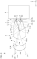
- the second incidence section 10 has a first condensing incidence surface 10a having a convex surface shape, located at a portion facing the second light source 3 and through which some of the second light L2 emitted from the second light source 3 enters, a second condensing incidence surface 10b having a substantially cylindrical shape, located at an inner circumferential side of a portion protruding toward the second light source 3 from a position surrounding the first condensing incidence surface 10a and through which some of the second light L2 emitted from the second light source 3 enters, and a condensing reflection surface 10c having a truncated conical shape, located at an outer circumferential side of the protruded portion and configured to reflect the second light L2 entering from the second condensing incidence surface 10b.
- the second light L2 entering inside of the second lens body 11 from the first condensing incidence surface 10a is condensed closer to the optical axis.
- the second light L2 entering inside of the second lens body 11 from the second condensing incidence surface 10b is reflected by the condensing reflection surface 10c and is condensed closer to the optical axis by being.
- the second light L2 entering inside of the second lens body 11 from the second incidence section 10 is guided toward a side in front of the second lens body 11 while being condensed closer to an optical axis AX4, which is inclined diagonally upward more than an optical axis AX3 of the second light L2 emitted from the second light source 3, in the vertical cross section of the vehicle lighting 1A shown in Fig. 3 .
- the second light L2 entering inside of the second lens body 11 from the second incidence section 10 is guided toward a side in front of the second lens body 22 while being parallelized with respect to the optical axis AX3 of the second light L2 in the horizontal cross section of the vehicle lighting 1A shown in Fig. 5 .
- the second incidence section 11 in the horizontal cross section of the vehicle lighting 1A, a configuration in which the second light L2 enters inside of the second lens body 11 while being condensed closer to the optical axis AX3 may be used.
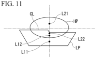
- first light L12 incident on the second boundary surface T2 is guided toward the emission section 8 after being reflected at the second boundary surface T2, and is emitted to the outside of the first lens body 9 from the emission section 8. Further, the light L12 emitted to the outside of the first lens body 9 enters inside of the third lens body 12 from the incidence surface 12a via the air layer K, and is emitted to the outside of the third lens body 12 from the emitting surface 12b. Accordingly, the first light L12 forms a light distribution pattern in the vicinity of the cutoff line CL in the light distribution pattern for a low beam LP shown in Fig. 11 .
- the second light L2 emitted from the above mentioned second light source 3 enters inside of the second lens body 11 from the second incidence section 10.
- the second light L2 entering inside of the second lens body 11 from the second incidence section 10 is guided toward a side in front of the second lens body 11 while being condensed closer to the optical axis AX4 inclined, which is inclined upward diagonally more than the optical axis AX3 of the second light L2 emitted from the second light source 3, in the vertical cross section of the vehicle lighting 1A shown in Fig. 8 .
- second light L21 incident on the first boundary surface T1 passes through the first boundary surface T1, , is guided toward the emission section 8 after being incident into inside of the first lens body 9, and then, is emitted to the outside of the first lens body 9 from the emission section 8. Further, the light L21 emitted to the outside of the first lens body 9 enters inside of the third lens body 12 from the incidence surface 12a via the air layer K, and is emitted to the third lens body 12 from the emitting surface 12b. Accordingly, the second light L21 forms a light distribution pattern above the line H-H in the light distribution pattern for a high beam HP shown in Fig. 11 .
- second light L22 entering the second boundary surface T2 passes through this second boundary surface T2, is guided toward the emission section 8 after being incident on the first lens body 9, and then, is emitted to the outside of the first lens body 9 from the emission section 8. Further, the light L22 emitted to the outside of the first lens body 9 enters inside of the third lens body 12 from the incidence surface 12a via the air layer K, and is emitted to the outside of the third lens body 12 from the emitting surface 12b. Accordingly, the second light L22 forms a light distribution pattern on a lower side in the light distribution pattern for a high beam HP shown in Fig. 11 .
- the second light L22 incident on the second boundary surface T2 approaches a position or a beam angle of the first light L12 reflected at the second boundary surface T2 when passing through the second boundary surface T2. Accordingly, since the second light L22 is emitted below the cutoff line CL of the light distribution pattern for a low beam LP, it is possible to overlap a lower section of the light distribution pattern for a high beam HP shown in Fig. 11 and the cutoff line CL of the light distribution pattern for a low beam LP.
- the first lens body 9 and the second lens body 11 that constitute the projection lens 4 are closely attached or joined to each other without interposing the air layer between the first boundary surface T1 and the second boundary surface T2 by causing the first boundary surface T1 and the second boundary surface T2 to abut each other.
- the headlight 1B for a vehicle of the embodiment it is possible to prevent occurrence of Fresnel loss at between the first boundary surfaces T1 and the second boundary surfaces T2, and it is possible to increase use efficiency of the first light L1 and the second light L2 emitted from the first light source 2 and the second light source 3.
- the vehicle lighting 1B of the embodiment it is possible to share a function of condensing the first light L1 and the second light L2 in the vertical direction of the vehicle lighting 1B and a function of condensing the first light L1 and the second light L2 in the horizontal direction of the vehicle lighting 1B between the emission section 8 and the third lens body 12 of the first lens body 9 by adding the third lens body 12.
- the vehicle lighting to which the present invention is applied is appropriately used for the headlight (headlamp) for a vehicle
- the vehicle lighting to which the present invention is applied is not limited to the above-mentioned front vehicle lighting, and for example, the present invention can also be applied to a rear vehicle lighting such as a rear combination lamp or the like.
- the present invention can be widely applied to the vehicle lighting including the first light source configured to emit first light, a second light source disposed adjacent to the first light source and configured to emit second light in the same direction as the first light, and the projection lens configured to project the first light and the second light in the same direction.
- the color of the first light and the second light is also not limited to the above-mentioned white light, and may be appropriately changed according to a purpose thereof, for example, red light, orange light, or the like. Further, a configuration of causing the first light source and the second light source to selectively emit the first light and the second light having different colors may be provided.
- the present invention can also be applied to the vehicle lighting in which the direction in which the first light source and the second light source are arranged is the horizontal direction of the vehicle lighting and the direction in which the boundary line extends in the vertical direction of the vehicle lighting.
Landscapes
- Engineering & Computer Science (AREA)
- General Engineering & Computer Science (AREA)
- Physics & Mathematics (AREA)
- Microelectronics & Electronic Packaging (AREA)
- Optics & Photonics (AREA)
- Non-Portable Lighting Devices Or Systems Thereof (AREA)
Applications Claiming Priority (2)
| Application Number | Priority Date | Filing Date | Title |
|---|---|---|---|
| JP2020052029A JP7423371B2 (ja) | 2020-03-24 | 2020-03-24 | 車両用灯具 |
| PCT/JP2021/011862 WO2021193588A1 (ja) | 2020-03-24 | 2021-03-23 | 車両用灯具 |
Publications (3)
| Publication Number | Publication Date |
|---|---|
| EP4130569A1 EP4130569A1 (en) | 2023-02-08 |
| EP4130569A4 EP4130569A4 (en) | 2023-10-04 |
| EP4130569B1 true EP4130569B1 (en) | 2025-07-09 |
Family
ID=77849484
Family Applications (1)
| Application Number | Title | Priority Date | Filing Date |
|---|---|---|---|
| EP21776071.9A Active EP4130569B1 (en) | 2020-03-24 | 2021-03-23 | Vehicle lighting |
Country Status (5)
| Country | Link |
|---|---|
| US (1) | US11713858B2 (enExample) |
| EP (1) | EP4130569B1 (enExample) |
| JP (1) | JP7423371B2 (enExample) |
| CN (1) | CN115151756B (enExample) |
| WO (1) | WO2021193588A1 (enExample) |
Families Citing this family (4)
| Publication number | Priority date | Publication date | Assignee | Title |
|---|---|---|---|---|
| JP7540299B2 (ja) * | 2020-10-30 | 2024-08-27 | 市光工業株式会社 | 車両用前照灯 |
| EP4397906A4 (en) * | 2021-08-30 | 2025-01-01 | Koito Manufacturing Co., Ltd. | MICROLENS ARRANGEMENT AND VEHICLE LAMP HOLDER WITH THE MICROLENS ARRANGEMENT |
| JP2024002552A (ja) * | 2022-06-24 | 2024-01-11 | 市光工業株式会社 | 車両用灯具 |
| WO2025047540A1 (ja) * | 2023-08-31 | 2025-03-06 | 株式会社小糸製作所 | 車両用前照灯 |
Family Cites Families (14)
| Publication number | Priority date | Publication date | Assignee | Title |
|---|---|---|---|---|
| JPH08167301A (ja) * | 1994-12-12 | 1996-06-25 | Nippondenso Co Ltd | 車両用前照灯 |
| EP2322848B1 (en) * | 2009-11-12 | 2017-09-27 | Stanley Electric Co., Ltd. | Vehicle light |
| DE112014003720T5 (de) * | 2013-08-12 | 2016-05-19 | Mitsubishi Electric Corporation | Fahrzeugvorderlichtgerät und Lichtleitelement |
| KR101614684B1 (ko) * | 2014-04-24 | 2016-04-22 | 은현수 | 헤드라이트용 플라스틱 아크로매틱렌즈 |
| CN106471309B (zh) * | 2014-07-08 | 2019-04-23 | 三菱电机株式会社 | 前照灯模块 |
| WO2016013340A1 (ja) * | 2014-07-25 | 2016-01-28 | スタンレー電気株式会社 | 車両用灯具 |
| JP6516495B2 (ja) * | 2015-02-13 | 2019-05-22 | 株式会社小糸製作所 | 車両用灯具 |
| CN104832859B (zh) * | 2015-05-29 | 2018-08-07 | 奇瑞汽车股份有限公司 | 一种远近光一体的前照灯 |
| KR20170112253A (ko) * | 2016-03-31 | 2017-10-12 | 에스엘 주식회사 | 차량용 램프 |
| FR3050011A1 (fr) * | 2016-04-11 | 2017-10-13 | Valeo Vision | Module d'emission d'un faisceau lumineux pour projecteur de vehicule automobile |
| KR102195089B1 (ko) * | 2016-09-02 | 2020-12-24 | 가부시키가이샤 고이토 세이사꾸쇼 | 차량용 등기구 |
| KR20190081690A (ko) * | 2017-12-29 | 2019-07-09 | 에스엘 주식회사 | 차량용 램프 |
| FR3084755B1 (fr) * | 2018-08-02 | 2020-12-18 | Valeo Vision | Piece optique comprenant un bloc avec un dioptre formant plieuse pour deux faisceaux |
| JP7142918B2 (ja) | 2019-03-22 | 2022-09-28 | 国立研究開発法人農業・食品産業技術総合研究機構 | 全球測位衛星システム受信機搭載の対空標識 |
-
2020
- 2020-03-24 JP JP2020052029A patent/JP7423371B2/ja active Active
-
2021
- 2021-03-23 WO PCT/JP2021/011862 patent/WO2021193588A1/ja not_active Ceased
- 2021-03-23 US US17/911,427 patent/US11713858B2/en active Active
- 2021-03-23 EP EP21776071.9A patent/EP4130569B1/en active Active
- 2021-03-23 CN CN202180016276.7A patent/CN115151756B/zh active Active
Also Published As
| Publication number | Publication date |
|---|---|
| US11713858B2 (en) | 2023-08-01 |
| EP4130569A4 (en) | 2023-10-04 |
| CN115151756A (zh) | 2022-10-04 |
| EP4130569A1 (en) | 2023-02-08 |
| CN115151756B (zh) | 2024-09-17 |
| JP2021150262A (ja) | 2021-09-27 |
| JP7423371B2 (ja) | 2024-01-29 |
| WO2021193588A1 (ja) | 2021-09-30 |
| US20230100039A1 (en) | 2023-03-30 |
Similar Documents
| Publication | Publication Date | Title |
|---|---|---|
| EP4130569B1 (en) | Vehicle lighting | |
| EP2019257B1 (en) | Vehicle lighting assembly and light guiding lens for use n vehicle lighting assembly | |
| JP5945857B2 (ja) | 車両用前照灯及び導光レンズ | |
| EP3943810B1 (en) | Lighting tool for vehicle | |
| WO2020255845A1 (ja) | 車両用灯具 | |
| EP3943808B1 (en) | Lighting tool for vehicle | |
| JP6725282B2 (ja) | 車両用灯具 | |
| JP6737644B2 (ja) | 車両用灯具 | |
| US10823364B2 (en) | Vehicular lamp | |
| EP3581846B1 (en) | Vehicular lamp | |
| JP7145644B2 (ja) | 車両用灯具 | |
| JP7557337B2 (ja) | 車両用灯具 | |
| JP7619878B2 (ja) | 車両用灯具 | |
| US12066159B2 (en) | Vehicle lamp | |
| JP7139148B2 (ja) | 車両用灯具 | |
| EP3561374B1 (en) | Vehicular lamp | |
| CN221171900U (zh) | 远近光一体车灯光学元件、车灯模组和车辆 | |
| JP7787702B2 (ja) | 車両用灯具 |
Legal Events
| Date | Code | Title | Description |
|---|---|---|---|
| STAA | Information on the status of an ep patent application or granted ep patent |
Free format text: STATUS: THE INTERNATIONAL PUBLICATION HAS BEEN MADE |
|
| PUAI | Public reference made under article 153(3) epc to a published international application that has entered the european phase |
Free format text: ORIGINAL CODE: 0009012 |
|
| STAA | Information on the status of an ep patent application or granted ep patent |
Free format text: STATUS: REQUEST FOR EXAMINATION WAS MADE |
|
| 17P | Request for examination filed |
Effective date: 20220913 |
|
| AK | Designated contracting states |
Kind code of ref document: A1 Designated state(s): AL AT BE BG CH CY CZ DE DK EE ES FI FR GB GR HR HU IE IS IT LI LT LU LV MC MK MT NL NO PL PT RO RS SE SI SK SM TR |
|
| DAV | Request for validation of the european patent (deleted) | ||
| DAX | Request for extension of the european patent (deleted) | ||
| A4 | Supplementary search report drawn up and despatched |
Effective date: 20230904 |
|
| RIC1 | Information provided on ipc code assigned before grant |
Ipc: F21W 102/13 20180101ALN20230829BHEP Ipc: F21S 45/47 20180101ALI20230829BHEP Ipc: F21S 41/32 20180101ALI20230829BHEP Ipc: F21S 41/24 20180101ALI20230829BHEP Ipc: F21S 41/19 20180101ALI20230829BHEP Ipc: F21S 41/143 20180101ALI20230829BHEP Ipc: F21S 41/20 20180101ALI20230829BHEP Ipc: F21S 41/27 20180101ALI20230829BHEP Ipc: F21W 102/135 20180101ALI20230829BHEP Ipc: F21S 41/663 20180101ALI20230829BHEP Ipc: F21S 41/29 20180101ALI20230829BHEP Ipc: F21S 41/265 20180101ALI20230829BHEP Ipc: F21Y 115/10 20160101AFI20230829BHEP |
|
| GRAP | Despatch of communication of intention to grant a patent |
Free format text: ORIGINAL CODE: EPIDOSNIGR1 |
|
| STAA | Information on the status of an ep patent application or granted ep patent |
Free format text: STATUS: GRANT OF PATENT IS INTENDED |
|
| INTG | Intention to grant announced |
Effective date: 20250318 |
|
| RIC1 | Information provided on ipc code assigned before grant |
Ipc: F21W 102/13 20180101ALN20250307BHEP Ipc: F21S 45/47 20180101ALI20250307BHEP Ipc: F21S 41/32 20180101ALI20250307BHEP Ipc: F21S 41/24 20180101ALI20250307BHEP Ipc: F21S 41/19 20180101ALI20250307BHEP Ipc: F21S 41/143 20180101ALI20250307BHEP Ipc: F21S 41/20 20180101ALI20250307BHEP Ipc: F21S 41/27 20180101ALI20250307BHEP Ipc: F21W 102/135 20180101ALI20250307BHEP Ipc: F21S 41/663 20180101ALI20250307BHEP Ipc: F21S 41/29 20180101ALI20250307BHEP Ipc: F21S 41/265 20180101ALI20250307BHEP Ipc: F21Y 115/10 20160101AFI20250307BHEP |
|
| GRAS | Grant fee paid |
Free format text: ORIGINAL CODE: EPIDOSNIGR3 |
|
| GRAA | (expected) grant |
Free format text: ORIGINAL CODE: 0009210 |
|
| STAA | Information on the status of an ep patent application or granted ep patent |
Free format text: STATUS: THE PATENT HAS BEEN GRANTED |
|
| AK | Designated contracting states |
Kind code of ref document: B1 Designated state(s): AL AT BE BG CH CY CZ DE DK EE ES FI FR GB GR HR HU IE IS IT LI LT LU LV MC MK MT NL NO PL PT RO RS SE SI SK SM TR |
|
| REG | Reference to a national code |
Ref country code: GB Ref legal event code: FG4D |
|
| REG | Reference to a national code |
Ref country code: CH Ref legal event code: EP |
|
| REG | Reference to a national code |
Ref country code: IE Ref legal event code: FG4D |
|
| REG | Reference to a national code |
Ref country code: DE Ref legal event code: R096 Ref document number: 602021033856 Country of ref document: DE |
|
| REG | Reference to a national code |
Ref country code: NL Ref legal event code: MP Effective date: 20250709 |
|
| PG25 | Lapsed in a contracting state [announced via postgrant information from national office to epo] |
Ref country code: PT Free format text: LAPSE BECAUSE OF FAILURE TO SUBMIT A TRANSLATION OF THE DESCRIPTION OR TO PAY THE FEE WITHIN THE PRESCRIBED TIME-LIMIT Effective date: 20251110 |
|
| PG25 | Lapsed in a contracting state [announced via postgrant information from national office to epo] |
Ref country code: NL Free format text: LAPSE BECAUSE OF FAILURE TO SUBMIT A TRANSLATION OF THE DESCRIPTION OR TO PAY THE FEE WITHIN THE PRESCRIBED TIME-LIMIT Effective date: 20250709 |
|
| REG | Reference to a national code |
Ref country code: AT Ref legal event code: MK05 Ref document number: 1812108 Country of ref document: AT Kind code of ref document: T Effective date: 20250709 |
|
| PG25 | Lapsed in a contracting state [announced via postgrant information from national office to epo] |
Ref country code: IS Free format text: LAPSE BECAUSE OF FAILURE TO SUBMIT A TRANSLATION OF THE DESCRIPTION OR TO PAY THE FEE WITHIN THE PRESCRIBED TIME-LIMIT Effective date: 20251109 |
|
| PG25 | Lapsed in a contracting state [announced via postgrant information from national office to epo] |
Ref country code: NO Free format text: LAPSE BECAUSE OF FAILURE TO SUBMIT A TRANSLATION OF THE DESCRIPTION OR TO PAY THE FEE WITHIN THE PRESCRIBED TIME-LIMIT Effective date: 20251009 |
|
| REG | Reference to a national code |
Ref country code: LT Ref legal event code: MG9D |
|
| PG25 | Lapsed in a contracting state [announced via postgrant information from national office to epo] |
Ref country code: AT Free format text: LAPSE BECAUSE OF FAILURE TO SUBMIT A TRANSLATION OF THE DESCRIPTION OR TO PAY THE FEE WITHIN THE PRESCRIBED TIME-LIMIT Effective date: 20250709 |
|
| PG25 | Lapsed in a contracting state [announced via postgrant information from national office to epo] |
Ref country code: FI Free format text: LAPSE BECAUSE OF FAILURE TO SUBMIT A TRANSLATION OF THE DESCRIPTION OR TO PAY THE FEE WITHIN THE PRESCRIBED TIME-LIMIT Effective date: 20250709 |
|
| PG25 | Lapsed in a contracting state [announced via postgrant information from national office to epo] |
Ref country code: HR Free format text: LAPSE BECAUSE OF FAILURE TO SUBMIT A TRANSLATION OF THE DESCRIPTION OR TO PAY THE FEE WITHIN THE PRESCRIBED TIME-LIMIT Effective date: 20250709 |