EP4129719B1 - Kältemittelsammelvorrichtung und kältetransportfahrzeug damit - Google Patents
Kältemittelsammelvorrichtung und kältetransportfahrzeug damit Download PDFInfo
- Publication number
- EP4129719B1 EP4129719B1 EP22188391.1A EP22188391A EP4129719B1 EP 4129719 B1 EP4129719 B1 EP 4129719B1 EP 22188391 A EP22188391 A EP 22188391A EP 4129719 B1 EP4129719 B1 EP 4129719B1
- Authority
- EP
- European Patent Office
- Prior art keywords
- refrigerant
- storage
- collecting apparatus
- gas
- transport refrigeration
- Prior art date
- Legal status (The legal status is an assumption and is not a legal conclusion. Google has not performed a legal analysis and makes no representation as to the accuracy of the status listed.)
- Active
Links
Images



Classifications
-
- B—PERFORMING OPERATIONS; TRANSPORTING
- B60—VEHICLES IN GENERAL
- B60H—ARRANGEMENTS OF HEATING, COOLING, VENTILATING OR OTHER AIR-TREATING DEVICES SPECIALLY ADAPTED FOR PASSENGER OR GOODS SPACES OF VEHICLES
- B60H1/00—Heating, cooling or ventilating devices
- B60H1/00357—Air-conditioning arrangements specially adapted for particular vehicles
- B60H1/00364—Air-conditioning arrangements specially adapted for particular vehicles for caravans or trailers
-
- B—PERFORMING OPERATIONS; TRANSPORTING
- B60—VEHICLES IN GENERAL
- B60H—ARRANGEMENTS OF HEATING, COOLING, VENTILATING OR OTHER AIR-TREATING DEVICES SPECIALLY ADAPTED FOR PASSENGER OR GOODS SPACES OF VEHICLES
- B60H1/00—Heating, cooling or ventilating devices
- B60H1/00642—Control systems or circuits; Control members or indication devices for heating, cooling or ventilating devices
- B60H1/00978—Control systems or circuits characterised by failure of detection or safety means; Diagnostic methods
-
- B—PERFORMING OPERATIONS; TRANSPORTING
- B60—VEHICLES IN GENERAL
- B60H—ARRANGEMENTS OF HEATING, COOLING, VENTILATING OR OTHER AIR-TREATING DEVICES SPECIALLY ADAPTED FOR PASSENGER OR GOODS SPACES OF VEHICLES
- B60H1/00—Heating, cooling or ventilating devices
- B60H1/32—Cooling devices
- B60H1/3204—Cooling devices using compression
- B60H1/3225—Cooling devices using compression characterised by safety arrangements, e.g. compressor anti-seizure means or by signalling devices
-
- F—MECHANICAL ENGINEERING; LIGHTING; HEATING; WEAPONS; BLASTING
- F25—REFRIGERATION OR COOLING; COMBINED HEATING AND REFRIGERATION SYSTEMS; HEAT PUMP SYSTEMS; MANUFACTURE OR STORAGE OF ICE; LIQUEFACTION SOLIDIFICATION OF GASES
- F25B—REFRIGERATION MACHINES, PLANTS OR SYSTEMS; COMBINED HEATING AND REFRIGERATION SYSTEMS; HEAT PUMP SYSTEMS
- F25B49/00—Arrangement or mounting of control or safety devices
- F25B49/005—Arrangement or mounting of control or safety devices of safety devices
-
- F—MECHANICAL ENGINEERING; LIGHTING; HEATING; WEAPONS; BLASTING
- F25—REFRIGERATION OR COOLING; COMBINED HEATING AND REFRIGERATION SYSTEMS; HEAT PUMP SYSTEMS; MANUFACTURE OR STORAGE OF ICE; LIQUEFACTION SOLIDIFICATION OF GASES
- F25D—REFRIGERATORS; COLD ROOMS; ICE-BOXES; COOLING OR FREEZING APPARATUS NOT OTHERWISE PROVIDED FOR
- F25D29/00—Arrangement or mounting of control or safety devices
- F25D29/006—Safety devices
-
- F—MECHANICAL ENGINEERING; LIGHTING; HEATING; WEAPONS; BLASTING
- F25—REFRIGERATION OR COOLING; COMBINED HEATING AND REFRIGERATION SYSTEMS; HEAT PUMP SYSTEMS; MANUFACTURE OR STORAGE OF ICE; LIQUEFACTION SOLIDIFICATION OF GASES
- F25B—REFRIGERATION MACHINES, PLANTS OR SYSTEMS; COMBINED HEATING AND REFRIGERATION SYSTEMS; HEAT PUMP SYSTEMS
- F25B2400/00—Component parts or details not otherwise provided for in this subclass
- F25B2400/12—Inflammable refrigerants
- F25B2400/121—Inflammable refrigerants using R1234
-
- F—MECHANICAL ENGINEERING; LIGHTING; HEATING; WEAPONS; BLASTING
- F25—REFRIGERATION OR COOLING; COMBINED HEATING AND REFRIGERATION SYSTEMS; HEAT PUMP SYSTEMS; MANUFACTURE OR STORAGE OF ICE; LIQUEFACTION SOLIDIFICATION OF GASES
- F25B—REFRIGERATION MACHINES, PLANTS OR SYSTEMS; COMBINED HEATING AND REFRIGERATION SYSTEMS; HEAT PUMP SYSTEMS
- F25B2400/00—Component parts or details not otherwise provided for in this subclass
- F25B2400/23—Separators
-
- F—MECHANICAL ENGINEERING; LIGHTING; HEATING; WEAPONS; BLASTING
- F25—REFRIGERATION OR COOLING; COMBINED HEATING AND REFRIGERATION SYSTEMS; HEAT PUMP SYSTEMS; MANUFACTURE OR STORAGE OF ICE; LIQUEFACTION SOLIDIFICATION OF GASES
- F25B—REFRIGERATION MACHINES, PLANTS OR SYSTEMS; COMBINED HEATING AND REFRIGERATION SYSTEMS; HEAT PUMP SYSTEMS
- F25B2500/00—Problems to be solved
- F25B2500/22—Preventing, detecting or repairing leaks of refrigeration fluids
- F25B2500/222—Detecting refrigerant leaks
-
- F—MECHANICAL ENGINEERING; LIGHTING; HEATING; WEAPONS; BLASTING
- F25—REFRIGERATION OR COOLING; COMBINED HEATING AND REFRIGERATION SYSTEMS; HEAT PUMP SYSTEMS; MANUFACTURE OR STORAGE OF ICE; LIQUEFACTION SOLIDIFICATION OF GASES
- F25D—REFRIGERATORS; COLD ROOMS; ICE-BOXES; COOLING OR FREEZING APPARATUS NOT OTHERWISE PROVIDED FOR
- F25D2400/00—General features of, or devices for refrigerators, cold rooms, ice-boxes, or for cooling or freezing apparatus not covered by any other subclass
- F25D2400/24—Protection against refrigerant explosions
Definitions
- the present invention relates to a refrigerant collecting apparatus and a transport refrigeration vehicle including the same.
- a refrigeration apparatus including a refrigerant circuit that performs a freezing cycle with a refrigerant circulated therein in order to cool the inside of a storage such as a storehouse for refrigerating and freezing food and the like or a transport container is provided in the storage.
- Japanese Patent Laid-Open No. 2020-101342 discloses a CA (Collecting Apparatus) device that includes a collection tank for collecting a leaking refrigerant.
- the CA device is configured such that a CA controller adapted to detect whether or not a refrigerant has leaked inside a storage and cause the CA device to perform a refrigerant discharging operation in a case in which a refrigerant has leaked controls opening and closing of an air pump and each control valve, and the refrigerant leaking inside the storage is compressed along with the air in the storage, is then discharged to the outside of the storage, and is collected by the collection tank.
- the CA device is for safely discharging the refrigerant leaking inside the storage from the inside of the storage by operating such that the refrigerant leaking from the refrigerant circuit is collected in the collection.
- Japanese Patent Application Laid-Open No. 2020-101342 is an example of the related art.
- An object of the present invention which has been made in view of such circumstances, is to provide a refrigerant collecting apparatus capable of effectively collecting a leaking refrigerant from a storage and a transport refrigeration vehicle including the same.
- a refrigerant collecting apparatus includes: a first pipe that transports a fluid containing a refrigerant that is present inside a storage of a transport refrigeration vehicle including a transport refrigeration unit; a compressor that compresses the fluid guided from the first pipe; a condenser that condenses the refrigerant contained in the fluid guided from the compressor; and a gas-liquid separator that performs gas-liquid separation on the fluid guided from the condenser.
- Fig. 1 illustrates an overview configuration of a transport refrigeration vehicle 1 according to an embodiment of the present invention.
- the transport refrigeration vehicle 1 includes a tractor (vehicle main body) 10 and a transport refrigeration unit 11 (dashed line in Fig. 1 ) connected behind the tractor 10.
- the transport refrigeration unit 11 includes a storage (freezing container) 12, an evaporator unit 13, a condensing unit 14, a leakage detection means 15, and a refrigerant collecting apparatus 20.
- a freezing cycle is configured by the evaporator unit 13, the condensing unit 14, and a refrigerant pipe, which is not illustrated, being connected to each other.
- a storage 12 is a container that is mounted on a loading platform of a transport vehicle, is used to accommodate a load to be transported, and can be tightly closed.
- the storage 12 is provided with an evaporator unit 13 and a leakage detection means 15.
- the temperature of air inside the storage 12 is decreased through heat exchange between an evaporator (not illustrated) of the evaporator unit 13 and the air inside the storage 12.
- the evaporator unit 13 accommodates, in a case, a fan (not illustrated), an expansion valve (not illustrated) that narrows down a refrigerant, an evaporator that evaporates the refrigerant guided from the expansion valve, and the like.
- the evaporator is, for example, a heat exchanger that includes a heat transfer tube inside which the refrigerant is distributed and a fin that is attached to the heat transfer tube. Heat is taken away from the air in the storage and the air inside the storage is cooled by the evaporator evaporating the refrigerant.
- An outer shell of the condensing unit 14 is formed from a box-shaped case that is fixed to a chassis of the transport refrigeration vehicle 1, and a fan (not illustrated), a compressor (not illustrated) that compresses the refrigerant, a condenser that condenses a high-temperature high-pressure refrigerant fed from the compressor, a motor (not illustrated) that drives the compressor, an engine (not illustrated), and/or the like are accommodated in the case.
- the condenser is, for example, a heat exchanger that includes a heat transfer tube inside which the refrigerant is distributed and a fin that is attached to the heat transfer tube. The heat is discharged to the outside air by the condenser condensing the refrigerant.
- the refrigerant circulated in the evaporator unit 13 and the condensing unit 14 is a mildly flammable refrigerant.
- the mildly flammable refrigerant means refrigerant that shows mild flammability among flammable refrigerants.
- the mildly flammable refrigerant includes R32 that is a refrigerant resulting from hydrofluorocarbon (HFC), R1234yf and R1234ze that are refrigerants resulting from hydrofluoroolefin (HFO), and the like.
- the mildly flammable refrigerant is not limited to the aforementioned substances, and refrigerants categorized in SubCLASS2L by ISO817 which is an international standard and refrigerants categorized in SubCLASS2L by ASHRAE34 which is a standard of American Society of Heating, Refrigerating and Air-Conditioning Engineers also correspond thereto.
- the leakage detection means 15 detects whether or not the refrigerant has leaked inside the storage 12. Specifically, in a case in which the concentration of the refrigerant inside the storage 12 is greater than a predetermined amount set in advance, the leakage detection means 15 detects that the refrigerant has leaked inside the storage 12 in an example.
- the leakage detection means 15 is a leakage sensor. As long as it is a means capable of performing refrigerant leakage detection, the leakage detection means 15 may use any of a mechanical system, an electrical system, and an optical system.
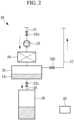
- Fig. 2 is a diagram illustrating a configuration of the refrigerant collecting apparatus 20 according to a first embodiment of the present invention.
- the refrigerant collecting apparatus 20 includes a first pipe 21, an opening/closing valve 22a, a compressor 23, a condenser 24, and a gas-liquid separator 25.
- the refrigerant collecting apparatus 20 collects a fluid containing the refrigerant that is present inside the storage 12 in addition to the air inside the storage 12 when the refrigerant leaks inside the storage 12.
- the position where the refrigerant collecting apparatus 20 is mounted is not limited to the position illustrated in Fig. 1 and may be appropriately changed as long as it is possible to include the refrigerant collecting apparatus 20 in the transport refrigeration vehicle 1.
- the first pipe 21 includes one opening connected to the storage 12 mounted on the transport refrigeration vehicle 1 and is connected to the gas-liquid separator 25 via the compressor 23 and the condenser 24.
- the fluid containing the refrigerant leaking inside the storage 12 and collected by the refrigerant collecting apparatus 20 is transported to the gas-liquid separator 25 via the first pipe 21, the compressor 23, and the condenser 24.
- the opening/closing valve 22a is provided in the first pipe 21 and switches opening/closing of the opening/closing valve 22a to establish whether or not to transport the refrigerant to the inside of the first pipe 21.
- the compressor 23 compresses the fluid containing the refrigerant and guided from the first pipe 21 and increases the temperature and the pressure thereof. The compressor 23 then ejects the high-temperature and high-pressure fluid containing the refrigerant to the condenser 24.
- a scroll compressor, a rotary compressor, or the like is mainly used as the compressor 23, the type of the compressor 23 is not limited thereto.
- the condenser 24 condenses the refrigerant by causing the fluid containing the refrigerant and ejected from the compressor 23 to perform heat exchange with external air. Then, the refrigerant contained in the fluid is condensed, and the state of the refrigerant is thus changed, thereby generating a liquid refrigerant LR.
- heat exchange based on air cooling is exemplified as a method for the heat exchange in the present embodiment, the method is not limited thereto.
- the gas-liquid separator 25 separates the fluid transported from the condenser 24 into gas and the liquid refrigerant LR. Then, the gas separated by the gas-liquid separator 25 passes through a second pipe 27 and is transported to the inside of the storage 12 via an opening/closing valve 22b. The liquid refrigerant LR separated by the gas-liquid separator 25 passes through a third pipe 28 and is transported to a pressure container 29 via an opening/closing valve 22c.
- the gas-liquid separator 25 may be any gas-liquid separator as long as it can separate the fluid into gas and the liquid refrigerant LR, and any of a settled separation scheme, a distilled separation scheme, a centrifugal separation scheme, an adsorption separation scheme, and the like may be used.
- the opening/closing valve 22b is provided in the second pipe 27.
- the control unit 26 switches opening/closing of the opening/closing valve 22b to establish whether or not to transport gas to the inside of the second pipe 27.
- the third pipe 28 is connected to each of the gas-liquid separator 25 and the pressure container 29, and the liquid refrigerant LR separated by the gas-liquid separator 25 is transported to the pressure container 29 via the third pipe 28.
- the opening/closing valve 22c is provided in the third pipe 28.
- the control unit 26 switches opening/closing of the opening/closing valve 22c to establish whether or not to transport the liquid refrigerant LR to the inside of the third pipe 28.
- the pressure container 29 retains the liquid refrigerant LR transported from the gas-liquid separator 25 via the third pipe 28.
- the pressure container 29 is not limited to the tightly closed container and may be any pressure container as long as it is possible to retain the liquid refrigerant LR at a constant pressure.
- the control unit 26 switches operations of the refrigerant collecting apparatus 20 and controls operations of the leakage detection means 15, the compressor 23, and the condenser 24.
- the control unit 26 is a computer system (calculator system) and includes, for example, a CPU, a read only memory (ROM) that stores programs and the like to be executed by the CPU, a random access memory (RAM) that functions as a work area when each program is executed, a hard disk drive (HDD) that serves as a large-capacity storage device, and a communication unit that is for connection to a network or the like.
- a solid state drive SSD
- Each component is connected via a bus.
- the control unit 26 may include an input unit including a keyboard, a mouse, and the like, a display unit including a liquid crystal display device or the like that displays data, and the like.
- a storage medium that stores the programs and the like executed by the CPU is not limited to the ROM.
- the storage medium may be another auxiliary storage device such as a magnetic disk, a magneto-optical disk, or a semiconductor memory.
- the computer-readable storage medium is a magnetic disk, a magneto-optical disk, a CD-ROM, a DVD-ROM, a semiconductor memory, or the like.
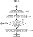
- FIGs. 3 and 4 are flowcharts illustrating an example of a procedure of the refrigerant collection processing according to the present embodiment. The following refrigerant collection processing is started in accordance with a timing at which the leakage detection means 15 detects that the refrigerant has leaked inside the storage 12, for example.
- the leakage detection means 15 provided inside the storage 12 detects whether or not the refrigerant has leaked inside the storage 12 (S101). In a case in which the leakage detection means 15 does not detect that the refrigerant has leaked inside the storage 12 (S101: NO), the processing in S101 is repeatedly performed until the leakage detection means 15 detects that the refrigerant has leaked inside the storage 12.
- the control unit 26 opens each of the opening/closing valves 22a, 22b, and 22c (S102) and activates each of the compressor 23, the condenser 24, and the gas-liquid separator 25. In this manner, the fluid containing the refrigerant leaking in the storage 12 is guided to the compressor 23 via the first pipe 21.
- the compressor 23 compresses the fluid containing the refrigerant and guided to the compressor 23 and increases the temperature and the pressure thereof (S103). Then, the high-temperature and high-pressure fluid containing the refrigerant is ejected from the compressor 23 to the condenser 24.
- the condenser 24 condenses the refrigerant by causing the high-temperature and high-pressure fluid containing the refrigerant and ejected from the compressor 23 to perform heat exchange with external air and changes the state of the refrigerant contained in the fluid into a liquid refrigerant LR (S104). Then, the fluid containing the liquid refrigerant LR is transported to the gas-liquid separator 25.
- the gas-liquid separator 25 separates the fluid transported from the condenser 24 into gas and the liquid refrigerant LR (S105). Then, the gas separated by the gas-liquid separator 25 is transported to the inside of the storage 12 via the second pipe 27 (S106). The liquid refrigerant LR separated by the gas-liquid separator 25 is transported to the pressure container 29 via the third pipe 28 (S107). The liquid refrigerant LR transported to the pressure container 29 is retained inside the pressure container 29.
- the leakage detection means 15 detects that the refrigerant has leaked inside the storage 12 (S108: YES)
- the refrigerant collecting apparatus 20 continues the processing in S103 to S107.
- the control unit 26 closes each of the opening/closing valves 22a, 22b, and 22c (S109) and stops each of the compressor 23, the condenser 24, and the gas-liquid separator 25.
- the refrigerant collecting apparatus 20 is included in the transport refrigeration vehicle 1, the refrigerant collecting apparatus 20 is activated by the control unit 26 when the leakage detection means 15 detects leakage of the refrigerant inside the storage 12, and it is thus possible to automatically collect the refrigerant.
- the second embodiment is characterized in that the refrigerant collecting apparatus 20 is not included in the transport refrigeration vehicle 1 and is attachable/detachable to/from the transport refrigeration vehicle 1. Specifically, the refrigerant collecting apparatus 20 is mounted on or removed from the transport refrigeration vehicle 1 by a driver or a service person when the engine of the transport refrigeration vehicle 1 is stopped.
- the other configurations included in the transport refrigeration vehicle 1 are the same as those in the first embodiment.
- the refrigerant collecting apparatus 20 in the second embodiment is attachable/detachable to/from the transport refrigeration vehicle 1 and is not attached to the transport refrigeration vehicle 1 when the transport refrigeration vehicle 1 is traveling.
- the refrigerant collecting apparatus 20 is mounted on the transport refrigeration vehicle 1 by a driver or a service person in a case in which the leakage detection means 15 detects that the refrigerant has leaked inside the storage 12 when the transport refrigeration vehicle 1 is stopping.
- the refrigerant collecting apparatus 20 mounted in the transport refrigeration vehicle 1 is activated by the driver or the service person and collects the fluid containing the refrigerant that has leaked inside the storage 12.
- the driver or the service person stops the refrigerant collecting apparatus 20 and removes the refrigerant collecting apparatus 20 from the transport refrigeration vehicle 1.
- the driver or the service person can determine whether or not to mount or remove the refrigerant collecting apparatus 20 and whether or not to collect the refrigerant inside the storage 12 when the engine of the transport refrigeration vehicle 1 is stopping. It is thus possible to appropriately collect the refrigerant leaking inside the storage 12 in consideration of the external environment and the like of the transport refrigeration vehicle 1.
- the refrigerant collecting apparatus 20 is a refrigerant collecting apparatus 20 that can supply the liquid refrigerant LR retained in the pressure container 29 to the condensing unit 14.
- Fig. 5 is a diagram illustrating an example of a transport refrigeration vehicle 1 according to the third embodiment.
- the transport refrigeration vehicle 1 illustrated in Fig. 5 is characterized by a condensing unit 14 and a refrigerant collecting apparatus 20 being connected with a fourth pipe 30.
- the other configurations included in the transport refrigeration vehicle 1 are the same as those in the first embodiment.
- the condensing unit 14 includes a remaining amount detection means 31 that detects the remaining amount of the refrigerant inside the condensing unit 14.
- the remaining amount detection means 31 is a level sensor that detects the remaining amount of the liquid refrigerant LR inside the condensing unit 14, for example.
- the control unit 26 drives a pump (not illustrated) for transporting the liquid refrigerant on the basis of the detection result of the remaining amount detection means 31.
- the liquid refrigerant LR may be transported by switching an opening/closing state of an opening/closing valve (not illustrated) provided in the fourth pipe 30 instead of driving the pump.
- the liquid refrigerant LR retained in the pressure container 29 is supplied to the condensing unit 14 via the fourth pipe 30 by the control unit 26 driving the pump for transporting the refrigerant or the opening/closing valve on the basis of the detection result of the remaining amount detection means 31.
- the supply of the liquid refrigerant LR from the pressure container 29 to the condensing unit 14 is stopped by the supply of the liquid refrigerant LR from the pressure container 29 to the condensing unit 14 being performed for a certain period of time or by the control unit 26 stopping the pump on the basis of the detection result of the remaining amount detection means 31.
- the opening/closing valve provided in the fourth pipe 30 may be an expansion valve (not illustrated) for reducing the pressure of the liquid refrigerant at a pressure that has increased inside the pressure container.
- the liquid refrigerant LR is transported to the condensing unit 14 in a state in which it is likely to be evaporated by the expansion valve reducing the pressure of the liquid refrigerant LR.
- a mechanism for reducing the pressure of the liquid refrigerant LR is not limited to this example, and another scheme may be used.
- the refrigerant collecting apparatus 20 collects the refrigerant that has leaked inside the storage 12 and supplies the liquid refrigerant LR retained in the pressure container 29 to the condensing unit 14. Therefore, the refrigerant does not deplete inside the evaporator unit 13 and the condensing unit 14 even in a case in which the refrigerant continuously leaks to the inside of the storage 12, and it is thus possible to maintain a low-temperature atmosphere inside the storage 12 even in a case in which a load to be transported is transported for a long period of time.
- the refrigerant collecting apparatus and the transport refrigeration vehicle including the same according to the present invention described above are understood as follows, for example.
- a refrigerant collecting apparatus 20 includes: a first pipe 21 that transports a fluid containing a refrigerant that is present inside a storage 12 of a transport refrigeration vehicle 1 including a transport refrigeration unit 11; a compressor 23 that compresses the fluid guided from the first pipe; a condenser 24 that condenses the refrigerant contained in the fluid guided from the compressor; and a gas-liquid separator 25 that performs gas-liquid separation on the fluid guided from the condenser.
- the refrigerant collecting apparatus collects the fluid inside the storage of the refrigeration unit using the first pipe and compresses the fluid guided from the first pipe by the compressor in a case in which the refrigerant leaks. Then, the fluid at the increased pressure is condensed by the condenser, and the condensed fluid is separated into gas and a liquid refrigerant by the gas-liquid separator. It is possible to reduce the concentration of the refrigerant inside the storage of the transport refrigeration unit by collecting the fluid containing the refrigerant inside the storage.
- the refrigerant collecting apparatus may include a second pipe 27 that transports the gas separated by the gas-liquid separator to the inside of the storage.
- the gas separated by the gas-liquid separator is transported to the inside of the storage via the second pipe connected to the gas-liquid separator.
- the gas separated by the gas-liquid separator is transported to the inside of the storage via the second pipe connected to the gas-liquid separator.
- the refrigerant collecting apparatus may include a pressure container 29 that accommodates the liquid refrigerant separated by the gas-liquid separator.
- the liquid refrigerant separated by the gas-liquid separator is transported to the pressure container.
- the refrigerant can be reused.
- the refrigerant collecting apparatus may include a refrigerant leakage detector 15 that detects leakage of the refrigerant inside the storage.
- the refrigerant leakage detector detects leakage of the refrigerant inside the storage. In this manner, it is possible to collect the refrigerant only in a case in which leakage of the refrigerant in the storage occurs and thereby to drive the refrigerant collecting apparatus only when it is necessary to collect the refrigerant. Therefore, it is possible to reduce energy when the refrigerant collecting apparatus is driven.
Landscapes
- Engineering & Computer Science (AREA)
- Physics & Mathematics (AREA)
- Mechanical Engineering (AREA)
- Thermal Sciences (AREA)
- General Engineering & Computer Science (AREA)
- Chemical & Material Sciences (AREA)
- Combustion & Propulsion (AREA)
- Devices That Are Associated With Refrigeration Equipment (AREA)
Claims (5)
- Kältemittelsammelvorrichtung (20), umfassend:ein erstes Rohr (21), das dazu ausgestaltet ist, ein Fluid zu transportieren, das ein Kältemittel enthält, das im Inneren eines Speichers (12) eines Kühltransportfahrzeugs (1), das eine Kühltransporteinheit (11) beinhaltet, vorhanden ist,einen Verdichter (23), der dazu ausgestaltet ist, das Fluid, das von dem ersten Rohr weg geleitet wird, zu verdichten,einen Kondensator (24), der dazu ausgestaltet ist, das Kältemittel, das in dem Fluid enthalten ist, das von dem Verdichter weg geleitet wird, zu kondensieren, undeinen Gas-Flüssigkeitsabscheider (25), der dazu ausgestaltet ist, eine Gas-Flüssigkeitsabscheidung an dem Fluid, das von dem Kondensator weg geleitet wird, durchzuführen.
- Kältemittelsammelvorrichtung (20) nach Anspruch 1, ferner umfassend:
ein zweites Rohr (27), das dazu ausgestaltet ist, Gas, das von dem Gas-Flüssigkeitsabscheider abgeschieden wurde, in das Innere des Speichers zu transportieren. - Kältemittelsammelvorrichtung (20) nach Anspruch 1 oder 2, ferner umfassend:
einen Druckbehälter (29), der ein flüssiges Kältemittel, das von dem Gas-Flüssigkeitsabscheider abgeschieden wurde, beherbergt. - Kältemittelsammelvorrichtung (20) nach einem der Ansprüche 1 bis 3, ferner umfassend:
eine Kältemittelleck-Erkennungsvorrichtung (15), die ein Leck des Kältemittels im Inneren des Speichers (12) erkennt. - Kühltransportfahrzeug, umfassend:
die Kältemittelsammelvorrichtung (20) nach einem der Ansprüche 1 bis 4.
Applications Claiming Priority (1)
| Application Number | Priority Date | Filing Date | Title |
|---|---|---|---|
| JP2021127950A JP7661177B2 (ja) | 2021-08-04 | 2021-08-04 | 冷媒回収装置及びこれを備えた輸送用冷凍車両 |
Publications (3)
| Publication Number | Publication Date |
|---|---|
| EP4129719A1 EP4129719A1 (de) | 2023-02-08 |
| EP4129719C0 EP4129719C0 (de) | 2024-05-01 |
| EP4129719B1 true EP4129719B1 (de) | 2024-05-01 |
Family
ID=82786830
Family Applications (1)
| Application Number | Title | Priority Date | Filing Date |
|---|---|---|---|
| EP22188391.1A Active EP4129719B1 (de) | 2021-08-04 | 2022-08-02 | Kältemittelsammelvorrichtung und kältetransportfahrzeug damit |
Country Status (2)
| Country | Link |
|---|---|
| EP (1) | EP4129719B1 (de) |
| JP (1) | JP7661177B2 (de) |
Family Cites Families (6)
| Publication number | Priority date | Publication date | Assignee | Title |
|---|---|---|---|---|
| JPH0411920A (ja) * | 1990-04-26 | 1992-01-16 | Mitsubishi Heavy Ind Ltd | 潜水船用炭酸ガス処理装置 |
| JPH062994A (ja) * | 1992-06-19 | 1994-01-11 | Hitachi Bill Shisetsu Eng Kk | 冷媒回収用の温度,圧力調整装置、および同調整方法 |
| JP2004353895A (ja) * | 2003-05-27 | 2004-12-16 | Sanden Corp | 車両用空調装置 |
| JP7148798B2 (ja) | 2018-12-25 | 2022-10-06 | ダイキン工業株式会社 | 庫内空気調整装置 |
| WO2020194527A1 (ja) * | 2019-03-26 | 2020-10-01 | 三菱電機株式会社 | 冷凍サイクル装置の室外ユニットおよび室内ユニット |
| US11407287B2 (en) * | 2019-04-11 | 2022-08-09 | Carrier Corporation | Refrigerant leak sensor pre-trip sequence and diagnostics |
-
2021
- 2021-08-04 JP JP2021127950A patent/JP7661177B2/ja active Active
-
2022
- 2022-08-02 EP EP22188391.1A patent/EP4129719B1/de active Active
Also Published As
| Publication number | Publication date |
|---|---|
| EP4129719C0 (de) | 2024-05-01 |
| JP2023022889A (ja) | 2023-02-16 |
| JP7661177B2 (ja) | 2025-04-14 |
| EP4129719A1 (de) | 2023-02-08 |
Similar Documents
| Publication | Publication Date | Title |
|---|---|---|
| US11635239B2 (en) | Refrigeration system with purge and acid filter | |
| EP2741028B1 (de) | Kühlvorrichtung | |
| US5694779A (en) | Refrigerator and condenser | |
| CN101213410B (zh) | 冷冻装置 | |
| EP2526354B1 (de) | System und verfahren zum spülen von klimaanlagensystemen | |
| KR101214755B1 (ko) | 냉매 회수 시스템 및 이에 이용되는 냉매 회수 장치 | |
| JP2014095484A (ja) | 冷却装置 | |
| EP3711843B1 (de) | Verfahren und system zur rückgewinnung und reinigung eines gasförmigen sterilisationsmittels | |
| EP4129719B1 (de) | Kältemittelsammelvorrichtung und kältetransportfahrzeug damit | |
| KR101401877B1 (ko) | 차량용 에어컨시스템의 냉매 자동 교환장치 | |
| KR20150119711A (ko) | 폐냉매 재사용 정제 시스템 | |
| US11813925B2 (en) | Methods and systems for maintaining cargo at an ultra-low temperature over an extended period of time | |
| EP2801772B1 (de) | Kühlvorrichtung und -verfahren zur erkennung der abfüllung eines falschen kühlmittels | |
| KR101152274B1 (ko) | 코일이 내장된 냉매회수탱크가 포함된 냉매회수장치 | |
| JP2004322933A (ja) | 車両用冷凍サイクル装置 | |
| US11819800B2 (en) | Method and system for recovering and purifying a gaseous sterilizing agent | |
| US8297063B2 (en) | Method for servicing a refrigeration system | |
| EP2999931B1 (de) | Thermochemisches verstärktes kühlsystem | |
| KR101248343B1 (ko) | 듀얼 타입 냉매 회수 시스템 및 이에 이용되는 듀얼 타입 냉매 회수 장치 | |
| JP3846753B2 (ja) | 冷凍装置 | |
| JP3785739B2 (ja) | 冷凍庫 | |
| US11819801B2 (en) | Method and system for recovering and purifying a gaseous sterilizing agent | |
| Hwang et al. | Oil circulation behavior in low temperature CO2 climate control systems | |
| JP2011065429A (ja) | 自動販売機 | |
| JP5240017B2 (ja) | 自動販売機 |
Legal Events
| Date | Code | Title | Description |
|---|---|---|---|
| PUAI | Public reference made under article 153(3) epc to a published international application that has entered the european phase |
Free format text: ORIGINAL CODE: 0009012 |
|
| STAA | Information on the status of an ep patent application or granted ep patent |
Free format text: STATUS: THE APPLICATION HAS BEEN PUBLISHED |
|
| AK | Designated contracting states |
Kind code of ref document: A1 Designated state(s): AL AT BE BG CH CY CZ DE DK EE ES FI FR GB GR HR HU IE IS IT LI LT LU LV MC MK MT NL NO PL PT RO RS SE SI SK SM TR |
|
| STAA | Information on the status of an ep patent application or granted ep patent |
Free format text: STATUS: REQUEST FOR EXAMINATION WAS MADE |
|
| 17P | Request for examination filed |
Effective date: 20230608 |
|
| RBV | Designated contracting states (corrected) |
Designated state(s): AL AT BE BG CH CY CZ DE DK EE ES FI FR GB GR HR HU IE IS IT LI LT LU LV MC MK MT NL NO PL PT RO RS SE SI SK SM TR |
|
| GRAP | Despatch of communication of intention to grant a patent |
Free format text: ORIGINAL CODE: EPIDOSNIGR1 |
|
| STAA | Information on the status of an ep patent application or granted ep patent |
Free format text: STATUS: GRANT OF PATENT IS INTENDED |
|
| RIC1 | Information provided on ipc code assigned before grant |
Ipc: F25B 49/00 20060101ALI20231102BHEP Ipc: F25D 29/00 20060101ALI20231102BHEP Ipc: B60H 1/32 20060101ALI20231102BHEP Ipc: B60H 1/00 20060101AFI20231102BHEP |
|
| INTG | Intention to grant announced |
Effective date: 20231127 |
|
| RAP3 | Party data changed (applicant data changed or rights of an application transferred) |
Owner name: MITSUBISHI HEAVY INDUSTRIES THERMAL SYSTEMS, LTD. |
|
| RIN1 | Information on inventor provided before grant (corrected) |
Inventor name: KELLEN, JOHNSON Inventor name: HASHIZUME, YOSHIHIRO Inventor name: KOBAYASHI, NAOKI Inventor name: MARUTA, YOSUKE |
|
| GRAS | Grant fee paid |
Free format text: ORIGINAL CODE: EPIDOSNIGR3 |
|
| GRAA | (expected) grant |
Free format text: ORIGINAL CODE: 0009210 |
|
| STAA | Information on the status of an ep patent application or granted ep patent |
Free format text: STATUS: THE PATENT HAS BEEN GRANTED |
|
| AK | Designated contracting states |
Kind code of ref document: B1 Designated state(s): AL AT BE BG CH CY CZ DE DK EE ES FI FR GB GR HR HU IE IS IT LI LT LU LV MC MK MT NL NO PL PT RO RS SE SI SK SM TR |
|
| REG | Reference to a national code |
Ref country code: GB Ref legal event code: FG4D |
|
| REG | Reference to a national code |
Ref country code: CH Ref legal event code: EP |
|
| REG | Reference to a national code |
Ref country code: IE Ref legal event code: FG4D |
|
| REG | Reference to a national code |
Ref country code: DE Ref legal event code: R096 Ref document number: 602022003191 Country of ref document: DE |
|
| U01 | Request for unitary effect filed |
Effective date: 20240522 |
|
| U07 | Unitary effect registered |
Designated state(s): AT BE BG DE DK EE FI FR IT LT LU LV MT NL PT SE SI Effective date: 20240531 |
|
| U20 | Renewal fee for the european patent with unitary effect paid |
Year of fee payment: 3 Effective date: 20240808 |
|
| PG25 | Lapsed in a contracting state [announced via postgrant information from national office to epo] |
Ref country code: IS Free format text: LAPSE BECAUSE OF FAILURE TO SUBMIT A TRANSLATION OF THE DESCRIPTION OR TO PAY THE FEE WITHIN THE PRESCRIBED TIME-LIMIT Effective date: 20240901 |
|
| PG25 | Lapsed in a contracting state [announced via postgrant information from national office to epo] |
Ref country code: HR Free format text: LAPSE BECAUSE OF FAILURE TO SUBMIT A TRANSLATION OF THE DESCRIPTION OR TO PAY THE FEE WITHIN THE PRESCRIBED TIME-LIMIT Effective date: 20240501 |
|
| PG25 | Lapsed in a contracting state [announced via postgrant information from national office to epo] |
Ref country code: GR Free format text: LAPSE BECAUSE OF FAILURE TO SUBMIT A TRANSLATION OF THE DESCRIPTION OR TO PAY THE FEE WITHIN THE PRESCRIBED TIME-LIMIT Effective date: 20240802 |
|
| PG25 | Lapsed in a contracting state [announced via postgrant information from national office to epo] |
Ref country code: ES Free format text: LAPSE BECAUSE OF FAILURE TO SUBMIT A TRANSLATION OF THE DESCRIPTION OR TO PAY THE FEE WITHIN THE PRESCRIBED TIME-LIMIT Effective date: 20240501 |
|
| PG25 | Lapsed in a contracting state [announced via postgrant information from national office to epo] |
Ref country code: PL Free format text: LAPSE BECAUSE OF FAILURE TO SUBMIT A TRANSLATION OF THE DESCRIPTION OR TO PAY THE FEE WITHIN THE PRESCRIBED TIME-LIMIT Effective date: 20240501 |
|
| PG25 | Lapsed in a contracting state [announced via postgrant information from national office to epo] |
Ref country code: PL Free format text: LAPSE BECAUSE OF FAILURE TO SUBMIT A TRANSLATION OF THE DESCRIPTION OR TO PAY THE FEE WITHIN THE PRESCRIBED TIME-LIMIT Effective date: 20240501 Ref country code: NO Free format text: LAPSE BECAUSE OF FAILURE TO SUBMIT A TRANSLATION OF THE DESCRIPTION OR TO PAY THE FEE WITHIN THE PRESCRIBED TIME-LIMIT Effective date: 20240801 Ref country code: IS Free format text: LAPSE BECAUSE OF FAILURE TO SUBMIT A TRANSLATION OF THE DESCRIPTION OR TO PAY THE FEE WITHIN THE PRESCRIBED TIME-LIMIT Effective date: 20240901 Ref country code: HR Free format text: LAPSE BECAUSE OF FAILURE TO SUBMIT A TRANSLATION OF THE DESCRIPTION OR TO PAY THE FEE WITHIN THE PRESCRIBED TIME-LIMIT Effective date: 20240501 Ref country code: GR Free format text: LAPSE BECAUSE OF FAILURE TO SUBMIT A TRANSLATION OF THE DESCRIPTION OR TO PAY THE FEE WITHIN THE PRESCRIBED TIME-LIMIT Effective date: 20240802 Ref country code: ES Free format text: LAPSE BECAUSE OF FAILURE TO SUBMIT A TRANSLATION OF THE DESCRIPTION OR TO PAY THE FEE WITHIN THE PRESCRIBED TIME-LIMIT Effective date: 20240501 Ref country code: RS Free format text: LAPSE BECAUSE OF FAILURE TO SUBMIT A TRANSLATION OF THE DESCRIPTION OR TO PAY THE FEE WITHIN THE PRESCRIBED TIME-LIMIT Effective date: 20240801 |
|
| PG25 | Lapsed in a contracting state [announced via postgrant information from national office to epo] |
Ref country code: CZ Free format text: LAPSE BECAUSE OF FAILURE TO SUBMIT A TRANSLATION OF THE DESCRIPTION OR TO PAY THE FEE WITHIN THE PRESCRIBED TIME-LIMIT Effective date: 20240501 |
|
| PG25 | Lapsed in a contracting state [announced via postgrant information from national office to epo] |
Ref country code: RO Free format text: LAPSE BECAUSE OF FAILURE TO SUBMIT A TRANSLATION OF THE DESCRIPTION OR TO PAY THE FEE WITHIN THE PRESCRIBED TIME-LIMIT Effective date: 20240501 Ref country code: SK Free format text: LAPSE BECAUSE OF FAILURE TO SUBMIT A TRANSLATION OF THE DESCRIPTION OR TO PAY THE FEE WITHIN THE PRESCRIBED TIME-LIMIT Effective date: 20240501 |
|
| PG25 | Lapsed in a contracting state [announced via postgrant information from national office to epo] |
Ref country code: SM Free format text: LAPSE BECAUSE OF FAILURE TO SUBMIT A TRANSLATION OF THE DESCRIPTION OR TO PAY THE FEE WITHIN THE PRESCRIBED TIME-LIMIT Effective date: 20240501 |
|
| PG25 | Lapsed in a contracting state [announced via postgrant information from national office to epo] |
Ref country code: SM Free format text: LAPSE BECAUSE OF FAILURE TO SUBMIT A TRANSLATION OF THE DESCRIPTION OR TO PAY THE FEE WITHIN THE PRESCRIBED TIME-LIMIT Effective date: 20240501 Ref country code: SK Free format text: LAPSE BECAUSE OF FAILURE TO SUBMIT A TRANSLATION OF THE DESCRIPTION OR TO PAY THE FEE WITHIN THE PRESCRIBED TIME-LIMIT Effective date: 20240501 Ref country code: RO Free format text: LAPSE BECAUSE OF FAILURE TO SUBMIT A TRANSLATION OF THE DESCRIPTION OR TO PAY THE FEE WITHIN THE PRESCRIBED TIME-LIMIT Effective date: 20240501 Ref country code: CZ Free format text: LAPSE BECAUSE OF FAILURE TO SUBMIT A TRANSLATION OF THE DESCRIPTION OR TO PAY THE FEE WITHIN THE PRESCRIBED TIME-LIMIT Effective date: 20240501 |
|
| REG | Reference to a national code |
Ref country code: DE Ref legal event code: R097 Ref document number: 602022003191 Country of ref document: DE |
|
| PLBE | No opposition filed within time limit |
Free format text: ORIGINAL CODE: 0009261 |
|
| STAA | Information on the status of an ep patent application or granted ep patent |
Free format text: STATUS: NO OPPOSITION FILED WITHIN TIME LIMIT |
|
| 26N | No opposition filed |
Effective date: 20250204 |
|
| PG25 | Lapsed in a contracting state [announced via postgrant information from national office to epo] |
Ref country code: MC Free format text: LAPSE BECAUSE OF FAILURE TO SUBMIT A TRANSLATION OF THE DESCRIPTION OR TO PAY THE FEE WITHIN THE PRESCRIBED TIME-LIMIT Effective date: 20240501 |
|
| PG25 | Lapsed in a contracting state [announced via postgrant information from national office to epo] |
Ref country code: IE Free format text: LAPSE BECAUSE OF NON-PAYMENT OF DUE FEES Effective date: 20240802 |
|
| U20 | Renewal fee for the european patent with unitary effect paid |
Year of fee payment: 4 Effective date: 20250709 |
|
| PG25 | Lapsed in a contracting state [announced via postgrant information from national office to epo] |
Ref country code: CY Free format text: LAPSE BECAUSE OF FAILURE TO SUBMIT A TRANSLATION OF THE DESCRIPTION OR TO PAY THE FEE WITHIN THE PRESCRIBED TIME-LIMIT; INVALID AB INITIO Effective date: 20220802 |
|
| PG25 | Lapsed in a contracting state [announced via postgrant information from national office to epo] |
Ref country code: HU Free format text: LAPSE BECAUSE OF FAILURE TO SUBMIT A TRANSLATION OF THE DESCRIPTION OR TO PAY THE FEE WITHIN THE PRESCRIBED TIME-LIMIT; INVALID AB INITIO Effective date: 20220802 |
|
| REG | Reference to a national code |
Ref country code: CH Ref legal event code: H13 Free format text: ST27 STATUS EVENT CODE: U-0-0-H10-H13 (AS PROVIDED BY THE NATIONAL OFFICE) Effective date: 20260324 |
|
| PG25 | Lapsed in a contracting state [announced via postgrant information from national office to epo] |
Ref country code: CH Free format text: LAPSE BECAUSE OF NON-PAYMENT OF DUE FEES Effective date: 20250831 |