EP4127579B1 - Kühlgerät mit einem gebläsesystem und verfahren zu dessen herstellung - Google Patents
Kühlgerät mit einem gebläsesystem und verfahren zu dessen herstellung Download PDFInfo
- Publication number
- EP4127579B1 EP4127579B1 EP21707725.4A EP21707725A EP4127579B1 EP 4127579 B1 EP4127579 B1 EP 4127579B1 EP 21707725 A EP21707725 A EP 21707725A EP 4127579 B1 EP4127579 B1 EP 4127579B1
- Authority
- EP
- European Patent Office
- Prior art keywords
- fan
- layer
- appliance
- compartment
- fan assembly
- Prior art date
- Legal status (The legal status is an assumption and is not a legal conclusion. Google has not performed a legal analysis and makes no representation as to the accuracy of the status listed.)
- Active
Links
Images


Classifications
-
- F—MECHANICAL ENGINEERING; LIGHTING; HEATING; WEAPONS; BLASTING
- F25—REFRIGERATION OR COOLING; COMBINED HEATING AND REFRIGERATION SYSTEMS; HEAT PUMP SYSTEMS; MANUFACTURE OR STORAGE OF ICE; LIQUEFACTION SOLIDIFICATION OF GASES
- F25D—REFRIGERATORS; COLD ROOMS; ICE-BOXES; COOLING OR FREEZING APPARATUS NOT OTHERWISE PROVIDED FOR
- F25D17/00—Arrangements for circulating cooling fluids; Arrangements for circulating gas, e.g. air, within refrigerated spaces
- F25D17/04—Arrangements for circulating cooling fluids; Arrangements for circulating gas, e.g. air, within refrigerated spaces for circulating air, e.g. by convection
- F25D17/06—Arrangements for circulating cooling fluids; Arrangements for circulating gas, e.g. air, within refrigerated spaces for circulating air, e.g. by convection by forced circulation
- F25D17/067—Evaporator fan units
-
- F—MECHANICAL ENGINEERING; LIGHTING; HEATING; WEAPONS; BLASTING
- F25—REFRIGERATION OR COOLING; COMBINED HEATING AND REFRIGERATION SYSTEMS; HEAT PUMP SYSTEMS; MANUFACTURE OR STORAGE OF ICE; LIQUEFACTION SOLIDIFICATION OF GASES
- F25D—REFRIGERATORS; COLD ROOMS; ICE-BOXES; COOLING OR FREEZING APPARATUS NOT OTHERWISE PROVIDED FOR
- F25D11/00—Self-contained movable devices, e.g. domestic refrigerators
- F25D11/02—Self-contained movable devices, e.g. domestic refrigerators with cooling compartments at different temperatures
-
- F—MECHANICAL ENGINEERING; LIGHTING; HEATING; WEAPONS; BLASTING
- F25—REFRIGERATION OR COOLING; COMBINED HEATING AND REFRIGERATION SYSTEMS; HEAT PUMP SYSTEMS; MANUFACTURE OR STORAGE OF ICE; LIQUEFACTION SOLIDIFICATION OF GASES
- F25D—REFRIGERATORS; COLD ROOMS; ICE-BOXES; COOLING OR FREEZING APPARATUS NOT OTHERWISE PROVIDED FOR
- F25D17/00—Arrangements for circulating cooling fluids; Arrangements for circulating gas, e.g. air, within refrigerated spaces
- F25D17/04—Arrangements for circulating cooling fluids; Arrangements for circulating gas, e.g. air, within refrigerated spaces for circulating air, e.g. by convection
- F25D17/042—Air treating means within refrigerated spaces
- F25D17/045—Air flow control arrangements
-
- F—MECHANICAL ENGINEERING; LIGHTING; HEATING; WEAPONS; BLASTING
- F25—REFRIGERATION OR COOLING; COMBINED HEATING AND REFRIGERATION SYSTEMS; HEAT PUMP SYSTEMS; MANUFACTURE OR STORAGE OF ICE; LIQUEFACTION SOLIDIFICATION OF GASES
- F25D—REFRIGERATORS; COLD ROOMS; ICE-BOXES; COOLING OR FREEZING APPARATUS NOT OTHERWISE PROVIDED FOR
- F25D17/00—Arrangements for circulating cooling fluids; Arrangements for circulating gas, e.g. air, within refrigerated spaces
- F25D17/04—Arrangements for circulating cooling fluids; Arrangements for circulating gas, e.g. air, within refrigerated spaces for circulating air, e.g. by convection
- F25D17/06—Arrangements for circulating cooling fluids; Arrangements for circulating gas, e.g. air, within refrigerated spaces for circulating air, e.g. by convection by forced circulation
- F25D17/062—Arrangements for circulating cooling fluids; Arrangements for circulating gas, e.g. air, within refrigerated spaces for circulating air, e.g. by convection by forced circulation in household refrigerators
- F25D17/065—Arrangements for circulating cooling fluids; Arrangements for circulating gas, e.g. air, within refrigerated spaces for circulating air, e.g. by convection by forced circulation in household refrigerators with compartments at different temperatures
-
- F—MECHANICAL ENGINEERING; LIGHTING; HEATING; WEAPONS; BLASTING
- F25—REFRIGERATION OR COOLING; COMBINED HEATING AND REFRIGERATION SYSTEMS; HEAT PUMP SYSTEMS; MANUFACTURE OR STORAGE OF ICE; LIQUEFACTION SOLIDIFICATION OF GASES
- F25D—REFRIGERATORS; COLD ROOMS; ICE-BOXES; COOLING OR FREEZING APPARATUS NOT OTHERWISE PROVIDED FOR
- F25D17/00—Arrangements for circulating cooling fluids; Arrangements for circulating gas, e.g. air, within refrigerated spaces
- F25D17/04—Arrangements for circulating cooling fluids; Arrangements for circulating gas, e.g. air, within refrigerated spaces for circulating air, e.g. by convection
- F25D17/06—Arrangements for circulating cooling fluids; Arrangements for circulating gas, e.g. air, within refrigerated spaces for circulating air, e.g. by convection by forced circulation
- F25D17/08—Arrangements for circulating cooling fluids; Arrangements for circulating gas, e.g. air, within refrigerated spaces for circulating air, e.g. by convection by forced circulation using ducts
-
- F—MECHANICAL ENGINEERING; LIGHTING; HEATING; WEAPONS; BLASTING
- F25—REFRIGERATION OR COOLING; COMBINED HEATING AND REFRIGERATION SYSTEMS; HEAT PUMP SYSTEMS; MANUFACTURE OR STORAGE OF ICE; LIQUEFACTION SOLIDIFICATION OF GASES
- F25D—REFRIGERATORS; COLD ROOMS; ICE-BOXES; COOLING OR FREEZING APPARATUS NOT OTHERWISE PROVIDED FOR
- F25D2201/00—Insulation
- F25D2201/10—Insulation with respect to heat
-
- F—MECHANICAL ENGINEERING; LIGHTING; HEATING; WEAPONS; BLASTING
- F25—REFRIGERATION OR COOLING; COMBINED HEATING AND REFRIGERATION SYSTEMS; HEAT PUMP SYSTEMS; MANUFACTURE OR STORAGE OF ICE; LIQUEFACTION SOLIDIFICATION OF GASES
- F25D—REFRIGERATORS; COLD ROOMS; ICE-BOXES; COOLING OR FREEZING APPARATUS NOT OTHERWISE PROVIDED FOR
- F25D2317/00—Details or arrangements for circulating cooling fluids; Details or arrangements for circulating gas, e.g. air, within refrigerated spaces, not provided for in other groups of this subclass
- F25D2317/06—Details or arrangements for circulating cooling fluids; Details or arrangements for circulating gas, e.g. air, within refrigerated spaces, not provided for in other groups of this subclass with forced air circulation
- F25D2317/066—Details or arrangements for circulating cooling fluids; Details or arrangements for circulating gas, e.g. air, within refrigerated spaces, not provided for in other groups of this subclass with forced air circulation characterised by the air supply
- F25D2317/0661—Details or arrangements for circulating cooling fluids; Details or arrangements for circulating gas, e.g. air, within refrigerated spaces, not provided for in other groups of this subclass with forced air circulation characterised by the air supply from the bottom
-
- F—MECHANICAL ENGINEERING; LIGHTING; HEATING; WEAPONS; BLASTING
- F25—REFRIGERATION OR COOLING; COMBINED HEATING AND REFRIGERATION SYSTEMS; HEAT PUMP SYSTEMS; MANUFACTURE OR STORAGE OF ICE; LIQUEFACTION SOLIDIFICATION OF GASES
- F25D—REFRIGERATORS; COLD ROOMS; ICE-BOXES; COOLING OR FREEZING APPARATUS NOT OTHERWISE PROVIDED FOR
- F25D2317/00—Details or arrangements for circulating cooling fluids; Details or arrangements for circulating gas, e.g. air, within refrigerated spaces, not provided for in other groups of this subclass
- F25D2317/06—Details or arrangements for circulating cooling fluids; Details or arrangements for circulating gas, e.g. air, within refrigerated spaces, not provided for in other groups of this subclass with forced air circulation
- F25D2317/067—Details or arrangements for circulating cooling fluids; Details or arrangements for circulating gas, e.g. air, within refrigerated spaces, not provided for in other groups of this subclass with forced air circulation characterised by air ducts
Definitions
- the present invention relates to a refrigeration appliance, more specifically to a refrigeration appliance equipped with a fan assembly for circulating air within a compartment of the refrigeration appliance.
- Refrigeration appliances of known types generally include an inner liner disposed within an outer cabinet.
- the inner liner typically defines one or more compartments, for example a fresh food compartment and a freezer compartment. Each compartment has an open front closed by a door pivotally mounted to the outer cabinet.
- Compartments are preferably provided with shelves and/or storage drawers to receive items therein.
- a refrigeration system is provided to cool the compartments.
- the refrigeration system typically includes an evaporator which is preferably mounted inside one of the compartments.
- the evaporator is advantageously mounted to the rear wall of the compartments itself.
- a protective plate, or cover plate is usually disposed over the evaporator and towards the interior of the compartment so that a gap is defined between the rear wall and the same cover.
- a fan is placed in the gap for creating a cooling air stream for the compartment/s. The air passes over the evaporator which cools the air passing therethrough and then the fan conveys the cooled air, coming from the evaporator, inside the compartment/s.
- One or more air conveying channels comprising air outlet vents opening realized in the cover (and/or above/below the cover) allows conveyance of the cooled air from the fan outlet into the compartment.
- Conveyance channels are preferably realized in a layer of plastic foam insulation material disposed adjacent to the side wall of the cover and closed to the fan outlet.
- the evaporator is firstly fixed to the rear wall of the inner liner inside the compartment and then the fan, the plastic foam layer and the cover plate are connected together through fasteners, such as screws, bolts, etc., to keep them in place.
- the mounting method does not assure the stability of the evaporator fan and often causes undesirable vibration and noise during operation.
- the noise and vibration can be annoying to consumers and/or give the consumer the impression that the refrigeration appliance is poorly designed and/or poorly manufactured.
- DE102009003263A1 discloses a refrigerator with a no-frost design.
- DE102014222851A1 discloses a refrigerator with a force ventilation evaporator.
- CN104374140A discloses a refrigerator and a duct assembly.
- the applicant has found that by providing a refrigeration appliance having a compartment receiving an evaporator of a refrigeration system and by providing a pre-assembled fan assembly which is arranged inside the compartment adjacent the evaporator, it is possible to solve the drawbacks of the known systems.
- each component is at least partially stacked/in contact to the laterally adjacent component.
- lateral side walls of the outer cabinet are aligned to the vertical direction.
- the fastening device is apt to fasten the cover plate to the first layer to keep staked, preferably in the following order, the first layer and the fan in their assembled position.
- the fastening device is apt to fasten the cover plate to the first layer to keep staked, preferably in the following order, the first layer, the fan and the second layer in their assembled position.
- the fan is therefore firmly sandwiched between the first layer and the second layer of expanded polystyrene EPS.
- the fan assembly with associated fastening device guarantees a compact configuration that avoids/reduces vibrations between them, in particular during activation of the fan.
- the rotation axis of the rotor is inclined with respect to the lateral side walls of the outer cabinet when the appliance is in its installed position.
- inclination of the rotor with respect the vertical direction guarantees a good fluid dynamics efficiency for the fan. Furthermore, inclination of the rotor minimized the space occupied by the assembly fan so that the volume of the compartment is not negatively affected.
- the first wall of the compartment is the rear wall of the compartment.
- the first layer comprises one or more air conveying channels and the cover plate comprises one or more air opening communicating with the one or more air conveying channels when the fan assembly is assembled.
- the second layer may comprise one or more air conveying channels.
- the fastening device comprises snap fit elements.
- the fastening device comprises elastic tongues protruding from the cover plate interacting with recesses in the first layer.
- the fastening device and the cover plate realize a single body so that there is no need of separated fastening means, thus reducing complexity of the fan assembly and simplifying assembling process steps.
- the first layer comprises a seat to at least partially receive the fan.
- the fan assembly comprises a mounting element apt to mount the fan to the first layer.
- the mounting element comprises one or more pins apt to be inserted in respective one or more through holes of the first layer and comprising blocking elements connected at the tip of the one or more pins and abutting a surface of the first layer, allowing the constraint of the mounting element to the first layer.
- vibration dampening elements are interposed between the fan and the mounting element.
- vibration dampening elements absorb vibrations created by the fan rotation.
- the fan comprises a frame apt to support the rotor.
- the frame is connected to the mounting element through a carrier structure.
- vibration dampening elements are interposed between the frame of the fan and the mounting element, more preferably interposed between the frame of the fan and carried structure.
- the fan assembly further comprises a fan mouth where air flows from the evaporator to the fan.
- the fan mouth is placed between the first layer and the fan.
- the fan mouth and the mounting element are integrally made.
- Advantageously manufacturing time and/cost are reduced.
- connecting means are apt to connect the fan assembly to the first wall of the compartment.
- the fan is a centrifugal fan, preferably a radial fan.
- the present invention further relates to a method for manufacturing a refrigeration appliance comprising the steps of:
- said fastening steps comprises:
- said fan assembly is a pre-assembled assembly obtained by the steps of fastening together, side by side, the following elements:
- said fastening steps comprises:
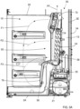
- a refrigeration appliance in the form of a domestic refrigerator is shown, indicated generally as 1.
- the refrigeration appliance can be embodied by refrigeration appliances other than a domestic refrigerator.
- the embodiment described in detail below refers to a bottom mount refrigerator, i.e. of the type including a freezer compartment disposed vertically below a fresh food compartment.
- the refrigerator according to the invention can have any desired configuration, for example a top mount refrigerator wherein the freezer compartment is disposed vertically above the fresh food compartment or a refrigerator comprising only a fresh food compartment or only a freezer compartment.
- the refrigeration appliance 1 illustrated in the figures, hereinafter indicated as refrigerator 1, comprises an outer cabinet 2 and an inner liner 22, internally received in the outer cabinet 2.
- the outer cabinet 2 and the inner liner 22 are separated by a spacing filled with thermal insulation 13, preferably a foam insulation.
- the outer cabinet 2 preferably extends in a vertical direction V and preferably comprises a base 2A suitable to lay on the ground, a roof 2B and lateral side walls 2C, 2D, 2E connecting the base 2A and the roof 2B, preferably two lateral side walls 2C, 2D and a rear side wall 2E.
- lateral side walls 2C, 2D and the rear side wall 2E are preferably aligned to the vertical direction V.
- the refrigerator 1 preferably represents a bottom mount type refrigerator.
- a divider portion 5 ( Figure 3 ) is provided which divides inner liner 22 into a lower space that is used as a freezer compartment 10, and an upper space that is used as a fresh food compartment 12.
- the freezer compartment 10 substantially preferably has the form of a cuboid defining a rectangularly shaped front opening 14.
- a door 15 is preferably pivotally mounted to the outer cabinet 2 and is movable between an open position and a closed position to cover the front opening 14.
- the freezer compartment 10 preferably shows a rear wall 24 which is defined by a portion of the inner liner 22, more preferably a vertical rear wall 24.
- the fresh compartment 12 substantially and preferably has the form of a cuboid defining a rectangularly shaped front opening 16.
- a door 17 is preferably pivotally mounted to the outer cabinet 2 and is movable between an open position and a closed position to cover the front opening 16.
- a single door can be provided to open and close both the front openings 14, 16 of the freezer and the fresh compartments 10, 12.
- the compartments 10, 12 preferably comprise shelves S and/or drawers D for receiving food items.
- a refrigeration system 30 is preferably provided to cool the compartments 10, 12.
- the refrigeration system 30 is apt to cool down air which is circulated inside at least one compartment of refrigerator 1, preferably to cool down air which is circulated inside both compartments 10, 12.
- the refrigeration system 30 preferably comprises a closed recirculating system filled with a suitable refrigerant, for example R12 or R134a.
- the refrigeration system preferably comprises an electric motor-driven compressor 32, a condenser heat exchanger 34, a pressure device such as a capillary tube or a thermostatic valve (not shown) and an evaporator 38.
- a collecting tray 55 is preferably arranged below the evaporator 38 to collect water formed by condensation on the evaporator 38.
- the evaporator 38 is preferably mounted inside the freezer compartment 10, whereas the compressor 32 is mounted external to the freezer compartment 10 and preferably arranged in a working chamber 21 at the bottom of the refrigerator 1.
- the condenser heat exchanger can be a condenser tubing 34 that preferably has a serpentine configuration and is preferably externally secured to the rear side wall 2E of the outer cabinet 2 so as to form what is commonly known as a "hot wall".
- the evaporator 38 is more preferably mounted to the rear wall 24 of the freezer compartment 10 towards the interior of the freezer compartment 10.
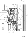
- a pre-assembled fan assembly 50 is arranged closed to the evaporator 38.
- the fan assembly 50 is shown isolated from the rest in figures 4 to 6 .
- the fan assembly 50 is advantageously pre-assembled during manufacturing of the refrigerator 1 and then it is mounted inside the freezer compartment 10 over the evaporator 38.
- the fan assembly 50 is preferably connected to the rear wall 24 of the freezer compartment 10 through connecting means 60.
- the connecting means 60 preferably comprise two lower protruding tabs 61A, 61B with holes for receiving fixing screws (not shown).
- the fan assembly 50 is assembled to the freezer compartment 10 by inserting its upper part in position inside the freezer compartment 10, rotating its lower part to bring the fan assembly 50 in its final position and finally fixing the fan assembly 50 to the inner liner 22 with screws inserted in the tabs 61A, 61B.
- the connecting means may comprise other type of fasteners, such as mechanical (e.g. rivets, nuts and bolts, etc.), chemical (e.g. adhesive, epoxy, etc.), or other type of fasteners.
- the function of the fan assembly 50 is to generate the cooling air stream that is conveyed and recirculated inside the freezer compartment 10 and, in the preferred embodiment here illustrated, also inside the fresh food compartment 12.
- the fan assembly 50 is preferably configured to draw air from the evaporator 38 and to expel it into the freezer compartment 10 and into the fresh food compartment 12.
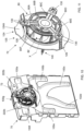
- the fan assembly 50 preferably comprises a first layer 70 of expanded polystyrene, a fan 72, a second layer 74 of expanded polystyrene and a cover plate 76.
- the first layer 70, the fan 72, the second layer 74 and the cover plate 76 are preferably arranged side by side, i.e. arranged one laterally of the other and preferably in a lateral order perpendicular to the vertical direction V.
- each component 70, 72, 74, 76 is at least partially stacked/in contact to the laterally adjacent component.
- expanded polystyrene used for the layers 70, 74 i.e. EPS
- EPS is a lightweight, rigid plastic foam insulation material made of solid polystyrene particles.
- EPS enhances thermal isolation of the fan assembly 50, being EPS a high-quality thermal insulator material.
- EPS enhances acoustic isolation of the fan assembly 50, in particular of noise caused by rotation of the fan 72 and of the air expelled from it.
- using of EPS simplifies the fan assembly 50 construction as EPS is an easily handled material. Still advantageously, EPS is a cheap material.
- the second layer of expanded polystyrene may be omitted.
- the fan 72 preferably comprises a rotor 82 with a rotation axis X.
- the rotor 82 is preferably mounted on a supporting frame 80.
- the supporting frame 80 preferably has a spider shaped structure with arms 80A-80F supporting the rotor 52, as visible in Figure 11 .
- the fan 72 preferably comprises a centrifugal fan, preferably a radial fan.
- the air flows from a suction side 72A of the fan 72 facing the evaporator 38, and the air is then displaced radially, changing its direction (typically by 90°).
- the rotor 82 preferably consists of a rotating arrangement of vanes or blades, rotating around said axis X, which act on the air.
- a fan mouth 122 is arranged at the suction side 72A of the fan 72 to convey the air from the evaporator 38 to the rotor 82.
- the fan mouth 122 preferably faces the evaporator 38 and is preferably placed between the first layer 70 and the fan 72.
- the fan mouth may be omitted.
- a suction chamber 68 is created between the fan 72, preferably the fan mouth 122, and the outlet side 38A of the evaporator 38, as shown in Figure 3B .
- the fan 72 draws air from the evaporator 38 through the suction chamber 68 and expels it outside the fan assembly 50, towards the freezer compartment 10 and the fresh food compartment 12, as better described later.
- the air preferably flows in the compartments 10, 12 to define closed loop circuits and the fan 72 is switched on/off according to operational condition, for example the temperature level inside the compartments 10, 12 and/or opening of the doors, etc.
- the rotating axis X of the rotor 82 is inclined with respect to a vertical direction V.
- the rotating axis X is inclined with respect to the rear side wall 2E of the outer cabinet 2.
- the rotating axis X is preferably inclined with respect to the vertical direction V of an angle W comprised between 10° and 80°, more preferably inclined of an angle W equal to 60°.
- the suction chamber 68 is shaped to guarantee a good fluid dynamics efficiency and at the same time the space occupied by the fan 72 is minimized so that the volume of the freezer compartment 10 is not negatively affected.
- the fan assembly 50 comprises a fastening device 90 apt to fasten the cover plate 76 to the first layer 70 to keep elements of the fan assembly 50 in the assembled configuration.
- the fastening device 90 is apt to fasten the cover plate 76 to the first layer 70 to keep staked, preferably in the following order, the first layer 70, the fan 72 and the second layer 74 in their assembled position.
- the fastening device 90 keeps the elements of the fan assembly 50 firmly together.
- the fan 72 is firmly sandwiched between the layers 70, 74 of expanded polystyrene EPS.
- the fastening device is apt to fasten the cover plate to the first layer to keep staked, preferably in the following order, the first layer and the fan in their assembled position.
- the fastening device 90 comprises snap fit elements.
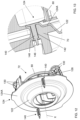
- the fastening device 90 comprises elastic tongues 92 protruding from the cover plate 76 which interact with respective recesses 94 in the first layer 70, as better illustrated in Figure 7 .
- Tongues 92 are preferably made in one piece with the cover plate 76 to realize a single body.
- the fan assembly 50 with associated fastening device 90 guarantees a compact configuration that avoids/reduces vibrations between them, in particular during activation of the fan.
- the fastening device and the cover plate realize a single body so that there is no need of separated fastening means, thus reducing complexity of the fan assembly and simplifying assembling process steps.
- the first layer 70 comprises one or more air conveying channels 100a-100g for conveying cooled air expelled from the fan 72 towards the compartments 10, 12.
- Conveying channels 100a-100g are opened in the direction of the cover plate 76.
- the cover plate 76 opportunely closes the conveying channels 100a-100g allowing the air conveyance.
- the first layer 70 with open channels 100a-100g are easily obtained through an injection mould process with EPS.
- air conveying channels may be realized as closed air conveying channels directly on the first layer.
- air conveying channels 100a-100f that are radially arranged around the fan 72 for the air to the freezer compartment 10 and an upper air conveying channel 100g for the air to the fresh food compartment 12.
- the cover plate 76 preferably comprises one or more air opening 102a-102f communicating with the air conveying channels 100a-100f of the first layer 70. Cooled air advantageously enters the freezer compartment 10 through said air openings 102a-102f, which preferably are grated openings.
- cover plate 76 is made from plastic to provide an aesthetically pleasing appearance to a user.
- an intermediate sheet 105 is interposed between the firs layer 70 and the cover plate 76.
- the intermediate sheet 105 preferably comprises holes 106a-106f aligned with the air openings 102a-102f of the cover plate 76.
- the intermediate sheet 105 enhances the closure of the conveying channels 100a-100g of the first layer 70.
- the intermediate sheet 105 improves the sealing effect for the conveying channels 100a-100g, in particular in case the cover plate 76 is not perfectly planar.
- the intermediate sheet may be omitted.
- the first layer 70 comprises a seat 120 apt to at least partially receive the fan 72.
- a mounting element 124 is preferably used to mount the fan 72 to the first layer 70, preferably to the seat 120. More preferably, the mounting element 124 is preferably used to mount the frame 80 of the fan 72 to the first layer 70.
- the mounting element 124 is integrally made with the fan mouth 122. Manufacturing time and/cost are advantageously reduced.
- the mounting element and fan mouth can be two independent elements.
- the mounting element 124 is arranged in the seat 120 of the first layer 70 and connected thereto.
- the mounting element 124 preferably comprises an annular surface 124A that preferably lays in a plane perpendicular to the axis X of the rotor 82.
- the mounting element 124 preferably comprises one more pins 140 apt to be inserted in respective one or more through holes 142 of the first layer 70.
- the pins 140 preferably protrude from the annular surface 124A of the mounting element 124.
- the pins 140 are axially blocked to the first layer 70 with blocking elements 146, for example internal tooth lock washers, connected at the tip of the pins 140 and abutting a surface 148 of the first layer 70, as better visible in figure 13 .
- the pins 140 allow the constraint of the mounting element 124 to the first layer 70.
- the frame 80 of the fan 72 is connected to the mounting element 124 through a carrier structure 125 preferably comprising ribs 126 protruding from the annular surface 124A of the mounting element 124.
- the ribs 126 define connecting points for the frame 80 of the fan 72, preferably three connecting points ( Figure 11 ).
- vibration dampening elements 130 are interposed between the fan 72 and the mounting element 124.
- the vibration dampening elements 130 are interposed between the frame 80 of the fan 72 and the mounting element 124. More preferably the vibration dampening elements 130 are interposed between the frame 80 of the fan 72 and the carrier structure 125 of the mounting element 124.
- Vibration dampening elements 130 preferably comprise rubber washers interposed between three arms 80A, 80C, 80E of the supporting frame 80 and corresponding ribs 126 of the mounting structure 125.
- Vibration dampening elements 130 advantageously absorb vibrations created by the fan rotation.
- the second layer 74 comprises a seat/opening 220 apt to at least partially receive the fan 72.
- the second layer 74 preferably comprises protruding pins 222a apt to be received in respective holes 222b of the first layer 70 when the fan assembly 50 is assembled.
- the second layer 74 of EPS enhances acoustic isolation of the noise caused by rotation of the fan 72 towards the internal volume of the freezer compartment 10.
- the air preferably flows in the compartments 10, 12 to define closed loop circuits.
- the fan assembly 50 create an air flow paths inside the fresh food compartment 12 and air flow paths in the freezer compartment 10, schematically indicated with FF, F1, F2, F3 in Figures 3 and 3A .
- air flow path FF is generated by the fan assembly 50 and conveyed to the fresh food compartment 12 through the upper air conveying channel 100g of the first layer 70.
- Air flow paths F1, F2, F3 are generated by the fan assembly 50 and conveyed to the freezer compartment 10 through the six air conveying channels 100a-100f of the first layer 70 and air openings 102a-102f of the cover plate 76.
- Main phases for manufacturing the refrigerator 1 according to the invention preferably comprises the following steps:
- Main phases for assembling the fan assembly 50 comprises the following steps:
- noise and vibrations are reduced compared to known appliances since the fan is firmly sandwiched between the layers of expanded polystyrene.
Landscapes
- Engineering & Computer Science (AREA)
- Chemical & Material Sciences (AREA)
- Combustion & Propulsion (AREA)
- Physics & Mathematics (AREA)
- Mechanical Engineering (AREA)
- Thermal Sciences (AREA)
- General Engineering & Computer Science (AREA)
- Cold Air Circulating Systems And Constructional Details In Refrigerators (AREA)
- Removal Of Water From Condensation And Defrosting (AREA)
- Devices That Are Associated With Refrigeration Equipment (AREA)
Claims (14)
- Kühlgerät (1), umfassend:- einen Außenschrank (2), der sich in vertikaler Richtung (V) erstreckt und einen Sockel (2A), der zum Aufstellen auf den Boden geeignet ist, ein Dach (2B) und seitliche Seitenwände (2C, 2D, 2E) umfasst, die den Sockel (2A) und das Dach (2B) verbinden;- eine Innenauskleidung (22), die sich im Inneren des Außenschranks (2) befindet und mindestens ein Fach (10) zum Empfangen von Lebensmitteln definiert;- eine Tür (15, 17), die geeignet ist, das mindestens eine Fach (10) zu öffnen und zu schließen;- ein Kühlsystem (30), das einen Verdampfer (38) zum Abkühlen von Luft für das mindestens eine Fach (10) umfasst, wobei der Verdampfer (38) innerhalb des mindestens einen Fachs (10) an einer ersten Wand (24) desselben angeordnet ist;- eine Gebläseanordnung (50), die innerhalb des Fachs (10) angeordnet und dem Verdampfer (38) zugeordnet ist, um einen Kühlluftstrom für das mindestens eine Fach (10) zu erzeugen;wobei die Gebläseanordnung (50) nebeneinander angeordnet Folgendes umfasst:- eine erste Schicht (70) aus expandiertem Polystyrol;- ein Gebläse (72) umfassend einen Rotor (82) mit einer Drehachse (X), die in Bezug auf eine vertikale Richtung (V) geneigt ist;- eine Abdeckplatte (76);und wobei die Gebläseanordnung (50) eine Befestigungsvorrichtung (90) umfasst, die geeignet ist, die Abdeckplatte (76) an der ersten Schicht (70) zu befestigen, um die Gebläseanordnung (50) in der zusammengebauten Konfiguration zu halten,dadurch gekennzeichnet, dass die Gebläseanordnung (50) ferner eine zweite Schicht (74) aus expandiertem Polystyrol zwischen dem Gebläse (72) und der Abdeckplatte (76) umfasst.
- Gerät (1) gemäß einem der vorhergehenden Ansprüche, dadurch gekennzeichnet, dass die erste Schicht (70) einen oder mehrere Luftförderkanäle (100a-100g) umfasst und die Abdeckplatte (76) eine oder mehrere Luftöffnungen (102a-102g) umfasst, die mit dem einen oder den mehreren Luftförderkanälen (100a-100g) in Verbindung stehen, wenn die Gebläseanordnung (50) zusammengebaut ist.
- Gerät (1) gemäß einem der vorhergehenden Ansprüche, dadurch gekennzeichnet, dass die Befestigungsvorrichtung (90) Schnappverbindungselemente (92) umfasst.
- Gerät (1) gemäß einem der vorhergehenden Ansprüche, dadurch gekennzeichnet, dass die Befestigungsvorrichtung (90) elastische Zungen (92) umfasst, die von der Abdeckplatte (76) hervorstehen und mit Aussparungen (94) in der ersten Schicht (70) zusammenwirken.
- Gerät (1) gemäß einem der vorhergehenden Ansprüche, dadurch gekennzeichnet, dass die erste Schicht (70) einen Sitz (120) umfasst, um mindestens teilweise das Gebläse (72) aufzunehmen.
- Gerät (1) gemäß einem der vorhergehenden Ansprüche, dadurch gekennzeichnet, dass die Gebläseanordnung (50) ein Befestigungselement (124) umfasst, das dazu geeignet ist, das Gebläse (72) an der ersten Schicht (70) zu befestigen.
- Gerät (1) gemäß Anspruch 6, dadurch gekennzeichnet, dass das Befestigungselement (124) einen oder mehrere Stifte (140) umfasst, die dazu geeignet sind, in ein oder mehrere jeweilige Durchgangslöcher (142) der ersten Schicht (70) eingeführt zu werden, und die Sperrelemente (146) umfassen, die mit der Spitze des einen oder der mehreren Stifte verbunden sind und an einer Fläche (148) der ersten Schicht (70) anliegen, wodurch die Fixierung des Befestigungselements (124) an der ersten Schicht (70) ermöglicht wird.
- Gerät (1) gemäß Anspruch 6 oder 7, dadurch gekennzeichnet, dass es ferner vibrationsdämpfende Elemente (130) umfasst, die zwischen dem Gebläse (72) und dem Befestigungselement (124) angeordnet sind.
- Gerät (1) gemäß einem der vorhergehenden Ansprüche, dadurch gekennzeichnet, dass das Gebläse (72) einen Rahmen (80) umfasst, der dazu geeignet ist, den Rotor (82) zu tragen.
- Gerät (1) gemäß Anspruch 9 in Abhängigkeit von einem der Ansprüche 6 bis 8, dadurch gekennzeichnet, dass der Rahmen (80) mit dem Befestigungselement (124) über eine Trägerstruktur (125) verbunden ist.
- Gerät (1) gemäß einem der vorhergehenden Ansprüche, dadurch gekennzeichnet, dass die Gebläseanordnung (50) ferner eine Gebläsemündung (122) umfasst, aus der Luft vom Verdampfer (38) zum Gebläse (72) strömt.
- Gerät (1) gemäß Anspruch 11 in Abhängigkeit von Anspruch 6, dadurch gekennzeichnet, dass die Gebläsemündung (122) und das Befestigungselement (124) einstückig ausgebildet sind.
- Gerät (1) gemäß einem der vorhergehenden Ansprüche, dadurch gekennzeichnet, dass es ferner ein Verbindungsmittel (60, 61A, 61B) umfasst, das dazu geeignet ist, die Gebläseanordnung (50) mit der ersten Wand (24) des Fachs (10) zu verbinden.
- Verfahren zum Herstellen eines Kühlgeräts (1), das die folgenden Schritte umfasst:- Bereitstellen eines Außenschranks (2);- Montieren einer Innenauskleidung (22), um ein Fach (10) zum Empfangen von Lebensmitteln zu definieren;- Montieren eines Kühlsystems (30), das einen Verdampfer (38) umfasst, wobei der Verdampfer (38) innerhalb des Fachs (10) an einer ersten Wand (24) davon angeordnet ist;- Montieren einer Gebläseanordnung (50) angrenzend an den Verdampfer (38), wobei die Gebläseanordnung (50) eine vormontierte Anordnung ist, die durch die Schritte des Befestigens der folgenden Elemente nebeneinander und miteinander erhalten wird:- einer ersten Schicht (70) aus expandiertem Polystyrol;- eines Gebläses (72) umfassend einen Rotor (82) mit einer Drehachse (X), die in Bezug auf eine vertikale Richtung (V) geneigt ist;- einer zweiten Schicht (74) aus expandiertem Polystyrol;- einer Abdeckplatte (76).
Applications Claiming Priority (2)
| Application Number | Priority Date | Filing Date | Title |
|---|---|---|---|
| EP20165291.4A EP3885680B1 (de) | 2020-03-24 | 2020-03-24 | Mit einer gebläseanordnung ausgestattetes kühlgerät und verfahren zur herstellung des besagten geräts |
| PCT/EP2021/055002 WO2021190864A1 (en) | 2020-03-24 | 2021-03-01 | A refrigeration appliance equipped with a fan assembly and a method for manufacturing said appliance |
Publications (2)
| Publication Number | Publication Date |
|---|---|
| EP4127579A1 EP4127579A1 (de) | 2023-02-08 |
| EP4127579B1 true EP4127579B1 (de) | 2025-01-15 |
Family
ID=69960445
Family Applications (2)
| Application Number | Title | Priority Date | Filing Date |
|---|---|---|---|
| EP20165291.4A Active EP3885680B1 (de) | 2020-03-24 | 2020-03-24 | Mit einer gebläseanordnung ausgestattetes kühlgerät und verfahren zur herstellung des besagten geräts |
| EP21707725.4A Active EP4127579B1 (de) | 2020-03-24 | 2021-03-01 | Kühlgerät mit einem gebläsesystem und verfahren zu dessen herstellung |
Family Applications Before (1)
| Application Number | Title | Priority Date | Filing Date |
|---|---|---|---|
| EP20165291.4A Active EP3885680B1 (de) | 2020-03-24 | 2020-03-24 | Mit einer gebläseanordnung ausgestattetes kühlgerät und verfahren zur herstellung des besagten geräts |
Country Status (8)
| Country | Link |
|---|---|
| US (1) | US12442582B2 (de) |
| EP (2) | EP3885680B1 (de) |
| KR (1) | KR20220162714A (de) |
| CN (1) | CN115298493A (de) |
| AU (1) | AU2021244891A1 (de) |
| BR (1) | BR112022018823A2 (de) |
| PL (1) | PL3885680T3 (de) |
| WO (1) | WO2021190864A1 (de) |
Families Citing this family (1)
| Publication number | Priority date | Publication date | Assignee | Title |
|---|---|---|---|---|
| CN114076464B (zh) * | 2020-08-18 | 2023-04-18 | 青岛海尔电冰箱有限公司 | 风冷冰箱 |
Family Cites Families (25)
| Publication number | Priority date | Publication date | Assignee | Title |
|---|---|---|---|---|
| KR0153496B1 (ko) * | 1996-06-29 | 1999-01-15 | 배순훈 | 냉장고 |
| KR20010011784A (ko) * | 1999-07-30 | 2001-02-15 | 구자홍 | 냉장고의 냉기공급장치 |
| DE10145140A1 (de) * | 2001-09-13 | 2003-04-03 | Bsh Bosch Siemens Hausgeraete | Gehäuse für ein Kältegerät |
| JP4620663B2 (ja) * | 2003-07-04 | 2011-01-26 | エレクトロラックス ホーム プロダクツ コーポレイション ナームロゼ フェンノートシャップ | キャビネット冷蔵システム |
| RU2345298C1 (ru) * | 2004-10-28 | 2009-01-27 | Шарп Кабусики Кайся | Холодильник |
| US8863537B2 (en) * | 2006-07-13 | 2014-10-21 | Whirlpool Corporation | Single evaporator refrigeration system for multi-compartment refrigerator appliance with isolated air flows |
| TWI411755B (zh) * | 2008-09-12 | 2013-10-11 | 松下電器產業股份有限公司 | refrigerator |
| US9874403B2 (en) * | 2009-02-27 | 2018-01-23 | Electrolux Home Products, Inc. | Evaporator fins in contact with end bracket |
| DE102009003263A1 (de) * | 2009-05-20 | 2010-11-25 | BSH Bosch und Siemens Hausgeräte GmbH | No-Frost-Kältegerät |
| US8820110B2 (en) * | 2010-02-25 | 2014-09-02 | Electrolux Home Products, Inc. | Ice and water system in refrigerator with stirring fan in ice chamber |
| JP4920778B2 (ja) * | 2010-08-17 | 2012-04-18 | シャープ株式会社 | 冷却庫 |
| CN104220826B (zh) * | 2012-01-31 | 2016-08-24 | 伊莱克斯家用产品公司 | 用于制冷设备的制冰机 |
| AU2013392974B2 (en) * | 2013-06-20 | 2016-11-17 | Arcelik Anonim Sirketi | Improved fan assembly for a refrigeration appliance |
| US10101077B2 (en) * | 2014-09-25 | 2018-10-16 | Electrolux Home Products, Inc. | Fan mounting assembly, evaporator coil cover and air tower of refrigerator |
| CN104374140A (zh) * | 2014-10-14 | 2015-02-25 | 合肥华凌股份有限公司 | 风道组件及冰箱 |
| DE102014222851A1 (de) * | 2014-11-10 | 2016-05-12 | BSH Hausgeräte GmbH | No-Frost-Kältegerät |
| US10254037B2 (en) * | 2016-03-24 | 2019-04-09 | Electrolux Home Products, Inc. | Evaporator box fan mounting solution |
| KR101852677B1 (ko) * | 2016-05-26 | 2018-04-26 | 엘지전자 주식회사 | 냉장고 |
| JP2018066346A (ja) | 2016-10-21 | 2018-04-26 | 日本電産株式会社 | 送風装置及びそれを備えた冷蔵庫 |
| US10712079B2 (en) * | 2016-12-01 | 2020-07-14 | Bsh Hausgeraete Gmbh | Cooling device comprising an evaporator cover sheet having a fixing assembly |
| CN106958973A (zh) | 2017-05-25 | 2017-07-18 | 合肥美菱股份有限公司 | 一种小容积的卧式无霜冷柜 |
| CN107356037B (zh) | 2017-06-29 | 2019-12-24 | 青岛海尔股份有限公司 | 冰箱 |
| CN107388702B (zh) | 2017-08-25 | 2019-12-06 | 合肥华凌股份有限公司 | 制冷系统及冰箱 |
| US11346591B2 (en) * | 2018-03-02 | 2022-05-31 | Electrolux Do Brasil S.A. | Single air passageway and damper assembly in a variable climate zone compartment |
| US11559147B2 (en) * | 2019-05-07 | 2023-01-24 | Carrier Corporation | Refrigerated display cabinet utilizing a radial cross flow fan |
-
2020
- 2020-03-24 PL PL20165291.4T patent/PL3885680T3/pl unknown
- 2020-03-24 EP EP20165291.4A patent/EP3885680B1/de active Active
-
2021
- 2021-03-01 CN CN202180023092.3A patent/CN115298493A/zh active Pending
- 2021-03-01 AU AU2021244891A patent/AU2021244891A1/en active Pending
- 2021-03-01 BR BR112022018823A patent/BR112022018823A2/pt unknown
- 2021-03-01 EP EP21707725.4A patent/EP4127579B1/de active Active
- 2021-03-01 WO PCT/EP2021/055002 patent/WO2021190864A1/en not_active Ceased
- 2021-03-01 US US17/908,932 patent/US12442582B2/en active Active
- 2021-03-01 KR KR1020227034371A patent/KR20220162714A/ko active Pending
Also Published As
| Publication number | Publication date |
|---|---|
| BR112022018823A2 (pt) | 2022-11-08 |
| EP3885680A1 (de) | 2021-09-29 |
| US20230098419A1 (en) | 2023-03-30 |
| WO2021190864A1 (en) | 2021-09-30 |
| EP3885680B1 (de) | 2024-03-13 |
| KR20220162714A (ko) | 2022-12-08 |
| AU2021244891A1 (en) | 2022-08-25 |
| PL3885680T3 (pl) | 2024-07-15 |
| CN115298493A (zh) | 2022-11-04 |
| EP4127579A1 (de) | 2023-02-08 |
| US12442582B2 (en) | 2025-10-14 |
Similar Documents
| Publication | Publication Date | Title |
|---|---|---|
| US12104842B2 (en) | Refrigerator having centrifugal fan with volute | |
| US10254037B2 (en) | Evaporator box fan mounting solution | |
| US20040139763A1 (en) | Refrigerator | |
| EP2975341B1 (de) | Kühlschrank | |
| CN109838404B (zh) | 风扇组装体以及包括该风扇组装体的冰箱 | |
| EP4127579B1 (de) | Kühlgerät mit einem gebläsesystem und verfahren zu dessen herstellung | |
| KR20180080082A (ko) | 냉장고 | |
| WO2021190773A1 (en) | A refrigeration appliance equipped with a refrigeration system, preferably a refrigeration system having a fan for circulating air | |
| EP3885678B1 (de) | Kühlgerät mit einem gebläsesystem | |
| CN114729773B (zh) | 可变气候区室 | |
| KR101659907B1 (ko) | 냉장고용 일체형 오거모터 어셈블리 및 그 오거모터 어셈블리의 제조방법 | |
| US6094932A (en) | Refrigerator air flow diffuser assembly | |
| RU2473022C2 (ru) | Холодильный аппарат | |
| CN211552159U (zh) | 冰箱 | |
| KR20090000907U (ko) | 냉장고 | |
| US20180156519A1 (en) | Home Appliance Device | |
| EP3945270A1 (de) | Frostfreies kühlschrankgerät | |
| EP3954904B1 (de) | Lüfteranordnung für elektrogerät und kühlelektrogerät | |
| EP1526348A1 (de) | Einbaukühlschrank | |
| CN118274519A (zh) | 冰箱及其风道组件 | |
| CN118274558A (zh) | 用于冰箱的风道盖板、风道组件及冰箱 | |
| EP4116646A1 (de) | Kältegerät | |
| CN118274520A (zh) | 冰箱及其风道组件 | |
| JP2002081840A (ja) | 冷蔵庫 | |
| CN111426125A (zh) | 一种单系统单风机多温区的冰箱 |
Legal Events
| Date | Code | Title | Description |
|---|---|---|---|
| STAA | Information on the status of an ep patent application or granted ep patent |
Free format text: STATUS: UNKNOWN |
|
| STAA | Information on the status of an ep patent application or granted ep patent |
Free format text: STATUS: THE INTERNATIONAL PUBLICATION HAS BEEN MADE |
|
| PUAI | Public reference made under article 153(3) epc to a published international application that has entered the european phase |
Free format text: ORIGINAL CODE: 0009012 |
|
| STAA | Information on the status of an ep patent application or granted ep patent |
Free format text: STATUS: REQUEST FOR EXAMINATION WAS MADE |
|
| 17P | Request for examination filed |
Effective date: 20221024 |
|
| AK | Designated contracting states |
Kind code of ref document: A1 Designated state(s): AL AT BE BG CH CY CZ DE DK EE ES FI FR GB GR HR HU IE IS IT LI LT LU LV MC MK MT NL NO PL PT RO RS SE SI SK SM TR |
|
| DAV | Request for validation of the european patent (deleted) | ||
| DAX | Request for extension of the european patent (deleted) | ||
| GRAP | Despatch of communication of intention to grant a patent |
Free format text: ORIGINAL CODE: EPIDOSNIGR1 |
|
| STAA | Information on the status of an ep patent application or granted ep patent |
Free format text: STATUS: GRANT OF PATENT IS INTENDED |
|
| INTG | Intention to grant announced |
Effective date: 20241011 |
|
| GRAS | Grant fee paid |
Free format text: ORIGINAL CODE: EPIDOSNIGR3 |
|
| GRAA | (expected) grant |
Free format text: ORIGINAL CODE: 0009210 |
|
| STAA | Information on the status of an ep patent application or granted ep patent |
Free format text: STATUS: THE PATENT HAS BEEN GRANTED |
|
| P01 | Opt-out of the competence of the unified patent court (upc) registered |
Free format text: CASE NUMBER: APP_63932/2024 Effective date: 20241203 |
|
| AK | Designated contracting states |
Kind code of ref document: B1 Designated state(s): AL AT BE BG CH CY CZ DE DK EE ES FI FR GB GR HR HU IE IS IT LI LT LU LV MC MK MT NL NO PL PT RO RS SE SI SK SM TR |
|
| REG | Reference to a national code |
Ref country code: CH Ref legal event code: EP Ref country code: GB Ref legal event code: FG4D |
|
| REG | Reference to a national code |
Ref country code: DE Ref legal event code: R096 Ref document number: 602021024949 Country of ref document: DE |
|
| REG | Reference to a national code |
Ref country code: IE Ref legal event code: FG4D |
|
| PGFP | Annual fee paid to national office [announced via postgrant information from national office to epo] |
Ref country code: DE Payment date: 20250327 Year of fee payment: 5 |
|
| PGFP | Annual fee paid to national office [announced via postgrant information from national office to epo] |
Ref country code: AT Payment date: 20250417 Year of fee payment: 5 |
|
| REG | Reference to a national code |
Ref country code: NL Ref legal event code: MP Effective date: 20250115 |
|
| PG25 | Lapsed in a contracting state [announced via postgrant information from national office to epo] |
Ref country code: NL Free format text: LAPSE BECAUSE OF FAILURE TO SUBMIT A TRANSLATION OF THE DESCRIPTION OR TO PAY THE FEE WITHIN THE PRESCRIBED TIME-LIMIT Effective date: 20250115 |
|
| PG25 | Lapsed in a contracting state [announced via postgrant information from national office to epo] |
Ref country code: RS Free format text: LAPSE BECAUSE OF FAILURE TO SUBMIT A TRANSLATION OF THE DESCRIPTION OR TO PAY THE FEE WITHIN THE PRESCRIBED TIME-LIMIT Effective date: 20250415 |
|
| PG25 | Lapsed in a contracting state [announced via postgrant information from national office to epo] |
Ref country code: FI Free format text: LAPSE BECAUSE OF FAILURE TO SUBMIT A TRANSLATION OF THE DESCRIPTION OR TO PAY THE FEE WITHIN THE PRESCRIBED TIME-LIMIT Effective date: 20250115 |
|
| PG25 | Lapsed in a contracting state [announced via postgrant information from national office to epo] |
Ref country code: PL Free format text: LAPSE BECAUSE OF FAILURE TO SUBMIT A TRANSLATION OF THE DESCRIPTION OR TO PAY THE FEE WITHIN THE PRESCRIBED TIME-LIMIT Effective date: 20250115 |
|
| PG25 | Lapsed in a contracting state [announced via postgrant information from national office to epo] |
Ref country code: ES Free format text: LAPSE BECAUSE OF FAILURE TO SUBMIT A TRANSLATION OF THE DESCRIPTION OR TO PAY THE FEE WITHIN THE PRESCRIBED TIME-LIMIT Effective date: 20250115 |
|
| REG | Reference to a national code |
Ref country code: LT Ref legal event code: MG9D |
|
| PG25 | Lapsed in a contracting state [announced via postgrant information from national office to epo] |
Ref country code: IS Free format text: LAPSE BECAUSE OF FAILURE TO SUBMIT A TRANSLATION OF THE DESCRIPTION OR TO PAY THE FEE WITHIN THE PRESCRIBED TIME-LIMIT Effective date: 20250515 Ref country code: NO Free format text: LAPSE BECAUSE OF FAILURE TO SUBMIT A TRANSLATION OF THE DESCRIPTION OR TO PAY THE FEE WITHIN THE PRESCRIBED TIME-LIMIT Effective date: 20250415 |
|
| PGFP | Annual fee paid to national office [announced via postgrant information from national office to epo] |
Ref country code: IT Payment date: 20250409 Year of fee payment: 5 |
|
| REG | Reference to a national code |
Ref country code: AT Ref legal event code: MK05 Ref document number: 1760082 Country of ref document: AT Kind code of ref document: T Effective date: 20250115 |
|
| PG25 | Lapsed in a contracting state [announced via postgrant information from national office to epo] |
Ref country code: HR Free format text: LAPSE BECAUSE OF FAILURE TO SUBMIT A TRANSLATION OF THE DESCRIPTION OR TO PAY THE FEE WITHIN THE PRESCRIBED TIME-LIMIT Effective date: 20250115 |
|
| PG25 | Lapsed in a contracting state [announced via postgrant information from national office to epo] |
Ref country code: PT Free format text: LAPSE BECAUSE OF FAILURE TO SUBMIT A TRANSLATION OF THE DESCRIPTION OR TO PAY THE FEE WITHIN THE PRESCRIBED TIME-LIMIT Effective date: 20250515 Ref country code: LV Free format text: LAPSE BECAUSE OF FAILURE TO SUBMIT A TRANSLATION OF THE DESCRIPTION OR TO PAY THE FEE WITHIN THE PRESCRIBED TIME-LIMIT Effective date: 20250115 |
|
| PG25 | Lapsed in a contracting state [announced via postgrant information from national office to epo] |
Ref country code: GR Free format text: LAPSE BECAUSE OF FAILURE TO SUBMIT A TRANSLATION OF THE DESCRIPTION OR TO PAY THE FEE WITHIN THE PRESCRIBED TIME-LIMIT Effective date: 20250416 Ref country code: BG Free format text: LAPSE BECAUSE OF FAILURE TO SUBMIT A TRANSLATION OF THE DESCRIPTION OR TO PAY THE FEE WITHIN THE PRESCRIBED TIME-LIMIT Effective date: 20250115 |
|
| PG25 | Lapsed in a contracting state [announced via postgrant information from national office to epo] |
Ref country code: AT Free format text: LAPSE BECAUSE OF FAILURE TO SUBMIT A TRANSLATION OF THE DESCRIPTION OR TO PAY THE FEE WITHIN THE PRESCRIBED TIME-LIMIT Effective date: 20250115 |
|
| PGFP | Annual fee paid to national office [announced via postgrant information from national office to epo] |
Ref country code: TR Payment date: 20250414 Year of fee payment: 5 |
|
| PG25 | Lapsed in a contracting state [announced via postgrant information from national office to epo] |
Ref country code: SE Free format text: LAPSE BECAUSE OF FAILURE TO SUBMIT A TRANSLATION OF THE DESCRIPTION OR TO PAY THE FEE WITHIN THE PRESCRIBED TIME-LIMIT Effective date: 20250115 |
|
| PG25 | Lapsed in a contracting state [announced via postgrant information from national office to epo] |
Ref country code: SM Free format text: LAPSE BECAUSE OF FAILURE TO SUBMIT A TRANSLATION OF THE DESCRIPTION OR TO PAY THE FEE WITHIN THE PRESCRIBED TIME-LIMIT Effective date: 20250115 |
|
| PG25 | Lapsed in a contracting state [announced via postgrant information from national office to epo] |
Ref country code: DK Free format text: LAPSE BECAUSE OF FAILURE TO SUBMIT A TRANSLATION OF THE DESCRIPTION OR TO PAY THE FEE WITHIN THE PRESCRIBED TIME-LIMIT Effective date: 20250115 |
|
| PG25 | Lapsed in a contracting state [announced via postgrant information from national office to epo] |
Ref country code: MC Free format text: LAPSE BECAUSE OF FAILURE TO SUBMIT A TRANSLATION OF THE DESCRIPTION OR TO PAY THE FEE WITHIN THE PRESCRIBED TIME-LIMIT Effective date: 20250115 |
|
| REG | Reference to a national code |
Ref country code: DE Ref legal event code: R097 Ref document number: 602021024949 Country of ref document: DE |
|
| PG25 | Lapsed in a contracting state [announced via postgrant information from national office to epo] |
Ref country code: EE Free format text: LAPSE BECAUSE OF FAILURE TO SUBMIT A TRANSLATION OF THE DESCRIPTION OR TO PAY THE FEE WITHIN THE PRESCRIBED TIME-LIMIT Effective date: 20250115 Ref country code: CZ Free format text: LAPSE BECAUSE OF FAILURE TO SUBMIT A TRANSLATION OF THE DESCRIPTION OR TO PAY THE FEE WITHIN THE PRESCRIBED TIME-LIMIT Effective date: 20250115 |
|
| REG | Reference to a national code |
Ref country code: CH Ref legal event code: H13 Free format text: ST27 STATUS EVENT CODE: U-0-0-H10-H13 (AS PROVIDED BY THE NATIONAL OFFICE) Effective date: 20251023 |
|
| PG25 | Lapsed in a contracting state [announced via postgrant information from national office to epo] |
Ref country code: RO Free format text: LAPSE BECAUSE OF FAILURE TO SUBMIT A TRANSLATION OF THE DESCRIPTION OR TO PAY THE FEE WITHIN THE PRESCRIBED TIME-LIMIT Effective date: 20250115 |
|
| PG25 | Lapsed in a contracting state [announced via postgrant information from national office to epo] |
Ref country code: SK Free format text: LAPSE BECAUSE OF FAILURE TO SUBMIT A TRANSLATION OF THE DESCRIPTION OR TO PAY THE FEE WITHIN THE PRESCRIBED TIME-LIMIT Effective date: 20250115 |
|
| PG25 | Lapsed in a contracting state [announced via postgrant information from national office to epo] |
Ref country code: LU Free format text: LAPSE BECAUSE OF NON-PAYMENT OF DUE FEES Effective date: 20250301 |
|
| PLBE | No opposition filed within time limit |
Free format text: ORIGINAL CODE: 0009261 |
|
| STAA | Information on the status of an ep patent application or granted ep patent |
Free format text: STATUS: NO OPPOSITION FILED WITHIN TIME LIMIT |
|
| REG | Reference to a national code |
Ref country code: BE Ref legal event code: MM Effective date: 20250331 |
|
| 26N | No opposition filed |
Effective date: 20251016 |