EP4127481B1 - Wärmetauscheranordnung - Google Patents
Wärmetauscheranordnung Download PDFInfo
- Publication number
- EP4127481B1 EP4127481B1 EP21716107.4A EP21716107A EP4127481B1 EP 4127481 B1 EP4127481 B1 EP 4127481B1 EP 21716107 A EP21716107 A EP 21716107A EP 4127481 B1 EP4127481 B1 EP 4127481B1
- Authority
- EP
- European Patent Office
- Prior art keywords
- heat exchanger
- radial fan
- air
- housing
- arrangement
- Prior art date
- Legal status (The legal status is an assumption and is not a legal conclusion. Google has not performed a legal analysis and makes no representation as to the accuracy of the status listed.)
- Active
Links
Images


Classifications
-
- F—MECHANICAL ENGINEERING; LIGHTING; HEATING; WEAPONS; BLASTING
- F04—POSITIVE - DISPLACEMENT MACHINES FOR LIQUIDS; PUMPS FOR LIQUIDS OR ELASTIC FLUIDS
- F04D—NON-POSITIVE-DISPLACEMENT PUMPS
- F04D17/00—Radial-flow pumps, e.g. centrifugal pumps; Helico-centrifugal pumps
- F04D17/02—Radial-flow pumps, e.g. centrifugal pumps; Helico-centrifugal pumps having non-centrifugal stages, e.g. centripetal
-
- F—MECHANICAL ENGINEERING; LIGHTING; HEATING; WEAPONS; BLASTING
- F04—POSITIVE - DISPLACEMENT MACHINES FOR LIQUIDS; PUMPS FOR LIQUIDS OR ELASTIC FLUIDS
- F04D—NON-POSITIVE-DISPLACEMENT PUMPS
- F04D29/00—Details, component parts, or accessories
- F04D29/26—Rotors specially for elastic fluids
- F04D29/28—Rotors specially for elastic fluids for centrifugal or helico-centrifugal pumps for radial-flow or helico-centrifugal pumps
- F04D29/284—Rotors specially for elastic fluids for centrifugal or helico-centrifugal pumps for radial-flow or helico-centrifugal pumps for compressors
-
- F—MECHANICAL ENGINEERING; LIGHTING; HEATING; WEAPONS; BLASTING
- F04—POSITIVE - DISPLACEMENT MACHINES FOR LIQUIDS; PUMPS FOR LIQUIDS OR ELASTIC FLUIDS
- F04D—NON-POSITIVE-DISPLACEMENT PUMPS
- F04D29/00—Details, component parts, or accessories
- F04D29/40—Casings; Connections of working fluid
- F04D29/42—Casings; Connections of working fluid for radial or helico-centrifugal pumps
- F04D29/4206—Casings; Connections of working fluid for radial or helico-centrifugal pumps especially adapted for elastic fluid pumps
- F04D29/4226—Fan casings
-
- F—MECHANICAL ENGINEERING; LIGHTING; HEATING; WEAPONS; BLASTING
- F04—POSITIVE - DISPLACEMENT MACHINES FOR LIQUIDS; PUMPS FOR LIQUIDS OR ELASTIC FLUIDS
- F04D—NON-POSITIVE-DISPLACEMENT PUMPS
- F04D29/00—Details, component parts, or accessories
- F04D29/58—Cooling; Heating; Diminishing heat transfer
- F04D29/582—Cooling; Heating; Diminishing heat transfer specially adapted for elastic fluid pumps
-
- F—MECHANICAL ENGINEERING; LIGHTING; HEATING; WEAPONS; BLASTING
- F24—HEATING; RANGES; VENTILATING
- F24F—AIR-CONDITIONING; AIR-HUMIDIFICATION; VENTILATION; USE OF AIR CURRENTS FOR SCREENING
- F24F1/00—Room units for air-conditioning, e.g. separate or self-contained units or units receiving primary air from a central station
- F24F1/0007—Indoor units, e.g. fan coil units
- F24F1/0018—Indoor units, e.g. fan coil units characterised by fans
- F24F1/0022—Centrifugal or radial fans
-
- F—MECHANICAL ENGINEERING; LIGHTING; HEATING; WEAPONS; BLASTING
- F24—HEATING; RANGES; VENTILATING
- F24F—AIR-CONDITIONING; AIR-HUMIDIFICATION; VENTILATION; USE OF AIR CURRENTS FOR SCREENING
- F24F12/00—Use of energy recovery systems in air conditioning, ventilation or screening
- F24F12/001—Use of energy recovery systems in air conditioning, ventilation or screening with heat-exchange between supplied and exhausted air
- F24F12/002—Use of energy recovery systems in air conditioning, ventilation or screening with heat-exchange between supplied and exhausted air using an intermediate heat-transfer fluid
- F24F12/003—Use of energy recovery systems in air conditioning, ventilation or screening with heat-exchange between supplied and exhausted air using an intermediate heat-transfer fluid using a heat pump
-
- F—MECHANICAL ENGINEERING; LIGHTING; HEATING; WEAPONS; BLASTING
- F24—HEATING; RANGES; VENTILATING
- F24V—COLLECTION, PRODUCTION OR USE OF HEAT NOT OTHERWISE PROVIDED FOR
- F24V50/00—Use of heat from natural sources, e.g. from the sea
-
- F—MECHANICAL ENGINEERING; LIGHTING; HEATING; WEAPONS; BLASTING
- F28—HEAT EXCHANGE IN GENERAL
- F28D—HEAT-EXCHANGE APPARATUS, NOT PROVIDED FOR IN ANOTHER SUBCLASS, IN WHICH THE HEAT-EXCHANGE MEDIA DO NOT COME INTO DIRECT CONTACT
- F28D1/00—Heat-exchange apparatus having stationary conduit assemblies for one heat-exchange medium only, the media being in contact with different sides of the conduit wall, in which the other heat-exchange medium is a large body of fluid, e.g. domestic or motor car radiators
- F28D1/02—Heat-exchange apparatus having stationary conduit assemblies for one heat-exchange medium only, the media being in contact with different sides of the conduit wall, in which the other heat-exchange medium is a large body of fluid, e.g. domestic or motor car radiators with heat-exchange conduits immersed in the body of fluid
- F28D1/0233—Heat-exchange apparatus having stationary conduit assemblies for one heat-exchange medium only, the media being in contact with different sides of the conduit wall, in which the other heat-exchange medium is a large body of fluid, e.g. domestic or motor car radiators with heat-exchange conduits immersed in the body of fluid with air flow channels
- F28D1/024—Heat-exchange apparatus having stationary conduit assemblies for one heat-exchange medium only, the media being in contact with different sides of the conduit wall, in which the other heat-exchange medium is a large body of fluid, e.g. domestic or motor car radiators with heat-exchange conduits immersed in the body of fluid with air flow channels with an air driving element
-
- Y—GENERAL TAGGING OF NEW TECHNOLOGICAL DEVELOPMENTS; GENERAL TAGGING OF CROSS-SECTIONAL TECHNOLOGIES SPANNING OVER SEVERAL SECTIONS OF THE IPC; TECHNICAL SUBJECTS COVERED BY FORMER USPC CROSS-REFERENCE ART COLLECTIONS [XRACs] AND DIGESTS
- Y02—TECHNOLOGIES OR APPLICATIONS FOR MITIGATION OR ADAPTATION AGAINST CLIMATE CHANGE
- Y02B—CLIMATE CHANGE MITIGATION TECHNOLOGIES RELATED TO BUILDINGS, e.g. HOUSING, HOUSE APPLIANCES OR RELATED END-USER APPLICATIONS
- Y02B30/00—Energy efficient heating, ventilation or air conditioning [HVAC]
- Y02B30/52—Heat recovery pumps, i.e. heat pump based systems or units able to transfer the thermal energy from one area of the premises or part of the facilities to a different one, improving the overall efficiency
-
- Y—GENERAL TAGGING OF NEW TECHNOLOGICAL DEVELOPMENTS; GENERAL TAGGING OF CROSS-SECTIONAL TECHNOLOGIES SPANNING OVER SEVERAL SECTIONS OF THE IPC; TECHNICAL SUBJECTS COVERED BY FORMER USPC CROSS-REFERENCE ART COLLECTIONS [XRACs] AND DIGESTS
- Y02—TECHNOLOGIES OR APPLICATIONS FOR MITIGATION OR ADAPTATION AGAINST CLIMATE CHANGE
- Y02B—CLIMATE CHANGE MITIGATION TECHNOLOGIES RELATED TO BUILDINGS, e.g. HOUSING, HOUSE APPLIANCES OR RELATED END-USER APPLICATIONS
- Y02B30/00—Energy efficient heating, ventilation or air conditioning [HVAC]
- Y02B30/56—Heat recovery units
Definitions
- the invention relates to a heat exchanger arrangement.
- A1 is a storage facility for providing the input heat energy at a low temperature level for heat pump systems, which absorb this energy and release it again at a higher temperature level.
- a water basin is designed in such a way that its water content can freeze without damaging the basin and that a heat exchanger system located on the bottom of the basin or embedded in the bottom of the basin allows the cooling and freezing heat of this basin to be fed to the cold side of a heat pump.
- an energy storage device which has a heat exchanger which is arranged floating on a lower basin which is preferably filled with water via a first supply line and is designed as a lake wherein water from the lower basin can be supplied via a second supply line and coolant penetrating the heat exchanger can be supplied to a heat pump in separate circuits via a third supply line, so that energy can be extracted from the water of the lower basin via the heat exchanger by freezing the water in the lower basin or in the form of sensible heat and can be passed on to a consumer for heat release and/or cold release.
- the DE 10 2015 121 177 A1 a floating device for introducing thermal energy into a body of water and for extracting thermal energy from the body of water is known, which device has a water heat exchanger which, after the device has been inserted into the body of water, is immersed in the body of water and has an inlet and an outlet for a heat transfer fluid which can release thermal energy to the body of water or extract thermal energy from the body of water.
- the device also has an air heat exchanger which can be penetrated by ambient air and which also has an inlet for water originating from the body of water with a corresponding outlet so that water from the body of water can flow through the air heat exchanger, whereby thermal energy can be transferred between the ambient air flowing through the air heat exchanger and the water flowing through the air heat exchanger.
- the devices described above usually work together with a heat pump installed in a building. This can be supplied with electrical energy via the power grid or its own power storage unit, for example.
- a heat exchanger arrangement is known in which a radial fan is arranged for forward operation above a heat exchanger, so that the supply air passes through the heat exchanger to the radial fan's suction side and then transported via the pressure side to an exhaust air opening.
- a device for heat recovery which comprises a heat exchanger which is arranged in a housing sunk into the ground, which has an air inlet and an air outlet, between which an air flow generated by a fan flows.
- the heat exchanger is arranged in the underground housing in order to avoid disturbing noise emissions.
- the underground housing is arranged within an earth excavation which is filled with a drainage material such as gravel.
- the JP S55 155125 A shows a thin air conditioner in which a blowing centripetal fan is provided opposite an air outlet opening and a heat exchanger is arranged around it.
- the JP H09 303853 A shows the arrangement of a rectification heat exchanger at an air flow passage located between a cross-flow fan and an indoor heat exchanger.
- a heat exchanger arrangement comprising a housing in which at least one supply air opening is arranged on the circumference, a cover which covers the housing on an upper side and in which at least one exhaust air opening is arranged, wherein a backwards-operating radial fan is arranged within the housing in such a way that it can generate an air flow between the supply air opening and the exhaust air opening which is directed radially inwards with respect to its axis of rotation and which flows through at least one air heat exchanger arranged in the housing.
- the supply air opening is arranged between the cover and the housing, and the air flow generated by the radial fan flows out through the exhaust air opening in an upward direction.
- a backwards-operating radial fan is suitable for providing the desired ventilation performance with minimal acoustic emissions.
- Radial fans with a radially outward-directed air flow are usually used in forward operation, with the air being sucked in towards the axis of rotation.
- An axial fan is typically used for radial outflow.
- the advantage of the reverse-running radial fan over an axial fan is that it can be operated at a low speed, so that the fan operation produces almost no perceptible acoustic emissions.
- Reverse running means that the suction side of the radial fan lies outside the blades with respect to its axis of rotation, whereas the pressure side lies inside the radial fan with respect to the axis of rotation. An air flow is therefore generated by the radial fan in reverse operation from the outer suction side to the inner pressure side.
- the air heat exchanger is arranged inside a housing, whereby the housing has an external supply air opening and an internal exhaust air opening with respect to a central axis, between which a horizontal air flow is generated by means of the radial fan, which flows through the air heat exchanger or flows past the fins of the air heat exchanger in the usual way.
- the term inside and outside refers to This refers to directions emanating from the axis of rotation of the radial fan, with a component that is closer to the axis of rotation being referred to as being inside.
- the central axis does not have to be the geometric center of the housing; rather, the central axis is a reference point within the housing around which the radial fan is arranged first, then the air heat exchanger further out, and then the supply air opening further out.
- the axis of rotation and the central axis lie on top of one another.
- the exhaust air opening is arranged above the pressure side of the radial fan so that the air flow generated horizontally on the suction side can leave the housing in a vertical direction on the pressure side.
- the heat exchanger arrangement is usually arranged so that the axis of rotation of the radial fan is perpendicular to the floor.
- a radial fan in reverse operation has the advantage that it can be designed with a larger diameter, so that high volumes of air can be moved at low speeds and low air flow velocities.
- the radial fan is advantageously enclosed in the housing in the direction of its axis of rotation up and down.
- the enclosure can also be part of the housing or other components of the heat exchanger arrangement.
- the maximum transportable air flow can be specified accordingly by choosing the dimensions of the radial fan.
- ambient air is sucked into the housing through the supply air openings, then guided radially through the air channels of the fins of the air heat exchanger to the radial fan, then transported by the radial fan to the pressure side and finally discharged axially from the housing through the exhaust air opening.
- the air heat exchanger can either be arranged all the way around the radial fan or comprise individual blocks that are arranged around the radial fan.
- the supply air openings are arranged and dimensioned so that ambient air can flow through the air heat exchanger.
- the radial fan has a plurality of blades which are surrounded by a guide arrangement with a plurality of louvres.
- a baffle arrangement is arranged inside the radial fan, which has slats that direct the air flow on the pressure side of the radial fan towards the axis of rotation of the radial fan and/or towards the exhaust air openings.
- the blades of the radial fan and the slats of the guide vane arrangement are curved in opposite directions.
- the air is diverted along the blades of the radial fan.
- the air flow coming from the radial fan is stripped off the baffle arrangement and directed towards the exhaust air opening or to the center of the baffle arrangement, which ideally coincides with the axis of rotation of the radial fan, so that excess pressure is created there, which escapes through the exhaust air opening.
- the blades of the radial fan are curved forwards in relation to reverse operation and the fins of the baffle arrangement are curved backwards.
- the blades of the radial fan and/or the slats of the guide vane arrangement are formed with a constant curvature along and parallel to their vertical axis.
- Each blade or lamella therefore has a circle center that is offset parallel to its vertical axis, around which the blade is formed with a constant radius and thus with a constant curvature.
- the blades or lamellae could also have a non-constant curvature, in particular such that the curvature decreases towards the axis of rotation.
- the radial fan is therefore advantageously designed to be cylindrical, so that the vertical axes of the blades are arranged parallel to one another and parallel to the axis of rotation, with the axis of rotation simultaneously being aligned essentially parallel to the center axis of the housing.
- the center axis of the housing is normally positioned on the cover of the housing.
- the guide vane arrangement advantageously also has a cylindrical shape, in which the vertical axes of the lamellae are aligned parallel to one another and parallel to the axis of rotation of the radial fan.
- inwardly tapering regions are formed between the slats (LA), so that the air flow experiences an increase in pressure towards the inside.
- the air supply opening is arranged between the cover and the housing.
- the supply air openings are aligned horizontally to the central axis of the housing. This has the advantage that thermal short circuits between the exhaust air and the supply air can be avoided or reduced. In addition, such an arrangement is suitable for use with an energy storage system, as described below.
- the reverse-operated radial fan and the guide vane arrangement overlap at least in sections along the axis of rotation of the radial fan.
- the supply air openings of the air heat exchangers of the radial fans and the after-flow arrangement are located one above the other at least along a common radial beam around the central axis. Air flowing horizontally from the supply air opening to the pressure side of the radial fan thus passes the air heat exchanger, the radial fan and the after-flow arrangement.
- the reverse-operating radial fan is driven by an electric motor.
- the electric motor can be arranged in an insulating layer to absorb as much of the noise emanating from the motor as possible within the housing.
- Such a system for energy storage and heat exchange comprises an aforementioned heat exchanger arrangement, a water tank for storing heat, a water heat exchanger protruding into the water tank and a heat pump which can convey a medium for heat exchange between the air heat exchanger of the heat exchanger arrangement and/or the water heat exchanger so that heat can be exchanged, wherein the water tank can be sunk in a hole in the ground and the heat exchanger arrangement is arranged on the water tank in the direction of the central axis of the housing so that at least the air supply openings protrude above the ground.
- one of the aforementioned heat exchanger arrangements is combined with an energy storage device.
- the energy storage device stores heat within a water reservoir or can release heat from a heat pump into the water reservoir.
- the operation of the water heat exchanger, the heat exchanger arrangement and the heat pump is controlled by a control device.
- the water reservoir and the heat exchanger arrangement can comprise a common housing.
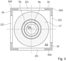
- the heat exchanger arrangement comprises a housing GE with supply air openings ZO and, in relation to the supply air openings ZO, internal exhaust air openings AO, whereby the designation internal and external is used with reference to a central axis MA which sits normally on a cover DE of the housing and penetrates the housing.
- An air heat exchanger LT is arranged inside, starting from the supply air openings ZO.
- a radial fan RL is arranged even further inside, to which a downstream guide arrangement NL is connected inside.
- the radial fan RL is driven by an electric motor MO in reverse operation, so that an air flow LS flows from the supply air openings ZO through the air heat exchanger LT, the radial fan RL and the downstream guide arrangement NL to the exhaust air opening AO.
- the air heat exchanger LT is therefore located on a suction side SS of the radial fan RL, whereas the downstream guide arrangement NL and the exhaust air opening AO are located on the pressure side DS of the radial fan RL.
- the electric motor MO is arranged within an insulation layer IS for acoustic and/or thermal insulation.
- the air flow LS passes through the housing GE from the air inlet openings ZO largely horizontally, but leaves the housing GE vertically through the exhaust air opening AO. If the radial fan RL were to operate forwards, as is generally considered to be the case, the flow direction would be reversed. In forward operation, air would be transported horizontally outwards from the rotation axis RA of the radial fan RL to the air inlet openings ZO.
- a heat pump (not shown) pumps a carrier medium to the air heat exchanger LT. Heat is then exchanged between the ambient air and the carrier medium in air ducts LK of the air heat exchanger LT.
- FIG 2 is a plan view of the heat exchanger arrangement cut along the axis AA from Figure 1 shown.
- the heat exchanger arrangement WA comprises a housing GE with side walls SW, an air heat exchanger LT, a radial fan RL, a guide arrangement NL, an exhaust air opening AO.
- a central axis MA of the housing GE runs through the center of the heat exchanger arrangement.
- the central axis MA does not necessarily run through the geometric center of the housing GE, but usually coincides with the axis of rotation of the radial fan RL and forms the reference point for the arrangement of all other components.
- the guide arrangement NL is designed as a stator around which the radial fan RL rotates.
- FIG 3 an alternative embodiment of the heat exchanger arrangement WA is shown, in which the housing GE has a rectangular cross-section.
- the air heat exchanger LT is in turn arranged between the supply air openings ZO and the exhaust air opening AO.
- the air heat exchangers LT are located on the suction side SS of the reverse-operating radial fan, whereas the after-flow arrangement NL is arranged on the pressure side DS of the radial fan RL.
- the air heat exchangers LT correspond in their extent to the supply air openings ZO.
- Seals DI can optionally be arranged along the contact surfaces of the cover DE on the side walls SW of the housing GE, which prevent air from being sucked in through the gaps between the cover DE and the side walls SW.
- Such an arrangement is particularly advantageous when using a free-standing heat exchanger arrangement WA, which is to be surrounded by the housing GE as an enclosure after assembly in order to protect it from damage.
- the radial fan RL and the guide vane arrangement NL are shown in a perspective view, with parts of the illustration cut away.
- the radial fan RL has blades SC that are curved forward and whose blade vertical axis HS is parallel to the rotation axis RA of the radial fan. RL.
- the guide vane arrangement NL has slats LA which are arranged in a backwards curve with respect to the direction of rotation in reverse operation RB and whose slats vertical axis HL also run parallel to the rotation axis RA of the radial fan RL. Due to the reverse operation RB, the pressure side DS is on the inside, while the suction side SS is on the outside.
- Figure 5 shows the arrangement of radial fan RL together with the guide arrangement NL in a sectional view perpendicular to the axis of rotation RA, which in the selected representation would be perpendicular to the blade plane.
- the slats LA of the guide arrangement NL and the blades SC of the radial fan RL are designed in such a way that an expansion channel EK is formed between adjacent subdivisions, which ensures a change in pressure between the suction side and the pressure side. Due to this configuration, the speed of the air flow is converted to change the pressure of the air flow, so that sufficient flow through the air heat exchanger is possible even at low speeds when the radial fan RL is operating in reverse.
- the reverse operation of the radial fan RL is particularly well suited for use with the air heat exchangers presented here, since the lateral inflow of air via the supply air openings ZO and the upward outflow of the air flow through the exhaust air openings AO complement each other perfectly with a radial fan operating in reverse.
- the combination of the air heat exchanger LT with another heat exchanger that is placed in a liquid is particularly advantageous. Such a system is presented in more detail below.
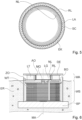
- a system for energy storage which comprises a heat exchanger arrangement WA and a water storage tank WS for storing heat.
- a water heat exchanger WT is arranged in the water storage tank WS.
- a transport medium which serves for heat exchange can be pumped through the water heat exchanger WT or the air heat exchanger LT of the heat exchanger arrangement WA by means of a heat pump (not shown). The transport medium is pumped from the heat pump into the lines LG which lead to the air heat exchanger LT and the water heat exchanger WT.
- the heat exchanger arrangement WA is arranged above the water storage tank WS with respect to the central axis MA of the housing GE.
- the water storage tank WS is arranged within a hole in the ground ER, with the air supply openings ZO of the heat exchanger arrangement WA protruding above the ground.
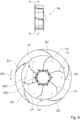
- FIG 7 A perspective view of another embodiment of a radial fan RL is shown.
- the radial fan RL has a grille GT on its top, which is similar to the one in Figure 1
- the radial fan RL has several blades SC, which can be set in a rotating motion in reverse operation RB as shown.
- the rotating motion of the blades SC brings air radially from the outside into the interior of the arrangement, so that the air can escape in the axial direction via the grille GT.
- a much smaller number of blades SC and lamellas LA is provided here.
- FIG. 8 is a cross-sectional view through the section plane A - A' of the radial fan RL as shown. It can be seen that in reverse operation several blades SC push air radially inwards. Between A tapered area is formed between the slats LA, as indicated by the distances VB1 and VB2 between two adjacent slats LA. Since a pressure increase occurs in the tapered area, the air will escape axially upwards through the grille GT without being set in rotation. In this way, a low-noise fan operation can be achieved, in which, as for an air heat exchanger LT according to Figure 1 It is advantageous to achieve an air flow radially inwards and axially upwards between the suction side and the pressure side.
- the radial fan RL is shown again in another perspective view. It can be seen that the inner tear-off edge AK of the blade SC of the radial fan RL is structured, for example jagged. This leads to a further reduction in noise. Furthermore, the tear-off edge AK is bent towards the grille GT so that the area from which the air exits is not additionally covered by the blade SC. In this way, the size of the outlet opening via the grille GT is optimized. With the measures shown, both a suitably large air flow rate can be passed through the air heat exchanger LT and very quiet or almost silent operation can be achieved. The last aspect in particular is desirable when using a heat exchanger arrangement WA, for example in private households or offices. The invention is not limited to the described embodiments, but the scope of the invention is defined exclusively by the following claims.
Landscapes
- Engineering & Computer Science (AREA)
- Mechanical Engineering (AREA)
- General Engineering & Computer Science (AREA)
- Physics & Mathematics (AREA)
- Thermal Sciences (AREA)
- Chemical & Material Sciences (AREA)
- Combustion & Propulsion (AREA)
- Heat-Exchange Devices With Radiators And Conduit Assemblies (AREA)
- Structures Of Non-Positive Displacement Pumps (AREA)
- Other Air-Conditioning Systems (AREA)
- Separation By Low-Temperature Treatments (AREA)
Description
- Die Erfindung betrifft eine Wärmetauscheranordnung.
- Die Verwendung fossiler Energieträger ist nicht nur zunehmend unwirtschaftlich, sondern wird auch aufgrund der damit verbundenen negativen Auswirkungen auf das Klima zunehmend in Frage gestellt. Neben einer Steigerung der Nutzung regenerativer Energiequellen sind daher auch effiziente Systeme zur Energiespeicherung von Nöten, die in Kombination mit intelligenten Steuerungen beispielsweise beim Heizen oder beim Kühlen von Gebäuden oder von Anlagen für einen reduzierten Energieverbrauch sorgen können. Aufgrund derartiger Maßnahmen lässt sich unabhängig vom verwendeten Energieträger ein hohes Einsparpotential schaffen, was auch die damit verbundenen Installationskosten auffängt.
- Aus der
DE 29 26 610 A1 ist ein Speicher zur Bereitstellung der Eingangswärmeenergie auf niederem Temperaturniveau für Wärmepumpenanlagen bekannt, die diese Energie aufnehmen und auf höherem Temperaturniveau wieder abgeben. Dabei ist ein Wasserbecken so gestaltet, dass sein Wasserinhalt ohne Beckenbeschädigung einfrieren kann und dass ein am Beckenboden befindliches oder in den Beckenboden eingelassenes Wärmetauschersystem erlaubt, die Abkühlungs- und Gefrierwärme dieses Beckens der Kaltseite einer Wärmepumpe zuzuführen. - Neben der Verwendung eines künstlichen Wasserbeckens ist es auch bekannt, natürliche Gewässer als Speichermedium zu nutzen.
- So ist aus der
DE 10 2015 104 909 A1 ein Energiespeicher bekannt, der einen Wärmetauscher aufweist, der auf einem vorzugweise über eine erste Zuleitung mit Wasser befüllbarem, als See ausgebildetem Unterbecken schwimmend angeordnet ist, wobei über eine zweite Zuleitung Wasser aus dem Unterbecken und über eine dritte Zuleitung den Wärmetauscher durchdringendes Kühlmittel einer Wärmepumpe in getrennten Kreisläufen zuführbar ist, so dass Energie über den Wärmetauscher unter Vereisung des Wassers des Unterbeckens oder in Form von sensibler Wärme aus dem Wasser des Unterbeckens entnehmbar und an einen Verbraucher zur Wärmeabgabe und/oder zur Kälteabgabe weiterleitbar ist. - Des Weiteren ist aus der
DE 10 2015 121 177 A1 eine schwimmende Vorrichtung zum Einbringen von Wärmeenergie in ein Gewässer sowie zum Entziehen von Wärmeenergie aus dem Gewässer bekannt, die einen Wasserwärmetauscher aufweist, der nach dem Einsetzen der Vorrichtung in das Gewässer in dieses eintaucht und einen Zulauf und einen Ablauf für eine Wärmeträgerflüssigkeit aufweist, die Wärmeenergie an das Gewässer abgeben oder dem Gewässer Wärmeenergie entziehen kann. Die Vorrichtung weist darüber hinaus einen Luftwärmetauscher auf, der von Umgebungsluft durchdrungen werden kann und darüber hinaus einen Einlass für aus dem Gewässer stammendes Wasser mit einem entsprechenden Auslass aufweist, so dass Wasser aus dem Gewässer durch den Luftwärmetauscher strömen kann, wobei Wärmeenergie zwischen der dem Luftwärmetauscher durchströmenden Umgebungsluft und dem den Luftwärmetauscher durchströmenden Wasser übertragbar ist. - Die oben beschriebenen Vorrichtungen wirken üblicherweise mit einer in einem Gebäude installierten Wärmepumpe zusammen. Diese kann beispielsweise über das Stromnetz oder einen eigenen Stromspeicher mit elektrischer Energie versorgt werden.
- Aus der
WO 2005/096715 A2 ist eine Wärmetauscheranordnung bekannt, bei der ein Radiallüfter zu einem Vorwärtsbetrieb oberhalb eines Wärmetauschers angeordnet ist, so dass die Zuluft durch den Wärmetauscher hindurch zur im Radiallüfter liegenden Saugseite transportiert wird und anschließend über die Druckseite zu einer Abluftöffnung hin transportiert wird. - In der
DE 10 2007 003 568 B4 ist eine Lüfteranordnung mit einem Radiallüfter angegeben, wobei der Radiallüfter in einem Vorwärtsbetrieb Luft entlang seiner Mittelachse ansaugt und über eine außenliegende Nachleitanordnung abgibt. - In der
DE 10 2017 102 303 A1 wird eine Vorrichtung zur Wärmegewinnung angegeben, die einen Wärmetauscher umfasst, der in einem im Erdreich versenkten Gehäuse angeordnet ist, das einen Lufteinlass und einen Luftauslass aufweist, zwischen denen ein mittels eines Lüfters erzeugter Luftstrom strömt. Der Wärmetauscher ist in dem Unterflurgehäuse angeordnet, um störende Geräuschemissionen zu vermeiden. Das Unterflurgehäuse ist innerhalb einer Erdauskofferung angeordnet, die mit einem Drainagematerial wie beispielsweise Schotter befüllt ist. - Die
JP S55 155125 A - Die
JP H09 303853 A - Insbesondere die zuletzt angeführte Schrift weist auf die Anforderungen bezüglich der entstehenden Lüftergeräusche hin.
- Da trotz der oben genannten Maßnahmen die Geräuschkulisse von Wärmetauscheranordnungen, insbesondere durch die akustischen Emissionen der Lüfter, oberhalb der Wahrnehmungsschwelle der meisten Personen liegt, stellt sich nun die Aufgabe, eine Wärmetauscheranordnung anzugeben, deren akustische Emissionen noch weiter reduziert sind.
- Diese Aufgabe wird durch die Merkmale des Patentanspruchs 1 gelöst. Weitere vorteilhafte Ausgestaltungen der Erfindung sind jeweils Gegenstand der Unteransprüche.
- Beschreibung, insbesondere im Zusammenhang mit der Zeichnung, charakterisiert und spezifiziert die Erfindung zusätzlich.
- Gemäß der Erfindung wird eine Wärmetauscheranordnung angegeben umfassend ein Gehäuse, in dem umfangseitig mindestens eine Zuluftöffnung angeordnet ist, einen Deckel, der das Gehäuse an einer Oberseite überdeckt und in dem mindestens eine Abluftöffnung angeordnet ist, wobei innerhalb des Gehäuses ein rückwärtsbetriebener Radiallüfter so angeordnet ist, dass er einen bezüglich seiner Rotationsachse radial nach innen gerichteten Luftstrom zwischen der Zuluftöffnung und der Abluftöffnung erzeugen kann, der mindestens einen im Gehäuse angeordneten Luftwärmetauscher durchströmt. Die Zuluftöffnung ist zwischen Deckel und Gehäuse angeordnet, und der durch den Radiallüfter erzeugte Luftstrom strömt durch die Abluftöffnung nach oben gerichtet ab. Es hat sich überraschenderweise herausgestellt, dass ein rückwärtslaufender Radiallüfter geeignet ist, die gewünschte Lüftungsleistung bei minimaler akustischer Emission bereitzustellen. Üblicherweise werden Radiallüfter mit einem radial nach außen gerichtetem Luftstrom im Vorwärtsbetrieb genutzt, wobei die Luft zur Rotationsachse hin angesaugt wird. Für radiales Abströmen wird typischerweise ein Axiallüfter eingesetzt. Der Vorteil des rückwärtslaufenden Radiallüfters gegenüber einem Axiallüfter ist, dass dieser mit geringer Drehzahl betrieben werden kann, so dass durch den Lüfterlauf nahezu keine wahrnehmbaren akustischen Emissionen entstehen. Unter Rückwärtslauf wird verstanden, dass die Saugseite des Radiallüfters bezüglich dessen Rotationsachse außerhalb der Schaufeln liegt, wohingegen die Druckseite bezüglich der Rotationsachse innerhalb des Radiallüfters liegt. Ein Luftstrom wird durch den Radiallüfter im Rückwärtsbetrieb demnach von der außenliegenden Saugseite zur innenliegenden Druckseite erzeugt.
- Der Luftwärmetauscher ist innerhalb eines Gehäuses angeordnet, wobei das Gehäuse eine bezüglich einer Mittelachse außenliegende Zuluftöffnung und eine innenliegende Abluftöffnung aufweist, zwischen denen mittels des Radiallüfters ein horizontaler Luftstrom erzeugt wird, der den Luftwärmetauscher durchströmt beziehungsweise an Lamellen des Luftwärmetauschers auf fachübliche Weise vorbeiströmt. Die Bezeichnung innerhalb und außerhalb bezieht sich dabei auf von der Rotationsachse des Radiallüfters ausgehende Richtungen, wobei ein Bauteil, das näher an der Rotationsachse liegt, als innenliegend bezeichnet wird. Bei der Mittelachse muss es sich nicht um die geometrische Mitte des Gehäuses handeln, vielmehr ist unter der Mittelachse ein Bezugspunkt innerhalb des Gehäuses zu verstehen, um die verlaufend von innen nach außen zunächst der Radiallüfter angeordnet ist, danach weiter außen der Luftwärmetauscher und danach weiter außen die Zuluftöffnung angeordnet ist. Üblicherweise aber nicht zwangsläufig liegen die Rotationsachse und die Mittelachse aufeinander. Die Abluftöffnung wird über der Druckseite des Radiallüfters angeordnet, so dass der auf der Saugseite horizontal erzeugte Luftstrom auf der Druckseite das Gehäuse in vertikaler Richtung verlassen kann. Die Wärmetauscheranordnung wird üblicherweise so angeordnet, dass die Rotationsachse des Radiallüfters senkrecht zum Boden ausgerichtet ist. Gegenüber den üblicherweise verwendeten Axiallüftern hat ein Radiallüfter im Rückwärtsbetrieb den Vorteil, dass dieser mit einem größeren Durchmesser ausgelegt werden kann, sodass bei niedrigen Drehzahlen und niedrigen Strömungsgeschwindigkeiten der Luft hohe Luftvolumina bewegt werden können. Der Radiallüfter wird vorteilhafterweise im Gehäuse in Richtung seiner Rotationsachse nach oben und unten umbaut. Die Umbauung kann auch Bestandteil des Gehäuses oder anderer Komponenten der Wärmetauscheranordnung sein. Der maximal transportierbare Luftstrom kann durch die Wahl der Abmessungen des Radiallüfters entsprechend vorgegeben werden. Während des Betriebs der Wärmetauscheranordnung wird von einer externen Wärmepumpe ein Trägermedium durch die Wärmetauscheranordnung gepumpt und der Radiallüfter im Rückwärtslauf betrieben. Demnach wird Umgebungsluft durch die Zuluftöffnungen in das Gehäuse gesaugt, anschließend radial durch die Luftkanäle der Lamellen des Luftwärmetauschers zum Radiallüfter geführt, dann durch den Radiallüfter zur Druckseite befördert und zuletzt axial durch die Abluftöffnung aus dem Gehäuse ausgeleitet. Der Luftwärmetauscher kann entweder umlaufend um den Radiallüfter angeordnet sein oder aber einzelne Blöcke umfassen, die um den Radiallüfter angeordnet sind. Die Zuluftöffnungen sind so angeordnet und bemessen, dass der Luftwärmetauscher von Umgebungsluft durchströmt werden kann.
- Gemäß einer Ausführungsform weist der Radiallüfter eine Vielzahl von Schaufeln auf, die von einer Nachleitanordnung mit einer Vielzahl von Lamellen umgeben sind.
- Demnach wird innerhalb des Radiallüfters eine Nachleitanordnung angeordnet, die Lamellen aufweist, die den Luftstrom auf der Druckseite des Radiallüfters zur Rotationsachse des Radiallüfters hin und/oder in Richtung der Abluftöffnungen leiten. Es hat sich überraschenderweise gezeigt, dass mittels der Nachleitanordnung die akustische Emission der Wärmetauscheranordnung abermals reduziert werden kann. Insgesamt konnten akustische Emissionen durch die gemeinsame Verwendung eines rückwärtslaufenden Radiallüfters und einer innenliegenden Nachleitanordnung bei vergleichbarer Lüfterleistung weiter reduziert werden.
- Gemäß einer weiteren Ausführungsform sind die Schaufeln des Radiallüfters und die Lamellen der Nachleitanordnung entgegengesetzt gekrümmt.
- Indem die Lamellen und die Schaufeln unterschiedlich gekrümmt sind, wird erreicht, dass die Luft an den Schaufeln des Radiallüfters abgeleitet wird. Der vom Radiallüfter kommende Luftstrom wird von der Nachleitanordnung abgestreift und in Richtung der Abluftöffnung geleitet oder zum Mittelpunkt der Nachleitanordnung, der idealer Weise mit der Rotationsachse des Radiallüfter zusammenfällt, geleitet, sodass dort ein Überdruck entsteht, der durch die Abluftöffnung entweicht. Besonders vorteilhaft ist es, wenn die Schaufeln des Radiallüfters bezogen auf den Rückwärtsbetrieb vorwärts gekrümmt sind und die Lamellen der Nachleitanordnung rückwärts gekrümmt sind.
- Gemäß einer weiteren Ausführungsform der Erfindung sind die Schaufeln des Radiallüfters und/oder die Lamellen der Nachleitanordnung entlang und parallel zu ihrer Hochachse mit gleichbleibender Krümmung ausgebildet.
- Jeweils eine Schaufel oder Lamelle weist somit einen zu ihrer Hochachse parallel versetzen Kreismittelpunkt auf, um den herum die Schaufel mit einem gleichbleibenden Radius und somit mit einer gleichbleibenden Krümmung ausgebildet ist. Alternativ könnten die Schaufeln oder Lamellen auch eine nicht gleichbleibende Krümmung aufweisen, insbesondere derart, dass die Krümmung zur Rotationsachse hin abnimmt. Der Radiallüfter ist somit vorteilhafterweise zylinderförmig ausgebildet, so dass die Hochachsen der Schaufeln parallel zueinander und parallel zur Rotationsachse angeordnet sind, wobei die Rotationsachse gleichzeitig im Wesentlichen parallel zur Mittelachse des Gehäuses ausgerichtet ist. Die Mittelachse des Gehäuses steht normal auf dem Deckel des Gehäuses. Die Nachleitanordnung weist vorteilhafterweise ebenfalls eine zylindrische Form auf, bei der die Hochachsen der Lamellen parallel zueinander und parallel zur Rotationsachse des Radiallüfters ausgerichtet sind.
- Gemäß einer weiteren Ausführungsform der Erfindung bilden sich zwischen den Lamellen (LA) nach Innen verjüngende Bereiche, so dass der Luftstrom nach Innen hin eine Druckerhöhung erfährt.
- Aufgrund dieser Konfiguration erfolgt eine Druckerhöhung des Luftstroms im Inneren, so dass auch bei niedrigen Drehzahlen eine ausreichende Durchströmung des Luftwärmetauschers im Rückwärtsbetrieb des Radiallüfters möglich ist. Dabei schieben mehrere Schaufeln die Luft radial nach Innen. Da sich im verjüngenden Bereich eine Druckerhöhung einstellt, wird die Luft, ohne in Drehbewegung versetzt zu werden, axial entweichen
- Erfindungsgemäß ist die Zuluftöffnung zwischen Deckel und Gehäuse angeordnet.
- Demnach sind die Zuluftöffnungen horizontal zur Mittelachse des Gehäuses hin verlaufend ausgerichtet. Dies hat den Vorteil, dass thermische Kurzschlüsse zwischen der Abluft und der Zuluft vermieden oder reduziert werden können. Außerdem eignet sich eine derartige Anordnung zur Verwendung mit einem System zur Energiespeicherung, wie weiter unten noch beschrieben wird.
- Gemäß einer weiteren Ausführungsform der Erfindung überdecken sich der rückwärtsbetriebene Radiallüfter und die Nachleitanordnung entlang der Rotationsachse des Radiallüfters zumindest abschnittsweise.
- Demnach liegen die Zuluftöffnungen der Luftwärmetauscher der Radiallüfter und die Nachleitanordnung zumindest entlang eines gemeinsamen Radialstrahls um die Mittelachse übereinander. Horizontal von der Zuluftöffnung zur Druckseite des Radiallüfters strömende Luft verläuft somit am Luftwärmetauscher, dem Radiallüfter und der Nachleitanordnung vorbei.
- Gemäß einer weiteren Ausführungsform der Erfindung wird der rückwärtsbetriebene Radiallüfter mittels eines Elektromotors angetrieben.
- Durch die Verwendung eines Elektromotors kann der benötigte Luftstrom auf einfache Weise variiert werden. Der Elektromotor kann in einer Isolationsschicht angeordnet sein, um vom Motor ausgehende Geräusche innerhalb des Gehäuses weitestgehend zu absorbieren.
- Vorteilhaft ist die Verwendung der Wärmetauscheranordnung zusammen mit einem Wasserspeicher. Ein solches System zur Energiespeicherung und zum Wärmeaustausch umfasst eine vorgenannte Wärmetauscheranordnung, einen Wasserspeicher zur Speicherung von Wärme, einen in den Wasserspeicher ragenden Wasserwärmetauscher und eine Wärmepumpe, die ein Medium zum Wärmetausch zwischen dem Luftwärmetauscher der Wärmetauscheranordnung und/oder dem Wasserwärmetauscher befördern kann, so dass Wärme ausgetauscht werden kann, wobei der Wasserspeicher in einem Erdloch versenkt werden kann und die Wärmetauscheranordnung in Richtung der Mittelachse des Gehäuses so auf dem Wasserspeicher angeordnet ist, dass zumindest die Zuluftöffnungen über das Erdreich hinausragen.
- Demnach wird eine der vorgenannten Wärmetauscheranordnungen mit einem Energiespeicher kombiniert. Der Energiespeicher speichert dabei Wärme innerhalb eines Wasserreservoirs bzw. kann Wärme von einer Wärmepumpe ausgehend in das Wasserreservoir abgeben. Der Betrieb des Wasserwärmetauschers, der Wärmetauscheranordnung und der Wärmepumpe wird dabei von einer Steuereinrichtung geregelt. Der Wasserspeicher und die Wärmetauscheranordnung können ein gemeinsames Gehäuse umfassen.
- Nachfolgend werden einige Ausführungsbeispiele anhand der Zeichnung näher erläutert. Es zeigen:
- Figur 1
- eine ersten Ausführungsform der Wärmetauscheranordnung in einer geschnittenen Seitenansicht,
- Figur 2
- die Wärmetauscheranordnung aus
Figur 1 in einer durch die Mittelachse geschnittenen Draufsicht, - Figur 3
- eine weitere Ausführungsform der Wärmetauscheranordnung in einer durch die Mittelachse geschnittenen Draufsicht,
- Figur 4
- einen Radiallüfter mit Nachleitanordnung gemäß einer ersten Ausführungsform in einer teilweise geschnittenen perspektivischen Darstellung,
- Figur 5
- den Radiallüfter mit Nachleitanordnung aus
Figur 4 in einer Querschnittsansicht, - Figur 6
- ein System zur Energiespeicherung in einer geschnittenen Seitenansicht,
- Figur 7
- einen Radiallüfter gemäß einer zweiten Ausführungsform in einer perspektivischen Darstellung,
- Figur 8
- den Radiallüfter aus
Figur 7 in einer Querschnittsansicht, und - Figur 9
- den Radiallüfter aus
Figur 7 in einer weiteren perspektivischen Darstellung. - In den Figuren sind gleiche oder funktional gleich wirkende Bauteile mit den gleichen Bezugszeichen versehen.
- Unter Bezugnahme auf
Figur 1 wird nachfolgend eine erste Ausführungsform einer erfindungsgemäßen Wärmetauscheranordnung WA beschrieben. Die Wärmetauscheranordnung umfasst ein Gehäuse GE mit Zuluftöffnungen ZO und bezogen auf die Zuluftöffnungen ZO innenliegende Abluftöffnungen AO, wobei die Bezeichnung innenliegend und außenliegend bezüglich einer Mittelachse MA die normal auf einem Deckel DE des Gehäuses sitzt und das Gehäuse durchdringt verwendet wird. - Von den Zuluftöffnungen ZO ausgehend innenliegend ist ein Luftwärmetauscher LT angeordnet. Noch weiter innenliegend ist ein Radiallüfter RL angeordnet an den sich innenliegend eine Nachleiteranordnung NL anschließt. Der Radiallüfter RL wird mittels einer Elektromotors MO in einem Rückwärtsbetrieb angetrieben, sodass ein Luftstrom LS von den Zuluftöffnungen ZO durch den Luftwärmetausche LT, den Radiallüfter RL und die Nachleitanordnung NL hindurch zur Abluftöffnung AO strömt. Demnach befindet sich der Luftwärmetauscher LT auf einer Saugseite SS des Radiallüfters RL, wohingegen sich die Nachleitanordnung NL und die Abluftöffnung AO auf der Druckseite DS des Radiallüfters RL befindet. Der Elektromotor MO ist innerhalb einer Isolationsschicht IS zur akustischen und/ oder thermischen Dämmung angeordnet.
- Der Luftstrom LS durchquert das Gehäuse GE von den Zuluftöffnungen ZO ausgehend weitestgehend horizontal, verlässt das Gehäuse GE durch die Abluftöffnung AO hingegen vertikal. Bei einem Vorwärtsbetrieb des Radiallüfters RL wie er gemeinhin für üblich erachtet wird wäre die Strömungsrichtung umgekehrt. So würde im vorwärts Betrieb Luft von der Rotationsachse RA des Radiallüfters RL herkommend horizontal nach außen zu den Zuluftöffnungen ZO befördert. Von einer nicht dargestellten Wärmepumpe wird ein Trägermedium zum Luftwärmetauscher LT gepumpt. In Luftkanälen LK des Luftwärmetauschers LT wird dann Wärme zwischen der Umgebungsluft und dem Trägermedium ausgetauscht.
- In
Figur 2 ist einer entlang der Achse AA geschnittene Draufsicht der Wärmetauscheranordnung ausFigur 1 dargestellt. Von außen nach innen umfasst die Wärmetauscheranordnung WA ein Gehäuse GE mit Seitenwänden SW, einen Luftwärmetauscher LT, einen Radiallüfter RL, eine Nachleitanordnung NL, eine Abluftöffnung AO. Eine Mittelachse MA des Gehäuses GE verläuft durch den Mittelpunkt der Wärmetauscheranordnung. Die Mittelachse MA läuft nicht zwangsläufig durch den geometrischen Mittelpunkt des Gehäuses GE, sondern fällt üblicherweise mit der Rotationsachse des Radiallüfters RL zusammen und bildet den Bezugspunkt zur Anordnung aller weiteren Bauteile. Die Nachleitanordnung NL ist als Stator ausgebildet, um den sich der Radiallüfter RL dreht. - In
Figur 3 wird eine alternative Ausführungsform der Wärmetauscheranordnung WA dargestellt, bei der das Gehäuse GE einen rechteckigen Querschnitt aufweist. Der Luftwärmetauscher LT ist wiederum zwischen den Zuluftöffnungen ZO und der Abluftöffnung AO angeordnet. Die Luftwärmetauscher LT befinden sich auf der Saugseite SS des rückwärtsbetriebenen Radiallüfters, wohingegen die Nachleitanordnung NL auf der Druckseite DS des Radiallüfters RL angeordnet ist. Die Luftwärmetauscher LT korrespondieren in ihrer Ausdehnung mit den Zuluftöffnungen ZO. Entlang der Auflageflächen des Deckels DE auf den Seitenwänden SW des Gehäuses GE können optional Dichtungen DI angeordnet sein, die verhindern, dass Luft durch die Spalten zwischen dem Deckel DE und den Seitenwänden SW angesaugt wird. Eine derartige Anordnung ist insbesondere bei Verwendung eines freistehenden Wärmetauscheranordnung WA vorteilhaft, die nach Aufbau von dem Gehäuse GE als Einhausung umgeben werden soll, um diese vor Beschädigung zu schützen. - In
Figur 4 ist der Radiallüfter RL und die Nachleitanordnung NL in einer perspektivischen Ansicht dargestellt, wobei Teile der Darstellung geschnitten sind. Der Radiallüfter RL weist Schaufeln SC auf, die vorwärts gekrümmt sind und deren Schaufelhochachse HS parallel zur Rotationsachse RA des Radiallüfters RL verlaufen. Die Nachleitanordnung NL weist Lamellen LA auf, die bezüglich der Drehrichtung im rückwärts Betrieb RB rückwärtsgekrümmt angeordnet sind und deren Lamellen Hochachse HL ebenfalls parallel zur Rotationsachse RA des Radiallüfters RL verlaufen. Innenliegend befindet sich aufgrund des Rückwärtsbetriebes RB die Druckseite DS, außenliegend hingegen die Saugseite SS. Während des Rückwärtsgebetriebes RB wird Luft durch die Schaufeln SC auf der Saugseite SS angezogen und in Richtung der Druckseite DS gedrückt. Die Nachleitanordnung greift den vom Radiallüfter RL erzeugten Luftstrom auf der Druckseite DS ab und leitet diesen in Richtung der Rotationsachse RA. -
Figur 5 zeigt die Anordnung aus Radiallüfter RL zusammen mit der Nachleitanordnung NL in einer Schnittansicht senkrecht zur Rotationsachse RA, welche in der gewählten Darstellung senkrecht zur Blattebene wäre. Man erkennt, dass die Lamellen LA der Nachleitanordnung NL sowie die Schaufeln SC des Radiallüfters RL so ausgebildet sind, dass sich jeweils zwischen benachbarten Unterteilungen ein Expansionskanal EK ausbildet, der für eine Druckänderung zwischen der Saugseite und der Druckseite sorgt. Aufgrund dieser Konfiguration erfolgt eine Umsetzung der Geschwindigkeit des Luftstroms zur Änderung des Drucks des Luftstroms, so dass auch bei niedrigen Drehzahlen eine ausreichende Durchströmung des Luftwärmetauschers im Rückwärtsbetrieb des Radiallüfters RL möglich ist. Der Rückwärtsbetrieb des Radiallüfters RL ist für die Anwendung bei den hier vorgestellten Luftwärmetauschern besonders gut geeignet, da sich das seitliche Einströmen von Luft über die Zuluftöffnungen ZO und das nach oben gerichtete Abströmen des Luftstroms durch die Abluftöffnungen AO perfekt mit einem rückwärts betriebenen Radiallüfter ergänzen. Besonders vorteilhaft ist die Kombination des Luftwärmetauschers LT mit einem weiteren Wärmetauscher, der in einer Flüssigkeit eingebracht ist. Ein derartiges System wird nachfolgend detaillierter vorgestellt. - In
Figur 6 wird ein System zur Energiespeicherung dargestellt, welches eine Wärmetauscheranordnung WA und einen Wasserspeicher WS zur Speicherung von Wärme umfasst. Im Wasserspeicher WS ist ein Wasserwärmetauscher WT angeordnet. Durch den Wasserwärmetauscher WT oder den Luftwärmetauscher LT der Wärmetauscheranordnung WA kann mittels einer nicht dargestellten Wärmepumpe ein Transportmedium gepumpt werden, das dem Wärmeaustausch dient. Das Transportmedium wird von der Wärmepumpe aus in die Leitungen LG gepumpt, die zum Luftwärmetauscher LT und zum Wasserwärmetauscher WT führen. Die Wärmetauscheranordnung WA ist bezüglich der Mittelachse MA des Gehäuses GE über dem Wasserspeicher WS angeordnet. Der Wasserspeicher WS ist innerhalb eines Erdlochs im Erdreicht ER angeordnet, wobei die Zuluftöffnungen ZO der Wärmetauscheranordnung WA über das Erdreich hinausragen. - In
Figur 7 ist in einer perspektivischen Darstellung eine weitere Ausführungsform eines Radiallüfters RL gezeigt. Der Radiallüfter RL weist dabei an seiner Oberseite ein Gitter GT auf, das der inFigur 1 dargestellten Austrittsöffnung AO entspricht. Der Radiallüfter RL weist wiederum mehrere Schaufel SC auf, welche in einem Rückwärtsbetrieb RB wie dargestellt in eine Drehbewegung versetzt werden können. Im Inneren befinden sich mehrere Lamellen LA. Durch die Drehbewegung der Schaufeln SC wird wiederum Luft radial von außen in das Innere der Anordnung gebracht, sodass die Luft über das Gitter GT in axialer Richtung entweichen kann. Im Gegensatz zur Ausführungsform nachFigur 4 ist hier jedoch eine wesentlich geringere Anzahl an Schaufeln SC und Lamellen LA vorgesehen. - Die Funktionsweise des Radiallüfters RL lässt sich anhand der
Figur 8 besser verdeutlichen. InFigur 8 ist eine Querschnittsansicht durch die Schnittebene A - A' des Radiallüfter RL wie dargestellt gezeigt. Man erkennt, dass im Rückwärtsbetrieb mehrere Schaufeln SC Luft radial nach Innen schieben. Zwischen den Lamellen LA bildet sich ein verjüngender Bereich aus, wie anhand der Abstände VB1 und VB2 zwischen zwei benachbarten Lamellen LA angedeutet ist. Da sich im verjüngenden Bereich eine Druckerhöhung einstellt, wird die Luft, ohne in Drehbewegung versetzt zu werden, axial nach oben durch das Gitter GT entweichen. Auf diese Weise lässt sich ein geräuscharmer Lüfterbetrieb erzeugen, bei dem wie für einen Luftwärmetauscher LT gemäßFigur 1 vorteilhaft ist, eine Luftströmung radial nach innen und axial nach oben zwischen der Saugseite und der Druckseite erreichen. - In
Figur 9 ist der Radiallüfter RL nochmals in einer weiteren perspektivischen Darstellung gezeigt. Man erkennt, dass die innen liegenden Abrisskante AK der Schaufel SC des Radiallüfters RL mit einer Strukturierung, beispielsweise gezackt ausgebildet ist. Dies führt zu einer weitern Geräuschreduzierung. Des Weiteren ist die Abrisskante AK zum Gitter GT hingebogen ausgeführt, sodass der Bereich, aus dem die Luft austritt, nicht zusätzlich durch die Schaufel SC bedeckt wird. Auf diese Weise wird die Größe der Austrittsöffnung über das Gitter GT optimiert. Mit gezeigten Maßnahmen lässt sich sowohl eine geeignet große Luftfördermenge durch den Luftwärmetauscher LT führen als auch ein sehr geräuscharmer oder nahezu geräuschloser Betrieb erreichen. Insbesondere der letzte Aspekt ist bei dem Einsatz einer Wärmetauscheranordnung WA beispielsweise bei Privathaushalten oder bei Büros wünschenswert. Der Erfindung ist nicht auf die beschriebenen Ausführungsbeispiele beschränkt, aber der Schutzumfang der Erfindung wird ausschließlich durch die folgenden Ansprüche definiert.
Claims (9)
- Wärmetauscheranordnung (WA) umfassend ein Gehäuse (GE), in dem umfangseitig eine Zuluftöffnung (ZO) angeordnet ist, einen Deckel (DE), der das Gehäuse (GE) an einer Oberseite überdeckt und in dem eine Abluftöffnung (AO) angeordnet ist, wobei innerhalb des Gehäuses (GE) ein rückwärtsbetriebener Radiallüfter (RL) so angeordnet ist, dass er einen bezüglich seiner Rotationsachse (RA) radial nach innen gerichteten Luftstrom zwischen der Zuluftöffnung (ZO) und der Abluftöffnung (AO) erzeugen kann, der mindestens einen im Gehäuse (GE) angeordneten Luftwärmetauscher (LT) durchströmt,
dadurch gekennzeichnet,
dass die Zuluftöffnung (ZO) zwischen Deckel (DE) und Gehäuse (GE) angeordnet ist und dass im Betrieb der durch den Radiallüfter (RL) erzeugte Luftstrom durch die Abluftöffnung (AO) nach oben gerichtet abströmt. - Wärmetauscheranordnung nach Anspruch 1, bei der der Radiallüfter (RL) eine Vielzahl von Schaufeln (SC) aufweist, die von einer Nachleitanordnung (NL) mit einer Vielzahl von Lamellen (LA) umgeben sind.
- Wärmetauscheranordnung nach Anspruch 1 oder 2, bei der die Schaufeln (SC) des Radiallüfters (RL) und die Lamellen (LA) der Nachleitanordnung (NL) entgegengesetzt gekrümmt sind.
- Wärmetauscheranordnung nach einem der Ansprüche 2 oder 3, bei der die Schaufeln (SC) des Radiallüfters (RL) entlang und parallel zu ihrer Hochachse (HS) mit gleichbleibender Krümmung ausgebildet sind.
- Wärmetauscheranordnung nach einem der Ansprüche 2 bis 4, bei der die Lamellen (LA) der Nachleitanordnung (NL) entlang und parallel zu ihrer Hochachse (HL) mit gleichbleibender Krümmung ausgebildet sind.
- Wärmetauscheranordnung nach einem der Ansprüche 2 bis 5, bei der sich zwischen den Lamellen (LA) nach Innen verjüngende Bereiche bilden, so dass der Luftstrom nach Innen hin eine Druckerhöhung erfährt.
- Wärmetauscheranordnung nach einem der Ansprüche 1 bis 6, bei der sich der rückwärtsbetriebene Radiallüfter (RL) und die Nachleitanordnung (NL) entlang der Rotationsachse (RA) des Radiallüfters (RL) zumindest abschnittsweise überdecken.
- Wärmetauscheranordnung nach einem der Ansprüche 1 bis 7, bei der die Zuluftöffnung (ZO) in einer Seitenwand (SW) des Gehäuses (GE) angeordnet ist, welches einen freistehenden Luftwärmetauscher (LT) umgibt.
- Wärmetauscheranordnung nach einem der Ansprüche 1 bis 8, bei der der rückwärtsbetriebene Radiallüfter (RL) mittels eines Elektromotors (EM) angetrieben ist.
Applications Claiming Priority (3)
| Application Number | Priority Date | Filing Date | Title |
|---|---|---|---|
| DE102020108377.7A DE102020108377A1 (de) | 2020-03-26 | 2020-03-26 | Wärmetauscheranordnung |
| DE102020125030 | 2020-09-25 | ||
| PCT/EP2021/057787 WO2021191371A1 (de) | 2020-03-26 | 2021-03-25 | Wärmetauscheranordnung |
Publications (3)
| Publication Number | Publication Date |
|---|---|
| EP4127481A1 EP4127481A1 (de) | 2023-02-08 |
| EP4127481C0 EP4127481C0 (de) | 2024-12-18 |
| EP4127481B1 true EP4127481B1 (de) | 2024-12-18 |
Family
ID=75362583
Family Applications (1)
| Application Number | Title | Priority Date | Filing Date |
|---|---|---|---|
| EP21716107.4A Active EP4127481B1 (de) | 2020-03-26 | 2021-03-25 | Wärmetauscheranordnung |
Country Status (10)
| Country | Link |
|---|---|
| US (1) | US12281848B2 (de) |
| EP (1) | EP4127481B1 (de) |
| JP (1) | JP2023520325A (de) |
| KR (1) | KR20220152329A (de) |
| CN (1) | CN115335604A (de) |
| AU (1) | AU2021241883A1 (de) |
| BR (1) | BR112022019287A2 (de) |
| CA (1) | CA3176473A1 (de) |
| WO (1) | WO2021191371A1 (de) |
| ZA (1) | ZA202211456B (de) |
Families Citing this family (2)
| Publication number | Priority date | Publication date | Assignee | Title |
|---|---|---|---|---|
| KR102846234B1 (ko) * | 2022-12-29 | 2025-08-18 | 동우에이치에스티 주식회사 | 열처리용 냉각장치 |
| WO2025014026A1 (ko) * | 2023-07-11 | 2025-01-16 | 한온시스템 주식회사 | 차량용 블로워 유닛 |
Family Cites Families (19)
| Publication number | Priority date | Publication date | Assignee | Title |
|---|---|---|---|---|
| DE838188C (de) | 1950-08-12 | 1952-05-05 | Köln Dipl.-Ing. Max Adolf Müller | Radial von außen nach innen durchströmter Tragflügelverdichter |
| US2944801A (en) | 1955-05-09 | 1960-07-12 | Katz Robert | Rotary interchanger with direct interfacial fluid contact |
| JPS595800B2 (ja) * | 1977-12-20 | 1984-02-07 | 三菱重工業株式会社 | 求心フアン |
| JPS55155125A (en) | 1979-05-21 | 1980-12-03 | Toshiba Corp | Indoor unit for room air conditioner |
| DE2926610A1 (de) | 1979-07-02 | 1981-01-22 | Karl Schwarz | Wasser-eis-speicher zur bereitstellung der eingangsenergie fuer waermepumpen-anlagen insbesondere in verbindung mit solar-anlagen |
| JPS572939A (en) * | 1980-06-06 | 1982-01-08 | Nippon Denso Co Ltd | Air conditioning apparatus |
| JPS59593A (ja) * | 1982-06-25 | 1984-01-05 | Daikin Ind Ltd | 送風機 |
| US4876492A (en) * | 1988-02-26 | 1989-10-24 | General Electric Company | Electronically commutated motor driven apparatus including an impeller in a housing driven by a stator on the housing |
| JP3612863B2 (ja) | 1996-05-08 | 2005-01-19 | ダイキン工業株式会社 | 空気調和機の室内機 |
| JP2002364893A (ja) * | 2001-06-07 | 2002-12-18 | Matsushita Electric Ind Co Ltd | サーキュレータ |
| US7079394B2 (en) * | 2003-01-08 | 2006-07-18 | Lenovo (Singapore) Pte. Ltd. | Compact cooling device |
| KR20050099352A (ko) | 2004-04-09 | 2005-10-13 | 엘지전자 주식회사 | 전면 흡토출 방식의 공기조화기용 실외기 |
| DE102007003568B4 (de) | 2007-01-24 | 2012-08-30 | Minebea Co., Ltd. | Kühlvorrichtung für eine zu kühlende elektronische Einrichtung |
| DE102007031421B4 (de) * | 2007-07-05 | 2018-02-22 | Al-Ko Therm Gmbh | Deckenklimagerät |
| CN102245975B (zh) * | 2008-12-15 | 2014-04-16 | 大金工业株式会社 | 天花板埋入型空调室内机 |
| GB2528890B (en) * | 2014-08-01 | 2019-03-06 | Arup Ventures Ltd | Air conditioning unit |
| DE102015104909B3 (de) | 2015-03-30 | 2016-09-29 | MBS Naturstromspeicher GmbH | Energiespeicher, Kraftwerksanlage mit Energiespeicher und Verfahren zum Betrieb desselben |
| DE102015121177A1 (de) | 2015-12-04 | 2017-06-08 | Naturspeicher Gmbh | Verfahren und Vorrichtung zum Einbringen und zur Entnahme von Wärmeenergie in bzw. aus einem Gewässer |
| AT517936B1 (de) | 2016-02-23 | 2017-06-15 | Guntamatic Heiztechnik Gmbh | Vorrichtung zur Wärmegewinnung |
-
2021
- 2021-03-25 EP EP21716107.4A patent/EP4127481B1/de active Active
- 2021-03-25 KR KR1020227036737A patent/KR20220152329A/ko not_active Ceased
- 2021-03-25 BR BR112022019287A patent/BR112022019287A2/pt unknown
- 2021-03-25 CA CA3176473A patent/CA3176473A1/en active Pending
- 2021-03-25 WO PCT/EP2021/057787 patent/WO2021191371A1/de not_active Ceased
- 2021-03-25 JP JP2022557697A patent/JP2023520325A/ja active Pending
- 2021-03-25 CN CN202180023803.7A patent/CN115335604A/zh active Pending
- 2021-03-25 US US17/913,966 patent/US12281848B2/en active Active
- 2021-03-25 AU AU2021241883A patent/AU2021241883A1/en active Pending
-
2022
- 2022-10-19 ZA ZA2022/11456A patent/ZA202211456B/en unknown
Also Published As
| Publication number | Publication date |
|---|---|
| BR112022019287A2 (pt) | 2022-11-16 |
| CN115335604A (zh) | 2022-11-11 |
| CA3176473A1 (en) | 2021-09-30 |
| US20230121916A1 (en) | 2023-04-20 |
| EP4127481C0 (de) | 2024-12-18 |
| EP4127481A1 (de) | 2023-02-08 |
| JP2023520325A (ja) | 2023-05-17 |
| US12281848B2 (en) | 2025-04-22 |
| KR20220152329A (ko) | 2022-11-15 |
| AU2021241883A1 (en) | 2022-10-20 |
| ZA202211456B (en) | 2023-06-28 |
| WO2021191371A1 (de) | 2021-09-30 |
Similar Documents
| Publication | Publication Date | Title |
|---|---|---|
| EP4127481B1 (de) | Wärmetauscheranordnung | |
| EP1525396B2 (de) | Windturbine mit einem geschlossenen kühlkreislauf | |
| DE1528862A1 (de) | Abwasserpumpe od.dgl. | |
| EP2661558B1 (de) | Motorpumpeneinheit für ein hochdruckreinigungsgerät sowie hochdruckreinigungsgerät | |
| EP2715918A2 (de) | Elektrische maschine mit rotorinnenbelüftung | |
| DE112012006221T5 (de) | System und Verfahren zum Kühlen eines Elektromotors | |
| DE10047387A1 (de) | Elektrisch angetriebene Kühlmittelpumpe | |
| DE60036336T2 (de) | Turbomaschinen | |
| DE102013214082A1 (de) | Elektrischer Gondelantrieb für ein Schiff | |
| DE102011078791A1 (de) | Geschlossene elektrische Maschine mit Rotorwellenbelüftung | |
| EP2516868B1 (de) | Wasserturbine oder wasserpumpe oder sonstige hydraulische maschine | |
| DE102011107829A1 (de) | Pumpturbinenanlage | |
| DE102020209761A1 (de) | Elektrisches Antriebssystem | |
| DE3424497A1 (de) | Geblaesediffusor- und kollektoranordnung fuer kuehlsysteme in dynamoelektrischen maschinen | |
| DE102020108377A1 (de) | Wärmetauscheranordnung | |
| DE2363166A1 (de) | Hydraulische maschine | |
| EP2888804B1 (de) | Elektrische maschine und verfahren zum kühlen einer elektrischen maschine | |
| EP4264058B1 (de) | Impellermaschine | |
| DE102007036032A1 (de) | Unterwassermotor mit Wärmetauscher | |
| DE1703433A1 (de) | Tauchpumpenaggregat mit ueberflutbarer Antriebseinrichtung | |
| DE9101715U1 (de) | Axiallüftereinheit | |
| DE2142288C3 (de) | Langsamlaufender, mit an der Lüfternabe angeordneten Axialflügeln ausgestatteter Großventilator | |
| DE102012024251B4 (de) | Rotorvorrichtung für eine Brennstoffheizung mit einer koaxial in einer Zuluftleitung angeordneten Abluftleitung | |
| DE3013374C2 (de) | Lüftungsvorrichtung mit einem Wärmeübertrager zum Übertragen von Abluftwärme auf die Zuluft | |
| DE102023210201A1 (de) | Gebläse für eine Brennstoffzellenanordnung |
Legal Events
| Date | Code | Title | Description |
|---|---|---|---|
| STAA | Information on the status of an ep patent application or granted ep patent |
Free format text: STATUS: UNKNOWN |
|
| STAA | Information on the status of an ep patent application or granted ep patent |
Free format text: STATUS: THE INTERNATIONAL PUBLICATION HAS BEEN MADE |
|
| PUAI | Public reference made under article 153(3) epc to a published international application that has entered the european phase |
Free format text: ORIGINAL CODE: 0009012 |
|
| STAA | Information on the status of an ep patent application or granted ep patent |
Free format text: STATUS: REQUEST FOR EXAMINATION WAS MADE |
|
| 17P | Request for examination filed |
Effective date: 20221026 |
|
| AK | Designated contracting states |
Kind code of ref document: A1 Designated state(s): AL AT BE BG CH CY CZ DE DK EE ES FI FR GB GR HR HU IE IS IT LI LT LU LV MC MK MT NL NO PL PT RO RS SE SI SK SM TR |
|
| DAV | Request for validation of the european patent (deleted) | ||
| DAX | Request for extension of the european patent (deleted) | ||
| GRAP | Despatch of communication of intention to grant a patent |
Free format text: ORIGINAL CODE: EPIDOSNIGR1 |
|
| STAA | Information on the status of an ep patent application or granted ep patent |
Free format text: STATUS: GRANT OF PATENT IS INTENDED |
|
| RIC1 | Information provided on ipc code assigned before grant |
Ipc: F24V 50/00 20180101ALI20240809BHEP Ipc: F24F 12/00 20060101ALI20240809BHEP Ipc: F24F 1/0022 20190101ALI20240809BHEP Ipc: F24T 10/30 20180101ALI20240809BHEP Ipc: F28D 1/02 20060101ALI20240809BHEP Ipc: F04D 29/58 20060101ALI20240809BHEP Ipc: F04D 29/42 20060101ALI20240809BHEP Ipc: F04D 17/02 20060101AFI20240809BHEP |
|
| INTG | Intention to grant announced |
Effective date: 20240828 |
|
| GRAS | Grant fee paid |
Free format text: ORIGINAL CODE: EPIDOSNIGR3 |
|
| GRAA | (expected) grant |
Free format text: ORIGINAL CODE: 0009210 |
|
| STAA | Information on the status of an ep patent application or granted ep patent |
Free format text: STATUS: THE PATENT HAS BEEN GRANTED |
|
| AK | Designated contracting states |
Kind code of ref document: B1 Designated state(s): AL AT BE BG CH CY CZ DE DK EE ES FI FR GB GR HR HU IE IS IT LI LT LU LV MC MK MT NL NO PL PT RO RS SE SI SK SM TR |
|
| REG | Reference to a national code |
Ref country code: CH Ref legal event code: EP |
|
| REG | Reference to a national code |
Ref country code: DE Ref legal event code: R096 Ref document number: 502021006159 Country of ref document: DE |
|
| REG | Reference to a national code |
Ref country code: IE Ref legal event code: FG4D Free format text: LANGUAGE OF EP DOCUMENT: GERMAN |
|
| U01 | Request for unitary effect filed |
Effective date: 20250117 |
|
| U07 | Unitary effect registered |
Designated state(s): AT BE BG DE DK EE FI FR IT LT LU LV MT NL PT RO SE SI Effective date: 20250123 |
|
| PG25 | Lapsed in a contracting state [announced via postgrant information from national office to epo] |
Ref country code: HR Free format text: LAPSE BECAUSE OF FAILURE TO SUBMIT A TRANSLATION OF THE DESCRIPTION OR TO PAY THE FEE WITHIN THE PRESCRIBED TIME-LIMIT Effective date: 20241218 |
|
| PG25 | Lapsed in a contracting state [announced via postgrant information from national office to epo] |
Ref country code: NO Free format text: LAPSE BECAUSE OF FAILURE TO SUBMIT A TRANSLATION OF THE DESCRIPTION OR TO PAY THE FEE WITHIN THE PRESCRIBED TIME-LIMIT Effective date: 20250318 |
|
| PG25 | Lapsed in a contracting state [announced via postgrant information from national office to epo] |
Ref country code: GR Free format text: LAPSE BECAUSE OF FAILURE TO SUBMIT A TRANSLATION OF THE DESCRIPTION OR TO PAY THE FEE WITHIN THE PRESCRIBED TIME-LIMIT Effective date: 20250319 |
|
| PG25 | Lapsed in a contracting state [announced via postgrant information from national office to epo] |
Ref country code: RS Free format text: LAPSE BECAUSE OF FAILURE TO SUBMIT A TRANSLATION OF THE DESCRIPTION OR TO PAY THE FEE WITHIN THE PRESCRIBED TIME-LIMIT Effective date: 20250318 |
|
| U20 | Renewal fee for the european patent with unitary effect paid |
Year of fee payment: 5 Effective date: 20250423 |
|
| PG25 | Lapsed in a contracting state [announced via postgrant information from national office to epo] |
Ref country code: SM Free format text: LAPSE BECAUSE OF FAILURE TO SUBMIT A TRANSLATION OF THE DESCRIPTION OR TO PAY THE FEE WITHIN THE PRESCRIBED TIME-LIMIT Effective date: 20241218 |
|
| PG25 | Lapsed in a contracting state [announced via postgrant information from national office to epo] |
Ref country code: PL Free format text: LAPSE BECAUSE OF FAILURE TO SUBMIT A TRANSLATION OF THE DESCRIPTION OR TO PAY THE FEE WITHIN THE PRESCRIBED TIME-LIMIT Effective date: 20241218 |
|
| PG25 | Lapsed in a contracting state [announced via postgrant information from national office to epo] |
Ref country code: ES Free format text: LAPSE BECAUSE OF FAILURE TO SUBMIT A TRANSLATION OF THE DESCRIPTION OR TO PAY THE FEE WITHIN THE PRESCRIBED TIME-LIMIT Effective date: 20241218 |
|
| PG25 | Lapsed in a contracting state [announced via postgrant information from national office to epo] |
Ref country code: IS Free format text: LAPSE BECAUSE OF FAILURE TO SUBMIT A TRANSLATION OF THE DESCRIPTION OR TO PAY THE FEE WITHIN THE PRESCRIBED TIME-LIMIT Effective date: 20250418 |
|
| PG25 | Lapsed in a contracting state [announced via postgrant information from national office to epo] |
Ref country code: SK Free format text: LAPSE BECAUSE OF FAILURE TO SUBMIT A TRANSLATION OF THE DESCRIPTION OR TO PAY THE FEE WITHIN THE PRESCRIBED TIME-LIMIT Effective date: 20241218 |
|
| PG25 | Lapsed in a contracting state [announced via postgrant information from national office to epo] |
Ref country code: CZ Free format text: LAPSE BECAUSE OF FAILURE TO SUBMIT A TRANSLATION OF THE DESCRIPTION OR TO PAY THE FEE WITHIN THE PRESCRIBED TIME-LIMIT Effective date: 20241218 |
|
| PG25 | Lapsed in a contracting state [announced via postgrant information from national office to epo] |
Ref country code: MC Free format text: LAPSE BECAUSE OF FAILURE TO SUBMIT A TRANSLATION OF THE DESCRIPTION OR TO PAY THE FEE WITHIN THE PRESCRIBED TIME-LIMIT Effective date: 20241218 |
|
| REG | Reference to a national code |
Ref country code: CH Ref legal event code: H13 Free format text: ST27 STATUS EVENT CODE: U-0-0-H10-H13 (AS PROVIDED BY THE NATIONAL OFFICE) Effective date: 20251023 |
|
| PLBE | No opposition filed within time limit |
Free format text: ORIGINAL CODE: 0009261 |
|
| STAA | Information on the status of an ep patent application or granted ep patent |
Free format text: STATUS: NO OPPOSITION FILED WITHIN TIME LIMIT |
|
| 26N | No opposition filed |
Effective date: 20250919 |
|
| GBPC | Gb: european patent ceased through non-payment of renewal fee |
Effective date: 20250325 |
|
| PG25 | Lapsed in a contracting state [announced via postgrant information from national office to epo] |
Ref country code: GB Free format text: LAPSE BECAUSE OF NON-PAYMENT OF DUE FEES Effective date: 20250325 |
|
| PG25 | Lapsed in a contracting state [announced via postgrant information from national office to epo] |
Ref country code: CH Free format text: LAPSE BECAUSE OF NON-PAYMENT OF DUE FEES Effective date: 20250331 |
|
| PG25 | Lapsed in a contracting state [announced via postgrant information from national office to epo] |
Ref country code: IE Free format text: LAPSE BECAUSE OF NON-PAYMENT OF DUE FEES Effective date: 20250325 |