EP4127352B1 - Plattenelement zur verkleidung einer decke und/oder wand sowie verkleidung für eine decke und/oder wand - Google Patents
Plattenelement zur verkleidung einer decke und/oder wand sowie verkleidung für eine decke und/oder wand Download PDFInfo
- Publication number
- EP4127352B1 EP4127352B1 EP20728444.9A EP20728444A EP4127352B1 EP 4127352 B1 EP4127352 B1 EP 4127352B1 EP 20728444 A EP20728444 A EP 20728444A EP 4127352 B1 EP4127352 B1 EP 4127352B1
- Authority
- EP
- European Patent Office
- Prior art keywords
- retaining
- spring
- transport position
- panel element
- retaining spring
- Prior art date
- Legal status (The legal status is an assumption and is not a legal conclusion. Google has not performed a legal analysis and makes no representation as to the accuracy of the status listed.)
- Active
Links
Images
Classifications
-
- E—FIXED CONSTRUCTIONS
- E04—BUILDING
- E04F—FINISHING WORK ON BUILDINGS, e.g. STAIRS, FLOORS
- E04F13/00—Coverings or linings, e.g. for walls or ceilings
- E04F13/07—Coverings or linings, e.g. for walls or ceilings composed of covering or lining elements; Sub-structures therefor; Fastening means therefor
- E04F13/08—Coverings or linings, e.g. for walls or ceilings composed of covering or lining elements; Sub-structures therefor; Fastening means therefor composed of a plurality of similar covering or lining elements
- E04F13/0801—Separate fastening elements
- E04F13/0803—Separate fastening elements with load-supporting elongated furring elements between wall and covering elements
- E04F13/081—Separate fastening elements with load-supporting elongated furring elements between wall and covering elements with additional fastening elements between furring elements and covering elements
- E04F13/0812—Separate fastening elements with load-supporting elongated furring elements between wall and covering elements with additional fastening elements between furring elements and covering elements fixed by means of spring action
-
- E—FIXED CONSTRUCTIONS
- E04—BUILDING
- E04B—GENERAL BUILDING CONSTRUCTIONS; WALLS, e.g. PARTITIONS; ROOFS; FLOORS; CEILINGS; INSULATION OR OTHER PROTECTION OF BUILDINGS
- E04B9/00—Ceilings; Construction of ceilings, e.g. false ceilings; Ceiling construction with regard to insulation
- E04B9/003—Ceilings; Construction of ceilings, e.g. false ceilings; Ceiling construction with regard to insulation with movable parts, e.g. pivoting panels, access doors
-
- E—FIXED CONSTRUCTIONS
- E04—BUILDING
- E04F—FINISHING WORK ON BUILDINGS, e.g. STAIRS, FLOORS
- E04F13/00—Coverings or linings, e.g. for walls or ceilings
- E04F13/07—Coverings or linings, e.g. for walls or ceilings composed of covering or lining elements; Sub-structures therefor; Fastening means therefor
- E04F13/08—Coverings or linings, e.g. for walls or ceilings composed of covering or lining elements; Sub-structures therefor; Fastening means therefor composed of a plurality of similar covering or lining elements
- E04F13/0801—Separate fastening elements
- E04F13/0803—Separate fastening elements with load-supporting elongated furring elements between wall and covering elements
- E04F13/081—Separate fastening elements with load-supporting elongated furring elements between wall and covering elements with additional fastening elements between furring elements and covering elements
- E04F13/083—Hooking means on the back side of the covering elements
-
- E—FIXED CONSTRUCTIONS
- E04—BUILDING
- E04F—FINISHING WORK ON BUILDINGS, e.g. STAIRS, FLOORS
- E04F13/00—Coverings or linings, e.g. for walls or ceilings
- E04F13/07—Coverings or linings, e.g. for walls or ceilings composed of covering or lining elements; Sub-structures therefor; Fastening means therefor
- E04F13/08—Coverings or linings, e.g. for walls or ceilings composed of covering or lining elements; Sub-structures therefor; Fastening means therefor composed of a plurality of similar covering or lining elements
- E04F13/0801—Separate fastening elements
- E04F13/0832—Separate fastening elements without load-supporting elongated furring elements between wall and covering elements
- E04F13/0833—Separate fastening elements without load-supporting elongated furring elements between wall and covering elements not adjustable
- E04F13/0846—Separate fastening elements without load-supporting elongated furring elements between wall and covering elements not adjustable the fastening elements engaging holes or grooves in the side faces of the covering elements
- E04F13/0848—Separate fastening elements without load-supporting elongated furring elements between wall and covering elements not adjustable the fastening elements engaging holes or grooves in the side faces of the covering elements specially adapted for thin sheet-like materials, e.g. sheet-metal or plastics
-
- E—FIXED CONSTRUCTIONS
- E04—BUILDING
- E04F—FINISHING WORK ON BUILDINGS, e.g. STAIRS, FLOORS
- E04F13/00—Coverings or linings, e.g. for walls or ceilings
- E04F13/07—Coverings or linings, e.g. for walls or ceilings composed of covering or lining elements; Sub-structures therefor; Fastening means therefor
- E04F13/08—Coverings or linings, e.g. for walls or ceilings composed of covering or lining elements; Sub-structures therefor; Fastening means therefor composed of a plurality of similar covering or lining elements
- E04F13/0801—Separate fastening elements
- E04F13/0832—Separate fastening elements without load-supporting elongated furring elements between wall and covering elements
- E04F13/0833—Separate fastening elements without load-supporting elongated furring elements between wall and covering elements not adjustable
- E04F13/0851—Hooking means on the back side of the covering elements
-
- E—FIXED CONSTRUCTIONS
- E04—BUILDING
- E04F—FINISHING WORK ON BUILDINGS, e.g. STAIRS, FLOORS
- E04F13/00—Coverings or linings, e.g. for walls or ceilings
- E04F13/07—Coverings or linings, e.g. for walls or ceilings composed of covering or lining elements; Sub-structures therefor; Fastening means therefor
- E04F13/08—Coverings or linings, e.g. for walls or ceilings composed of covering or lining elements; Sub-structures therefor; Fastening means therefor composed of a plurality of similar covering or lining elements
- E04F13/0801—Separate fastening elements
- E04F13/0832—Separate fastening elements without load-supporting elongated furring elements between wall and covering elements
- E04F13/0858—Separate fastening elements without load-supporting elongated furring elements between wall and covering elements fixed by means of spring action
-
- E—FIXED CONSTRUCTIONS
- E04—BUILDING
- E04B—GENERAL BUILDING CONSTRUCTIONS; WALLS, e.g. PARTITIONS; ROOFS; FLOORS; CEILINGS; INSULATION OR OTHER PROTECTION OF BUILDINGS
- E04B9/00—Ceilings; Construction of ceilings, e.g. false ceilings; Ceiling construction with regard to insulation
- E04B9/04—Ceilings; Construction of ceilings, e.g. false ceilings; Ceiling construction with regard to insulation comprising slabs, panels, sheets or the like
- E04B9/0435—Ceilings; Construction of ceilings, e.g. false ceilings; Ceiling construction with regard to insulation comprising slabs, panels, sheets or the like having connection means at the edges
-
- E—FIXED CONSTRUCTIONS
- E04—BUILDING
- E04B—GENERAL BUILDING CONSTRUCTIONS; WALLS, e.g. PARTITIONS; ROOFS; FLOORS; CEILINGS; INSULATION OR OTHER PROTECTION OF BUILDINGS
- E04B9/00—Ceilings; Construction of ceilings, e.g. false ceilings; Ceiling construction with regard to insulation
- E04B9/04—Ceilings; Construction of ceilings, e.g. false ceilings; Ceiling construction with regard to insulation comprising slabs, panels, sheets or the like
- E04B9/0478—Ceilings; Construction of ceilings, e.g. false ceilings; Ceiling construction with regard to insulation comprising slabs, panels, sheets or the like of the tray type
-
- E—FIXED CONSTRUCTIONS
- E04—BUILDING
- E04B—GENERAL BUILDING CONSTRUCTIONS; WALLS, e.g. PARTITIONS; ROOFS; FLOORS; CEILINGS; INSULATION OR OTHER PROTECTION OF BUILDINGS
- E04B9/00—Ceilings; Construction of ceilings, e.g. false ceilings; Ceiling construction with regard to insulation
- E04B9/22—Connection of slabs, panels, sheets or the like to the supporting construction
- E04B9/24—Connection of slabs, panels, sheets or the like to the supporting construction with the slabs, panels, sheets or the like positioned on the upperside of, or held against the underside of the horizontal flanges of the supporting construction or accessory means connected thereto
- E04B9/26—Connection of slabs, panels, sheets or the like to the supporting construction with the slabs, panels, sheets or the like positioned on the upperside of, or held against the underside of the horizontal flanges of the supporting construction or accessory means connected thereto by means of snap action of elastically deformable elements held against the underside of the supporting construction
-
- E—FIXED CONSTRUCTIONS
- E04—BUILDING
- E04F—FINISHING WORK ON BUILDINGS, e.g. STAIRS, FLOORS
- E04F13/00—Coverings or linings, e.g. for walls or ceilings
- E04F13/07—Coverings or linings, e.g. for walls or ceilings composed of covering or lining elements; Sub-structures therefor; Fastening means therefor
- E04F13/08—Coverings or linings, e.g. for walls or ceilings composed of covering or lining elements; Sub-structures therefor; Fastening means therefor composed of a plurality of similar covering or lining elements
- E04F13/12—Coverings or linings, e.g. for walls or ceilings composed of covering or lining elements; Sub-structures therefor; Fastening means therefor composed of a plurality of similar covering or lining elements of metal or with an outer layer of metal or enameled metal
-
- E—FIXED CONSTRUCTIONS
- E04—BUILDING
- E04F—FINISHING WORK ON BUILDINGS, e.g. STAIRS, FLOORS
- E04F2201/00—Joining sheets or plates or panels
- E04F2201/05—Separate connectors or inserts, e.g. pegs, pins, keys or strips
-
- E—FIXED CONSTRUCTIONS
- E04—BUILDING
- E04F—FINISHING WORK ON BUILDINGS, e.g. STAIRS, FLOORS
- E04F2201/00—Joining sheets or plates or panels
- E04F2201/05—Separate connectors or inserts, e.g. pegs, pins, keys or strips
- E04F2201/0523—Separate tongues; Interlocking keys, e.g. joining mouldings of circular, square or rectangular shape
- E04F2201/0547—Separate tongues; Interlocking keys, e.g. joining mouldings of circular, square or rectangular shape adapted to be moved perpendicular to the joint edge
Definitions
- the invention relates to a plate element for cladding a ceiling and/or wall and to cladding for a ceiling and/or wall.
- a plate element with the features of the preamble of claim 1 is from the publication WO 2015/183 632 A1 previously known. From the publication US 2016 145 863 A1 For example, a suspended ceiling system is known which includes ceiling panels attached to a grid arrangement.
- the retaining springs are pre-assembled on a cover plate of such a plate element. Although this has advantages when assembling the plate elements, it can make handling the plate elements more difficult during storage and transport.
- the object of the invention is therefore to provide a plate element for cladding a ceiling and/or wall, which is characterized by easy handling.
- a plate element for cladding a ceiling and/or wall which has the means and features of the independent claim directed to such a plate element.
- a plate element for cladding a ceiling and / or a wall which has a cover plate and at least one retaining spring, which is used for preferably hanging fastening of the ceiling plate to a ceiling and / or wall from a transport position to a fastening position can be moved.
- the plate element comprises a holding device for the at least one holding spring, which according to the invention is designed to fix the at least one holding spring in its transport position.
- the holding device can be designed to fix the retaining spring in its transport position under tension.
- the at least one retaining spring can be fixed to the cover plate in the transport position.
- the cover plate is preferably rectangular.
- the retaining spring initially remains in its transport position during the handling of the plate element during transport, storage and assembly of the plate element. This prevents the plate element from being damaged by the retaining spring.
- the holding device is designed to tension the at least one holding spring in its transport position. This means that the retaining spring can be fixed particularly reliably in its transport position.
- the at least one retaining spring is in the transport position due to its own spring force Holding device fixed.
- the spring force provided by the retaining spring can thus be used to fix the retaining spring in its transport position. This can simplify the design of the holding device accordingly.
- the retaining spring can also be fixed in its fastening position by its own spring force.
- the holding device itself has no moving parts.
- the holding device is designed as a preferably static abutment in order to fix the at least one retaining spring in its transport position, preferably tensioned by its own spring force.
- the retaining spring in its transport position is closer to one side of the cover plate, namely a rear side of the cover plate, in comparison to its fastening position, in particular with its spring legs.
- This side can be a side of the cover plate that is not a visible side of the plate element.
- the retaining spring In its transport position, the retaining spring can rest on this side of the cover plate, which preferably does not represent a visible side of the plate element.
- the retaining spring and in particular its spring legs can be aligned parallel or approximately parallel to this side of the cover plate in the transport position.
- the at least one retaining spring can thus be securely fixed in its transport position on a side of the cover plate that is not a visible side of the plate element. This can be caused by at least one retaining spring Damage to the visible side of the plate element can be avoided during handling, during transport and/or storage and even during assembly of the plate element.
- the visible side of the plate element can be a side that remains visible when the plate element is in the installed position of use.
- the spring legs of the at least one retaining spring can be at a greater distance from one another in the fastening position, i.e. when they are moved from their transport position to fasten the plate element to a ceiling and/or wall, than in their transport position with the retaining spring tensioned.
- the retaining spring In its fastening position, the retaining spring can be relaxed or at least more relaxed than in its transport position.
- the retaining spring can be pivotable at the fastening position of the holding device.
- the holding device can be designed such that the holding spring can be pivoted about a pivot axis running along the cover plate.
- the holding device can also be designed in such a way that the holder spring has to be moved in a combined sliding-pivoting movement in order to be transferred from the transport position to its fastening position.
- the holding device can have a longitudinal and pivoting guide for the at least one holding spring.
- the retaining spring can be arranged on the retaining device so as to be displaceable along its longitudinal direction from its transport position.
- the longitudinal direction of the retaining spring can be aligned in the direction of an opening angle of the spring legs of the retaining spring.
- the holding device can limit a pivoting angle of the holding spring between its transport position and its fastening position to a maximum of 110°, preferably to 90°, in particular to the rear of the cover plate.
- the holding device has a holding opening for each spring leg, which has at least one holding spring.
- the holding openings can be designed so that they allow the holding spring to move between its transport position and its fastening position.
- the two holding openings can have edges facing away from one another, against which the spring legs of the at least one holding spring rest when the holding spring is in the transport position, the two edges having a distance from one another which is dimensioned such that the spring legs of the holding spring are kept tensioned when the holding spring is in the transport position are and thereby the retaining spring is fixed in its transport position under tension.
- spring legs of the at least one retaining spring are designed to be hook-shaped at their free ends.
- the retaining device has an insertion opening adjacent to at least one of the two retaining openings for receiving a free, preferably hook-shaped and/or curved, end of one of the spring legs of the at least one retaining spring .
- Each holding opening is preferably assigned an insertion opening.
- the retaining spring located in the transport position can thus be secured in its transport position by inserting the free, preferably hook-shaped and/or curved, ends of its spring legs into the two insertion openings.
- the preferably hook-shaped ends of the spring legs can prevent the retaining spring from being pushed out of its transport position along its longitudinal direction by its spring force, which pushes the spring legs apart. This is possible particularly reliably if the hook-shaped ends of the spring legs engage behind a respective edge of the insertion openings.
- the spring legs can be bent at their free ends between 100° and 200° and preferably by 180°.
- the aforementioned holding opening may have a first opening portion and a second opening portion.
- the spring legs can be positioned in the first opening section when the retaining spring is in the transport position. When the retaining spring is in the fastening position, the spring legs can be arranged in the second opening section.
- a holding web is formed between two holding openings of the holding device assigned to a holding spring, in particular between two second opening sections, from which the holding spring located in the fastening position is fixed to the holding device with an intermediate section arranged between spring legs.
- the first opening section preferably each first opening section, can be delimited in the pivoting direction of the retaining spring in the direction of its fastening position by an opening edge which positively secures the spring leg assigned to it in the transport position.
- the at least one retaining spring can be fixed particularly reliably in its transport position.
- the first opening section is arranged closer than the second opening section on a side that is not a visible side of the plate element, for example on the previously mentioned back of the cover plate.
- the first opening section can form a larger angle with the previously mentioned side, in particular with the back of the cover plate, than the second opening section.
- the second opening section is aligned parallel to the aforementioned side, in particular to the back of the cover plate.
- the first opening section is then preferably aligned at a right angle, on the one hand to the previously mentioned side, in particular the back of the cover plate, and on the other hand to the second opening section of the holding opening.
- the two opening sections of the holding opening are connected to one another, so that the respective spring leg, which is positioned in the holding opening, can be moved from one to the other opening section in order to move the torsion spring from the transport position into its fastening position and vice versa to transfer.
- the first opening section and the second opening section can be aligned at an angle of less than 180° to one another.
- the first opening section and the second opening section can preferably form an angle between 80° and 110° to one another. As already mentioned before, it is preferred if an angle of 90° can be measured between the first opening section and the second opening section.
- the holding device comprises a profile, in particular an edge profile, which is arranged or formed on the cover plate.
- the profile can preferably be arranged or formed on a side of the cover plate that does not represent a visible side of the plate element, for example on the previously mentioned back of the cover plate.
- the previously mentioned holding openings can be formed in the profile of the holding device.
- the profile can be formed, for example, by bending the cover plate.
- the profile is arranged or formed on one side, in particular on the back of the cover plate.
- the profile can have a first profile leg adjacent to the previously mentioned side, in particular to the back of the cover plate.
- the first opening section of the holding openings can be formed in this profile leg.
- the profile can also have a second profile leg, in which the second opening sections of the holding openings can then be formed.
- the second profile leg can be arranged opposite the previously mentioned side of the cover plate, in particular its rear side. Furthermore, it is possible that the first Profile leg is arranged between the cover plate and the second profile leg.
- the plate element can have a stop with which it can be positioned in the mounted position of use against a holder, for example against a holding profile, on a ceiling or wall.
- the stop can be designed in the form of a contact leg which is aligned transversely or at right angles to the cover plate, in particular to the back of the cover plate.
- the contact leg can be a profile leg, in particular a third profile leg of the previously mentioned profile of the plate element.
- At least one holding device of at least one holding spring is arranged on two edges of the cover plate facing away from one another.
- At least two retaining springs are arranged on one edge of the cover plate.
- two retaining springs are arranged on one edge of the cover plate and to arrange two further retaining springs on a second edge of the cover plate facing away from or opposite the first edge.
- the cover plate of the plate element can at least partially consist of metal. It is preferably provided that the cover plate consists entirely of metal.
- a cladding for a ceiling and / or wall with at least one holder that can be attached to a ceiling and / or wall and fastened in the position of use and with at least one plate element according to one of the claims directed to such is finally proposed.
- the plate element in its position of use is attached to the holder with its at least one retaining spring.
- the retaining spring can assume a relaxed or at least more relaxed position compared to its tensioned transport position, in which its spring legs are further apart from one another than when the retaining spring is in the transport position.
- the holder of the cladding can be a holding profile into which the at least one retaining spring can be hung.
- the holder can have at least one holding hole, for example an elongated hole, for each holding spring.
- Spring legs of the retaining spring can be passed through the retaining hole and then spread by the spring force of the retaining spring.
- the plate element can be fastened to the holder in a form-fitting and, above all, releasable manner using its at least one retaining spring.
- At least one securing receptacle in particular at least one securing hole, for receiving a hook-shaped end of a spring leg of a retaining spring can be assigned to the previously mentioned retaining hole.
- a spring leg of a retaining spring can engage with its hook-shaped end in this at least one securing receptacle, for example in order to initially hang the plate element from the holder during its assembly and/or in order to catch the plate element if it should come loose from its proper position of use, as is the case for example strong shaking may occur in the event of an earthquake.
- the at least one safety receptacle can be used to protect a plate element of the cladding from falling.
- each of two of the aforementioned hook-shaped ends of the spring legs of a retaining spring can engage in one of the two securing receptacles in order to hang the plate element on the holder in a position that favors its assembly or to catch the plate element if it should come loose from its proper assembly position.
- the panel elements of the cladding can be reliably prevented from falling in the event of an earthquake, for example.
- Each retaining hole in the holder, through which the spring legs of a retaining spring of a plate element are to be passed, can be assigned two such securing receptacles. It is thus possible to secure the plate element from falling via several and preferably all of its retaining springs.
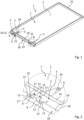
- All figures show at least parts of a plate element, designated 1 as a whole, for cladding a ceiling and/or wall.
- the plate element 1 has a rectangular cover plate 2 and several retaining springs 3.
- the retaining springs 3 are so-called leg springs, which are also referred to as torsion springs.
- the retaining springs 3 can, for example, be inserted into the Figures 1 to 4 shown transport positions are transferred to a fastening position in which some retaining springs 3 in the Figures 5 and 6 are shown.
- the retaining springs 3 are fastened to the cover plate 2 of the plate element 1 by means of a holding device 4.
- the Figures 1 to 4 illustrate that the holding device 4 is designed to fix the holding springs 3 in their respective transport position. In this way, the retaining springs 3 are securely fixed in their transport position on the cover plate 2 of the plate element 1.
- the holding device 4 is set up to fix the holding springs 3 in their respective transport position under tension.
- the Holding device 4 is designed so that the holding springs 3 are fixed in their transport position by their own spring force.
- the holding device 4 acts as a static support for tensioning the holding springs 3 in their transport position.
- the retaining springs 3 are aligned approximately parallel to the back 7 with their spring legs 5,6 in the transport position.
- the spring legs 5, 6 of the at least one retaining spring 3 are at a greater distance from one another in their fastening position than in their transport position. The retaining springs 3 are therefore more tensioned in the transport position than in the fastening position.
- the retaining springs 3 can be pivoted on the holding device 4.
- a pivot axis, around which the pivoting movement of the retaining springs 3 takes place, runs along the cover plate 2 of the plate element 1.
- the pivoting movement merely represents a movement component in order to transfer the retaining springs 3 from their transport position into their fastening position.
- the holding device 4 provides a combined longitudinal and pivoting guide for the holding springs 3.
- the retaining springs 3 are also arranged on the retaining device 4 so that they can be displaced along their longitudinal direction from their transport position.
- the holding device 4 limits a pivot angle of the holding springs 3 between their respective transport position and their respective fastening position to a maximum of 110 °.
- the pivot angle of the retaining springs 3 between their transport position and their fastening position is limited to 90 °.
- the holding device 4 has a holding opening 8 for each spring leg 5, 6 of the two holding springs 3.
- the two holding openings 8, which are assigned to a holding spring 3, have edges 9, 10 facing away from one another. According to the figures, these edges 9, 10 are aligned at right angles to the back 7 of the cover plate 2.
- the spring legs 5, 6 of the retaining springs 3 rest on these edges 9, 10 when the retaining spring 3 is in the transport position.
- the edges 9, 10 are at a distance from one another which is dimensioned such that the spring legs 5, 6 of the retaining springs 3 are kept tensioned when the retaining springs 3 are in the transport position.
- the retaining springs 3 are fixed in their transport position under tension.
- the tension for fixing the retaining springs 3 is generated by the respective retaining spring 3 itself through its own spring force.
- the spring legs 5,6 of the retaining springs 3 are hook-shaped at their free ends. With their hook-shaped ends, the retaining springs 3 can be hung on a holder 23, as is the case, for example, in the right half of figure 5 is shown. This makes assembly of the plate element 1 easier.
- the holding device 4 of the plate element 1 has insertion openings 11 adjacent to the holding openings 8.
- the insertion openings 11 each serve to accommodate a free, hook-shaped, curved end 12 of the spring legs 5,6 of the retaining springs 3.
- the hook-shaped ends 12 of the spring legs 5,6 positioned in the insertion openings 11 prevent the retaining springs 3 from being held by their spring force the spring legs 5,6 are pushed apart from their transport position along their longitudinal direction. This is possible particularly reliably if the hook-shaped ends 12 of the spring legs 5, 6 engage behind a respective edge of the insertion openings 11.
- the spring legs 5,6 can be bent between 100° and 200°, in particular by 180°.
- the holding openings 8 each comprise a first opening section 13 and a second opening section 14.
- the spring legs 5, 6 are placed in the first opening section 13 when the holding spring 3 is in the transport position and in the second opening section 14 of the holding openings 8 when the holding spring 3 is in the fastening position.
- the holding device 4 Between two holding openings 8 assigned to a holding spring 3, namely between two second opening sections 14, the holding device 4 each has a holding web 15. From the holding web 15, the holding springs 3, which are in the fastening position, are each fixed to the holding device 4 and thus to the cover plate 2 of the plate element 1 with an intermediate section 16 arranged between the spring legs 5, 6.
- the intermediate section 16 is from an eyelet which consists of turns of a wire from which the retaining springs 3 are each made.
- the respective first opening section 13 of the holding openings 8 is limited by an opening edge 17 in the pivoting direction of the holding springs 3 in the direction of their respective fastening position.
- the opening edge 17 is intended to secure the spring leg 5, 6 of the retaining spring 3, which is in the transport position in the first opening section 13, in a form-fitting manner in the direction of the fastening position of the retaining spring 3.
- the opening edge 17 is aligned parallel to the back 7 of the cover plate 2 of the plate element 1 in the plate element 1 shown in the figures.
- the first opening sections 13 of the holding openings 8 are arranged closer than the second opening sections 14 to the back 7 of the cover plate 2.
- the first opening section 13 of the holding opening 8 forms a larger angle with the back 7 of the cover plate 2 than the second opening section 14, which in the exemplary embodiment shown is aligned parallel to the back 7 of the cover plate 2.
- the angle here is 90°.
- the first opening section 13 and the second opening section 14 of the holding openings 8 are thus aligned at an angle of less than 180° to one another.
- the holding device 4 comprises a profile 18 which is arranged on an edge of the cover plate 2 and can therefore be referred to as an edge profile.
- the previously mentioned holding openings 8 are formed in the profile 18.
- the profile 18 includes a first profile leg 19, in which the first opening sections 13 of the holding device 8 are formed.
- the profile 18 also includes a second profile leg 20, in which the second opening sections 14 of the holding openings 8 are formed are.
- the profile 18 is formed by bending the cover plate 2 on the back 7 of the cover plate 2.
- a profile 18 is attached or formed on a side of the cover plate 2, which preferably does not represent a visible side 26 of the plate element 1.
- At least one holding device 4 with at least one holding spring 3 is arranged on two edges of the cover plate 2 facing away from one another.
- two retaining springs 3 are arranged on one edge of the cover plate 2.
- the cover plate 2 of the plate element 1 shown in the figures is made of metal. With its holding edge 21 facing away from the holding device 4, the cover plate 2 can be suspended in a correspondingly designed holding structure for fastening the ceiling element 1.
- the plate element 1 is held on the ceiling by the two retaining springs 3, while on the other side it can be at least indirectly attached to the ceiling or wall with the help of its retaining edge 21.
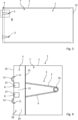
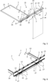
- the Figures 5 and 6 now show a cladding for a ceiling and/or wall, designated as a whole by 22.
- the fairing 22 includes several of the Figures 1 to 4 Plate elements 1 shown and at least one holder 23 attached to the ceiling and / or wall in the position of use.
- the plate elements 1 are in their position of use their retaining springs 3 are attached to the holder 23.
- the retaining springs 3 are suspended with their spring legs 5,6 in the holder 23.
- the holder 23 is designed as a holding profile and has several holding holes 24 in the form of elongated holes for hanging the spring legs 5,6.
- Figure 5 illustrates the assembly of the plate elements 1.
- the retaining springs 3 are pushed out from their respective transport position in the longitudinal direction.
- the retaining springs 3 are guided with the hook-shaped ends of their spring legs 5, 6 through the retaining holes 24 of the holder 23 and hooked into securing receptacles 27 of the holder 23 on both sides of the retaining holes 24 in order to hang up the plate element 1.
- the back 7 of the cover plate 3 is aligned approximately in or in the direction of gravity (see right half of Figure 5 ).
- the plate element 1 suspended in this way is then folded up by 90°, hooked with its holding edge 21 into a holding rail which is attached to the ceiling, and pushed towards the ceiling against the direction of gravity.
- the spring legs 5, 6 reach the second opening sections 14 of the holding openings 8. On the other hand, the spring legs 5, 6 continue to slide through the holding holes 24 and spread apart due to the spring force of the holding springs 3, whereby the plate element 1 can be properly hung.
- the plate elements 1 can come loose from their intended assembly position if strong vibrations and/or shocks act on them, for example during earthquakes. If the plate elements 1 unexpectedly come loose from their intended assembly position, the plate elements 1 can be removed using the hook-shaped ends 12 of the spring legs 5, 6 of their retaining springs 3 and the Safety recordings 27 can be caught and their fall prevented. If the plate elements 1 loosen, the spring legs 5, 6 slide through the retaining holes 24 until the hook-shaped ends 12 of the spring legs 5, 6 of the retaining springs 3 engage in the securing receptacles 27. The hook-shaped ends 12 remain there and secure the plate element 1 from falling.
- the plate element 1 has a stop in the form of a contact leg 25, with which it can rest against the holder 23 in the correct position of use.
- the contact leg 25 is a third profile leg of the profile 18 and is aligned at right angles to the back 7 of the cover plate 2 and/or at right angles to the second profile leg 20.
- the invention is concerned with improvements in the technical field of plate elements for cladding ceilings and/or walls.
- a plate element 1 which has a holding device 4 with which at least one retaining spring 3, which is used to fasten the plate element 1 to the ceiling and/or wall, can be fixed in its transport position.
Landscapes
- Engineering & Computer Science (AREA)
- Architecture (AREA)
- Civil Engineering (AREA)
- Structural Engineering (AREA)
- Physics & Mathematics (AREA)
- Electromagnetism (AREA)
- Clamps And Clips (AREA)
- Finishing Walls (AREA)
- Connection Of Plates (AREA)
- Vehicle Interior And Exterior Ornaments, Soundproofing, And Insulation (AREA)
- Building Environments (AREA)
Priority Applications (1)
| Application Number | Priority Date | Filing Date | Title |
|---|---|---|---|
| PL20728444.9T PL4127352T3 (pl) | 2020-05-20 | 2020-05-20 | Element płytowy do poszycia stropu i/lub ściany oraz poszycie stropu i/lub ściany |
Applications Claiming Priority (1)
| Application Number | Priority Date | Filing Date | Title |
|---|---|---|---|
| PCT/EP2020/064185 WO2021233544A1 (de) | 2020-05-20 | 2020-05-20 | Plattenelement zur verkleidung einer decke und/oder wand sowie verkleidung für eine decke und/oder wand |
Publications (3)
| Publication Number | Publication Date |
|---|---|
| EP4127352A1 EP4127352A1 (de) | 2023-02-08 |
| EP4127352B1 true EP4127352B1 (de) | 2024-01-31 |
| EP4127352C0 EP4127352C0 (de) | 2024-01-31 |
Family
ID=70857163
Family Applications (1)
| Application Number | Title | Priority Date | Filing Date |
|---|---|---|---|
| EP20728444.9A Active EP4127352B1 (de) | 2020-05-20 | 2020-05-20 | Plattenelement zur verkleidung einer decke und/oder wand sowie verkleidung für eine decke und/oder wand |
Country Status (8)
| Country | Link |
|---|---|
| US (1) | US12241254B2 (pl) |
| EP (1) | EP4127352B1 (pl) |
| AU (1) | AU2020448188A1 (pl) |
| CA (1) | CA3183662A1 (pl) |
| ES (1) | ES2978665T3 (pl) |
| MX (1) | MX2022014294A (pl) |
| PL (1) | PL4127352T3 (pl) |
| WO (1) | WO2021233544A1 (pl) |
Citations (2)
| Publication number | Priority date | Publication date | Assignee | Title |
|---|---|---|---|---|
| EP0744509A1 (en) * | 1995-05-12 | 1996-11-27 | Van Geel Systems B.V. | Suspension device for ceiling panels |
| DE202013000340U1 (de) * | 2013-01-14 | 2013-03-11 | Durlum Group Gmbh | Vorrichtung zum werkzeuglosen Öffnen von Deckenplatten |
Family Cites Families (24)
| Publication number | Priority date | Publication date | Assignee | Title |
|---|---|---|---|---|
| US3693303A (en) * | 1970-10-26 | 1972-09-26 | Donn Prod Inc | Removable grid member |
| US3784144A (en) * | 1972-08-09 | 1974-01-08 | Armstrong Cork Co | Ceiling system suspension clip |
| US4548010A (en) * | 1981-06-25 | 1985-10-22 | Decoustics Limited | Concealed suspended ceiling system |
| US4438613A (en) * | 1981-06-25 | 1984-03-27 | Decoustics Limited | Suspended ceiling panel system |
| US4408428A (en) * | 1982-09-28 | 1983-10-11 | United States Gypsum Company | Suspended panel ceiling having impact absorbent panel retaining clip assemblies |
| US5428930A (en) * | 1993-07-23 | 1995-07-04 | Decoustics Limited | Concealed grid ceiling panel system |
| US6971210B2 (en) * | 2002-12-19 | 2005-12-06 | Owens Corning Fiberglas Technology, Inc. | Accessible ceiling grid system |
| US20060157297A1 (en) * | 2005-01-14 | 2006-07-20 | Rpg Diffusor Systems, Inc. | Diverse acoustical modules with identical outward appearance |
| US20070193131A1 (en) * | 2006-02-21 | 2007-08-23 | Francisco Ortiz | Acoustical panel ceiling system |
| US7909297B1 (en) * | 2006-07-28 | 2011-03-22 | 3Form, Inc. | Flexible, low-profile hardware for mounting non-linear structures |
| CA2711332C (en) * | 2010-07-27 | 2016-09-13 | Decoustics Limited | Ceiling panel securing clip |
| US9194123B2 (en) * | 2014-04-29 | 2015-11-24 | Awi Licensing Company | Ceiling system |
| US9228347B2 (en) * | 2014-05-30 | 2016-01-05 | Usg Interiors, Llc | Torsion spring metal ceiling system and hardware |
| US9181696B1 (en) * | 2014-11-26 | 2015-11-10 | Awi Licensing Company | Assembly for supporting ceiling panels and ceiling system incorporating the same |
| US9187896B1 (en) * | 2014-11-26 | 2015-11-17 | Awi Licensing Company | Assembly for supporting ceiling panels and ceiling system incorporating the same |
| US9187897B1 (en) * | 2014-11-26 | 2015-11-17 | Awi Licensing Company | Assembly for supporting ceiling panels and ceiling system incorporating the same |
| US9435121B2 (en) * | 2014-11-26 | 2016-09-06 | Awi Licensing Llc | Assembly for supporting ceiling panels and ceiling system incorporating the same |
| EP3245347A1 (en) * | 2015-01-15 | 2017-11-22 | Rockwool International A/S | Ceiling panel for use with concealed grid system |
| US10113317B1 (en) * | 2015-04-16 | 2018-10-30 | Gordon Sales, Inc. | Apparatus and method for hanging architectural panels with concealed attachment points |
| JP7182169B2 (ja) * | 2019-02-28 | 2022-12-02 | パナソニックIpマネジメント株式会社 | 天井パネル |
| EP3744704A1 (en) * | 2019-05-29 | 2020-12-02 | Sika Technology Ag | Non-invasive repair and retrofitting of hardened cementitious materials |
| WO2021092000A1 (en) * | 2019-11-05 | 2021-05-14 | Armstrong World Industries, Inc. | Acoustical ceiling system |
| US11965342B2 (en) * | 2020-10-04 | 2024-04-23 | David John Simonsen | Wire mounting solutions |
| MX2024007072A (es) * | 2021-12-10 | 2024-08-22 | Armstrong World Ind Inc | Sistemas de techo. |
-
2020
- 2020-05-20 PL PL20728444.9T patent/PL4127352T3/pl unknown
- 2020-05-20 CA CA3183662A patent/CA3183662A1/en active Pending
- 2020-05-20 AU AU2020448188A patent/AU2020448188A1/en active Pending
- 2020-05-20 WO PCT/EP2020/064185 patent/WO2021233544A1/de not_active Ceased
- 2020-05-20 US US17/925,640 patent/US12241254B2/en active Active
- 2020-05-20 ES ES20728444T patent/ES2978665T3/es active Active
- 2020-05-20 EP EP20728444.9A patent/EP4127352B1/de active Active
- 2020-05-20 MX MX2022014294A patent/MX2022014294A/es unknown
Patent Citations (2)
| Publication number | Priority date | Publication date | Assignee | Title |
|---|---|---|---|---|
| EP0744509A1 (en) * | 1995-05-12 | 1996-11-27 | Van Geel Systems B.V. | Suspension device for ceiling panels |
| DE202013000340U1 (de) * | 2013-01-14 | 2013-03-11 | Durlum Group Gmbh | Vorrichtung zum werkzeuglosen Öffnen von Deckenplatten |
Also Published As
| Publication number | Publication date |
|---|---|
| PL4127352T3 (pl) | 2024-05-13 |
| US20230183984A1 (en) | 2023-06-15 |
| EP4127352A1 (de) | 2023-02-08 |
| MX2022014294A (es) | 2023-03-10 |
| ES2978665T3 (es) | 2024-09-17 |
| CA3183662A1 (en) | 2021-11-25 |
| WO2021233544A1 (de) | 2021-11-25 |
| EP4127352C0 (de) | 2024-01-31 |
| US12241254B2 (en) | 2025-03-04 |
| AU2020448188A1 (en) | 2023-01-05 |
Similar Documents
| Publication | Publication Date | Title |
|---|---|---|
| DE69308860T2 (de) | Vorrichtung zur befestigung von rohren an einer tragkonstruktion | |
| EP2592968B1 (de) | Verbindungseinrichtung und seitengitter zur fixierung einer auszugsführung an dem seitengitter | |
| DE29909715U1 (de) | Wellschlauch mit einer Halterung | |
| DE202010012567U1 (de) | Seilumlenkstück für einen Seilfensterheber | |
| DE102012209272A1 (de) | Befestigungsvorrichtung für Solarpaneele | |
| DE202007006094U1 (de) | Solarmodul-Anordnung mit Tragvorrichtung | |
| DE102017102643B4 (de) | Schubkasten und Verfahren zur Montage einer Rückwand an einer Seitenzarge eines Schubkastens | |
| DE202008010189U1 (de) | Auszugsvorrichtung für ein Haushaltsgerät | |
| EP2790549B1 (de) | Seitengitter | |
| DE102011056303A1 (de) | Befestigungselement und Seitengitter | |
| EP4127352B1 (de) | Plattenelement zur verkleidung einer decke und/oder wand sowie verkleidung für eine decke und/oder wand | |
| EP1965625B1 (de) | Varioträger | |
| DE102006033607A1 (de) | Einsteckelement für eine Schutzabdeckung | |
| DE60301931T2 (de) | Verbesserte Trageeinrichtung für Drahtgitterkanal mit Schnellkupplung | |
| EP2239390B1 (de) | Abhänger | |
| DE202010016136U1 (de) | Lattenträger | |
| DE202007008150U1 (de) | Befestigungsvorrichtung für Solarmodule | |
| DE102023103212B3 (de) | Halteelement zum Fixieren der Kabel einer Photovoltaikanlage | |
| DE3929557C2 (pl) | ||
| DE19726181C1 (de) | Federnde Halterung für Bremsbacken | |
| DE102019102776A1 (de) | Transportankersystem mit Schrägzugbewehrung | |
| EP4215250A1 (de) | Haken für seilringe an einem trampolin | |
| DE202016106355U1 (de) | Haltearm einer Wundspreizvorrichtung | |
| DE202024105180U1 (de) | Insektenschutz-Rahmensystem sowie Befestigungsfeder | |
| DE202017102320U1 (de) | Kabelhalter |
Legal Events
| Date | Code | Title | Description |
|---|---|---|---|
| STAA | Information on the status of an ep patent application or granted ep patent |
Free format text: STATUS: UNKNOWN |
|
| STAA | Information on the status of an ep patent application or granted ep patent |
Free format text: STATUS: THE INTERNATIONAL PUBLICATION HAS BEEN MADE |
|
| PUAI | Public reference made under article 153(3) epc to a published international application that has entered the european phase |
Free format text: ORIGINAL CODE: 0009012 |
|
| STAA | Information on the status of an ep patent application or granted ep patent |
Free format text: STATUS: REQUEST FOR EXAMINATION WAS MADE |
|
| 17P | Request for examination filed |
Effective date: 20221027 |
|
| AK | Designated contracting states |
Kind code of ref document: A1 Designated state(s): AL AT BE BG CH CY CZ DE DK EE ES FI FR GB GR HR HU IE IS IT LI LT LU LV MC MK MT NL NO PL PT RO RS SE SI SK SM TR |
|
| DAV | Request for validation of the european patent (deleted) | ||
| DAX | Request for extension of the european patent (deleted) | ||
| GRAP | Despatch of communication of intention to grant a patent |
Free format text: ORIGINAL CODE: EPIDOSNIGR1 |
|
| STAA | Information on the status of an ep patent application or granted ep patent |
Free format text: STATUS: GRANT OF PATENT IS INTENDED |
|
| INTG | Intention to grant announced |
Effective date: 20231009 |
|
| GRAS | Grant fee paid |
Free format text: ORIGINAL CODE: EPIDOSNIGR3 |
|
| GRAA | (expected) grant |
Free format text: ORIGINAL CODE: 0009210 |
|
| STAA | Information on the status of an ep patent application or granted ep patent |
Free format text: STATUS: THE PATENT HAS BEEN GRANTED |
|
| AK | Designated contracting states |
Kind code of ref document: B1 Designated state(s): AL AT BE BG CH CY CZ DE DK EE ES FI FR GB GR HR HU IE IS IT LI LT LU LV MC MK MT NL NO PL PT RO RS SE SI SK SM TR |
|
| REG | Reference to a national code |
Ref country code: GB Ref legal event code: FG4D Free format text: NOT ENGLISH Ref country code: CH Ref legal event code: EP |
|
| REG | Reference to a national code |
Ref country code: DE Ref legal event code: R096 Ref document number: 502020006876 Country of ref document: DE |
|
| REG | Reference to a national code |
Ref country code: IE Ref legal event code: FG4D Free format text: LANGUAGE OF EP DOCUMENT: GERMAN |
|
| U01 | Request for unitary effect filed |
Effective date: 20240226 |
|
| U07 | Unitary effect registered |
Designated state(s): AT BE BG DE DK EE FI FR IT LT LU LV MT NL PT SE SI Effective date: 20240304 |
|
| U20 | Renewal fee for the european patent with unitary effect paid |
Year of fee payment: 5 Effective date: 20240327 |
|
| REG | Reference to a national code |
Ref country code: LT Ref legal event code: MG9D |
|
| PG25 | Lapsed in a contracting state [announced via postgrant information from national office to epo] |
Ref country code: IS Free format text: LAPSE BECAUSE OF FAILURE TO SUBMIT A TRANSLATION OF THE DESCRIPTION OR TO PAY THE FEE WITHIN THE PRESCRIBED TIME-LIMIT Effective date: 20240531 |
|
| PG25 | Lapsed in a contracting state [announced via postgrant information from national office to epo] |
Ref country code: GR Free format text: LAPSE BECAUSE OF FAILURE TO SUBMIT A TRANSLATION OF THE DESCRIPTION OR TO PAY THE FEE WITHIN THE PRESCRIBED TIME-LIMIT Effective date: 20240501 |
|
| PG25 | Lapsed in a contracting state [announced via postgrant information from national office to epo] |
Ref country code: RS Free format text: LAPSE BECAUSE OF FAILURE TO SUBMIT A TRANSLATION OF THE DESCRIPTION OR TO PAY THE FEE WITHIN THE PRESCRIBED TIME-LIMIT Effective date: 20240430 Ref country code: HR Free format text: LAPSE BECAUSE OF FAILURE TO SUBMIT A TRANSLATION OF THE DESCRIPTION OR TO PAY THE FEE WITHIN THE PRESCRIBED TIME-LIMIT Effective date: 20240131 |
|
| PG25 | Lapsed in a contracting state [announced via postgrant information from national office to epo] |
Ref country code: RS Free format text: LAPSE BECAUSE OF FAILURE TO SUBMIT A TRANSLATION OF THE DESCRIPTION OR TO PAY THE FEE WITHIN THE PRESCRIBED TIME-LIMIT Effective date: 20240430 Ref country code: NO Free format text: LAPSE BECAUSE OF FAILURE TO SUBMIT A TRANSLATION OF THE DESCRIPTION OR TO PAY THE FEE WITHIN THE PRESCRIBED TIME-LIMIT Effective date: 20240430 Ref country code: IS Free format text: LAPSE BECAUSE OF FAILURE TO SUBMIT A TRANSLATION OF THE DESCRIPTION OR TO PAY THE FEE WITHIN THE PRESCRIBED TIME-LIMIT Effective date: 20240531 Ref country code: HR Free format text: LAPSE BECAUSE OF FAILURE TO SUBMIT A TRANSLATION OF THE DESCRIPTION OR TO PAY THE FEE WITHIN THE PRESCRIBED TIME-LIMIT Effective date: 20240131 Ref country code: GR Free format text: LAPSE BECAUSE OF FAILURE TO SUBMIT A TRANSLATION OF THE DESCRIPTION OR TO PAY THE FEE WITHIN THE PRESCRIBED TIME-LIMIT Effective date: 20240501 |
|
| REG | Reference to a national code |
Ref country code: ES Ref legal event code: FG2A Ref document number: 2978665 Country of ref document: ES Kind code of ref document: T3 Effective date: 20240917 |
|
| PG25 | Lapsed in a contracting state [announced via postgrant information from national office to epo] |
Ref country code: SM Free format text: LAPSE BECAUSE OF FAILURE TO SUBMIT A TRANSLATION OF THE DESCRIPTION OR TO PAY THE FEE WITHIN THE PRESCRIBED TIME-LIMIT Effective date: 20240131 |
|
| PG25 | Lapsed in a contracting state [announced via postgrant information from national office to epo] |
Ref country code: CZ Free format text: LAPSE BECAUSE OF FAILURE TO SUBMIT A TRANSLATION OF THE DESCRIPTION OR TO PAY THE FEE WITHIN THE PRESCRIBED TIME-LIMIT Effective date: 20240131 |
|
| PG25 | Lapsed in a contracting state [announced via postgrant information from national office to epo] |
Ref country code: SK Free format text: LAPSE BECAUSE OF FAILURE TO SUBMIT A TRANSLATION OF THE DESCRIPTION OR TO PAY THE FEE WITHIN THE PRESCRIBED TIME-LIMIT Effective date: 20240131 |
|
| PG25 | Lapsed in a contracting state [announced via postgrant information from national office to epo] |
Ref country code: SM Free format text: LAPSE BECAUSE OF FAILURE TO SUBMIT A TRANSLATION OF THE DESCRIPTION OR TO PAY THE FEE WITHIN THE PRESCRIBED TIME-LIMIT Effective date: 20240131 Ref country code: SK Free format text: LAPSE BECAUSE OF FAILURE TO SUBMIT A TRANSLATION OF THE DESCRIPTION OR TO PAY THE FEE WITHIN THE PRESCRIBED TIME-LIMIT Effective date: 20240131 Ref country code: RO Free format text: LAPSE BECAUSE OF FAILURE TO SUBMIT A TRANSLATION OF THE DESCRIPTION OR TO PAY THE FEE WITHIN THE PRESCRIBED TIME-LIMIT Effective date: 20240131 Ref country code: CZ Free format text: LAPSE BECAUSE OF FAILURE TO SUBMIT A TRANSLATION OF THE DESCRIPTION OR TO PAY THE FEE WITHIN THE PRESCRIBED TIME-LIMIT Effective date: 20240131 |
|
| REG | Reference to a national code |
Ref country code: DE Ref legal event code: R097 Ref document number: 502020006876 Country of ref document: DE |
|
| PLBE | No opposition filed within time limit |
Free format text: ORIGINAL CODE: 0009261 |
|
| STAA | Information on the status of an ep patent application or granted ep patent |
Free format text: STATUS: NO OPPOSITION FILED WITHIN TIME LIMIT |
|
| 26N | No opposition filed |
Effective date: 20241101 |
|
| PG25 | Lapsed in a contracting state [announced via postgrant information from national office to epo] |
Ref country code: MC Free format text: LAPSE BECAUSE OF FAILURE TO SUBMIT A TRANSLATION OF THE DESCRIPTION OR TO PAY THE FEE WITHIN THE PRESCRIBED TIME-LIMIT Effective date: 20240131 |
|
| GBPC | Gb: european patent ceased through non-payment of renewal fee |
Effective date: 20240520 |
|
| PG25 | Lapsed in a contracting state [announced via postgrant information from national office to epo] |
Ref country code: MC Free format text: LAPSE BECAUSE OF FAILURE TO SUBMIT A TRANSLATION OF THE DESCRIPTION OR TO PAY THE FEE WITHIN THE PRESCRIBED TIME-LIMIT Effective date: 20240131 |
|
| PG25 | Lapsed in a contracting state [announced via postgrant information from national office to epo] |
Ref country code: IE Free format text: LAPSE BECAUSE OF NON-PAYMENT OF DUE FEES Effective date: 20240520 |
|
| PG25 | Lapsed in a contracting state [announced via postgrant information from national office to epo] |
Ref country code: GB Free format text: LAPSE BECAUSE OF NON-PAYMENT OF DUE FEES Effective date: 20240520 |
|
| U20 | Renewal fee for the european patent with unitary effect paid |
Year of fee payment: 6 Effective date: 20250327 |
|
| PGFP | Annual fee paid to national office [announced via postgrant information from national office to epo] |
Ref country code: PL Payment date: 20250512 Year of fee payment: 6 |
|
| PGFP | Annual fee paid to national office [announced via postgrant information from national office to epo] |
Ref country code: ES Payment date: 20250616 Year of fee payment: 6 |
|
| PGFP | Annual fee paid to national office [announced via postgrant information from national office to epo] |
Ref country code: CH Payment date: 20250601 Year of fee payment: 6 |
|
| PGFP | Annual fee paid to national office [announced via postgrant information from national office to epo] |
Ref country code: TR Payment date: 20250514 Year of fee payment: 6 |
|
| PG25 | Lapsed in a contracting state [announced via postgrant information from national office to epo] |
Ref country code: CY Free format text: LAPSE BECAUSE OF FAILURE TO SUBMIT A TRANSLATION OF THE DESCRIPTION OR TO PAY THE FEE WITHIN THE PRESCRIBED TIME-LIMIT; INVALID AB INITIO Effective date: 20200520 |
|
| PG25 | Lapsed in a contracting state [announced via postgrant information from national office to epo] |
Ref country code: HU Free format text: LAPSE BECAUSE OF FAILURE TO SUBMIT A TRANSLATION OF THE DESCRIPTION OR TO PAY THE FEE WITHIN THE PRESCRIBED TIME-LIMIT; INVALID AB INITIO Effective date: 20200520 |