EP0744509A1 - Suspension device for ceiling panels - Google Patents
Suspension device for ceiling panels Download PDFInfo
- Publication number
- EP0744509A1 EP0744509A1 EP96201288A EP96201288A EP0744509A1 EP 0744509 A1 EP0744509 A1 EP 0744509A1 EP 96201288 A EP96201288 A EP 96201288A EP 96201288 A EP96201288 A EP 96201288A EP 0744509 A1 EP0744509 A1 EP 0744509A1
- Authority
- EP
- European Patent Office
- Prior art keywords
- panel
- pin
- standing wall
- frame
- corner
- Prior art date
- Legal status (The legal status is an assumption and is not a legal conclusion. Google has not performed a legal analysis and makes no representation as to the accuracy of the status listed.)
- Granted
Links
Images


Classifications
-
- E—FIXED CONSTRUCTIONS
- E04—BUILDING
- E04B—GENERAL BUILDING CONSTRUCTIONS; WALLS, e.g. PARTITIONS; ROOFS; FLOORS; CEILINGS; INSULATION OR OTHER PROTECTION OF BUILDINGS
- E04B9/00—Ceilings; Construction of ceilings, e.g. false ceilings; Ceiling construction with regard to insulation
- E04B9/003—Ceilings; Construction of ceilings, e.g. false ceilings; Ceiling construction with regard to insulation with movable parts, e.g. pivoting panels, access doors
-
- E—FIXED CONSTRUCTIONS
- E04—BUILDING
- E04B—GENERAL BUILDING CONSTRUCTIONS; WALLS, e.g. PARTITIONS; ROOFS; FLOORS; CEILINGS; INSULATION OR OTHER PROTECTION OF BUILDINGS
- E04B9/00—Ceilings; Construction of ceilings, e.g. false ceilings; Ceiling construction with regard to insulation
- E04B9/30—Ceilings; Construction of ceilings, e.g. false ceilings; Ceiling construction with regard to insulation characterised by edge details of the ceiling; e.g. securing to an adjacent wall
Definitions
- the sub-frame as pivoting support provided with a fixed pin-like member or as lock, in which case a movable pin-like member is arranged.
- the space R is embodied with a ceiling P, which ceiling consists of a plurality of panel-like ceiling elements 1 in mutually adjacent arrangement. These elements are suspended in a suspension frame 2, consisting here for instance of angle beams, which can be arranged in the space R in random manner.
- a suspension frame 2 consisting here for instance of angle beams, which can be arranged in the space R in random manner.
- Such ceiling panels 1 must not only be capable of easy fitting in suspension frame 2 but must also be releasable in order to enable replacement of the elements or to make the space above the ceiling panels accessible, for instance for work on conduits and the like.
- the panel-like ceiling element comprises a flat body part having in the embodiment shown a rectangular peripheral form, along which periphery standing wall parts 4 are arranged to form a cassette-like panel.
- Fig. 2 shows that the standing wall parts 4 are provided on the edge remote from body plate 3 with an inward bent flange 5, 6, wherein flange 6 has recesses 7 for the purpose of forming bending lips 8.
- Mounting of the fixed bolt 11 takes place by sliding the sub-frame into the corner of the panel-like element such that the hole 15 is in register with the hole 9 in standing wall 4.
- the slidable pins 21 can be mounted as according to fig. 4 on the two remaining corners of the panel-like ceiling element.
- the sub-frame consisting of support plates 12, 13 and 14 is once again placed in the corner, wherein however the pin 21 is placed in advance through holes 15, round which pin a pressure spring 22 is arranged, see fig. 5b.
- Mounted simultaneously with pin 21 is a lever 23 consisting of an L-shaped strip, the short leg of which is embodied with protrusions 24, which are received in the holes 19 of the sub-frame, and a lip 25 which can be placed through hole 10.
- 5b further shows that fitting of lever 23 takes place by bending the lower portion of support plate 12 respectively 13, depending on the left-hand or right-hand embodiment, see fig. 5b and c.
- the lip 25 protrudes through the hole 10 of the standing wall parts 4 so that it is accessible from outside.
- the sub-frame with arranged pin and lever as according to fig. 5b and c is fixed in the same manner in the corners of a ceiling panel using the bending lip.
- an auxiliary tool for instance a pressing plate 30 in fig. 1b, 1c, to cause the lever 23 to tilt on the tilt axis through the holes 19.
- the strip 23 which fits into a recess 26 of pin 21 presses the pin inward counter to the action of pressure spring 22.
- the ceiling panel can thus be placed flush with the angle profiles 2 and, by releasing the lip 25, the pressure spring 22 will push back pin 21 into a recess prearranged in the angle profiles 2. In this manner the ceiling panel is fixed.
- the ceiling panel can also be swung aside again by carrying out the reverse operation, which is shown in fig. 1e and f.
Landscapes
- Engineering & Computer Science (AREA)
- Architecture (AREA)
- Physics & Mathematics (AREA)
- Electromagnetism (AREA)
- Civil Engineering (AREA)
- Structural Engineering (AREA)
- Residential Or Office Buildings (AREA)
- Finishing Walls (AREA)
- Paper (AREA)
- Vehicle Interior And Exterior Ornaments, Soundproofing, And Insulation (AREA)
- Load-Engaging Elements For Cranes (AREA)
- Conveying And Assembling Of Building Elements In Situ (AREA)
Abstract
Description
- The invention relates to a device for suspending ceiling panels, which panel at least consists of a body plate having standing wall parts which are arranged at least in the corner thereof and which enclose a mutual angle, wherein the panel is suspended in a support frame using suspension means.
- Many suspension devices for ceiling panels are already known, which however all have the drawback of a construction which is complicated and thereby difficult to manufacture.
- The invention has for its object to improve the suspension device for panel-like ceiling elements such that it is necessary to work with only a minimum number of different components to suspend the element, but such that the element can be released and swung aside.
- The device according to the invention is distinguished in that the suspension means consist of a pin-like member which is carried through two plate-like supports for placing at a mutual distance in the corner and which protrudes beyond the standing wall part of the panel.
- In a further development the two plate-like supports are fixed to each other to form a U-shaped sub-frame. This sub-frame can be placed by means of simple fastening members in the corner portion of the panel in both a "left-hand" and "right-hand" embodiment.
- It is hereby possible to use the sub-frame as pivoting support provided with a fixed pin-like member or as lock, in which case a movable pin-like member is arranged.
- Above mentioned and other features of the invention will be further elucidated in the figure description hereinbelow of an embodiment. In the drawing:
- fig. 1a-f show in each case a perspective bottom view of a ceiling in a random space, which ceiling is embodied with panel-like ceiling elements,
- fig. 2 shows a perspective view of a detail of the corner of the panel-like ceiling element of fig. 1,
- fig. 3a, b show a perspective view corresponding with fig. 2 of the corner part of the ceiling element provided with a sub-frame with fixed pin-like member,
- fig. 4 shows a perspective view corresponding with fig. 2 provided with a pin-like member movable in axial sense as a lock,
- fig. 5a, b and c show a perspective view of the locking system of fig. 4 in dismantled state and as a left-hand mounted and right-hand mounted pin-like member.
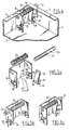
- In fig. 1 the space R is embodied with a ceiling P, which ceiling consists of a plurality of panel-
like ceiling elements 1 in mutually adjacent arrangement. These elements are suspended in a suspension frame 2, consisting here for instance of angle beams, which can be arranged in the space R in random manner.Such ceiling panels 1 must not only be capable of easy fitting in suspension frame 2 but must also be releasable in order to enable replacement of the elements or to make the space above the ceiling panels accessible, for instance for work on conduits and the like. - The panel-like ceiling element comprises a flat body part having in the embodiment shown a rectangular peripheral form, along which periphery standing
wall parts 4 are arranged to form a cassette-like panel. - The standing
wall parts 4 enclose at the corners an angle of 90° but it will be apparent that with a different peripheral form other angle settings can be realized. - The right angle between the standing
wall parts 4 is shown in detail in fig. 2-4. - Fig. 2 shows that the standing
wall parts 4 are provided on the edge remote frombody plate 3 with aninward bent flange 5, 6, wherein flange 6 has recesses 7 for the purpose of formingbending lips 8. - In the standing
wall part 4 not provided withbending lips 8 are arranged respective openings 9 and 10, the function of which is further elucidated below. - In order to enable suspension of the
ceiling elements 1, suspension means in the form of a fixed pin, see fig. 3a, 3b, or a slidable pin, see fig. 4, 5, are arranged in the corners. - Fig. 3a and 3b show that a fixed pin in the form of a bolt can be carried through the hole 9 and through two
support plates support plates plate 14 such that a U-shaped sub-frame is formed. Eachplate hole 15 which coincides with the hole in the standingwall 4 placed in the sub-frame in the corner. - Each
support plate holes 16 corresponding with the holes 10 in fig. 2 in addition toincisions 17 respectively 18 arranged close to theseholes 16, and ahole 19. - Mounting of the fixed
bolt 11 takes place by sliding the sub-frame into the corner of the panel-like element such that thehole 15 is in register with the hole 9 in standingwall 4. - The
bending lip 8 is folded inward against the inside ofplate 14, whereby the sub-frame is fixed into the corner. Thebolt 8 is subsequently fastened to the left-hand support plate 13 in fig. 3b by means of twonuts 20. The bolt head ofbolt 11 protrudes some distance on the outside of the standingwall 4, see fig. 3b, whereby this bolt head can be fixed to the sub-frame 2 in fig. 1. The bolt head can for instance be hung in a recess of angle profile 2 opening toward the top. Alternatively, a circular hole can be arranged in the angle profile 2 through which the bolt must first be placed prior to being fixed to the sub-frame in the panel-like element. - It will be apparent that two
bolts 11 are arranged mutually in line at either end of the rear standingwall part 4 in order to form a pivot axis. Theslidable pins 21 can be mounted as according to fig. 4 on the two remaining corners of the panel-like ceiling element. The sub-frame consisting ofsupport plates pin 21 is placed in advance throughholes 15, round which pin apressure spring 22 is arranged, see fig. 5b. Mounted simultaneously withpin 21 is alever 23 consisting of an L-shaped strip, the short leg of which is embodied withprotrusions 24, which are received in theholes 19 of the sub-frame, and alip 25 which can be placed through hole 10. Fig. 5b further shows that fitting oflever 23 takes place by bending the lower portion ofsupport plate 12 respectively 13, depending on the left-hand or right-hand embodiment, see fig. 5b and c. Thelip 25 protrudes through the hole 10 of the standingwall parts 4 so that it is accessible from outside. - The sub-frame with arranged pin and lever as according to fig. 5b and c is fixed in the same manner in the corners of a ceiling panel using the bending lip. For fitting of the ceiling panel it is only necessary to press against the
lip 25 with an auxiliary tool, for instance apressing plate 30 in fig. 1b, 1c, to cause thelever 23 to tilt on the tilt axis through theholes 19. Thestrip 23 which fits into arecess 26 ofpin 21 presses the pin inward counter to the action ofpressure spring 22. The ceiling panel can thus be placed flush with the angle profiles 2 and, by releasing thelip 25, thepressure spring 22 will push backpin 21 into a recess prearranged in the angle profiles 2. In this manner the ceiling panel is fixed. The ceiling panel can also be swung aside again by carrying out the reverse operation, which is shown in fig. 1e and f. - The invention is not limited to the above described embodiments.
Claims (6)
- Device for suspending ceiling panels, which panel at least consists of a body plate having standing wall parts which are arranged at least in the corner thereof and which enclose a mutual angle, wherein the panel is suspended in a support frame using suspension means, characterized in that the suspension means consist of a pin-like member which is carried through two plate-like supports for placing at a mutual distance in the corner and which protrudes beyond the standing wall part of the panel.
- Device as claimed in claim 1, characterized in that the supports are the legs of a U-shaped sub-frame.
- Device as claimed in claim 2, characterized in that the pin-like body is received slidably in the legs and is biased by a tensioning member.
- Device as claimed in claim 3, characterized in that the legs are provided with holes to support and allow passage of a control lever which engages the pin-like body.
- Device as claimed in claim 2, characterized in that the legs have local incisions to obtain bending lips.
- Device as claimed in claims 1 and 2, characterized in that the standing wall part is provided with a bent flange which is interrupted locally to form one or more bending lips for fixing of the sub-frame.
Applications Claiming Priority (2)
| Application Number | Priority Date | Filing Date | Title |
|---|---|---|---|
| NL1000356A NL1000356C2 (en) | 1995-05-12 | 1995-05-12 | Suspension device for ceiling tiles. |
| NL1000356 | 1995-05-12 |
Publications (2)
| Publication Number | Publication Date |
|---|---|
| EP0744509A1 true EP0744509A1 (en) | 1996-11-27 |
| EP0744509B1 EP0744509B1 (en) | 2002-09-18 |
Family
ID=19761023
Family Applications (1)
| Application Number | Title | Priority Date | Filing Date |
|---|---|---|---|
| EP96201288A Expired - Lifetime EP0744509B1 (en) | 1995-05-12 | 1996-05-10 | Suspension device for ceiling panels |
Country Status (5)
| Country | Link |
|---|---|
| EP (1) | EP0744509B1 (en) |
| AT (1) | ATE224490T1 (en) |
| DE (1) | DE69623686D1 (en) |
| DK (1) | DK0744509T3 (en) |
| NL (1) | NL1000356C2 (en) |
Cited By (2)
| Publication number | Priority date | Publication date | Assignee | Title |
|---|---|---|---|---|
| GB2393975A (en) * | 2002-10-11 | 2004-04-14 | Simon Jonathan Crabtree | Access panel |
| EP4127352B1 (en) * | 2020-05-20 | 2024-01-31 | durlum Group GmbH | Panel element for cladding a ceiling and / or wall and cladding for a ceiling and / or wall |
Citations (4)
| Publication number | Priority date | Publication date | Assignee | Title |
|---|---|---|---|---|
| AU2493871A (en) * | 1971-02-02 | 1972-08-10 | Hermes Engineering Pty. Limited | Ceiling panel support arrangements |
| DE9004023U1 (en) * | 1990-04-06 | 1990-06-21 | DIG Deutsche Innenbau GmbH, 4330 Mülheim | Kit for a coffered ceiling |
| EP0589115A1 (en) * | 1992-08-27 | 1994-03-30 | Clestra Hauserman, S.A. | Ceiling |
| EP0616094A1 (en) * | 1993-03-18 | 1994-09-21 | Wilhelmi Werke GmbH & Co. KG | Ceiling tray panel |
-
1995
- 1995-05-12 NL NL1000356A patent/NL1000356C2/en not_active IP Right Cessation
-
1996
- 1996-05-10 DE DE69623686T patent/DE69623686D1/en not_active Expired - Lifetime
- 1996-05-10 DK DK96201288T patent/DK0744509T3/en active
- 1996-05-10 AT AT96201288T patent/ATE224490T1/en not_active IP Right Cessation
- 1996-05-10 EP EP96201288A patent/EP0744509B1/en not_active Expired - Lifetime
Patent Citations (4)
| Publication number | Priority date | Publication date | Assignee | Title |
|---|---|---|---|---|
| AU2493871A (en) * | 1971-02-02 | 1972-08-10 | Hermes Engineering Pty. Limited | Ceiling panel support arrangements |
| DE9004023U1 (en) * | 1990-04-06 | 1990-06-21 | DIG Deutsche Innenbau GmbH, 4330 Mülheim | Kit for a coffered ceiling |
| EP0589115A1 (en) * | 1992-08-27 | 1994-03-30 | Clestra Hauserman, S.A. | Ceiling |
| EP0616094A1 (en) * | 1993-03-18 | 1994-09-21 | Wilhelmi Werke GmbH & Co. KG | Ceiling tray panel |
Cited By (3)
| Publication number | Priority date | Publication date | Assignee | Title |
|---|---|---|---|---|
| GB2393975A (en) * | 2002-10-11 | 2004-04-14 | Simon Jonathan Crabtree | Access panel |
| GB2393975B (en) * | 2002-10-11 | 2005-12-07 | Simon Jonathan Crabtree | An access panel |
| EP4127352B1 (en) * | 2020-05-20 | 2024-01-31 | durlum Group GmbH | Panel element for cladding a ceiling and / or wall and cladding for a ceiling and / or wall |
Also Published As
| Publication number | Publication date |
|---|---|
| DK0744509T3 (en) | 2002-10-14 |
| ATE224490T1 (en) | 2002-10-15 |
| DE69623686D1 (en) | 2002-10-24 |
| EP0744509B1 (en) | 2002-09-18 |
| NL1000356C2 (en) | 1996-11-13 |
Similar Documents
| Publication | Publication Date | Title |
|---|---|---|
| US5394668A (en) | Panel extension assembly | |
| EP0443202B1 (en) | Work space management system hallway wall arrangement | |
| US5809714A (en) | Cabinet structure | |
| GB2407121A (en) | Glass fixing grommet | |
| US5836112A (en) | Partition system including transaction top | |
| EP0744509A1 (en) | Suspension device for ceiling panels | |
| NL7906395A (en) | CORNER JOINT FOR PLATES. | |
| EP1898016B1 (en) | Suspended ceiling with downwardly pivotable panels | |
| JPH0740004Y2 (en) | Locking device for wall panel etc. to the column | |
| US5076177A (en) | Simply-constructed detachable display shelf | |
| US5303892A (en) | Panel for recessed mounting of a housing | |
| CA2296703A1 (en) | Improvements relating to connection devices | |
| JP2005102739A (en) | Desk panel device | |
| JP4584477B2 (en) | Table with panel | |
| JP3463731B2 (en) | table | |
| JP2595345Y2 (en) | Ceiling panel mounting structure | |
| JPH0421476Y2 (en) | ||
| JPH082256Y2 (en) | Partition wall structure of sanitary equipment room | |
| CA2149582A1 (en) | Bedroom Door Brace Security System | |
| JPH0732681Y2 (en) | Base panel assembly structure for building panels | |
| JPH09243163A (en) | Fan coil storing device at perimeter section | |
| GB2240124A (en) | Support structure for ceiling members | |
| JP2695758B2 (en) | Ceiling panel mounting structure | |
| JP2843534B2 (en) | Decorative panel mounting structure and method of mounting partition storage furniture | |
| JP2003013521A (en) | Structure of wall, construction method, for wall, and elastic support mechanism |
Legal Events
| Date | Code | Title | Description |
|---|---|---|---|
| PUAI | Public reference made under article 153(3) epc to a published international application that has entered the european phase |
Free format text: ORIGINAL CODE: 0009012 |
|
| AK | Designated contracting states |
Kind code of ref document: A1 Designated state(s): AT BE CH DE DK ES FR GB LI LU NL PT |
|
| 17P | Request for examination filed |
Effective date: 19970512 |
|
| 17Q | First examination report despatched |
Effective date: 19990721 |
|
| RAP1 | Party data changed (applicant data changed or rights of an application transferred) |
Owner name: VAN GEEL METAL B.V. |
|
| GRAG | Despatch of communication of intention to grant |
Free format text: ORIGINAL CODE: EPIDOS AGRA |
|
| GRAG | Despatch of communication of intention to grant |
Free format text: ORIGINAL CODE: EPIDOS AGRA |
|
| GRAH | Despatch of communication of intention to grant a patent |
Free format text: ORIGINAL CODE: EPIDOS IGRA |
|
| GRAH | Despatch of communication of intention to grant a patent |
Free format text: ORIGINAL CODE: EPIDOS IGRA |
|
| GRAA | (expected) grant |
Free format text: ORIGINAL CODE: 0009210 |
|
| AK | Designated contracting states |
Kind code of ref document: B1 Designated state(s): AT BE CH DE DK ES FR GB LI LU NL PT |
|
| PG25 | Lapsed in a contracting state [announced via postgrant information from national office to epo] |
Ref country code: NL Free format text: LAPSE BECAUSE OF FAILURE TO SUBMIT A TRANSLATION OF THE DESCRIPTION OR TO PAY THE FEE WITHIN THE PRESCRIBED TIME-LIMIT Effective date: 20020918 Ref country code: FR Free format text: LAPSE BECAUSE OF NON-PAYMENT OF DUE FEES Effective date: 20020918 Ref country code: BE Free format text: LAPSE BECAUSE OF FAILURE TO SUBMIT A TRANSLATION OF THE DESCRIPTION OR TO PAY THE FEE WITHIN THE PRESCRIBED TIME-LIMIT Effective date: 20020918 |
|
| REF | Corresponds to: |
Ref document number: 224490 Country of ref document: AT Date of ref document: 20021015 Kind code of ref document: T |
|
| REG | Reference to a national code |
Ref country code: GB Ref legal event code: FG4D |
|
| REG | Reference to a national code |
Ref country code: CH Ref legal event code: EP |
|
| REG | Reference to a national code |
Ref country code: DK Ref legal event code: T3 |
|
| REF | Corresponds to: |
Ref document number: 69623686 Country of ref document: DE Date of ref document: 20021024 |
|
| PG25 | Lapsed in a contracting state [announced via postgrant information from national office to epo] |
Ref country code: PT Free format text: LAPSE BECAUSE OF FAILURE TO SUBMIT A TRANSLATION OF THE DESCRIPTION OR TO PAY THE FEE WITHIN THE PRESCRIBED TIME-LIMIT Effective date: 20021219 Ref country code: DE Free format text: LAPSE BECAUSE OF FAILURE TO SUBMIT A TRANSLATION OF THE DESCRIPTION OR TO PAY THE FEE WITHIN THE PRESCRIBED TIME-LIMIT Effective date: 20021219 |
|
| NLV1 | Nl: lapsed or annulled due to failure to fulfill the requirements of art. 29p and 29m of the patents act | ||
| PG25 | Lapsed in a contracting state [announced via postgrant information from national office to epo] |
Ref country code: ES Free format text: LAPSE BECAUSE OF FAILURE TO SUBMIT A TRANSLATION OF THE DESCRIPTION OR TO PAY THE FEE WITHIN THE PRESCRIBED TIME-LIMIT Effective date: 20030328 |
|
| PG25 | Lapsed in a contracting state [announced via postgrant information from national office to epo] |
Ref country code: LU Free format text: LAPSE BECAUSE OF NON-PAYMENT OF DUE FEES Effective date: 20030510 Ref country code: GB Free format text: LAPSE BECAUSE OF NON-PAYMENT OF DUE FEES Effective date: 20030510 Ref country code: AT Free format text: LAPSE BECAUSE OF NON-PAYMENT OF DUE FEES Effective date: 20030510 |
|
| PG25 | Lapsed in a contracting state [announced via postgrant information from national office to epo] |
Ref country code: LI Free format text: LAPSE BECAUSE OF NON-PAYMENT OF DUE FEES Effective date: 20030531 Ref country code: CH Free format text: LAPSE BECAUSE OF NON-PAYMENT OF DUE FEES Effective date: 20030531 |
|
| EN | Fr: translation not filed | ||
| PLBE | No opposition filed within time limit |
Free format text: ORIGINAL CODE: 0009261 |
|
| STAA | Information on the status of an ep patent application or granted ep patent |
Free format text: STATUS: NO OPPOSITION FILED WITHIN TIME LIMIT |
|
| 26N | No opposition filed |
Effective date: 20030619 |
|
| PG25 | Lapsed in a contracting state [announced via postgrant information from national office to epo] |
Ref country code: DK Free format text: LAPSE BECAUSE OF NON-PAYMENT OF DUE FEES Effective date: 20031201 |
|
| REG | Reference to a national code |
Ref country code: DK Ref legal event code: EBP |
|
| GBPC | Gb: european patent ceased through non-payment of renewal fee |
Effective date: 20030510 |
|
| REG | Reference to a national code |
Ref country code: CH Ref legal event code: PL |