EP4126476B1 - Roboterbohrklemme und computerimplementierte verfahren zum betrieb eines roboterbohrers - Google Patents
Roboterbohrklemme und computerimplementierte verfahren zum betrieb eines roboterbohrers Download PDFInfo
- Publication number
- EP4126476B1 EP4126476B1 EP21716822.8A EP21716822A EP4126476B1 EP 4126476 B1 EP4126476 B1 EP 4126476B1 EP 21716822 A EP21716822 A EP 21716822A EP 4126476 B1 EP4126476 B1 EP 4126476B1
- Authority
- EP
- European Patent Office
- Prior art keywords
- workpiece
- clamp
- drilling tool
- robotic
- drill
- Prior art date
- Legal status (The legal status is an assumption and is not a legal conclusion. Google has not performed a legal analysis and makes no representation as to the accuracy of the status listed.)
- Active
Links
Images


Classifications
-
- B—PERFORMING OPERATIONS; TRANSPORTING
- B25—HAND TOOLS; PORTABLE POWER-DRIVEN TOOLS; MANIPULATORS
- B25J—MANIPULATORS; CHAMBERS PROVIDED WITH MANIPULATION DEVICES
- B25J15/00—Gripping heads and other end effectors
- B25J15/02—Gripping heads and other end effectors servo-actuated
- B25J15/0253—Gripping heads and other end effectors servo-actuated comprising parallel grippers
-
- B—PERFORMING OPERATIONS; TRANSPORTING
- B23—MACHINE TOOLS; METAL-WORKING NOT OTHERWISE PROVIDED FOR
- B23B—TURNING; BORING
- B23B39/00—General-purpose boring or drilling machines or devices; Sets of boring and/or drilling machines
- B23B39/14—General-purpose boring or drilling machines or devices; Sets of boring and/or drilling machines with special provision to enable the machine or the drilling or boring head to be moved into any desired position, e.g. with respect to immovable work
-
- B—PERFORMING OPERATIONS; TRANSPORTING
- B23—MACHINE TOOLS; METAL-WORKING NOT OTHERWISE PROVIDED FOR
- B23B—TURNING; BORING
- B23B49/00—Measuring or gauging equipment on boring machines for positioning or guiding the drill; Devices for indicating failure of drills during boring; Centering devices for holes to be bored
- B23B49/003—Stops attached to drilling tools, tool holders or drilling machines
- B23B49/006—Attached to drilling machines
- B23B49/008—Attached to the nose of the drilling machines
-
- B—PERFORMING OPERATIONS; TRANSPORTING
- B25—HAND TOOLS; PORTABLE POWER-DRIVEN TOOLS; MANIPULATORS
- B25J—MANIPULATORS; CHAMBERS PROVIDED WITH MANIPULATION DEVICES
- B25J11/00—Manipulators not otherwise provided for
- B25J11/005—Manipulators for mechanical processing tasks
-
- B—PERFORMING OPERATIONS; TRANSPORTING
- B25—HAND TOOLS; PORTABLE POWER-DRIVEN TOOLS; MANIPULATORS
- B25J—MANIPULATORS; CHAMBERS PROVIDED WITH MANIPULATION DEVICES
- B25J11/00—Manipulators not otherwise provided for
- B25J11/005—Manipulators for mechanical processing tasks
- B25J11/0055—Cutting
-
- B—PERFORMING OPERATIONS; TRANSPORTING
- B25—HAND TOOLS; PORTABLE POWER-DRIVEN TOOLS; MANIPULATORS
- B25J—MANIPULATORS; CHAMBERS PROVIDED WITH MANIPULATION DEVICES
- B25J13/00—Controls for manipulators
- B25J13/08—Controls for manipulators by means of sensing devices, e.g. viewing or touching devices
- B25J13/085—Force or torque sensors
-
- B—PERFORMING OPERATIONS; TRANSPORTING
- B25—HAND TOOLS; PORTABLE POWER-DRIVEN TOOLS; MANIPULATORS
- B25J—MANIPULATORS; CHAMBERS PROVIDED WITH MANIPULATION DEVICES
- B25J13/00—Controls for manipulators
- B25J13/08—Controls for manipulators by means of sensing devices, e.g. viewing or touching devices
- B25J13/088—Controls for manipulators by means of sensing devices, e.g. viewing or touching devices with position, velocity or acceleration sensors
- B25J13/089—Determining the position of the robot with reference to its environment
-
- B—PERFORMING OPERATIONS; TRANSPORTING
- B25—HAND TOOLS; PORTABLE POWER-DRIVEN TOOLS; MANIPULATORS
- B25J—MANIPULATORS; CHAMBERS PROVIDED WITH MANIPULATION DEVICES
- B25J15/00—Gripping heads and other end effectors
- B25J15/0019—End effectors other than grippers
-
- B—PERFORMING OPERATIONS; TRANSPORTING
- B25—HAND TOOLS; PORTABLE POWER-DRIVEN TOOLS; MANIPULATORS
- B25J—MANIPULATORS; CHAMBERS PROVIDED WITH MANIPULATION DEVICES
- B25J15/00—Gripping heads and other end effectors
- B25J15/0095—Gripping heads and other end effectors with an external support, i.e. a support which does not belong to the manipulator or the object to be gripped, e.g. for maintaining the gripping head in an accurate position, guiding it or preventing vibrations
-
- B—PERFORMING OPERATIONS; TRANSPORTING
- B25—HAND TOOLS; PORTABLE POWER-DRIVEN TOOLS; MANIPULATORS
- B25J—MANIPULATORS; CHAMBERS PROVIDED WITH MANIPULATION DEVICES
- B25J9/00—Programme-controlled manipulators
- B25J9/16—Programme controls
- B25J9/1628—Programme controls characterised by the control loop
- B25J9/1633—Programme controls characterised by the control loop compliant, force, torque control, e.g. combined with position control
-
- B—PERFORMING OPERATIONS; TRANSPORTING
- B23—MACHINE TOOLS; METAL-WORKING NOT OTHERWISE PROVIDED FOR
- B23B—TURNING; BORING
- B23B2215/00—Details of workpieces
- B23B2215/04—Aircraft components
-
- B—PERFORMING OPERATIONS; TRANSPORTING
- B23—MACHINE TOOLS; METAL-WORKING NOT OTHERWISE PROVIDED FOR
- B23B—TURNING; BORING
- B23B2260/00—Details of constructional elements
- B23B2260/048—Devices to regulate the depth of cut
- B23B2260/0482—Depth controls, e.g. depth stops
-
- B—PERFORMING OPERATIONS; TRANSPORTING
- B23—MACHINE TOOLS; METAL-WORKING NOT OTHERWISE PROVIDED FOR
- B23B—TURNING; BORING
- B23B2260/00—Details of constructional elements
- B23B2260/128—Sensors
Definitions
- the invention relates to a clamp for a robotic drill, and to a related method and system for robotic drilling of a component.
- FIG. 1 illustrates the origin of three different types of possible errors in a robotic arm.
- Kinematic errors ( Figure 1a )) result in positional or rotational errors at each joint.
- Compliance and process forces ( Figure 1b )) result in errors arising from forces on the robotic arm that create displacement without necessarily resulting in any movement being measured.
- a clamp may be used to ensure that a drilling tool is held in position against a component to be machined.
- the clamp may be pneumatically actuated, applying a high pressure against the workpiece.
- the pressure can force the drill out of its intended position, leading to inaccurate positioning.
- such pressures may cause damage to the workpiece, which may not be evident if for example the workpiece is formed of a composite material.
- DE102017213717A1 discloses a machining device including the features of the preamble of present claim 1, for machining large-area, freely formed components on an aircraft, comprising a guide frame for guiding a tool spindle, a holding device for accommodating the tool spindle, wherein the guide frame is slidably mounted on the holding device via a linear bearing, a support element which can be connected or is connected to the guide frame for supporting the processing device on a surface of the component to be processed, an element for adjusting the contact pressure with which the processing device is pressed against the surface of the component, and a servo unit with which the guide frame relative to the holding device is displaceable.
- a method for machining large-area, free-form components is disclosed, comprising: positioning the machining device relative to the large-area, free-form component to be machined and pressing the machining device against the component with a contact pressure.
- US 2014/0348603 A1 discloses a drilling apparatus including: a drill rotatable about a center axis and capable of advancing and retracting along the axis; and a pressing unit for pressing a work in an advancing direction of the drill.
- the drilling apparatus advances the drill while rotating the drill about the center axis to form a hole in the work, in a state in which the work is pressed by the pressing unit.
- a pressing force applied on the work by the pressing unit is set to a predetermined pressing force based on machining reaction applied to the drill from the work during drilling and the pressing force causing deformation of the work in the advancing direction of the drill.
- the predetermined pressing force can suppress deformation of the work and displacement of the drill due to the machining reaction.
- the machining reaction and the pressing force are calculated beforehand in a drilling test.
- a clamp configured for attachment to a drilling tool of a robotic drill, the clamp comprising:
- An advantage is that the combination of a servo motor driven actuation mechanism with a force sensor enables a controlled clamping force to be applied to the workpiece to be machined, reducing or controlling positioning errors that may otherwise result.
- the workpiece contacting portion may have a non-slip surface for contacting the workpiece surface.
- the non-slip surface may for example comprise a rubber layer or coating.
- the rubber may for example be neoprene. Such a non-slip surface further reduces the possibility of the drilling tool moving out of position during a clamping operation.
- the arms and end piece may be of unitary construction.
- the frame having a C-shape prevents deflection, distortion and/or skidding of the frame when the surface of the workpiece contacting portion contacts the workpiece and a clamping force is applied.
- Rotation of the rods may be synchronised by a pulley or timing belt extending between the pair of arms. Synchronising rotation of the rods enables the frame to be actuated so that the force applied at the workpiece contacting portion is concentric with the drilling direction.
- a robotic drilling system comprising:
- the robotic drilling system may comprise a metrology system for measuring a position of the drilling tool relative to the workpiece to be machined.
- the metrology system may comprise a first plurality of datums located on the robotic drill and a second plurality of datums located on the workpiece holder.
- the controller may be configured to receive signals from the first and/or second plurality of datums to determine a position of the drilling tool relative to the workpiece.
- the metrology system may be an optical metrology system, and the first and second plurality of datums may comprise optical emitters.
- the metrology system may comprise a plurality of optical sensors arranged to determine a position of the tool relative to the workpiece holder based on signals received by the optical sensors from the first and second plurality of optical emitters.
- the controller may be configured to:
- the controller may be configured to determine and store a bias for a plurality of predetermined locations on the workpiece.
- the controller may be configured to:
- the controller may be configured to measure a position of the drilling tool after actuating the servo motor and to update the stored bias for the predetermined location.
- the system may thereby be continually updated during drilling operations to maintain positional accuracy.
- the use of the metrology system to determine a bias for each location on the workpiece to be machined allows an offset correction or bias to be made that is specific to each location, since different locations on a complex workpiece will result in different compliances coming into play on the robotic drill.
- the compliance will differ depending on the orientation of the arm relative to the workpiece holder.
- a computer-implemented method for operating a robotic drill comprising, in a first mode:
- the first mode of the method may be repeated for a plurality of predetermined locations on the workpiece.
- the method may further comprise, in a second mode:
- the second mode of the method may be repeated for the predetermined locations on the workpiece.
- a method for operating a robotic drill comprising:
- the method may be repeated for a plurality of predetermined locations on the workpiece.
- a computer program comprising instructions for causing a computerised controller to perform the method according to the third or fourth aspects.
- the computer program may be recorded on a non-transitory storage medium.
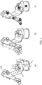
- Figures 1a), 1b) and 1c ) show a robotic arm 100, illustrating different sources of positional inaccuracy, as described in the background section above.
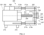
- FIG 2 is a schematic drawing of an example clamp 200 configured for attachment to a drilling tool 201 of a robotic drill, which may for example comprise a robotic arm of the type shown in Figure 1 .
- the clamp 200 comprises an attachment portion 220 for attachment to the drilling tool 201, and a frame 202 that is linearly moveable relative to the attachment portion 220 along a central axis 203 of the drilling tool 201, i.e. along a rotational axis of a drill bit 204 attached to the drilling tool 201.
- the drilling tool 201 is configured to drill a workpiece by actuating the drill bit 204 along the central axis 203 in the direction indicated by arrow 221.
- the clamp 200 comprises an actuation mechanism comprising a servo motor 205 configured to drive linear movement of the frame 202 relative to the attachment portion 220, i.e. relative to the drilling tool 201.
- a workpiece contacting portion 206 at a distal end 207 of the frame 202 comprises a surface 208 for contacting a surface of a workpiece to be drilled and an aperture 209 allowing for passage of the drill bit 204 through to the workpiece surface.
- a force sensor 210 is arranged to measure a force acting on the workpiece contacting portion 206 in the drilling direction.
- the force sensor 210 may for example form part of the workpiece contacting portion 206 or may be provided elsewhere in the frame 200 or attachment portion 220 to measure a force acting along the central axis 203 between the workpiece and the drilling tool 201.
- the workpiece contacting portion 206 may have a non-slip surface 208 for contacting the workpiece.
- the frame 202 in the example of Figure 2 generally has a C-shape, with a pair of arms 211a, 211b extending in the drilling direction on either side of the central axis 203 and a distal end piece 212 extending between the pair of arms 211a, 211b.
- the arms 211a, 211b and the distal end piece 212 may be of unitary construction, for example formed of a single piece of metal, to aid stiffness and prevent distortion of the frame 202 during use. Other shapes may also be possible, and the frame 202 may have more than two arms 211a, 211b.
- the servo motor 205 drives each of the arms 211a, 211b of the frame 202 by driving respective rods 213a, 213b extending along each arm 211a, 211b.
- a pulley or timing belt 214 extends between the pair of arms 211a, 211b across the distal end section 212, allowing for the rotation of the rods 213a, 213b to be synchronised so that the frame 202 moves in a uniform linear direction along the central axis 203, thereby applying a force on the workpiece parallel with the drilling direction.
- a plurality of datums 215 may be provided, which may be attached to the part of the clamp that is secured to the drilling tool 201, i.e. the attachment portion 220, to allow for a metrology system to determine a location of the drilling tool 201, described in further detail below.
- a metrology system to determine a location of the drilling tool 201, described in further detail below.
- at least three datums 215 will be required to enable a precise location and orientation in three-dimensional space to be determined.
- FIG 3 illustrates schematically an example robotic drilling system 300.
- the system 300 comprises a robotic drill 301 comprising a drilling tool 201, on to which a clamp 200 of the type described above is attached.
- a workpiece holder 302 is provided for holding a workpiece (not shown) to be machined.
- a controller 303 is connected to the robotic drill 301 for control of the robotic drill 301 and clamp 200.
- the controller 303 actuates the robotic drill 301 to contact the surface of the workpiece contacting portion 208 ( Figure 2 ) to the surface of a workpiece to be machined and actuates the servo motor 205 in the clamp 200 to drive the clamp 200 on to the workpiece while measuring a force from the force sensor 206 until a predetermined force has been reached.
- the controller 303 may then operate the drilling tool 201 to drill a hole into the workpiece.
- the system 300 may comprise a metrology system for measuring a position of the drilling tool 201 relative to the workpiece to be machined.
- the metrology system comprises a first plurality of datums 215 on the robotic drill 301, specifically on the part of the clamp 200 that is attached to the drilling tool 201, i.e. the attachment portion 220, and a second plurality of datums 315 on the workpiece holder 302.
- Each plurality of datums 215, 315 comprises at least three datums to enable accurate positioning and orientation of the workpiece holder 302 and drilling tool 201 in three-dimensional space relative to each other.
- the datums 215, 315 may for example be light emitting elements, for example light emitting diodes.
- a plurality of light detecting elements 304 may be arranged to receive light from each of the light emitting elements 215, 315, signals from which are received by a metrology control unit 305.
- the metrology control unit 305 also controls operation of the light emitting elements 215, 315.
- the metrology control unit 305 may provide position information to a computer 306, which also communicates with the controller 303.
- controller 303 computer 306 and metrology control unit 305 are illustrated as separate components in Figure 3 , these components may be contained in, or considered as being, a single controller, or a controller may be considered to be distributed between and among the different functional components 303, 306, 305.
- the metrology system allows the robotic drilling system 300 to measure the relative locations of the drilling tool 201 and workpiece holder 302, thereby allowing the controller 303 to compensate for any difference in location of the drilling tool 201 after actuation of the clamp 200 before a drilling operation. This may for example be carried out during each drilling operation or may be carried out prior to performing any drilling operations on a workpiece.
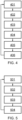
- Figure 4 is a schematic flow diagram illustrating a method of operation of the system 300 in a first mode, in which a bias is measured and determined for each of a plurality of predetermined drilling locations on a workpiece.
- the robotic drill is actuated to contact the surface of the workpiece contacting portion of the clamp to the workpiece to be machined.
- a first position of the drilling tool relative to the workpiece is measured using the metrology system.
- the servo motor is actuated to drive the clamp on to the workpiece to be machined, while measuring a force from the force sensor until a predetermined force has been reached.
- a second position of the drilling tool relative to the workpiece is measured using the metrology system.
- a bias is determined from a difference between the first and second measured positions.
- the determined bias is stored for the predetermined location. The method may then be repeated for further predetermined locations on the workpiece until all locations for drilling operations have been covered.
- the controller may perform the method as outlined in Figure 5 .
- a stored bias for a predetermined location of a workpiece to be machined is retrieved.
- the robotic drill is actuated to contact the surface of the workpiece contacting portion of the clamp at the predetermined location offset by the retrieved bias.
- the servo motor is actuated to drive the clamp on to the workpiece while measuring a force from the force sensor until a predetermined force has been reached.
- the drilling tool is operated to drill a hole at the predetermined location of the workpiece. The method may then be repeated until all locations for drilling have been covered.
- the position of the drilling tool may continue to be measured during the second mode of operation, which can be used to update a stored bias for the predetermined location.
- the second mode of operation may be carried out separately from the first mode, i.e. with the stored bias for each predetermined location having been previously determined.
- the optical metrology system may operate by locating the position of multiple LEDs on the drilling tool 201 and workpiece holder 302 so that when the robotic drill 301 performs a drilling operation the optical metrology system enables the drilling tool to drill a hole in the workpiece to a greater degree of accuracy than may be possible using positional encoders on the robotic drill alone.
- the optical metrology system may for example have a positional accuracy within around 0.1 mm of a nominal target position,
- the bias between an unclamped and clamped position can be used by the controller to predict what bias or offset to apply to the robotic drill for future drilling operations. Multiple bias measurements may be incorporated into a machine learning algorithm to predict a bias to be used for a robotic drilling system.
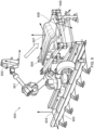
- Figure 6 is a drawing indicating various component parts of an example robotic drilling system 600, including a robotic drill 601 with a tool frame 602 comprising a drilling tool and clamp of the type described above.
- the robotic drill 601 is mounted on a robot base frame 603 that is associated with a robot system origin 604.
- a workpiece 605 to be machined is mounted on a workpiece holder 606, which may be attached to the robot base frame 603.
- the robot tool frame 602 is moved from the system origin 604 to a target 607, which may be determined by a 3D CAD model relative to an origin 608 of the workpiece 605 or workpiece holder 606. Operation of the robotic drill 601 may then be as described above.
- Figure 7 illustrates a more detailed example of a clamp attached to a drilling tool 700 of a robotic drill 701, the clamp having the general form as shown in Figure 2 and described above.
- the clamp comprises an electro-mechanical servo-driven mechanism 702 for high precision clamp-up, and has a non-skid surface 703 at the clamp "nose", or workpiece contacting portion.
- An integrated force feedback system 704 enables the servo to be driven until a desired force is met.
- Linear rails 705 with a pulley or timing belt ensure that force is applied to the structure, i.e. the workpiece to be machined, that is central to the clamp nose and not offset, which can amplify any skid.
- a rigid C-shaped frame 706 is designed to prevent distortion, deflection and skid of the clamp nose.
Landscapes
- Engineering & Computer Science (AREA)
- Mechanical Engineering (AREA)
- Robotics (AREA)
- Human Computer Interaction (AREA)
- Drilling And Boring (AREA)
- Manipulator (AREA)
Claims (15)
- Klemme (200), die zur Befestigung an einem Bohrwerkzeug (201) eines Roboterbohrers konfiguriert ist, wobei die Klemme (200) umfasst:einen Befestigungsabschnitt (220), der für die Befestigung an dem Bohrwerkzeug (201) konfiguriert ist;einen Rahmen (202), der relativ zu dem Befestigungsabschnitt (220) entlang einer Mittelachse (203) der Klemme (200) konzentrisch zu einer Bohrrichtung (221) des Bohrwerkzeugs (201) linear beweglich ist;einen Betätigungsmechanismus, der einen Servomotor (205) umfasst, der konfiguriert ist, um eine lineare Bewegung des Rahmens (202) relativ zu dem Bohrwerkzeug (201) anzutreiben;einen Werkstückkontaktabschnitt (206) an einem distalen Ende (207) des Rahmens (202), der eine Oberfläche (208) zum Kontaktieren einer Oberfläche eines zu bohrenden Werkstücks und eine Öffnung (209) umfasst, die einen Durchgang eines Bohrers (204) des Bohrwerkzeugs (201) zur Werkstückoberfläche ermöglicht; undeinen Kraftsensor (210), der angeordnet ist, um eine Kraft zu messen, die auf den Werkstückkontaktabschnitt (206) in der Bohrrichtung (221) wirkt,wobei der Rahmen (202) ein Paar Arme (211a, 211b), die sich in der Bohrrichtung (221) auf beiden Seiten der Mittelachse (203) erstrecken, und ein distales Endstück (212) aufweist, das sich zwischen dem Paar Arme (211a, 211b) erstreckt,dadurch gekennzeichnet, dassder Servomotor (205) konfiguriert ist, um jeden der Arme (211a, 211b) des Rahmens (202) durch Drehung jeweiliger Stangen (213a, 213b), die sich entlang jedes Arms (211a, 211b) erstrecken, anzutreiben.
- Klemme (200) nach Anspruch 1, wobei der Werkstückkontaktabschnitt (206) eine rutschfeste Oberfläche (208) zum Berühren der Werkstückoberfläche aufweist.
- Klemme (200) nach Anspruch 1, wobei die Arme (211a, 211b) und das Endstück (212) eine einheitliche Konstruktion darstellen.
- Klemme (200) nach Anspruch 1, umfassend eine Riemenscheibe oder einen Zahnriemen (214), der sich zwischen dem Paar Armen (211a, 211b) erstreckt und angeordnet ist, um die Drehung der Stangen (213a, 213b) zu synchronisieren.
- Roboterbohrsystem (300), umfassend:einen Roboterbohrer (301), der ein Bohrwerkzeug (201) aufweist;einen Werkstückhalter (302) zum Halten eines zu bearbeitenden Werkstücks;eine Klemme (200) nach einem vorstehenden Anspruch, die an dem Bohrwerkzeug (201) befestigt ist; undeine Steuereinheit (303), die zur Steuerung des Roboterbohrers (301) und der Klemme (200) angeschlossen und angeordnet ist,wobei die Steuereinheit (303) konfiguriert ist, um:den Roboterbohrer (301) zu betätigen, um die Oberfläche des Werkstückkontaktabschnitts (208) der Klemme (200) mit einem zu bearbeitenden Werkstück zu kontaktieren;den Servomotor (205) zu betätigen, um die Klemme (200) auf das Werkstück zu treiben, während eine Kraft von dem Kraftsensor (210) gemessen wird, bis eine vorbestimmte Kraft erreicht ist; unddas Bohrwerkzeug (201) zu betreiben, um ein Loch in das Werkstück zu bohren.
- Roboterbohrsystem (300) nach Anspruch 5, weiter umfassend ein Messsystem (215, 315, 304, 305) zum Messen einer Position des Bohrwerkzeugs (201) relativ zu dem zu bearbeitenden Werkstück, wobei das Messsystem eine erste Vielzahl von Bezugspunkten (215), die sich auf dem Roboterbohrer (301) befinden, und eine zweite Vielzahl von Bezugspunkten (315), die sich auf dem Werkstückhalter (302) befinden, umfasst.
- Roboterbohrsystem (300) nach Anspruch 6, wobei die Steuereinheit (303) konfiguriert ist, um Signale von der ersten und/oder zweiten Vielzahl von Bezugspunkten (215, 315) zu empfangen, um eine Position des Bohrwerkzeugs (201) relativ zu dem Werkstück zu bestimmen, wobei das Messsystem ein optisches Messsystem ist und die erste und zweite Vielzahl von Bezugspunkten (215, 315) optische Emitter umfassen, wobei das Messsystem eine Vielzahl von optischen Sensoren (304) umfasst, die angeordnet sind, um eine Position des Bohrwerkzeugs (201) relativ zu dem Werkstückhalter (302) auf der Grundlage von Signalen zu bestimmen, die von den optischen Sensoren (304) von der ersten und zweiten Vielzahl von optischen Emittern (215, 315) empfangen werden.
- Roboterbohrsystem (300) nach einem der Ansprüche 5 bis 7, wobei in einem ersten Modus die Steuereinheit (303) konfiguriert ist, um:den Roboterbohrer (301) zu betätigen, um die Oberfläche des Werkstückkontaktabschnitts (208) der Klemme (200) mit einer vorbestimmten Stelle auf dem zu bearbeitenden Werkstück zu kontaktieren;eine erste Position des Bohrwerkzeugs (201) relativ zum Werkstück mit dem Messsystem zu messen;den Servomotor (205) zu betätigen, um die Klemme (200) auf das Werkstück zu treiben, während eine Kraft von dem Kraftsensor (206) gemessen wird, bis eine vorbestimmte Kraft erreicht ist;eine zweite Position des Bohrwerkzeugs (201) relativ zum Werkstück mit dem Messsystem zu messen;eine Abweichung aus der Differenz zwischen der ersten und der zweiten gemessenen Position zu bestimmen; unddie bestimmte Abweichung für die vorbestimmte Stelle zu speichern,wobei die Steuereinheit (303) konfiguriert ist, um eine Abweichung für eine Vielzahl von vorbestimmten Stellen auf dem Werkstück zu bestimmen und zu speichern.
- Roboterbohrsystem nach einem der Ansprüche 5 bis 8, wobei in einem zweiten Modus die Steuereinheit (303) konfiguriert ist, um:eine gespeicherte Abweichung für eine vorbestimmte Stelle eines zu bearbeitenden Werkstücks abzurufen;den Roboterbohrer (201) zu betätigen, um die Oberfläche des Werkstückkontaktabschnitts (208) der Klemme (200) an der vorbestimmten Stelle zu kontaktieren, die um die abgerufene Abweichung versetzt ist;den Servomotor (205) zu betätigen, um die Klemme (200) auf das Werkstück zu treiben, während eine Kraft von dem Kraftsensor (206) gemessen wird, bis eine vorbestimmte Kraft erreicht ist; unddas Bohrwerkzeug (201) zu betreiben, um ein Loch an der vorbestimmten Stelle des Werkstücks zu bohren,wobei die Steuereinheit (303) konfiguriert ist, um eine Position des Bohrwerkzeugs (201) nach Betätigung des Servomotors (205) zu messen und die gespeicherte Abweichung für die vorbestimmte Stelle zu aktualisieren.
- Computerimplementiertes Verfahren zum Betreiben eines Roboterbohrers (301), wobei das Verfahren in einem ersten Modus umfasst:Ausgeben von Befehlen zum Betätigen des Roboterbohrers (301), um die Oberfläche des Werkstückkontaktabschnitts (208) einer Klemme (200) nach Anspruch 1, die an einem Bohrwerkzeug (201) des Roboterbohrers (301) befestigt ist, mit einer vorbestimmten Stelle auf dem zu bearbeitenden Werkstück zu kontaktieren;Empfangen von Messdaten, die für eine erste Position des Bohrwerkzeugs (201) relativ zum Werkstück repräsentativ sind, mit einem Messsystem;Ausgeben von Befehlen zum Betätigen eines Servomotors (205), um die Klemme (200) auf das Werkstück zu treiben, während eine Kraft von dem Kraftsensor (206) gemessen wird, bis eine vorbestimmte Kraft erreicht ist;Empfangen von Messdaten, die für eine zweite Position des Bohrwerkzeugs (201) relativ zum Werkstück repräsentativ sind, mit dem Messsystem;Bestimmen einer Abweichung aus einer Differenz zwischen der ersten und der zweiten gemessenen Position; undSpeichern der bestimmten Abweichung für die vorbestimmte Stelle,wobei der erste Modus für eine Vielzahl von vorbestimmten Stellen auf dem Werkstück wiederholt wird.
- Verfahren nach Anspruch 10, wobei das Verfahren weiter in einem zweiten Modus umfasst:Abrufen einer gespeicherten Abweichung für eine vorbestimmte Stelle auf einem zu bearbeitenden Werkstück;Ausgeben von Befehlen zum Betätigen des Roboterbohrers (301), um die Oberfläche des Werkstückkontaktabschnitts (208) der Klemme (200) an der vorbestimmten Stelle zu kontaktieren, die um die abgerufene Abweichung versetzt ist;Ausgeben von Befehlen zum Betätigen des Servomotors (205), um die Klemme (200) auf das Werkstück zu treiben, während eine Kraft von dem Kraftsensor (206) gemessen wird, bis eine vorbestimmte Kraft erreicht ist; undAusgeben von Befehlen zum Betreiben des Bohrwerkzeugs (201), um ein Loch an der vorbestimmten Stelle des Werkstücks zu bohren.
- Verfahren nach Anspruch 11, wobei der zweite Modus für eine Vielzahl von vorbestimmten Stellen auf dem zu bearbeitenden Werkstück wiederholt wird.
- Computerimplementiertes Verfahren zum Betreiben eines Roboterbohrers (301), wobei das Verfahren umfasst:Abrufen einer gespeicherten Abweichung für eine vorbestimmte Stelle eines zu bearbeitenden Werkstücks;Ausgeben von Befehlen zum Betätigen des Roboterbohrers (301), um eine Oberfläche des Werkstückkontaktabschnitts (208) einer Klemme (200) nach Anspruch 1, die an einem Bohrwerkzeug (201) des Roboterbohrers (301) befestigt ist, an der vorbestimmten Stelle, die um die abgerufene Abweichung versetzt ist, zu kontaktieren;Ausgeben von Befehlen zum Betätigen des Servomotors (205), um die Klemme (200) auf das Werkstück zu treiben, während eine Kraft von dem Kraftsensor (206) gemessen wird, bis eine vorbestimmte Kraft erreicht ist; undAusgeben von Befehlen zum Betreiben des Bohrwerkzeugs (201) zum Bohren eines Lochs an der vorbestimmten Stelle auf dem Werkstück.
- Verfahren nach Anspruch 13, wobei das Verfahren für eine Vielzahl von vorbestimmten Stellen auf dem Werkstück wiederholt wird.
- Computerprogramm, das Anweisungen umfasst, um eine computerisierte Steuereinheit zu veranlassen, das Verfahren nach einem der Ansprüche 10 bis 14 durchzuführen.
Applications Claiming Priority (2)
| Application Number | Priority Date | Filing Date | Title |
|---|---|---|---|
| GB2004306.3A GB2593501B (en) | 2020-03-25 | 2020-03-25 | Robot drilling clamp |
| PCT/GB2021/050723 WO2021191610A1 (en) | 2020-03-25 | 2021-03-25 | Robot drilling clamp and computer-implemented methods for operating a robotic drill |
Publications (3)
| Publication Number | Publication Date |
|---|---|
| EP4126476A1 EP4126476A1 (de) | 2023-02-08 |
| EP4126476C0 EP4126476C0 (de) | 2024-09-18 |
| EP4126476B1 true EP4126476B1 (de) | 2024-09-18 |
Family
ID=70546751
Family Applications (1)
| Application Number | Title | Priority Date | Filing Date |
|---|---|---|---|
| EP21716822.8A Active EP4126476B1 (de) | 2020-03-25 | 2021-03-25 | Roboterbohrklemme und computerimplementierte verfahren zum betrieb eines roboterbohrers |
Country Status (6)
| Country | Link |
|---|---|
| US (1) | US20230219240A1 (de) |
| EP (1) | EP4126476B1 (de) |
| CA (1) | CA3176753A1 (de) |
| ES (1) | ES2991392T3 (de) |
| GB (1) | GB2593501B (de) |
| WO (1) | WO2021191610A1 (de) |
Families Citing this family (3)
| Publication number | Priority date | Publication date | Assignee | Title |
|---|---|---|---|---|
| GB2616844A (en) * | 2022-03-20 | 2023-09-27 | True Position Robotics Ltd | Robot guidance using multiple frames |
| FR3140568B1 (fr) | 2022-10-07 | 2024-10-25 | Ledoux Finance | Système de travail de pièce comprenant une machine-outil, et procédé de travail correspondant |
| CN219486175U (zh) * | 2022-11-23 | 2023-08-08 | 智建机械技术有限公司 | 一种自动驾驶、精确定位钻孔机械人 |
Family Cites Families (10)
| Publication number | Priority date | Publication date | Assignee | Title |
|---|---|---|---|---|
| US4955119A (en) * | 1989-07-11 | 1990-09-11 | Imta | Multi-task end effector for robotic machining center |
| US4995148A (en) * | 1990-03-30 | 1991-02-26 | Imta | Robotically controlled multi-task end effector |
| EP1189022A1 (de) * | 2000-09-13 | 2002-03-20 | BAE SYSTEMS plc | Messverfahren, um die Position eines Zieles auf einem Objekt zu finden |
| JP2008536146A (ja) * | 2005-04-11 | 2008-09-04 | ファロ テクノロジーズ インコーポレーテッド | 3次元座標測定デバイス |
| ITTO20060581A1 (it) * | 2006-08-04 | 2008-02-05 | Bruno Bisiach | Dispositivo e metodo di lavorazione di un pezzo da lavorare, quale per esempio una struttura a guscio di un velivolo |
| US8926240B2 (en) * | 2010-07-23 | 2015-01-06 | Zagar Inc. | End effector |
| JP5801346B2 (ja) * | 2013-05-27 | 2015-10-28 | 富士重工業株式会社 | 穿孔装置及び穿孔方法 |
| US9964765B2 (en) * | 2015-09-11 | 2018-05-08 | The Boeing Company | Virtual display of the real-time position of a robotic device to a human operator positioned on an opposing side of an object |
| JP6924563B2 (ja) * | 2016-08-30 | 2021-08-25 | 川崎重工業株式会社 | 位置決め制御装置の制御方法及び位置決め制御装置 |
| DE102017213717A1 (de) * | 2017-08-07 | 2019-02-07 | Lufthansa Technik Ag | Bearbeitungsvorrichtung für ein Luftfahrzeug |
-
2020
- 2020-03-25 GB GB2004306.3A patent/GB2593501B/en active Active
-
2021
- 2021-03-25 US US17/913,582 patent/US20230219240A1/en active Pending
- 2021-03-25 WO PCT/GB2021/050723 patent/WO2021191610A1/en not_active Ceased
- 2021-03-25 CA CA3176753A patent/CA3176753A1/en active Pending
- 2021-03-25 EP EP21716822.8A patent/EP4126476B1/de active Active
- 2021-03-25 ES ES21716822T patent/ES2991392T3/es active Active
Also Published As
| Publication number | Publication date |
|---|---|
| CA3176753A1 (en) | 2021-09-30 |
| US20230219240A1 (en) | 2023-07-13 |
| GB2593501A (en) | 2021-09-29 |
| EP4126476C0 (de) | 2024-09-18 |
| WO2021191610A1 (en) | 2021-09-30 |
| GB2593501B (en) | 2024-06-05 |
| ES2991392T3 (es) | 2024-12-03 |
| GB202004306D0 (en) | 2020-05-06 |
| EP4126476A1 (de) | 2023-02-08 |
Similar Documents
| Publication | Publication Date | Title |
|---|---|---|
| EP4126476B1 (de) | Roboterbohrklemme und computerimplementierte verfahren zum betrieb eines roboterbohrers | |
| US7216408B2 (en) | Flexible rail multiaxis machine tool and method | |
| JP4928536B2 (ja) | 工作機械 | |
| US10209107B2 (en) | Geometric error identification method of multi-axis machine tool and multi-axis machine tool | |
| US8051754B2 (en) | Lathe, computer program for lathe control, and machining method by lathe | |
| US9656329B2 (en) | Machining jig for rotatably supporting workpiece with respect to tool of machine tool and machining system | |
| JP2014073571A (ja) | 面直倣い機構、これを備えた加工装置および加工方法 | |
| US9658610B2 (en) | Displacement and position measurement in machine tool | |
| JPS598501B2 (ja) | プログラム化可能な自動操作による自動応答性のワ−キング・センタ− | |
| US20250205895A1 (en) | Robot guidance using multiple frames | |
| EP2564989B1 (de) | Verfahren und Vorrichtung für Herstellungsoperationen | |
| CN112775718A (zh) | 机床的位置测量传感器的校正值测量方法和校正值测量系统 | |
| JP5235284B2 (ja) | 測定方法及び工作機械 | |
| US20120282052A1 (en) | Device for drilling a complex panel | |
| US6480757B1 (en) | Method of locating a workpiece on a computer numeric controlled machining system | |
| US20210379709A1 (en) | Machining center and workpiece processing method | |
| US11376667B2 (en) | Machining tool and workpiece measurement method | |
| JP5531640B2 (ja) | 工作機械の送り制御装置 | |
| JPWO2017051445A1 (ja) | 多関節ロボットのティーチングシステム | |
| JP2020059071A (ja) | 工作機械及び加工方法 | |
| JP2002283189A (ja) | 工作機械の熱変位測定方法 | |
| KR20200059357A (ko) | 로봇팔을 이용한 정밀 가공장치 및 이의 작동방법 | |
| KR20250073897A (ko) | 지지성질 가변 가능 엔드이펙터 장치 | |
| JPH01289606A (ja) | 非接触オンライン計測装置およびこの装置を用いて切削する方法 | |
| Calawa et al. | This paper was given at the 1994 SAE Aerofast Conference in Montreal, Quebec, Canada |
Legal Events
| Date | Code | Title | Description |
|---|---|---|---|
| STAA | Information on the status of an ep patent application or granted ep patent |
Free format text: STATUS: UNKNOWN |
|
| STAA | Information on the status of an ep patent application or granted ep patent |
Free format text: STATUS: THE INTERNATIONAL PUBLICATION HAS BEEN MADE |
|
| PUAI | Public reference made under article 153(3) epc to a published international application that has entered the european phase |
Free format text: ORIGINAL CODE: 0009012 |
|
| STAA | Information on the status of an ep patent application or granted ep patent |
Free format text: STATUS: REQUEST FOR EXAMINATION WAS MADE |
|
| 17P | Request for examination filed |
Effective date: 20221025 |
|
| AK | Designated contracting states |
Kind code of ref document: A1 Designated state(s): AL AT BE BG CH CY CZ DE DK EE ES FI FR GB GR HR HU IE IS IT LI LT LU LV MC MK MT NL NO PL PT RO RS SE SI SK SM TR |
|
| DAV | Request for validation of the european patent (deleted) | ||
| DAX | Request for extension of the european patent (deleted) | ||
| GRAP | Despatch of communication of intention to grant a patent |
Free format text: ORIGINAL CODE: EPIDOSNIGR1 |
|
| STAA | Information on the status of an ep patent application or granted ep patent |
Free format text: STATUS: GRANT OF PATENT IS INTENDED |
|
| INTG | Intention to grant announced |
Effective date: 20240321 |
|
| GRAS | Grant fee paid |
Free format text: ORIGINAL CODE: EPIDOSNIGR3 |
|
| GRAA | (expected) grant |
Free format text: ORIGINAL CODE: 0009210 |
|
| STAA | Information on the status of an ep patent application or granted ep patent |
Free format text: STATUS: THE PATENT HAS BEEN GRANTED |
|
| AK | Designated contracting states |
Kind code of ref document: B1 Designated state(s): AL AT BE BG CH CY CZ DE DK EE ES FI FR GB GR HR HU IE IS IT LI LT LU LV MC MK MT NL NO PL PT RO RS SE SI SK SM TR |
|
| REG | Reference to a national code |
Ref country code: GB Ref legal event code: FG4D |
|
| REG | Reference to a national code |
Ref country code: CH Ref legal event code: EP |
|
| REG | Reference to a national code |
Ref country code: IE Ref legal event code: FG4D |
|
| REG | Reference to a national code |
Ref country code: DE Ref legal event code: R096 Ref document number: 602021018971 Country of ref document: DE |
|
| U01 | Request for unitary effect filed |
Effective date: 20241003 |
|
| REG | Reference to a national code |
Ref country code: ES Ref legal event code: FG2A Ref document number: 2991392 Country of ref document: ES Kind code of ref document: T3 Effective date: 20241203 |
|
| U07 | Unitary effect registered |
Designated state(s): AT BE BG DE DK EE FI FR IT LT LU LV MT NL PT RO SE SI Effective date: 20241104 |
|
| PG25 | Lapsed in a contracting state [announced via postgrant information from national office to epo] |
Ref country code: GR Free format text: LAPSE BECAUSE OF FAILURE TO SUBMIT A TRANSLATION OF THE DESCRIPTION OR TO PAY THE FEE WITHIN THE PRESCRIBED TIME-LIMIT Effective date: 20241219 |
|
| PG25 | Lapsed in a contracting state [announced via postgrant information from national office to epo] |
Ref country code: HR Free format text: LAPSE BECAUSE OF FAILURE TO SUBMIT A TRANSLATION OF THE DESCRIPTION OR TO PAY THE FEE WITHIN THE PRESCRIBED TIME-LIMIT Effective date: 20240918 |
|
| PG25 | Lapsed in a contracting state [announced via postgrant information from national office to epo] |
Ref country code: RS Free format text: LAPSE BECAUSE OF FAILURE TO SUBMIT A TRANSLATION OF THE DESCRIPTION OR TO PAY THE FEE WITHIN THE PRESCRIBED TIME-LIMIT Effective date: 20241218 |
|
| PG25 | Lapsed in a contracting state [announced via postgrant information from national office to epo] |
Ref country code: RS Free format text: LAPSE BECAUSE OF FAILURE TO SUBMIT A TRANSLATION OF THE DESCRIPTION OR TO PAY THE FEE WITHIN THE PRESCRIBED TIME-LIMIT Effective date: 20241218 Ref country code: HR Free format text: LAPSE BECAUSE OF FAILURE TO SUBMIT A TRANSLATION OF THE DESCRIPTION OR TO PAY THE FEE WITHIN THE PRESCRIBED TIME-LIMIT Effective date: 20240918 Ref country code: GR Free format text: LAPSE BECAUSE OF FAILURE TO SUBMIT A TRANSLATION OF THE DESCRIPTION OR TO PAY THE FEE WITHIN THE PRESCRIBED TIME-LIMIT Effective date: 20241219 |
|
| U20 | Renewal fee for the european patent with unitary effect paid |
Year of fee payment: 5 Effective date: 20250225 |
|
| PG25 | Lapsed in a contracting state [announced via postgrant information from national office to epo] |
Ref country code: IS Free format text: LAPSE BECAUSE OF FAILURE TO SUBMIT A TRANSLATION OF THE DESCRIPTION OR TO PAY THE FEE WITHIN THE PRESCRIBED TIME-LIMIT Effective date: 20250118 |
|
| PG25 | Lapsed in a contracting state [announced via postgrant information from national office to epo] |
Ref country code: SM Free format text: LAPSE BECAUSE OF FAILURE TO SUBMIT A TRANSLATION OF THE DESCRIPTION OR TO PAY THE FEE WITHIN THE PRESCRIBED TIME-LIMIT Effective date: 20240918 |
|
| PGFP | Annual fee paid to national office [announced via postgrant information from national office to epo] |
Ref country code: NO Payment date: 20250319 Year of fee payment: 5 |
|
| PG25 | Lapsed in a contracting state [announced via postgrant information from national office to epo] |
Ref country code: CZ Free format text: LAPSE BECAUSE OF FAILURE TO SUBMIT A TRANSLATION OF THE DESCRIPTION OR TO PAY THE FEE WITHIN THE PRESCRIBED TIME-LIMIT Effective date: 20240918 Ref country code: PL Free format text: LAPSE BECAUSE OF FAILURE TO SUBMIT A TRANSLATION OF THE DESCRIPTION OR TO PAY THE FEE WITHIN THE PRESCRIBED TIME-LIMIT Effective date: 20240918 |
|
| PG25 | Lapsed in a contracting state [announced via postgrant information from national office to epo] |
Ref country code: SK Free format text: LAPSE BECAUSE OF FAILURE TO SUBMIT A TRANSLATION OF THE DESCRIPTION OR TO PAY THE FEE WITHIN THE PRESCRIBED TIME-LIMIT Effective date: 20240918 |
|
| PGFP | Annual fee paid to national office [announced via postgrant information from national office to epo] |
Ref country code: GB Payment date: 20250225 Year of fee payment: 5 |
|
| PGFP | Annual fee paid to national office [announced via postgrant information from national office to epo] |
Ref country code: ES Payment date: 20250417 Year of fee payment: 5 |
|
| PLBE | No opposition filed within time limit |
Free format text: ORIGINAL CODE: 0009261 |
|
| STAA | Information on the status of an ep patent application or granted ep patent |
Free format text: STATUS: NO OPPOSITION FILED WITHIN TIME LIMIT |
|
| 26N | No opposition filed |
Effective date: 20250619 |
|
| PG25 | Lapsed in a contracting state [announced via postgrant information from national office to epo] |
Ref country code: MC Free format text: LAPSE BECAUSE OF FAILURE TO SUBMIT A TRANSLATION OF THE DESCRIPTION OR TO PAY THE FEE WITHIN THE PRESCRIBED TIME-LIMIT Effective date: 20240918 |
|
| REG | Reference to a national code |
Ref country code: CH Ref legal event code: H13 Free format text: ST27 STATUS EVENT CODE: U-0-0-H10-H13 (AS PROVIDED BY THE NATIONAL OFFICE) Effective date: 20251023 |