EP4124792A1 - Behälter, insbesondere für einen flüssigwasserstofftank, der mit innenschienen zum einbau eines gerätemoduls versehen ist - Google Patents
Behälter, insbesondere für einen flüssigwasserstofftank, der mit innenschienen zum einbau eines gerätemoduls versehen ist Download PDFInfo
- Publication number
- EP4124792A1 EP4124792A1 EP22184514.2A EP22184514A EP4124792A1 EP 4124792 A1 EP4124792 A1 EP 4124792A1 EP 22184514 A EP22184514 A EP 22184514A EP 4124792 A1 EP4124792 A1 EP 4124792A1
- Authority
- EP
- European Patent Office
- Prior art keywords
- tank
- rails
- module
- central section
- rail
- Prior art date
- Legal status (The legal status is an assumption and is not a legal conclusion. Google has not performed a legal analysis and makes no representation as to the accuracy of the status listed.)
- Pending
Links
Images


Classifications
-
- F—MECHANICAL ENGINEERING; LIGHTING; HEATING; WEAPONS; BLASTING
- F17—STORING OR DISTRIBUTING GASES OR LIQUIDS
- F17C—VESSELS FOR CONTAINING OR STORING COMPRESSED, LIQUEFIED OR SOLIDIFIED GASES; FIXED-CAPACITY GAS-HOLDERS; FILLING VESSELS WITH, OR DISCHARGING FROM VESSELS, COMPRESSED, LIQUEFIED, OR SOLIDIFIED GASES
- F17C13/00—Details of vessels or of the filling or discharging of vessels
- F17C13/002—Details of vessels or of the filling or discharging of vessels for vessels under pressure
-
- F—MECHANICAL ENGINEERING; LIGHTING; HEATING; WEAPONS; BLASTING
- F17—STORING OR DISTRIBUTING GASES OR LIQUIDS
- F17C—VESSELS FOR CONTAINING OR STORING COMPRESSED, LIQUEFIED OR SOLIDIFIED GASES; FIXED-CAPACITY GAS-HOLDERS; FILLING VESSELS WITH, OR DISCHARGING FROM VESSELS, COMPRESSED, LIQUEFIED, OR SOLIDIFIED GASES
- F17C1/00—Pressure vessels, e.g. gas cylinder, gas tank, replaceable cartridge
-
- F—MECHANICAL ENGINEERING; LIGHTING; HEATING; WEAPONS; BLASTING
- F17—STORING OR DISTRIBUTING GASES OR LIQUIDS
- F17C—VESSELS FOR CONTAINING OR STORING COMPRESSED, LIQUEFIED OR SOLIDIFIED GASES; FIXED-CAPACITY GAS-HOLDERS; FILLING VESSELS WITH, OR DISCHARGING FROM VESSELS, COMPRESSED, LIQUEFIED, OR SOLIDIFIED GASES
- F17C13/00—Details of vessels or of the filling or discharging of vessels
- F17C13/08—Mounting arrangements for vessels
- F17C13/084—Mounting arrangements for vessels for small-sized storage vessels, e.g. compressed gas cylinders or bottles, disposable gas vessels, vessels adapted for automotive use
-
- F—MECHANICAL ENGINEERING; LIGHTING; HEATING; WEAPONS; BLASTING
- F17—STORING OR DISTRIBUTING GASES OR LIQUIDS
- F17C—VESSELS FOR CONTAINING OR STORING COMPRESSED, LIQUEFIED OR SOLIDIFIED GASES; FIXED-CAPACITY GAS-HOLDERS; FILLING VESSELS WITH, OR DISCHARGING FROM VESSELS, COMPRESSED, LIQUEFIED, OR SOLIDIFIED GASES
- F17C2201/00—Vessel construction, in particular geometry, arrangement or size
- F17C2201/01—Shape
- F17C2201/0104—Shape cylindrical
- F17C2201/0109—Shape cylindrical with exteriorly curved end-piece
-
- F—MECHANICAL ENGINEERING; LIGHTING; HEATING; WEAPONS; BLASTING
- F17—STORING OR DISTRIBUTING GASES OR LIQUIDS
- F17C—VESSELS FOR CONTAINING OR STORING COMPRESSED, LIQUEFIED OR SOLIDIFIED GASES; FIXED-CAPACITY GAS-HOLDERS; FILLING VESSELS WITH, OR DISCHARGING FROM VESSELS, COMPRESSED, LIQUEFIED, OR SOLIDIFIED GASES
- F17C2201/00—Vessel construction, in particular geometry, arrangement or size
- F17C2201/05—Size
- F17C2201/054—Size medium (>1 m3)
-
- F—MECHANICAL ENGINEERING; LIGHTING; HEATING; WEAPONS; BLASTING
- F17—STORING OR DISTRIBUTING GASES OR LIQUIDS
- F17C—VESSELS FOR CONTAINING OR STORING COMPRESSED, LIQUEFIED OR SOLIDIFIED GASES; FIXED-CAPACITY GAS-HOLDERS; FILLING VESSELS WITH, OR DISCHARGING FROM VESSELS, COMPRESSED, LIQUEFIED, OR SOLIDIFIED GASES
- F17C2201/00—Vessel construction, in particular geometry, arrangement or size
- F17C2201/05—Size
- F17C2201/056—Small (<1 m3)
-
- F—MECHANICAL ENGINEERING; LIGHTING; HEATING; WEAPONS; BLASTING
- F17—STORING OR DISTRIBUTING GASES OR LIQUIDS
- F17C—VESSELS FOR CONTAINING OR STORING COMPRESSED, LIQUEFIED OR SOLIDIFIED GASES; FIXED-CAPACITY GAS-HOLDERS; FILLING VESSELS WITH, OR DISCHARGING FROM VESSELS, COMPRESSED, LIQUEFIED, OR SOLIDIFIED GASES
- F17C2203/00—Vessel construction, in particular walls or details thereof
- F17C2203/01—Reinforcing or suspension means
- F17C2203/011—Reinforcing means
- F17C2203/013—Reinforcing means in the vessel, e.g. columns
-
- F—MECHANICAL ENGINEERING; LIGHTING; HEATING; WEAPONS; BLASTING
- F17—STORING OR DISTRIBUTING GASES OR LIQUIDS
- F17C—VESSELS FOR CONTAINING OR STORING COMPRESSED, LIQUEFIED OR SOLIDIFIED GASES; FIXED-CAPACITY GAS-HOLDERS; FILLING VESSELS WITH, OR DISCHARGING FROM VESSELS, COMPRESSED, LIQUEFIED, OR SOLIDIFIED GASES
- F17C2203/00—Vessel construction, in particular walls or details thereof
- F17C2203/03—Thermal insulations
-
- F—MECHANICAL ENGINEERING; LIGHTING; HEATING; WEAPONS; BLASTING
- F17—STORING OR DISTRIBUTING GASES OR LIQUIDS
- F17C—VESSELS FOR CONTAINING OR STORING COMPRESSED, LIQUEFIED OR SOLIDIFIED GASES; FIXED-CAPACITY GAS-HOLDERS; FILLING VESSELS WITH, OR DISCHARGING FROM VESSELS, COMPRESSED, LIQUEFIED, OR SOLIDIFIED GASES
- F17C2203/00—Vessel construction, in particular walls or details thereof
- F17C2203/06—Materials for walls or layers thereof; Properties or structures of walls or their materials
- F17C2203/0602—Wall structures; Special features thereof
- F17C2203/0612—Wall structures
- F17C2203/0626—Multiple walls
- F17C2203/0629—Two walls
-
- F—MECHANICAL ENGINEERING; LIGHTING; HEATING; WEAPONS; BLASTING
- F17—STORING OR DISTRIBUTING GASES OR LIQUIDS
- F17C—VESSELS FOR CONTAINING OR STORING COMPRESSED, LIQUEFIED OR SOLIDIFIED GASES; FIXED-CAPACITY GAS-HOLDERS; FILLING VESSELS WITH, OR DISCHARGING FROM VESSELS, COMPRESSED, LIQUEFIED, OR SOLIDIFIED GASES
- F17C2203/00—Vessel construction, in particular walls or details thereof
- F17C2203/06—Materials for walls or layers thereof; Properties or structures of walls or their materials
- F17C2203/0634—Materials for walls or layers thereof
- F17C2203/0636—Metals
- F17C2203/0646—Aluminium
-
- F—MECHANICAL ENGINEERING; LIGHTING; HEATING; WEAPONS; BLASTING
- F17—STORING OR DISTRIBUTING GASES OR LIQUIDS
- F17C—VESSELS FOR CONTAINING OR STORING COMPRESSED, LIQUEFIED OR SOLIDIFIED GASES; FIXED-CAPACITY GAS-HOLDERS; FILLING VESSELS WITH, OR DISCHARGING FROM VESSELS, COMPRESSED, LIQUEFIED, OR SOLIDIFIED GASES
- F17C2205/00—Vessel construction, in particular mounting arrangements, attachments or identifications means
- F17C2205/01—Mounting arrangements
- F17C2205/0153—Details of mounting arrangements
-
- F—MECHANICAL ENGINEERING; LIGHTING; HEATING; WEAPONS; BLASTING
- F17—STORING OR DISTRIBUTING GASES OR LIQUIDS
- F17C—VESSELS FOR CONTAINING OR STORING COMPRESSED, LIQUEFIED OR SOLIDIFIED GASES; FIXED-CAPACITY GAS-HOLDERS; FILLING VESSELS WITH, OR DISCHARGING FROM VESSELS, COMPRESSED, LIQUEFIED, OR SOLIDIFIED GASES
- F17C2209/00—Vessel construction, in particular methods of manufacturing
- F17C2209/21—Shaping processes
- F17C2209/2181—Metal working processes, e.g. deep drawing, stamping or cutting
-
- F—MECHANICAL ENGINEERING; LIGHTING; HEATING; WEAPONS; BLASTING
- F17—STORING OR DISTRIBUTING GASES OR LIQUIDS
- F17C—VESSELS FOR CONTAINING OR STORING COMPRESSED, LIQUEFIED OR SOLIDIFIED GASES; FIXED-CAPACITY GAS-HOLDERS; FILLING VESSELS WITH, OR DISCHARGING FROM VESSELS, COMPRESSED, LIQUEFIED, OR SOLIDIFIED GASES
- F17C2209/00—Vessel construction, in particular methods of manufacturing
- F17C2209/22—Assembling processes
- F17C2209/221—Welding
- F17C2209/222—Welding by friction
-
- F—MECHANICAL ENGINEERING; LIGHTING; HEATING; WEAPONS; BLASTING
- F17—STORING OR DISTRIBUTING GASES OR LIQUIDS
- F17C—VESSELS FOR CONTAINING OR STORING COMPRESSED, LIQUEFIED OR SOLIDIFIED GASES; FIXED-CAPACITY GAS-HOLDERS; FILLING VESSELS WITH, OR DISCHARGING FROM VESSELS, COMPRESSED, LIQUEFIED, OR SOLIDIFIED GASES
- F17C2209/00—Vessel construction, in particular methods of manufacturing
- F17C2209/23—Manufacturing of particular parts or at special locations
- F17C2209/232—Manufacturing of particular parts or at special locations of walls
-
- F—MECHANICAL ENGINEERING; LIGHTING; HEATING; WEAPONS; BLASTING
- F17—STORING OR DISTRIBUTING GASES OR LIQUIDS
- F17C—VESSELS FOR CONTAINING OR STORING COMPRESSED, LIQUEFIED OR SOLIDIFIED GASES; FIXED-CAPACITY GAS-HOLDERS; FILLING VESSELS WITH, OR DISCHARGING FROM VESSELS, COMPRESSED, LIQUEFIED, OR SOLIDIFIED GASES
- F17C2221/00—Handled fluid, in particular type of fluid
- F17C2221/01—Pure fluids
- F17C2221/012—Hydrogen
-
- F—MECHANICAL ENGINEERING; LIGHTING; HEATING; WEAPONS; BLASTING
- F17—STORING OR DISTRIBUTING GASES OR LIQUIDS
- F17C—VESSELS FOR CONTAINING OR STORING COMPRESSED, LIQUEFIED OR SOLIDIFIED GASES; FIXED-CAPACITY GAS-HOLDERS; FILLING VESSELS WITH, OR DISCHARGING FROM VESSELS, COMPRESSED, LIQUEFIED, OR SOLIDIFIED GASES
- F17C2223/00—Handled fluid before transfer, i.e. state of fluid when stored in the vessel or before transfer from the vessel
- F17C2223/01—Handled fluid before transfer, i.e. state of fluid when stored in the vessel or before transfer from the vessel characterised by the phase
- F17C2223/0146—Two-phase
- F17C2223/0153—Liquefied gas, e.g. LPG, GPL
- F17C2223/0161—Liquefied gas, e.g. LPG, GPL cryogenic, e.g. LNG, GNL, PLNG
-
- F—MECHANICAL ENGINEERING; LIGHTING; HEATING; WEAPONS; BLASTING
- F17—STORING OR DISTRIBUTING GASES OR LIQUIDS
- F17C—VESSELS FOR CONTAINING OR STORING COMPRESSED, LIQUEFIED OR SOLIDIFIED GASES; FIXED-CAPACITY GAS-HOLDERS; FILLING VESSELS WITH, OR DISCHARGING FROM VESSELS, COMPRESSED, LIQUEFIED, OR SOLIDIFIED GASES
- F17C2223/00—Handled fluid before transfer, i.e. state of fluid when stored in the vessel or before transfer from the vessel
- F17C2223/03—Handled fluid before transfer, i.e. state of fluid when stored in the vessel or before transfer from the vessel characterised by the pressure level
- F17C2223/033—Small pressure, e.g. for liquefied gas
-
- F—MECHANICAL ENGINEERING; LIGHTING; HEATING; WEAPONS; BLASTING
- F17—STORING OR DISTRIBUTING GASES OR LIQUIDS
- F17C—VESSELS FOR CONTAINING OR STORING COMPRESSED, LIQUEFIED OR SOLIDIFIED GASES; FIXED-CAPACITY GAS-HOLDERS; FILLING VESSELS WITH, OR DISCHARGING FROM VESSELS, COMPRESSED, LIQUEFIED, OR SOLIDIFIED GASES
- F17C2260/00—Purposes of gas storage and gas handling
- F17C2260/01—Improving mechanical properties or manufacturing
- F17C2260/011—Improving strength
-
- F—MECHANICAL ENGINEERING; LIGHTING; HEATING; WEAPONS; BLASTING
- F17—STORING OR DISTRIBUTING GASES OR LIQUIDS
- F17C—VESSELS FOR CONTAINING OR STORING COMPRESSED, LIQUEFIED OR SOLIDIFIED GASES; FIXED-CAPACITY GAS-HOLDERS; FILLING VESSELS WITH, OR DISCHARGING FROM VESSELS, COMPRESSED, LIQUEFIED, OR SOLIDIFIED GASES
- F17C2260/00—Purposes of gas storage and gas handling
- F17C2260/01—Improving mechanical properties or manufacturing
- F17C2260/016—Preventing slosh
-
- F—MECHANICAL ENGINEERING; LIGHTING; HEATING; WEAPONS; BLASTING
- F17—STORING OR DISTRIBUTING GASES OR LIQUIDS
- F17C—VESSELS FOR CONTAINING OR STORING COMPRESSED, LIQUEFIED OR SOLIDIFIED GASES; FIXED-CAPACITY GAS-HOLDERS; FILLING VESSELS WITH, OR DISCHARGING FROM VESSELS, COMPRESSED, LIQUEFIED, OR SOLIDIFIED GASES
- F17C2270/00—Applications
- F17C2270/01—Applications for fluid transport or storage
- F17C2270/0186—Applications for fluid transport or storage in the air or in space
- F17C2270/0189—Planes
-
- Y—GENERAL TAGGING OF NEW TECHNOLOGICAL DEVELOPMENTS; GENERAL TAGGING OF CROSS-SECTIONAL TECHNOLOGIES SPANNING OVER SEVERAL SECTIONS OF THE IPC; TECHNICAL SUBJECTS COVERED BY FORMER USPC CROSS-REFERENCE ART COLLECTIONS [XRACs] AND DIGESTS
- Y02—TECHNOLOGIES OR APPLICATIONS FOR MITIGATION OR ADAPTATION AGAINST CLIMATE CHANGE
- Y02E—REDUCTION OF GREENHOUSE GAS [GHG] EMISSIONS, RELATED TO ENERGY GENERATION, TRANSMISSION OR DISTRIBUTION
- Y02E60/00—Enabling technologies; Technologies with a potential or indirect contribution to GHG emissions mitigation
- Y02E60/30—Hydrogen technology
- Y02E60/32—Hydrogen storage
Definitions
- the present invention relates to a tank, in particular for a liquid hydrogen tank, as well as a liquid hydrogen tank provided with such a tank.
- liquid hydrogen is an ecological fuel that does not emit greenhouse gases, it is planned to develop its use and use it in the future in a wide variety of fields and in particular on aircraft, in particular on transport aircraft.
- liquid hydrogen In such a use in particular, the liquid hydrogen must be stored in a suitable tank.
- a liquid hydrogen tank comprises a complex assembly of structures and systems, such as pipes, sensors, anti-sloshing walls, which are mounted in an (internal) tank of the tank.
- the present invention relates to a tank, in particular for a liquid hydrogen tank, said tank comprising a central section provided with a wall, the object of which is to overcome these drawbacks.
- said tank comprises at least one rail, said rail being integrated into the wall of the central section of the tank so as to be accessible from inside the tank.
- said rail is welded to said wall.
- one or more rails are integrated into the wall of the tank.
- Such rails allow easy insertion and fixing inside the tank of a module comprising all the equipment, as specified below, which makes it possible in particular to remedy accessibility constraints and simplify manufacturing. and assembly of the tank.
- the rail is provided on an internal face with a slide intended to receive at least one connecting element, said slide allowing movement by translation of the connecting element or elements.
- the tank comprises a plurality of longitudinal rails integrated into the wall of the central section, being oriented so as to present directions parallel to each other.
- the tank comprises at least one frame provided with passage openings, adapted to be arranged transversely in the tank, being mounted on the rails.
- the tank comprises a plurality of connecting elements, each of said connecting elements being fixed to the frame by one of its ends and being provided at the other end with a head adapted to be able to slide by cooperating with the rail and being able to be fixed with the rail.
- the tank comprises a module formed of a plurality of frames linked together by means of equipment, said module being able to be arranged in the tank, by being mounted on the rails.
- the present invention also relates to a liquid hydrogen tank, which comprises a tank such as that described above.
- the present invention also relates to a method for manufacturing and assembling a tank such as that described above or a liquid hydrogen tank as mentioned above.
- the fixing step consists, in order to hold the module in position, in fixing the heads of the connecting elements to the rails.
- the tank 1 making it possible to illustrate the invention and represented schematically and partially in a particular embodiment on the figures 1 and 2 , is particularly suitable for mounting in a liquid hydrogen tank 10, such as that shown in the picture 3 .
- such a liquid hydrogen tank 10 generally comprises, in addition to tank 1 which is an internal tank, a second tank called an external tank (not shown).
- the inner tank is mounted in the outer tank, and it includes functional equipment specified below.
- a liquid hydrogen tank 10 is particularly well suited to equipping a mobile machine operating, at least partially, on hydrogen.
- the tank 10 is intended to equip an aircraft, in particular a transport aircraft.
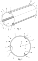
- the tank 1 comprises a central section 2 of cylindrical shape, representing a ferrule, of longitudinal axis XX.
- This central section 2 has a wall 3.
- the tank 1 can also comprise two domes 26A, 26B ( picture 3 ) each of which is mounted in the usual way at one of the ends 2A, 2B of the central section 2.
- the tank may comprise a central section having shapes other than a cylindrical shape, for example a conical shape or a shape with an oblong or arbitrary cross section.
- the shape of the tank can, in particular, be adapted to the space available for the arrangement of the liquid hydrogen tank, in particular when the latter is intended to equip a mobile machine, for example an aircraft.
- the tank 1 also comprises rails 4 which are integrated into the wall 3 of the central section 2 and are welded thereto, as specified below.
- the rails 4 are accessible from inside the tank 1.
- the central section 2 also comprises a plurality of elongated panels 5 (along the longitudinal axis XX), of curved (concave) shape in cross section.
- the curvature of each of the panels 5 corresponds to that of an arc of a circle with a radius equal to the radius R of the central section 2.
- the radius R defined between a central point O (located on the longitudinal axis XX) and the wall 3 has been represented.
- the panels 5 are identical, and between each pair of adjacent panels 5 is integrated a rail 4.
- the rails 4 are uniformly distributed transversely, namely equidistant from one rail to the neighboring rail.
- the central section 2 comprises three identical panels 5 and three rails 4 which are also identical.
- Each of the rails 4 comprises, as shown in the figure 4 , an elongated base 6.
- the base 6 preferably has a curved (concave) shape in cross section, with substantially the same curvature as that of the panels 5 of the central body 2.
- Each of the rails 4 is therefore welded to two adjacent panels 5.
- the rails 4 and the panels 5 are welded together via end-to-end longitudinal weld seams 7.
- this welding is carried out by means of friction stir welding of the FSW type (for “Friction Stir Welding”).
- FSW for “Friction Stir Welding”.
- other usual welding methods can also be used.
- Each of the rails 4 comprises a slide 8 on an internal face 9 of the base 6, as represented on the figure 4 .
- This slide 8, therefore accessible from inside the tank 1, is intended to allow movement by translation of connecting elements 16, as specified below.
- slider 8 comprises a housing 13 intended to receive a head 18 of a connecting element 16 and, as specified below, the housings 13 of the slides 8 of the rails 4 and the heads 18 of the connecting elements 16 have cooperating shapes.
- the slide 8 comprises two brackets 11 and 12 elongated.
- Each of these brackets 11 and 12 comprises a flat and elongated branch 11A, 12A, secured to the base 6, and a branch 11B, 12B (also flat and elongated) connected perpendicularly to the branch 11A, 12A respectively.
- the brackets 11 and 12 are arranged with their branches 11B and 12B facing each other so as to form a housing 13 provided with an opening 13A.
- brackets can be arranged in opposite directions, with their branches 11B and 12B moving away from each other.
- a connecting element of complementary shape is also provided.
- the brackets 11 and 12 can be inserts which are attached to the base 6. However, in a preferred embodiment, the brackets 11 and 12 and the base 6 form one and the same piece.
- each of these rails 4 is a profile, preferably extruded. It is thus possible to manufacture and use standard parts for the rails 4, which makes it possible in particular to reduce their manufacturing cost and therefore that of the tank 1.
- the longitudinal ends of the rails 4 are chamfered to facilitate the welding of the domes which are fixed to the ends of the tank 1 to close it.
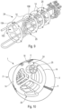
- the tank 1 comprises a plurality of frames 14, such as that shown in the figure 5 .
- Each of these frames 14 corresponds to a disk, with a diameter slightly smaller than that of the tank 1, as specified below.
- This disc is provided with passage openings 15A, 15B and 15C, of various shapes and sizes.
- the passage openings 15A and 15B can be intended (if necessary) for the passage of equipment.
- the 15C passage openings of larger sizes they allow the passage of the fluid (liquid hydrogen) so as to confer an anti-sloshing function on the frame 14.
- Each of the frames 14 is capable of being mounted transversely in the tank 1, preferably so that the disc forming the frame 14 is arranged orthogonally to the longitudinal axis X-X.
- Each of the frames 14 is mounted in the tank 1 by being linked to the rails 4.
- a plurality of connecting elements 16 are provided, such as that represented on the figures 6 and 7 , which are intended to allow the connection of the frames 14 to the rails 4.
- Each of the connecting elements 16 is fixed to a frame 14 by one 16A of its ends 16A, 16B.
- the end 16A is provided with two flat and identical branches 17A and 17B, which are arranged side by side in parallel so as to create a free space 18 into which an edge of the frame 14 is inserted.
- the end 16A of the connecting element 16 is fixed to the frame 14, preferably by welding.
- each of the connecting elements 16 is provided, at the other end 16B, with a head 18 capable of being able to slide in the rail 4 while being held there.
- the heads 18 of the connecting elements 16 and the housings 13 ( figure 4 ) of the slides 8 of the rails 4, intended to receive these heads 18, have cooperating shapes.
- cooperating shapes is meant identical shapes, but with a size of the contour of the head 18 slightly smaller than that of the housing 13 so as to allow movement by translation of the head 18 in the housing 13, while being held there.
- the head 18 and the housing 13 have a rectangular shape in cross section. Cooperating shapes other than a rectangular shape can of course be provided for the heads 18 and the housings 13.
- the ends 16A and 16B of the connecting element 16 are linked together via a tab 20 ( figure 6 ) to form two lateral grooves 21 and 22.
- branches 11A and 11B of brackets 11 and 12 penetrate, respectively, in the side grooves 21 and 22, which ensures good stability.
- the tank 1 comprises a module 24 formed of a plurality of frames 14 linked together by means of equipment 25, in particular pipes, sensors, a cooling finger, ..., as specified below.
- This module 24 is able to be inserted into the tank 1, as shown in the picture 3 and specified below, via the connecting elements 16 and the rails 4.
- a process for manufacturing and assembling the tank 1, as described above, of the tank 10 for liquid hydrogen is specified below.
- the manufacturing step E1 consists in manufacturing a tank 1 comprising a central section 2 provided with integrated rails 4 ( figure 1 ). To do this, panels 5 and rails 4 are used, preferably of standard shape, which are arranged alternately, and each rail 4 is welded on either side to a panel 5 so as to obtain the 2 central section with integrated 4 rails.
- the mounting step E2 consists, for its part, in mounting equipment 25 in a plurality of frames 14 arranged side by side and provided with connecting elements 16, so as to form a module 24, as shown in the figure 9 .
- the equipment that is identified by a general reference relates to all of the equipment that must be arranged inside the tank 1 and which is necessary for its operation, as the internal tank of a liquid hydrogen tank 10 .
- These are mainly pipes (or pipes).
- part of the equipment 25, in particular pipes is passed through some of the passage openings 15A and 15B of the frames 14, and more precisely in particular individual pipes through the passage openings 15A of reduced diameter and pipe bundles through the passage openings 15B of larger diameter.
- the equipment 25 comprises pipes, sensors, a cooling finger, etc., and in particular all the usual elements necessary to generate the low temperatures required for the storage of liquid hydrogen.
- This assembly step E2 is carried out outside the tank 1, which makes it possible to remedy the accessibility constraints existing in the tank 1.
- Each of the frames 14 of the module 24 is also provided with connecting elements 16 of the same number as the number of rails of the tank 1. These connecting elements 16 are fixed by their end 16A to the frame 14 and they are positioned on the periphery of the frame 14 so as to be able to be introduced into the slides 8 of the rails 4 when the module 24 is mounted in the tank 1.
- the following insertion step E3 consists of inserting the module 24 (as a unitary assembly) into the central section 2 of the tank 1, from one of the ends 2A, 2B ( figure 1 ) of the central section 2. This insertion is carried out by a translation of the module 24 via a sliding of the heads 18 of the connecting elements 16 in the slides 8 of the rails 4.
- the fixing step E4 is implemented, for its part, after the insertion step E3 when the module 24 is completely inserted (or installed) and is in its final position in the tank 1, as represented on the figure 10 .
- the fixing step E4 consists in holding the module 24 in position by any type of known means and for example by fixing the heads 18 of the connecting elements 16 to the rails 4.
- the heads 18 of the connecting elements 16 are welded to the rails 4.
- Various usual welding methods can be used to carry out this welding, and in particular friction stir welding of the FSW type (for “Friction Stir Welding” in English) or a linear friction welding of the LFW type (for “Linear Friction Welding” in English).
- a locking or locking system is provided for locking the heads 18 of the connecting elements 16 in the rails 4.
- the locking system may comprise, for each connecting element , a pin which is provided on the head of the connecting element, which is elastically constrained, and which is configured to penetrate into an orifice made in the rail, when the frame (on which the connecting element is fixed) arrives in its final position, during the insertion of the module in the central section.
- one of the panels 5 of the tank 1 is removed, to allow a view of the interior of the tank 1 and in particular the module 24 provided with the frames 14 and the equipment 25, which is installed there.
- the assembly process for obtaining a vessel 1 for a liquid hydrogen tank 10, for example as shown in the picture 3 comprises other steps, for example a step of fixing domes on the central section, which do not fall within the scope of the present invention and are not described further.
Landscapes
- Engineering & Computer Science (AREA)
- Mechanical Engineering (AREA)
- General Engineering & Computer Science (AREA)
- Filling Or Discharging Of Gas Storage Vessels (AREA)
Applications Claiming Priority (1)
| Application Number | Priority Date | Filing Date | Title |
|---|---|---|---|
| FR2108276A FR3125857A1 (fr) | 2021-07-29 | 2021-07-29 | Cuve, en particulier pour réservoir à hydrogène liquide, pourvu de rails internes pour la mise en place d’un module d’équipements. |
Publications (1)
| Publication Number | Publication Date |
|---|---|
| EP4124792A1 true EP4124792A1 (de) | 2023-02-01 |
Family
ID=77999137
Family Applications (1)
| Application Number | Title | Priority Date | Filing Date |
|---|---|---|---|
| EP22184514.2A Pending EP4124792A1 (de) | 2021-07-29 | 2022-07-12 | Behälter, insbesondere für einen flüssigwasserstofftank, der mit innenschienen zum einbau eines gerätemoduls versehen ist |
Country Status (4)
| Country | Link |
|---|---|
| US (1) | US12486947B2 (de) |
| EP (1) | EP4124792A1 (de) |
| CN (1) | CN115681794A (de) |
| FR (1) | FR3125857A1 (de) |
Families Citing this family (1)
| Publication number | Priority date | Publication date | Assignee | Title |
|---|---|---|---|---|
| US20250333185A1 (en) * | 2024-04-30 | 2025-10-30 | Airbus Operations Sas | Method for mounting a hydrogen box in a for a hydrogen-powered aircraft |
Citations (5)
| Publication number | Priority date | Publication date | Assignee | Title |
|---|---|---|---|---|
| US2860809A (en) * | 1957-02-14 | 1958-11-18 | Skyline Products Inc | Tank baffle |
| WO2005085099A1 (en) * | 2004-03-10 | 2005-09-15 | Aker Finnyards Oy | A method of planning and manufacturing an lng storage tank or the like and an aluminium lng storage tank manufactured using the method |
| WO2012065616A1 (de) * | 2010-11-16 | 2012-05-24 | Nordic Yards Wismar Gmbh | Tank für transport und/oder lagerung von kryogenen flüssigkeiten |
| US20180066796A1 (en) * | 2016-09-02 | 2018-03-08 | AccuAir Control Systems, LLC | Systems, devices and methods for modular pressure vessels |
| EP3421864A1 (de) * | 2017-06-26 | 2019-01-02 | Ateliers et Chantiers de la Grande Bruyere (ACGB) | Flüssig-erdgastank für kraftfahrzeuge |
Family Cites Families (6)
| Publication number | Priority date | Publication date | Assignee | Title |
|---|---|---|---|---|
| US3235344A (en) * | 1963-02-18 | 1966-02-15 | Chevron Res | Hydrocarbon conversion catalytic reactor |
| AU9181582A (en) * | 1982-01-05 | 1983-07-14 | J.R. Wyllie & Sons Pty Ltd | Metal tanks |
| JP4078522B2 (ja) * | 2002-01-31 | 2008-04-23 | Jfeスチール株式会社 | ハイブリッド型水素貯蔵容器および容器への水素貯蔵方法 |
| CN110701478B (zh) * | 2019-11-18 | 2025-02-07 | 大连大学 | 便于拆装且有效换热的金属氢化物储氢容器 |
| CN111256032A (zh) * | 2020-01-17 | 2020-06-09 | 缪岩杉 | 剧毒介质死瓶无泄漏处理器 |
| GB2596808B (en) * | 2020-07-06 | 2023-12-06 | Bae Systems Plc | A method of manufacturing a pressure vessel |
-
2021
- 2021-07-29 FR FR2108276A patent/FR3125857A1/fr not_active Ceased
-
2022
- 2022-07-12 EP EP22184514.2A patent/EP4124792A1/de active Pending
- 2022-07-25 US US17/872,311 patent/US12486947B2/en active Active
- 2022-07-29 CN CN202210909036.6A patent/CN115681794A/zh active Pending
Patent Citations (5)
| Publication number | Priority date | Publication date | Assignee | Title |
|---|---|---|---|---|
| US2860809A (en) * | 1957-02-14 | 1958-11-18 | Skyline Products Inc | Tank baffle |
| WO2005085099A1 (en) * | 2004-03-10 | 2005-09-15 | Aker Finnyards Oy | A method of planning and manufacturing an lng storage tank or the like and an aluminium lng storage tank manufactured using the method |
| WO2012065616A1 (de) * | 2010-11-16 | 2012-05-24 | Nordic Yards Wismar Gmbh | Tank für transport und/oder lagerung von kryogenen flüssigkeiten |
| US20180066796A1 (en) * | 2016-09-02 | 2018-03-08 | AccuAir Control Systems, LLC | Systems, devices and methods for modular pressure vessels |
| EP3421864A1 (de) * | 2017-06-26 | 2019-01-02 | Ateliers et Chantiers de la Grande Bruyere (ACGB) | Flüssig-erdgastank für kraftfahrzeuge |
Also Published As
| Publication number | Publication date |
|---|---|
| US20230036429A1 (en) | 2023-02-02 |
| CN115681794A (zh) | 2023-02-03 |
| FR3125857A1 (fr) | 2023-02-03 |
| US12486947B2 (en) | 2025-12-02 |
Similar Documents
| Publication | Publication Date | Title |
|---|---|---|
| EP2304368B1 (de) | Wärmetauscher und gehäuse für den wärmetauscher | |
| FR2680288A1 (fr) | Procede de fabrication d'une douille de connecteur et cette douille. | |
| EP2491328A1 (de) | Wärmetauscherkopf | |
| WO2010003807A1 (fr) | Echangeur de chaleur et carter pour l'echangeur | |
| FR2929458A1 (fr) | Dispositif de fixation d'un chemin de cables en fils sur une tige filetee | |
| EP2142834A2 (de) | Vorrichtung für eine vorgespannte versiegelungsverbindung mit flanschen | |
| EP4124792A1 (de) | Behälter, insbesondere für einen flüssigwasserstofftank, der mit innenschienen zum einbau eines gerätemoduls versehen ist | |
| FR3066240A1 (fr) | Support et ensemble support | |
| WO2010052194A1 (fr) | Plaque collectrice pour echangeur de chaleur et echangeur de chaleur comportant une telle plaque | |
| FR2459546A1 (fr) | Couvercle de bloc a fusibles | |
| EP2732517B1 (de) | Klammer zum verbinden von gitterrinnen für kabel | |
| EP2260553A2 (de) | Vorrichtung zur befestigung mehrerer zusammengefasster kabel | |
| EP4124791B1 (de) | Behälter, insbesondere für einen flüssigwasserstofftank, der mit mindestens einer kuppel versehen ist, die durch eine äussere schweissnaht befestigt ist | |
| FR3091493A1 (fr) | Maillon de chaîne | |
| EP0745532B1 (de) | Profilstäbe zum Zusammenbau eines Stuhlgerüstes, etwa eines Flugzeugsitzes und Verfahren für den Zusammenbau unter Benutzung dieser Profilstäbe | |
| EP3001132A1 (de) | Herstellungsverfahren eines wärmetauschers | |
| FR3100587A1 (fr) | Dispositif de fixation et systeme comportant ce dispositif de fixation | |
| EP0197812B1 (de) | Wärmetauscher mit schraubenförmigen Rohren mit Haltevorrichtungen | |
| EP2471152B1 (de) | Kammflansch für hochspannungskabel | |
| FR2933179A1 (fr) | Echangeur de chaleur | |
| WO2006035149A1 (fr) | Intercalaire d'échange de chaleur pour un dispositif d'échange de chaleur | |
| FR3004758A1 (fr) | Dispositif de maintien d'elements de forme allongee d'une turbomachine d'aeronef | |
| EP4207506A1 (de) | Bausatz für einen elektrischen verbinder und elektrischer verbinder | |
| EP3987591A1 (de) | Verbindungsmittel zwischen zwei teilen einer sammelschiene | |
| FR2818028A1 (fr) | Contact femelle a cage avec un module porte-lames a ressort d'accompagnement |
Legal Events
| Date | Code | Title | Description |
|---|---|---|---|
| PUAI | Public reference made under article 153(3) epc to a published international application that has entered the european phase |
Free format text: ORIGINAL CODE: 0009012 |
|
| STAA | Information on the status of an ep patent application or granted ep patent |
Free format text: STATUS: THE APPLICATION HAS BEEN PUBLISHED |
|
| AK | Designated contracting states |
Kind code of ref document: A1 Designated state(s): AL AT BE BG CH CY CZ DE DK EE ES FI FR GB GR HR HU IE IS IT LI LT LU LV MC MK MT NL NO PL PT RO RS SE SI SK SM TR |
|
| STAA | Information on the status of an ep patent application or granted ep patent |
Free format text: STATUS: REQUEST FOR EXAMINATION WAS MADE |
|
| 17P | Request for examination filed |
Effective date: 20230707 |
|
| RBV | Designated contracting states (corrected) |
Designated state(s): AL AT BE BG CH CY CZ DE DK EE ES FI FR GB GR HR HU IE IS IT LI LT LU LV MC MK MT NL NO PL PT RO RS SE SI SK SM TR |
|
| STAA | Information on the status of an ep patent application or granted ep patent |
Free format text: STATUS: EXAMINATION IS IN PROGRESS |
|
| 17Q | First examination report despatched |
Effective date: 20250210 |