EP0745532B1 - Profilstäbe zum Zusammenbau eines Stuhlgerüstes, etwa eines Flugzeugsitzes und Verfahren für den Zusammenbau unter Benutzung dieser Profilstäbe - Google Patents
Profilstäbe zum Zusammenbau eines Stuhlgerüstes, etwa eines Flugzeugsitzes und Verfahren für den Zusammenbau unter Benutzung dieser Profilstäbe Download PDFInfo
- Publication number
- EP0745532B1 EP0745532B1 EP96401167A EP96401167A EP0745532B1 EP 0745532 B1 EP0745532 B1 EP 0745532B1 EP 96401167 A EP96401167 A EP 96401167A EP 96401167 A EP96401167 A EP 96401167A EP 0745532 B1 EP0745532 B1 EP 0745532B1
- Authority
- EP
- European Patent Office
- Prior art keywords
- profile
- structure according
- flanges
- structural element
- assembly
- Prior art date
- Legal status (The legal status is an assumption and is not a legal conclusion. Google has not performed a legal analysis and makes no representation as to the accuracy of the status listed.)
- Expired - Lifetime
Links
- 238000000034 method Methods 0.000 title description 4
- 210000001364 upper extremity Anatomy 0.000 claims description 4
- 238000005304 joining Methods 0.000 claims description 2
- ZJFJVRPLNAMIKH-UHFFFAOYSA-N pseudo-u Chemical compound O=C1NC(=O)C(C)=CN1C1OC(COP(O)(=S)OC2C(OC(C2)N2C(N=C(N)C=C2)=O)COP(O)(=S)OC2C(OC(C2)N2C(N=C(N)C=C2)=O)COP(O)(=S)OC2C(OC(C2)N2C(N=C(N)C=C2)=O)COP(O)(=S)OC2C(OC(C2)N2C(NC(=O)C(C)=C2)=O)COP(O)(=S)OC2C(OC(C2)N2C3=C(C(NC(N)=N3)=O)N=C2)COP(O)(=S)OC2C(OC(C2)N2C3=NC=NC(N)=C3N=C2)COP(O)(=S)OC2C(OC(C2)N2C3=NC=NC(N)=C3N=C2)COP(O)(=S)OC2C(OC(C2)N2C(N=C(N)C=C2)=O)COP(O)(=S)OC2C(OC(C2)N2C(NC(=O)C(C)=C2)=O)COP(O)(=S)OC2C(OC(C2)N2C(NC(=O)C(C)=C2)=O)COP(O)(=S)OC2C(OC(C2)N2C3=C(C(NC(N)=N3)=O)N=C2)COP(O)(=S)OC2C(OC(C2)N2C3=C(C(NC(N)=N3)=O)N=C2)COP(O)(=S)OC2C(OC(C2)N2C3=C(C(NC(N)=N3)=O)N=C2)COP(O)(=S)OC2C(OC(C2)N2C3=NC=NC(N)=C3N=C2)CO)C(O)C1 ZJFJVRPLNAMIKH-UHFFFAOYSA-N 0.000 claims 1
- 230000000903 blocking effect Effects 0.000 description 2
- 230000000295 complement effect Effects 0.000 description 2
- 238000004519 manufacturing process Methods 0.000 description 2
- 239000000956 alloy Substances 0.000 description 1
- 229910045601 alloy Inorganic materials 0.000 description 1
- 229910052782 aluminium Inorganic materials 0.000 description 1
- XAGFODPZIPBFFR-UHFFFAOYSA-N aluminium Chemical compound [Al] XAGFODPZIPBFFR-UHFFFAOYSA-N 0.000 description 1
- 238000004873 anchoring Methods 0.000 description 1
- 230000000712 assembly Effects 0.000 description 1
- 238000000429 assembly Methods 0.000 description 1
- 230000003100 immobilizing effect Effects 0.000 description 1
- 238000007373 indentation Methods 0.000 description 1
- 238000012423 maintenance Methods 0.000 description 1
- 229910052751 metal Inorganic materials 0.000 description 1
- 239000002184 metal Substances 0.000 description 1
- 238000003860 storage Methods 0.000 description 1
Images


Classifications
-
- B—PERFORMING OPERATIONS; TRANSPORTING
- B64—AIRCRAFT; AVIATION; COSMONAUTICS
- B64D—EQUIPMENT FOR FITTING IN OR TO AIRCRAFT; FLIGHT SUITS; PARACHUTES; ARRANGEMENT OR MOUNTING OF POWER PLANTS OR PROPULSION TRANSMISSIONS IN AIRCRAFT
- B64D11/00—Passenger or crew accommodation; Flight-deck installations not otherwise provided for
- B64D11/06—Arrangements of seats, or adaptations or details specially adapted for aircraft seats
- B64D11/0696—Means for fastening seats to floors, e.g. to floor rails
-
- B—PERFORMING OPERATIONS; TRANSPORTING
- B64—AIRCRAFT; AVIATION; COSMONAUTICS
- B64D—EQUIPMENT FOR FITTING IN OR TO AIRCRAFT; FLIGHT SUITS; PARACHUTES; ARRANGEMENT OR MOUNTING OF POWER PLANTS OR PROPULSION TRANSMISSIONS IN AIRCRAFT
- B64D11/00—Passenger or crew accommodation; Flight-deck installations not otherwise provided for
- B64D11/06—Arrangements of seats, or adaptations or details specially adapted for aircraft seats
- B64D11/0649—Seats characterised by special features for reducing weight
-
- F—MECHANICAL ENGINEERING; LIGHTING; HEATING; WEAPONS; BLASTING
- F16—ENGINEERING ELEMENTS AND UNITS; GENERAL MEASURES FOR PRODUCING AND MAINTAINING EFFECTIVE FUNCTIONING OF MACHINES OR INSTALLATIONS; THERMAL INSULATION IN GENERAL
- F16B—DEVICES FOR FASTENING OR SECURING CONSTRUCTIONAL ELEMENTS OR MACHINE PARTS TOGETHER, e.g. NAILS, BOLTS, CIRCLIPS, CLAMPS, CLIPS OR WEDGES; JOINTS OR JOINTING
- F16B2200/00—Constructional details of connections not covered for in other groups of this subclass
- F16B2200/30—Dovetail-like connections
-
- Y—GENERAL TAGGING OF NEW TECHNOLOGICAL DEVELOPMENTS; GENERAL TAGGING OF CROSS-SECTIONAL TECHNOLOGIES SPANNING OVER SEVERAL SECTIONS OF THE IPC; TECHNICAL SUBJECTS COVERED BY FORMER USPC CROSS-REFERENCE ART COLLECTIONS [XRACs] AND DIGESTS
- Y02—TECHNOLOGIES OR APPLICATIONS FOR MITIGATION OR ADAPTATION AGAINST CLIMATE CHANGE
- Y02T—CLIMATE CHANGE MITIGATION TECHNOLOGIES RELATED TO TRANSPORTATION
- Y02T50/00—Aeronautics or air transport
- Y02T50/40—Weight reduction
-
- Y—GENERAL TAGGING OF NEW TECHNOLOGICAL DEVELOPMENTS; GENERAL TAGGING OF CROSS-SECTIONAL TECHNOLOGIES SPANNING OVER SEVERAL SECTIONS OF THE IPC; TECHNICAL SUBJECTS COVERED BY FORMER USPC CROSS-REFERENCE ART COLLECTIONS [XRACs] AND DIGESTS
- Y10—TECHNICAL SUBJECTS COVERED BY FORMER USPC
- Y10T—TECHNICAL SUBJECTS COVERED BY FORMER US CLASSIFICATION
- Y10T403/00—Joints and connections
- Y10T403/70—Interfitted members
- Y10T403/7062—Clamped members
Definitions
- the invention relates to a specially shaped intended for the assembly of the structural elements of a seat such as an aircraft seat, and a structure of seat including such profile.
- the aircraft seat structures currently known include one or more front foot elements, one or more rear foot elements and one element seat, rigidly assembled to the foot elements thanks to two profiles arranged transversely to the seat, placed horizontally when the seat is in its normal position of use.
- These profiles have a shape of cylindrical tube as illustrated by documents EP-A-53 012, EP-A-286 471, EP-A-495 318, EP-A-496,658, US-A-3,145,051, US-A-4,718,719, US-A-5,152 578 and GB-A-2 232 584.
- EP-A-0 042 565 describes in particular a profile according to the preamble of claim 1.
- the invention therefore aims to overcome the disadvantages of current seat structures, and more particularly to reduce the cost price, decrease weight, facilitate and optimize the process Manufacturing. These objectives naturally assume, by elsewhere, that the performance required in particular at the crushing is assured.
- the invention therefore also objective of proposing an aircraft seat structure which is particularly well suited to mass production.
- the seat structure object of the invention allows independent anchoring of the seat element of the structure with respect to the front foot and the foot rear, transverse.
- the invention provides a profile specially intended for rigid assembly, by axial sliding and clamping mechanical, structural elements of a seat, more especially of aircraft presenting, the features of claim 1.
- the invention also provides a seat structure, according to claim 13.
- the arrangement of the assembled structural elements can be set continuously and independently for each structural element. Although fast and able to provide sufficient resistance to crushing, the profiles used also have a self-alignment capacity taking into account possible deformations of the aircraft floor to which the seat.
- the invention applies more particularly to seats aircraft.
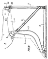
- the structure 1 of such a seat includes in particular a or more front leg elements 2, one or more rear leg elements 3, and a seat element 4.
- the seat element 4 is rigidly assembled to the front 2 and rear 3 foot elements by means of two assembly profiles 5 forming beams, which, in the achievement considered, are identical to each other.
- the two profiles of assembly used would be, without being strictly identical to each other, at least similar.
- Profiles 5 can not only fill their assembly function but also beam stiffening.
- Structure 1 also includes one or more struts 6, connecting crosspieces 7 and template profiles baggage 8. Furthermore, the seat element 4 is extended, backwards and upwards, by an element of file 9.
- Elements 2, 3, 4 and the profile assembly 5 are made of metal, in particular of alloy aluminum.
- the shape of these elements 2, 3, 4 and profile 5 is determined according to different characteristics that they must have, in particular of size, weight, shape, rigidity, etc.
- This profile is specially intended for assembly rigid by axial sliding and mechanical tightening of structural elements 2, 3, 4.
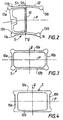
- Profile 5 presents in cross section (corresponding to the plan of figure 1), a general form of H. In this embodiment, the section 5 is therefore open.
- the central core 10 makes it possible to define a plane median transverse P, and a median longitudinal plane Q.
- the planes P and Q are perpendicular to each other the other.
- the different wings 12 are generally analogous to each other.
- the two pairs of wings 11a, 11b are separated one from the other.
- the two wings 12 of each pair of wings 11a, 11b are two by two opposite on either side of soul 10.
- the profile 5 therefore comprises two pairs of wings 13a, 13b.
- the assembly profile 5 presents two planes of symmetry, respectively P and Q.
- the four wings 12 are similar to each other and in particular identical.
- Each wing 12 extends in a straight line and perpendicularly, or substantially perpendicularly, relative to the core 10, at the end thereof.
- a wing Towards her free edge opposite the core 10, a wing includes a projection 14. This projection 14 is directed at least towards the plane P. In the embodiment shown in Figure 1, the projection 14 is also directed opposite the plane P.
- the wings 12, with their projection 14, have for function of participating in axial sliding guidance and blocking of structural elements 2, 3, 4 as well as this is described below.
- a projection 14 is inscribed in a circular contour envelope.
- the projection 14 has a sector-shaped outer face circular extending over an angle of the order of 300 °.
- the opening of the circular sector can be different and be between 280 ° and 340 °, and especially between 295 ° and 315 °.
- the wings 12 have a thickness greater than that of soul 10. For example, on the order of 50% larger.
- the maximum size of a projection 14 is the order of twice the thickness of wing 12, or three times the thickness of the core 10.
- a rounding is provided to the junction between each wing 12 and the core 10.
- FIG 2 illustrates an alternative embodiment of the section 5 of Figure 1. This profiled is in the form of pseudo-H.
- At least one of the wings 12 has a shape in at least two straight sections slightly inclined with respect to each other.
- the wings of the pair of wings 11a extend in a straight line, while that each of the wings of the pair of wings 11b has a form in two sections 50, 51 rectilinear slightly tilted relative to each other by a few degrees, the junction between the two sections being in the vicinity of the core 10, that is to say of the plane Q.
- the section 50 adjoining the core 10, of short length is perpendicular to the core 10.
- the section 51, of greater length than the section 50 is parallel to the wings of the pair 11a.
- This last pair of wings is directed towards the outside of profile 5, the angle with respect to the normal to the core 10 being of a few degrees, especially less than 10 °.
- each wing of the pair 11b has a length slightly greater than that of the wing of the pair 11a.
- FIG. 3 illustrates an alternative embodiment of the section 5 in which this last one has, in cross section a shape general closed tubular, namely rectangular.
- the profile 5 then has two cores 10a, 10b generally similar between them, parallel to each other, separated from each other the other, straight.
- the profile 5 has, moreover, a pair of wings 12a, 12b generally analogous to each other, separated from each other, parallel to each other, straight, joining the ends of the two cores 10a, 10b where there are projections 14.
- FIG. 4 illustrates an alternative embodiment of the profile of Figure 3.
- the cores 10a, 10b are of enlarged thicknesses.
- the wings 12a, 12b are thinner towards the plane Q and more very thick towards the cores 10a, 10b.
- the projections 14 extend mainly in the direction perpendicular to the Q plane.
- Tubular profiles as described have for advantage of having moments of inertia and resistance torsional in principle better than for a profile open as previously described.
- a structural element 2, 3, 4 has at least an assembly means 15 with at least one profile assembly 5 arranged transversely (Figure 5).
- the assembly means 15 has a complementary shape that of profile 5.
- the front foot element 2 includes such a means assembly 15 towards its upper free end part. he the same is true for the rear foot element 3.
- the seat element 4 has two assembly means 15 for respectively, the element of front foot 2 and rear foot element 3.
- One of these two assembly means 15 is located towards the end free front of the seat element 4 while the other is located towards its posterior free end from which extends the backrest element 9.
- An assembly means 15 includes two housings such as 16a, 16b or recesses such as 17a, 17b.
- clamping means such as 21, 22 respectively.
- the two housings 16a, 16b or recesses 17a, 17b are generally similar to each other. They stretch transversely to the structural element 2, 3, 4. This means that the structural element 2, 3, 4 extending in a general direction from the plane of the figure 2, the housing or recess 16a, 16b, 17a, 17b extends perpendicular to the plane of said figure.
- the two housings 16a, 16b or recesses 17a, 17b assembly means 15 are arranged substantially parallel to each other and facing each other, and this, from a free face 20 of the element of structure 2, 3, 4 into which they lead.
- These two housings 16a, 16b or recesses 17a, 17b have the function of receiving, by axial sliding, two wings 12 opposite a pair of wings 13a, 13b of a assembly profile 5.
- the wings 12 are tight mechanically against the faces of the housings 16a, 16b or recesses 17a, 17b by means of clamping means 21, 22.
- a housing 16a, 16b is characterized by the fact that it is limited by two opposite faces and, in the occurrence, parallel to each other being separated from each other by an empty space opening onto the face 20 and forming, in contrast, a bottom 23.
- a depression 17a, 17b is characterized by the presence of only one face, and not of two, this face being located opposite a notched part 24. This face reaches on one side the free face 20 of the element and, from the other side forms a bottom 25.
- the bottom 23, 25 of the housing 16a, 16b or of the depression 17a, 17b includes a bulge 26.
- the projection 14 and bulge 26 are intended to cooperate with each other. To this end, they have forms complementary.
- a bulge 26 is part of a envelope of circular contour, and in particular, to a form of circular sector, the angle of which is between 100 ° and 340 °.
- the bulge 26 of each of these two housing is directed to the housing opposite, as well than opposite of it.
- the bulge 26 of each of them is directed opposite the other facing depression.
- a housing 16a, 16b or depression 17a, 17b extends in a straight line and substantially perpendicular to the free face 20 where it opens.
- two housings 16a, 16b or recesses 17a, 17b, provided with the bulges 26, are similar between them, especially identical.
- the clamping means 21, 22 comprise a part 27, 28 having at least one bearing face on at least one wing 12 of the assembly profile 5, as well as a screw tightening 29, 30, axis 29a, 30a.
- Clamping screw 29, 30 is capable of ensuring the clamping of the part 27, 28 against the corresponding wing 12 of the profile 5, and against the housing 16a, 16b or the recess 17a, 17b of the element of structure 2, 3, 4.
- the seating element 4 which has two means assembly 15 identical to each other.
- Each of these two assembly means 15 is of the type comprising two housings 16a, 16b. These are formed in two projecting parts 31 of the element of structure 4 separated from each other by a part notched intermediate 32.
- the part 27 is an integral part of the structural element 4. More specifically, the part 27 forms part of the housing 16a and part of the part projection 31 in which it is formed. Housing 16a is then extended towards the inside of the element structure 4 and beyond its bulge 26 by a groove 33 sufficiently elongated to give elasticity necessary for clamping the part 27, by means of the screw 29 whose axis 29a is substantially perpendicular to the housing 16a, 16b.
- Each structural element 2, 3 comprises then an assembly means 15 of the type having two recesses 17a, 17b formed on the two opposite faces, limiting on both sides an indented part intermediate 24.
- This has, in cross section transverse a general form of pseudo U having a soul 34 and two wings corresponding to the two recesses 17a, 17b.
- the part 28 is then distinct from the element of structure 2, 3. It has two bearing surfaces 35a, 35b, opposite each other. Exhibit 28 is for cooperate with the U-shaped indented part 24.
- the clamping screw 30 then has its axis 30a substantially parallel to the depressions 17a, 17b and substantially perpendicular to the core 34.
- Each of the screws 29, 30 has a thread 36 and a clamping head 37 forming a shoulder 38.
- the part 27 has an orifice 39 allowing the passage of the screw 29.
- the part 27 also has a shoulder for the shoulder 38 of the screw 29.
- the part 27a of the element of structure 4 forming part of the projecting part 31, located on the other side of the housing 16a, is provided with a internal thread cooperating with thread 36.
- clamping means 21 only for housing 16a and wing 12 corresponding.
- No clamping means required for housing 16b can be considered.
- the screw 29 is located in the immediate vicinity of the bulge 26, in order to have the maximum tightening torque.
- the part 28 is in the form of a profiled element square or rectangular section provided with a tapped hole 40 with which the thread 36 of the clamping screw cooperates 30, which passes through an orifice 41 provided in the element of structure, a shoulder 42 being provided to cooperate with the corresponding shoulder 38 of the head 37.
- the part 28 includes two broken angles 43 likely to follow the shape of the bulges 26.
- the assembly means 15 are all of the push-in type given the shape of the profile 5 implemented.
- clamping means a part having a function similar to that of the part 28 already described. However, this piece is then placed outside profile 5, the inside being inaccessible.
- FIG. 7 which, compared with the embodiment of FIG. 6, differs in that the two housings 16a, 16b, at instead of being separated from each other by a deep part indented such that 32 are connected to each other by a part 52 in which the tapped clamping hole extends of screw 29, which tapped hole passes at the rear of the housing or even through the housing opposite to that where finds the head 37 of the screw 29.
- the groove 33 is placed opposite the head 37.
- assembly means 15 comprising housings 16a, 16b or recesses 17a, 17b and clamping means 21, 22 can be rigidly joined to each other, at by means of an assembly profile 5. And this in the different realizations considered.
- a first pair of wings 13a of the assembly profile 5 is assembled in the two housings 16a, 16b or recesses 17a, 17b of one of the structural elements 4, while the other couple of wings 13b is assembled in the two recesses 17a, 17b or housings 16a, 16b of a second structural element 2, 3.
- the two faces free 20 of the two structural elements assembled in which are housed the housings 16a, 16b or recesses 17a, 17b, are located in the immediate vicinity from each other while being spaced from each other.
- a structural element 4 according to the first variant of realization, is assembled by means of a profile assembly 5 to a structural element 2, 3 according to the second variant.
- the invention would be applicable in the event that structural elements are assembled of the same variant - first or second.
- the two axes 29a, 30a of the clamping screws 29, 30 of the assembly are substantially perpendicular to each other.
- the method of assembling a structure 1 consists in making the wings 12, 12a, 12b of the assembly profiles 5 with the housings 16a, 16b or recesses 17a, 17b, and this, by axial sliding, the clamping screws 29, 30 then being unscrewed.
Landscapes
- Engineering & Computer Science (AREA)
- Aviation & Aerospace Engineering (AREA)
- Mutual Connection Of Rods And Tubes (AREA)
Claims (37)
- Profil, durch axiales Einschieben und mechanisches Einklemmen insbesondere zur starren Verbindung der Elemente (2, 3, 4) eines Sitzgestells, insbesondere von Luftfahrzeugen, bestimmt, mit einem Querschnittsprofil in der Grundform eines H mit wenigstens einem zentralen Steg (10), und mit zwei Paaren (11a, 11b) von Schenkeln (12), die Schenkeln (12) jedes Schenkelpaares (11a, 11b) gegenüberliegend sind in bezug auf der längsverlaufenden Mittelebenen (Q) des zentralen Stegs (10), die Schenkel (12) sich, zu dem ende des zentralen Stegs (10), in einer generell senkrechten Richtung erstrecken, dadurch gekennzeichnet, dass jede Schenkel (12), zu ihrem Ende, die gegenüberliegen des stegs (10) ist, zumindest einen Ansatz (14) aufweist, der eine Aussenfläche in Form eines Kreisausschmitts hat, die Aussenfläche zumindest teilweise zur querverlaufenden Mittlebene (P) des zentralen Stegs (10) gerichtet ist, die Funktion des Ansatz ist es, der Führung beim axialen Einschieben und der starren Verbindung der Elemente des Gestells mitzuwirken.
- Profil nach Anspruch 1, dadurch gekennzeichnet, dass sich wenigstens einer der Schenkel (12) geradlinig erstreckt.
- Profil nach einem der Ansprüche 1 oder 2, dadurch gekennzeichnet, dass wenigstens einer der Schenkel (12) eine Form mit wenigstens zwei geradlinigen Abschnitten aufweist, die leicht zueinander geneigt sind.
- Profil nach Anspruch 3, dadurch gekennzeichnet, dass die beiden Abschnitte um einige Grad zueinander geneigt sind.
- Profil nach einem der Ansprüche 3 oder 4, dadurch gekennzeichnet, dass sich die Verbindungsstelle von zwei Abschnitten in der Nähe der Ebene Q und insbesondere des zentralen Stegs (10) befindet.
- Profil nach einem der Ansprüche 1 bis 5, dadurch gekennzeichnet, dass ein Ansatz (14) auch entgegengesetzt zur querverlaufenden Mittelebene (P) gerichtet ist.
- Profil nach einem der Ansprüche 1 bis 6, dadurch gekennzeichnet, dass der Kreisausschnitt einen Winkel zwischen 280° und 340°, insbesondere zwischen 295° und 315° aufweist.
- Profil nach einem der Ansprüche 1 bis 7, dadurch gekennzeichnet, dass der Schenkel (12) eines Schenkelpaares (11a, 11b) geringfügig länger ist als der gegenüberliegende.
- Profil nach einem der Ansprüche 1 bis 8, dadurch gekennzeichnet, dass es ein Querschnittsprofil in Form eines H hat, wobei die Schenkel (12) eines ersten Schenkelpaares (11a, 11b) geradlinig und in bezug auf einen sich in der Mitte befindenden leicht geneigt sind, während die Schenkel eines zweiten Schenkelpaares (11a, 11b) in zwei Abschnitten leicht zueinander geneigt sind; dabei sind die Schenkel des zweiten Paares geringfügig länger als die des ersten Paares.
- Profil nach einem der Ansprüche 1 bis 7, dadurch gekennzeichnet, dass die querverlaufenden Mittelebenen (P) und die längsverlaufenden Mittelbenen (Q) des Stegs (10) zwei Symmetrieebenen des gesamten Profils (5) bilden, wobei die Schenkel (12) identisch sind.
- Profil, durch axiales Einschieben und mechanisches Einklemmen insbesondere zur starren Verbindung der Elemente (2, 3, 4) eines Sitgestells, insbesondere von Luftfahrzeugen, bestimmt, mit einem Querschnittsprofil in der Grundform einer geschlossen rechteckig Röhrenform mit zwei in grossen und ganzen untereinander gleichen und voneinander beabstandeten stegen (10a, 10b), und mit einem Paar von im grossen und ganzen untereinander gleichen, voneinander beabstandeten Schenkeln (12a, 12b), die die Enden der beiden Stege (10a, 10b) miteinander verbinden, die Schenkel (12a, 12b) sich, zu der Ende der Stegen (10a, 10b), in einer generell senkrechten Richtung zu der Stegen (10a, 10b) erstrecken, dadurch gekennzeichnet, dass jede Schenkel (12a, 12b), zu ihrem Ende, einen Ansatz (14) aufweist, der eine Aussenfläche in Form eines kreisausschnitts hat, die Aussenfläche zumindest teilweise zur querlaufenden Mittelebene (P) der zentralen Stegen (10a, 10b) gerichtet ist die Funktion des Ansatz ist es, der Führung beim axialen Einschieben und der Starren Verbindung der Elemente des Gestells mitzuwirken.
- Profil nach Anspruch 11, dadurch gekennzeichnet, dass die querverlaufenden Mittelebenen (P) und die längsverlaufenden Mittelebenen (Q) der Stegen (10a, 10b) zwei Symmetrieebenen des gesamten Profils (5) bilden, wobei die Schenkel (12) identisch sind.
- Struktur eines Sitzes mit Sitzflächenauflageelementen und Rücklehneelementen, die Struktur einen Gestellelement (2, 3, 4) hat und einen Profil nach einem der Ansprüche 1 bis 12 hat, dadurch gekennzeichnet, dass der Gestellelement zwei im grossen und ganzen untereinander gleiche Aufnahmen (16a, 16b) bzw. Vertiefungen (17a, 17b) aufweist, die sich in Querrichtung, die sich definiert, als der Schnittpunkt der mit Sitzflächenauflageelementen und Rücklehneelementen bildenten Ebenen, erstrecken und von einer freien Fläche (20) des Gestellelements (2, 3, 4) ausgehend, in die sie einmünden, annähernd parallel und einander gegenüberliegend angeordnet sind, wobei diese beiden Aufnahmen (16a, 16b) bzw. Vertiefungen (17a, 17b) die Schenkel (12, 12a, 12b) eines Verbindungprofils (5) durch axiales Einschieben aufnehmen, die Schenkel (12, 12a, 12b) mit Hilfe von Klemm-Mitteln (21, 22) mechanisch zwischen den Flächen der Aufnahmen (16a, 16b) bzw. Vertiefungen (17a, 17b) eingeklemmnt werden.
- Struktur nach Anspruch 13, dadurch gekennzeichnet, dass das Ende (23, 25) Aufnahme (16a, 16b) bzw. Vertiefung (17a, 17b), das der freien Fläche (20), in die sie einmündet, gegenüberliegt, eine Verstärkung (26) aufweist, die dazu bestimmt ist, mit einem Ansatz (14) zusammenzuwirken, der zum freien Rand des Schenkels (12, 12a, 12b) Verbindungsprofils (5) hin gelegen ist.
- Struktur nach Anspruch 14, dadurch gekennzeichnet, dass die Verstärkung (26) einer Aufnahme (16a, 16b) bzw. Vertiefung (17a, 17b), hin zur gegenüberliegender und/oder auf der entgegengesetzten Seite liegenden Aufnahme (16a, 16b) bzw. Vertiefung (17a, 17b) gerichtet ist.
- Struktur nach einem der Ansprüche 13 bis 15, dadurch gekennzeichnet, dass die Aufnahme (16a, 16b) bzw. Vertiefung (17a, 17b) sich geradlinig oder annähernd geradlinig und senkrecht oder annähernd senkrecht zur freien Fläche (20) erstreckt, in die sie einmündet, um so der Form des Profils (5) zu entsprechen.
- Struktur nach einem der Ansprüche 14 bis 16, dadurch gekennzeichnet, dass eine Verstärkung (26) in eine Hüllkurve mit einer kreisförmigen Kontur einbeschrieben ist.
- Struktur nach Anspruch 17, dadurch gekennzeichnet, dass die Verstärkung (26) eine Fläche in Form eines Kreisausschnitts aufweist.
- Struktur nach Anspruch 18, dadurch gekennzeichnet, dass der Kreisausschnitt einen Winkel zwischen 100° und 340°aufweist.
- Struktur nach einem der Ansprüche 13 bis 19, dadurch gekennzeichnet, dass die beiden Aufnahmen (16a, 16b) bzw. Vertiefungen (17a, 17b) untereinander gleich sind, insbesondere identisch sind.
- Struktur nach Anspruch 13, dadurch gekennzeichnet, dass die beiden Aufnahmen (16a, 16b) in zwei vorstehenden Abschnitten (31) des Gestellelements (4) ausgebildet sind, die von einem eingebuchteten Zwischenabschnitt (32) getrennt bzw. durch einen Abschnitt (52), in den sich das Gewinde eines Klemm-Mittels (21) erstreckt, miteinander verbunden sind.
- Struktur nach Anspruch 13, dadurch gekennzeichnet, dass die beiden Vertiefungen (17a, 17b) in den beiden Flächen ausgebildet sind, die einen eingebuchteten Zwischenabschnitt (24) beidseits begrenzen.
- Gestellement nach Anspruch 22, dadurch gekennzeichnet, dass der eingebuchtete Abschnitt (24) eine Grundform annähernd wie ein U hat, dessen beide Schenkel die Verstärkungen (26) bilden.
- Struktur nach Anspruch 13, dadurch gekennzeichnet, dass die Klemm-Mittel (21, 22) ein Teil (27, 28) umfassen, das wenigstens eine Auflagefläche an wenigstens einem Schenkel (12, 12a, 12b) des Verbindungsprofils (5) aufweist, wie auch eine Schraube (29, 30) zum Festklemmen des Teils (27, 28) am entsprechen Schenkel (12) des Verbindungsprofils (5) und in der Aufnahme (16a, 16b) bzw. Vertiefung (17a, 17b) des Gestellelements.
- Struktur nach Anspruch 24, dadurch gekennzeichnet, dass das Teil (27) wesentlicher Bestandteil des Gestellelements (4) ist.
- Struktur nach Anspruch 25, dadurch gekennzeichnet, dass das Teil (27) einen Teil der Aufnahme (16a, 16b) des Gestellelements (4) bildet.
- Struktur nach Anspruch 26, dadurch gekennzeichnet, dass eine Aufnahme (16a, 16b) durch eine Vertiefung (33) ins Innere des Gestellelements (4) verlängert ist, die dem Teil (27) die notwendige Elastizität für das Einklemmen gibt.
- Struktur nach Anspruch 27, dadurch gekennzeichnet, dass das Teil (28) vom Gestellelements (2, 3) getrennt ist.
- Struktur nach Anspruch 28, dadurch gekennzeichnet, dass das Teil (28) zwei, insbesondere zwei sich gegenüberliegende Auflageflächen (35a, 35b) aufweist.
- Struktur nach einem der Ansprüche 13 bis 29, dadurch gekennzeichnet, dass es zwei Aufnahmen (16a, 16b) und ein zu den Klemm-Mitteln (21) gehörendes Teil (27) aufweist, die ein wesentlicher Bestandteil des Gestellelements (4) und in einem vorspringenden Abschnitt vorgesehen sind.
- Struktur nach Anspruch 30, dadurch gekennzeichnet, dass die Achse (29a) der Klemmschraube (29) annähernd senkrecht zu den Aufnahmen (16a, 16b) verläuft.
- Struktur nach einem der Ansprüche 13 bis 29, dadurch gekennzeichnet, dass es zwei in einem eingebuchteten Abschnitt (24) vorgesehene Vertiefungen (17a, 17b) aufweist, in dem ein eingesetztes Teil (28), das zu den Klemm-Mitteln (22) gehört, mit dem Gestellelement (2, 3) zusammenwirken kann.
- Struktur nach Anspruch 32, dadurch gekennzeichnet, dass die Achse (30a) der Klemmschraube (30) annähernd parallel zu den Vertiefungen (17a, 17b) verläuft.
- Struktur nach einem der Ansprüche 13 bis 33, dadurch gekennzeichnet, dass das Gestellelement ein vorderes Fusselement (2) oder ein hinteres Fusselement (3) für einen Sitz bildet.
- Struktur nach einem der Ansprüche 13 bis 33, dadurch gekennzeichnet, dass das Gestellelement ein Sitzflächenauflageelement (4) ist.
- Struktur nach Anspruch 13, dadurch gekennzeichnet, dass es mit einem oder mehreren Gestellelementen, die vorderen Fuss bilden, einem oder mehreren Gestellelementen, die hinteren Fusse (3) bilden und einem Gestellelement, der Sitzflächenauflage (4) bildet, die mit Hilfe von zwei Verbindungsprofilen (5) untereinander verbunden sind.
- Sitzgestell nach Anspruch 36,dadurch gekennzeichnet, dass die beiden Verbindungsprofile (5) identisch sind und parallel zueinander verlaufen.
Applications Claiming Priority (2)
| Application Number | Priority Date | Filing Date | Title |
|---|---|---|---|
| FR9506483 | 1995-05-31 | ||
| FR9506483A FR2734786B1 (fr) | 1995-05-31 | 1995-05-31 | Profile et procede d'assemblage d'elements de structure de siege d'aeronef, elements de structure, assemblage et structure ainsi realises |
Publications (2)
| Publication Number | Publication Date |
|---|---|
| EP0745532A1 EP0745532A1 (de) | 1996-12-04 |
| EP0745532B1 true EP0745532B1 (de) | 2002-03-27 |
Family
ID=9479556
Family Applications (1)
| Application Number | Title | Priority Date | Filing Date |
|---|---|---|---|
| EP96401167A Expired - Lifetime EP0745532B1 (de) | 1995-05-31 | 1996-05-31 | Profilstäbe zum Zusammenbau eines Stuhlgerüstes, etwa eines Flugzeugsitzes und Verfahren für den Zusammenbau unter Benutzung dieser Profilstäbe |
Country Status (5)
| Country | Link |
|---|---|
| US (1) | US5762440A (de) |
| EP (1) | EP0745532B1 (de) |
| JP (1) | JP3090311B2 (de) |
| DE (2) | DE69620048T2 (de) |
| FR (1) | FR2734786B1 (de) |
Families Citing this family (5)
| Publication number | Priority date | Publication date | Assignee | Title |
|---|---|---|---|---|
| DE19961425B4 (de) * | 1999-12-17 | 2005-10-20 | Zf Lemfoerder Metallwaren Ag | Kraftfahrzeugbauteil |
| US10973329B2 (en) * | 2018-06-04 | 2021-04-13 | Telescope Casual Furniture, Inc. | Furniture and method for assembling furniture |
| US11266246B2 (en) | 2018-06-04 | 2022-03-08 | Telescope Casual Furniture, Inc. | Furniture and method for assembling furniture |
| USD927216S1 (en) | 2019-05-22 | 2021-08-10 | Telescope Casual Furniture, Inc. | Seat |
| USD961283S1 (en) | 2019-06-04 | 2022-08-23 | Telescope Casual Furniture, Inc. | Seat |
Family Cites Families (16)
| Publication number | Priority date | Publication date | Assignee | Title |
|---|---|---|---|---|
| US1167155A (en) * | 1914-05-01 | 1916-01-04 | Derby & Company Inc P | Corner-joint. |
| FR1148478A (fr) * | 1955-12-23 | 1957-12-10 | Francais Isolants | Perfectionnements apportés aux joints hétérogènes |
| US3309096A (en) * | 1964-02-26 | 1967-03-14 | Inka Egons | Split circular sealing element |
| US3785600A (en) * | 1972-01-25 | 1974-01-15 | 1P Ind Chimica Arredamento S P | Adjustable mounting assemblies for groups of seats in aircraft or other vehicles |
| DE3022640A1 (de) * | 1980-06-18 | 1982-01-07 | Ignaz Vogel Gmbh Und Co Kg - Fahrzeugsitze, 7500 Karlsruhe | Fahrgastsitz |
| US4783040A (en) * | 1985-06-10 | 1988-11-08 | Aickin Development Corporation | Non-metallic strut system |
| FR2641584B1 (fr) * | 1988-01-18 | 1991-05-10 | Caoutchouc Manuf Plastique | Perfectionnement a un dispositif de jonctionnement de panneaux ou de realisation de conduits |
| US5251857A (en) * | 1988-06-27 | 1993-10-12 | Grice Gordon J | Suspendable conduit bracket system |
| US5090835A (en) * | 1989-12-11 | 1992-02-25 | Cox Eugene J | Picture frame connecting system |
| CH681383A5 (de) * | 1990-04-11 | 1993-03-15 | Alusuisse Lonza Services Ag | |
| ES2024916A6 (es) * | 1990-08-03 | 1992-03-01 | Figueras Ind Sa | Mejoras en el objeto de la patente principal n{ 8903161 por "estructura para la formacion de filas de asientos y asiento formado con la misma". |
| DE9017470U1 (de) * | 1990-12-24 | 1991-03-14 | Ignaz Vogel Gmbh Und Co Kg - Fahrzeugsitze, 7500 Karlsruhe, De | |
| US5277512A (en) * | 1992-03-16 | 1994-01-11 | Pdl Holdings Ltd. | Joint for detachable connection of structural members |
| US5549710A (en) * | 1993-02-03 | 1996-08-27 | Etablissements Proteor | System for assembling two components of a prosthesis in a plurality of adjustable positions |
| GB2277438A (en) * | 1993-04-21 | 1994-11-02 | Flight Equip & Eng | Aircraft seats |
| DE4317307A1 (de) * | 1993-05-25 | 1994-12-01 | Hans Joachim Muehl | Verfahren zum Verbinden von zwei Werkteilen |
-
1995
- 1995-05-31 FR FR9506483A patent/FR2734786B1/fr not_active Expired - Fee Related
-
1996
- 1996-05-30 US US08/655,462 patent/US5762440A/en not_active Expired - Fee Related
- 1996-05-31 DE DE69620048T patent/DE69620048T2/de not_active Expired - Fee Related
- 1996-05-31 DE DE0745532T patent/DE745532T1/de active Pending
- 1996-05-31 EP EP96401167A patent/EP0745532B1/de not_active Expired - Lifetime
- 1996-05-31 JP JP08139166A patent/JP3090311B2/ja not_active Expired - Fee Related
Also Published As
| Publication number | Publication date |
|---|---|
| DE745532T1 (de) | 1997-05-15 |
| EP0745532A1 (de) | 1996-12-04 |
| FR2734786A1 (fr) | 1996-12-06 |
| US5762440A (en) | 1998-06-09 |
| DE69620048D1 (de) | 2002-05-02 |
| JP3090311B2 (ja) | 2000-09-18 |
| JPH092396A (ja) | 1997-01-07 |
| FR2734786B1 (fr) | 1997-07-11 |
| DE69620048T2 (de) | 2002-10-31 |
Similar Documents
| Publication | Publication Date | Title |
|---|---|---|
| EP0342119A1 (de) | Montagevorrichtung für zerlegbare oder bausatzartige Elemente | |
| EP2121434B1 (de) | Flugzeugflügel mit mehreren abnehmbaren elementen | |
| EP1451910A1 (de) | Verbindungsspliceplatte zur verbindung zweier teile einer verdrahtungskabeleinlage, verdrahtungskabeleinlage damit und verdrahtungskabeleinlage mit zwei mit einer solchen spliceplatte verbundenen teile | |
| FR2640702A1 (fr) | Dispositif pour la fixation de poutres en treillis | |
| FR2714686A1 (fr) | Revêtement de façade. | |
| EP0430756A1 (de) | Elastisches Scharnier | |
| FR2590943A1 (fr) | Dispositif d'assemblage pour profils munis de gouttieres laterales | |
| EP0745532B1 (de) | Profilstäbe zum Zusammenbau eines Stuhlgerüstes, etwa eines Flugzeugsitzes und Verfahren für den Zusammenbau unter Benutzung dieser Profilstäbe | |
| EP0610124A1 (de) | Verbindungssystem für zwei Teile einer Prothese | |
| EP3887074A1 (de) | Verfahren zur montage eines trägers und eines strukturellen elements eines flugzeugsitzes | |
| FR2594905A1 (fr) | Piece de jonction permettant d'assembler par rapprochement deux profiles tubulaires coupes a un angle donne | |
| FR2618862A1 (fr) | Dispositif d'assemblage de tubes ou analogues comportant un logement en creux de forme cylindrique ou analogue | |
| WO1999004306A1 (fr) | Charniere elastique pour branche de lunettes plate | |
| EP0434534B1 (de) | Verbindungselemente für Rückenlehnen mit dazugehörigen Sitzen | |
| WO1990006449A1 (fr) | Systeme d'assemblage rapide de deux elements entre eux et procede pour sa realisation | |
| EP0143055B1 (de) | Tragekonstruktion zur Bildung eines Ecksparrens für ein Dachgerüst | |
| FR2766904A1 (fr) | Profile a section transversale du type en c susceptible d'etre associe a lui-meme par emboitement | |
| WO2013150228A1 (fr) | Glissière pour siège de véhicule automobile et procédé de réalisation d'une glissière | |
| FR2832602A1 (fr) | Meuble modulaire | |
| FR2677084A1 (fr) | Dispositif d'assemblage pour profiles creux. | |
| FR2803867A1 (fr) | Chariot pour ouvrant coulissant notamment adapte pour ouvrant a rupture de pont thermique | |
| BE1006646A6 (fr) | Dispositif d'assemblage de deux profiles qui se croisent suivant deux directions perpendiculaires. | |
| FR3104530A1 (fr) | Arbre de direction de véhicule et procédé de fabrication d’un tel arbre de direction. | |
| EP1310605A1 (de) | Verbindungsknoten, Raumstruktur und Verfahren zum Zusammensetzen einer solcher Struktur mittels dieser Knoten | |
| FR3141733A1 (fr) | Système d’assemblage mécanique de type cheville notamment pour la menuiserie |
Legal Events
| Date | Code | Title | Description |
|---|---|---|---|
| PUAI | Public reference made under article 153(3) epc to a published international application that has entered the european phase |
Free format text: ORIGINAL CODE: 0009012 |
|
| AK | Designated contracting states |
Kind code of ref document: A1 Designated state(s): DE GB IT |
|
| ITCL | It: translation for ep claims filed |
Representative=s name: BUGNION S.P.A. |
|
| 17P | Request for examination filed |
Effective date: 19961205 |
|
| GBC | Gb: translation of claims filed (gb section 78(7)/1977) | ||
| DET | De: translation of patent claims | ||
| 17Q | First examination report despatched |
Effective date: 19990507 |
|
| GRAG | Despatch of communication of intention to grant |
Free format text: ORIGINAL CODE: EPIDOS AGRA |
|
| GRAG | Despatch of communication of intention to grant |
Free format text: ORIGINAL CODE: EPIDOS AGRA |
|
| GRAH | Despatch of communication of intention to grant a patent |
Free format text: ORIGINAL CODE: EPIDOS IGRA |
|
| REG | Reference to a national code |
Ref country code: GB Ref legal event code: IF02 |
|
| GRAH | Despatch of communication of intention to grant a patent |
Free format text: ORIGINAL CODE: EPIDOS IGRA |
|
| GRAA | (expected) grant |
Free format text: ORIGINAL CODE: 0009210 |
|
| AK | Designated contracting states |
Kind code of ref document: B1 Designated state(s): DE GB IT |
|
| REF | Corresponds to: |
Ref document number: 69620048 Country of ref document: DE Date of ref document: 20020502 |
|
| PGFP | Annual fee paid to national office [announced via postgrant information from national office to epo] |
Ref country code: GB Payment date: 20020524 Year of fee payment: 7 |
|
| PGFP | Annual fee paid to national office [announced via postgrant information from national office to epo] |
Ref country code: DE Payment date: 20020529 Year of fee payment: 7 |
|
| GBT | Gb: translation of ep patent filed (gb section 77(6)(a)/1977) |
Effective date: 20021003 |
|
| PLBE | No opposition filed within time limit |
Free format text: ORIGINAL CODE: 0009261 |
|
| STAA | Information on the status of an ep patent application or granted ep patent |
Free format text: STATUS: NO OPPOSITION FILED WITHIN TIME LIMIT |
|
| 26N | No opposition filed |
Effective date: 20021230 |
|
| PG25 | Lapsed in a contracting state [announced via postgrant information from national office to epo] |
Ref country code: GB Free format text: LAPSE BECAUSE OF NON-PAYMENT OF DUE FEES Effective date: 20030531 |
|
| PG25 | Lapsed in a contracting state [announced via postgrant information from national office to epo] |
Ref country code: DE Free format text: LAPSE BECAUSE OF NON-PAYMENT OF DUE FEES Effective date: 20031202 |
|
| GBPC | Gb: european patent ceased through non-payment of renewal fee |
Effective date: 20030531 |
|
| PG25 | Lapsed in a contracting state [announced via postgrant information from national office to epo] |
Ref country code: IT Free format text: LAPSE BECAUSE OF NON-PAYMENT OF DUE FEES;WARNING: LAPSES OF ITALIAN PATENTS WITH EFFECTIVE DATE BEFORE 2007 MAY HAVE OCCURRED AT ANY TIME BEFORE 2007. THE CORRECT EFFECTIVE DATE MAY BE DIFFERENT FROM THE ONE RECORDED. Effective date: 20050531 |