EP4124792A1 - Vat, in particular for a tank with liquid hydrogen, provided with internal rails for fitting an equipment module - Google Patents
Vat, in particular for a tank with liquid hydrogen, provided with internal rails for fitting an equipment module Download PDFInfo
- Publication number
- EP4124792A1 EP4124792A1 EP22184514.2A EP22184514A EP4124792A1 EP 4124792 A1 EP4124792 A1 EP 4124792A1 EP 22184514 A EP22184514 A EP 22184514A EP 4124792 A1 EP4124792 A1 EP 4124792A1
- Authority
- EP
- European Patent Office
- Prior art keywords
- tank
- rails
- module
- central section
- rail
- Prior art date
- Legal status (The legal status is an assumption and is not a legal conclusion. Google has not performed a legal analysis and makes no representation as to the accuracy of the status listed.)
- Pending
Links
Images


Classifications
-
- F—MECHANICAL ENGINEERING; LIGHTING; HEATING; WEAPONS; BLASTING
- F17—STORING OR DISTRIBUTING GASES OR LIQUIDS
- F17C—VESSELS FOR CONTAINING OR STORING COMPRESSED, LIQUEFIED OR SOLIDIFIED GASES; FIXED-CAPACITY GAS-HOLDERS; FILLING VESSELS WITH, OR DISCHARGING FROM VESSELS, COMPRESSED, LIQUEFIED, OR SOLIDIFIED GASES
- F17C13/00—Details of vessels or of the filling or discharging of vessels
- F17C13/002—Details of vessels or of the filling or discharging of vessels for vessels under pressure
-
- F—MECHANICAL ENGINEERING; LIGHTING; HEATING; WEAPONS; BLASTING
- F17—STORING OR DISTRIBUTING GASES OR LIQUIDS
- F17C—VESSELS FOR CONTAINING OR STORING COMPRESSED, LIQUEFIED OR SOLIDIFIED GASES; FIXED-CAPACITY GAS-HOLDERS; FILLING VESSELS WITH, OR DISCHARGING FROM VESSELS, COMPRESSED, LIQUEFIED, OR SOLIDIFIED GASES
- F17C1/00—Pressure vessels, e.g. gas cylinder, gas tank, replaceable cartridge
-
- F—MECHANICAL ENGINEERING; LIGHTING; HEATING; WEAPONS; BLASTING
- F17—STORING OR DISTRIBUTING GASES OR LIQUIDS
- F17C—VESSELS FOR CONTAINING OR STORING COMPRESSED, LIQUEFIED OR SOLIDIFIED GASES; FIXED-CAPACITY GAS-HOLDERS; FILLING VESSELS WITH, OR DISCHARGING FROM VESSELS, COMPRESSED, LIQUEFIED, OR SOLIDIFIED GASES
- F17C13/00—Details of vessels or of the filling or discharging of vessels
- F17C13/08—Mounting arrangements for vessels
- F17C13/084—Mounting arrangements for vessels for small-sized storage vessels, e.g. compressed gas cylinders or bottles, disposable gas vessels, vessels adapted for automotive use
-
- F—MECHANICAL ENGINEERING; LIGHTING; HEATING; WEAPONS; BLASTING
- F17—STORING OR DISTRIBUTING GASES OR LIQUIDS
- F17C—VESSELS FOR CONTAINING OR STORING COMPRESSED, LIQUEFIED OR SOLIDIFIED GASES; FIXED-CAPACITY GAS-HOLDERS; FILLING VESSELS WITH, OR DISCHARGING FROM VESSELS, COMPRESSED, LIQUEFIED, OR SOLIDIFIED GASES
- F17C2201/00—Vessel construction, in particular geometry, arrangement or size
- F17C2201/01—Shape
- F17C2201/0104—Shape cylindrical
- F17C2201/0109—Shape cylindrical with exteriorly curved end-piece
-
- F—MECHANICAL ENGINEERING; LIGHTING; HEATING; WEAPONS; BLASTING
- F17—STORING OR DISTRIBUTING GASES OR LIQUIDS
- F17C—VESSELS FOR CONTAINING OR STORING COMPRESSED, LIQUEFIED OR SOLIDIFIED GASES; FIXED-CAPACITY GAS-HOLDERS; FILLING VESSELS WITH, OR DISCHARGING FROM VESSELS, COMPRESSED, LIQUEFIED, OR SOLIDIFIED GASES
- F17C2201/00—Vessel construction, in particular geometry, arrangement or size
- F17C2201/05—Size
- F17C2201/054—Size medium (>1 m3)
-
- F—MECHANICAL ENGINEERING; LIGHTING; HEATING; WEAPONS; BLASTING
- F17—STORING OR DISTRIBUTING GASES OR LIQUIDS
- F17C—VESSELS FOR CONTAINING OR STORING COMPRESSED, LIQUEFIED OR SOLIDIFIED GASES; FIXED-CAPACITY GAS-HOLDERS; FILLING VESSELS WITH, OR DISCHARGING FROM VESSELS, COMPRESSED, LIQUEFIED, OR SOLIDIFIED GASES
- F17C2201/00—Vessel construction, in particular geometry, arrangement or size
- F17C2201/05—Size
- F17C2201/056—Small (<1 m3)
-
- F—MECHANICAL ENGINEERING; LIGHTING; HEATING; WEAPONS; BLASTING
- F17—STORING OR DISTRIBUTING GASES OR LIQUIDS
- F17C—VESSELS FOR CONTAINING OR STORING COMPRESSED, LIQUEFIED OR SOLIDIFIED GASES; FIXED-CAPACITY GAS-HOLDERS; FILLING VESSELS WITH, OR DISCHARGING FROM VESSELS, COMPRESSED, LIQUEFIED, OR SOLIDIFIED GASES
- F17C2203/00—Vessel construction, in particular walls or details thereof
- F17C2203/01—Reinforcing or suspension means
- F17C2203/011—Reinforcing means
- F17C2203/013—Reinforcing means in the vessel, e.g. columns
-
- F—MECHANICAL ENGINEERING; LIGHTING; HEATING; WEAPONS; BLASTING
- F17—STORING OR DISTRIBUTING GASES OR LIQUIDS
- F17C—VESSELS FOR CONTAINING OR STORING COMPRESSED, LIQUEFIED OR SOLIDIFIED GASES; FIXED-CAPACITY GAS-HOLDERS; FILLING VESSELS WITH, OR DISCHARGING FROM VESSELS, COMPRESSED, LIQUEFIED, OR SOLIDIFIED GASES
- F17C2203/00—Vessel construction, in particular walls or details thereof
- F17C2203/03—Thermal insulations
-
- F—MECHANICAL ENGINEERING; LIGHTING; HEATING; WEAPONS; BLASTING
- F17—STORING OR DISTRIBUTING GASES OR LIQUIDS
- F17C—VESSELS FOR CONTAINING OR STORING COMPRESSED, LIQUEFIED OR SOLIDIFIED GASES; FIXED-CAPACITY GAS-HOLDERS; FILLING VESSELS WITH, OR DISCHARGING FROM VESSELS, COMPRESSED, LIQUEFIED, OR SOLIDIFIED GASES
- F17C2203/00—Vessel construction, in particular walls or details thereof
- F17C2203/06—Materials for walls or layers thereof; Properties or structures of walls or their materials
- F17C2203/0602—Wall structures; Special features thereof
- F17C2203/0612—Wall structures
- F17C2203/0626—Multiple walls
- F17C2203/0629—Two walls
-
- F—MECHANICAL ENGINEERING; LIGHTING; HEATING; WEAPONS; BLASTING
- F17—STORING OR DISTRIBUTING GASES OR LIQUIDS
- F17C—VESSELS FOR CONTAINING OR STORING COMPRESSED, LIQUEFIED OR SOLIDIFIED GASES; FIXED-CAPACITY GAS-HOLDERS; FILLING VESSELS WITH, OR DISCHARGING FROM VESSELS, COMPRESSED, LIQUEFIED, OR SOLIDIFIED GASES
- F17C2203/00—Vessel construction, in particular walls or details thereof
- F17C2203/06—Materials for walls or layers thereof; Properties or structures of walls or their materials
- F17C2203/0634—Materials for walls or layers thereof
- F17C2203/0636—Metals
- F17C2203/0646—Aluminium
-
- F—MECHANICAL ENGINEERING; LIGHTING; HEATING; WEAPONS; BLASTING
- F17—STORING OR DISTRIBUTING GASES OR LIQUIDS
- F17C—VESSELS FOR CONTAINING OR STORING COMPRESSED, LIQUEFIED OR SOLIDIFIED GASES; FIXED-CAPACITY GAS-HOLDERS; FILLING VESSELS WITH, OR DISCHARGING FROM VESSELS, COMPRESSED, LIQUEFIED, OR SOLIDIFIED GASES
- F17C2205/00—Vessel construction, in particular mounting arrangements, attachments or identifications means
- F17C2205/01—Mounting arrangements
- F17C2205/0153—Details of mounting arrangements
-
- F—MECHANICAL ENGINEERING; LIGHTING; HEATING; WEAPONS; BLASTING
- F17—STORING OR DISTRIBUTING GASES OR LIQUIDS
- F17C—VESSELS FOR CONTAINING OR STORING COMPRESSED, LIQUEFIED OR SOLIDIFIED GASES; FIXED-CAPACITY GAS-HOLDERS; FILLING VESSELS WITH, OR DISCHARGING FROM VESSELS, COMPRESSED, LIQUEFIED, OR SOLIDIFIED GASES
- F17C2209/00—Vessel construction, in particular methods of manufacturing
- F17C2209/21—Shaping processes
- F17C2209/2181—Metal working processes, e.g. deep drawing, stamping or cutting
-
- F—MECHANICAL ENGINEERING; LIGHTING; HEATING; WEAPONS; BLASTING
- F17—STORING OR DISTRIBUTING GASES OR LIQUIDS
- F17C—VESSELS FOR CONTAINING OR STORING COMPRESSED, LIQUEFIED OR SOLIDIFIED GASES; FIXED-CAPACITY GAS-HOLDERS; FILLING VESSELS WITH, OR DISCHARGING FROM VESSELS, COMPRESSED, LIQUEFIED, OR SOLIDIFIED GASES
- F17C2209/00—Vessel construction, in particular methods of manufacturing
- F17C2209/22—Assembling processes
- F17C2209/221—Welding
- F17C2209/222—Welding by friction
-
- F—MECHANICAL ENGINEERING; LIGHTING; HEATING; WEAPONS; BLASTING
- F17—STORING OR DISTRIBUTING GASES OR LIQUIDS
- F17C—VESSELS FOR CONTAINING OR STORING COMPRESSED, LIQUEFIED OR SOLIDIFIED GASES; FIXED-CAPACITY GAS-HOLDERS; FILLING VESSELS WITH, OR DISCHARGING FROM VESSELS, COMPRESSED, LIQUEFIED, OR SOLIDIFIED GASES
- F17C2209/00—Vessel construction, in particular methods of manufacturing
- F17C2209/23—Manufacturing of particular parts or at special locations
- F17C2209/232—Manufacturing of particular parts or at special locations of walls
-
- F—MECHANICAL ENGINEERING; LIGHTING; HEATING; WEAPONS; BLASTING
- F17—STORING OR DISTRIBUTING GASES OR LIQUIDS
- F17C—VESSELS FOR CONTAINING OR STORING COMPRESSED, LIQUEFIED OR SOLIDIFIED GASES; FIXED-CAPACITY GAS-HOLDERS; FILLING VESSELS WITH, OR DISCHARGING FROM VESSELS, COMPRESSED, LIQUEFIED, OR SOLIDIFIED GASES
- F17C2221/00—Handled fluid, in particular type of fluid
- F17C2221/01—Pure fluids
- F17C2221/012—Hydrogen
-
- F—MECHANICAL ENGINEERING; LIGHTING; HEATING; WEAPONS; BLASTING
- F17—STORING OR DISTRIBUTING GASES OR LIQUIDS
- F17C—VESSELS FOR CONTAINING OR STORING COMPRESSED, LIQUEFIED OR SOLIDIFIED GASES; FIXED-CAPACITY GAS-HOLDERS; FILLING VESSELS WITH, OR DISCHARGING FROM VESSELS, COMPRESSED, LIQUEFIED, OR SOLIDIFIED GASES
- F17C2223/00—Handled fluid before transfer, i.e. state of fluid when stored in the vessel or before transfer from the vessel
- F17C2223/01—Handled fluid before transfer, i.e. state of fluid when stored in the vessel or before transfer from the vessel characterised by the phase
- F17C2223/0146—Two-phase
- F17C2223/0153—Liquefied gas, e.g. LPG, GPL
- F17C2223/0161—Liquefied gas, e.g. LPG, GPL cryogenic, e.g. LNG, GNL, PLNG
-
- F—MECHANICAL ENGINEERING; LIGHTING; HEATING; WEAPONS; BLASTING
- F17—STORING OR DISTRIBUTING GASES OR LIQUIDS
- F17C—VESSELS FOR CONTAINING OR STORING COMPRESSED, LIQUEFIED OR SOLIDIFIED GASES; FIXED-CAPACITY GAS-HOLDERS; FILLING VESSELS WITH, OR DISCHARGING FROM VESSELS, COMPRESSED, LIQUEFIED, OR SOLIDIFIED GASES
- F17C2223/00—Handled fluid before transfer, i.e. state of fluid when stored in the vessel or before transfer from the vessel
- F17C2223/03—Handled fluid before transfer, i.e. state of fluid when stored in the vessel or before transfer from the vessel characterised by the pressure level
- F17C2223/033—Small pressure, e.g. for liquefied gas
-
- F—MECHANICAL ENGINEERING; LIGHTING; HEATING; WEAPONS; BLASTING
- F17—STORING OR DISTRIBUTING GASES OR LIQUIDS
- F17C—VESSELS FOR CONTAINING OR STORING COMPRESSED, LIQUEFIED OR SOLIDIFIED GASES; FIXED-CAPACITY GAS-HOLDERS; FILLING VESSELS WITH, OR DISCHARGING FROM VESSELS, COMPRESSED, LIQUEFIED, OR SOLIDIFIED GASES
- F17C2260/00—Purposes of gas storage and gas handling
- F17C2260/01—Improving mechanical properties or manufacturing
- F17C2260/011—Improving strength
-
- F—MECHANICAL ENGINEERING; LIGHTING; HEATING; WEAPONS; BLASTING
- F17—STORING OR DISTRIBUTING GASES OR LIQUIDS
- F17C—VESSELS FOR CONTAINING OR STORING COMPRESSED, LIQUEFIED OR SOLIDIFIED GASES; FIXED-CAPACITY GAS-HOLDERS; FILLING VESSELS WITH, OR DISCHARGING FROM VESSELS, COMPRESSED, LIQUEFIED, OR SOLIDIFIED GASES
- F17C2260/00—Purposes of gas storage and gas handling
- F17C2260/01—Improving mechanical properties or manufacturing
- F17C2260/016—Preventing slosh
-
- F—MECHANICAL ENGINEERING; LIGHTING; HEATING; WEAPONS; BLASTING
- F17—STORING OR DISTRIBUTING GASES OR LIQUIDS
- F17C—VESSELS FOR CONTAINING OR STORING COMPRESSED, LIQUEFIED OR SOLIDIFIED GASES; FIXED-CAPACITY GAS-HOLDERS; FILLING VESSELS WITH, OR DISCHARGING FROM VESSELS, COMPRESSED, LIQUEFIED, OR SOLIDIFIED GASES
- F17C2270/00—Applications
- F17C2270/01—Applications for fluid transport or storage
- F17C2270/0186—Applications for fluid transport or storage in the air or in space
- F17C2270/0189—Planes
-
- Y—GENERAL TAGGING OF NEW TECHNOLOGICAL DEVELOPMENTS; GENERAL TAGGING OF CROSS-SECTIONAL TECHNOLOGIES SPANNING OVER SEVERAL SECTIONS OF THE IPC; TECHNICAL SUBJECTS COVERED BY FORMER USPC CROSS-REFERENCE ART COLLECTIONS [XRACs] AND DIGESTS
- Y02—TECHNOLOGIES OR APPLICATIONS FOR MITIGATION OR ADAPTATION AGAINST CLIMATE CHANGE
- Y02E—REDUCTION OF GREENHOUSE GAS [GHG] EMISSIONS, RELATED TO ENERGY GENERATION, TRANSMISSION OR DISTRIBUTION
- Y02E60/00—Enabling technologies; Technologies with a potential or indirect contribution to GHG emissions mitigation
- Y02E60/30—Hydrogen technology
- Y02E60/32—Hydrogen storage
Definitions
- the present invention relates to a tank, in particular for a liquid hydrogen tank, as well as a liquid hydrogen tank provided with such a tank.
- liquid hydrogen is an ecological fuel that does not emit greenhouse gases, it is planned to develop its use and use it in the future in a wide variety of fields and in particular on aircraft, in particular on transport aircraft.
- liquid hydrogen In such a use in particular, the liquid hydrogen must be stored in a suitable tank.
- a liquid hydrogen tank comprises a complex assembly of structures and systems, such as pipes, sensors, anti-sloshing walls, which are mounted in an (internal) tank of the tank.
- the present invention relates to a tank, in particular for a liquid hydrogen tank, said tank comprising a central section provided with a wall, the object of which is to overcome these drawbacks.
- said tank comprises at least one rail, said rail being integrated into the wall of the central section of the tank so as to be accessible from inside the tank.
- said rail is welded to said wall.
- one or more rails are integrated into the wall of the tank.
- Such rails allow easy insertion and fixing inside the tank of a module comprising all the equipment, as specified below, which makes it possible in particular to remedy accessibility constraints and simplify manufacturing. and assembly of the tank.
- the rail is provided on an internal face with a slide intended to receive at least one connecting element, said slide allowing movement by translation of the connecting element or elements.
- the tank comprises a plurality of longitudinal rails integrated into the wall of the central section, being oriented so as to present directions parallel to each other.
- the tank comprises at least one frame provided with passage openings, adapted to be arranged transversely in the tank, being mounted on the rails.
- the tank comprises a plurality of connecting elements, each of said connecting elements being fixed to the frame by one of its ends and being provided at the other end with a head adapted to be able to slide by cooperating with the rail and being able to be fixed with the rail.
- the tank comprises a module formed of a plurality of frames linked together by means of equipment, said module being able to be arranged in the tank, by being mounted on the rails.
- the present invention also relates to a liquid hydrogen tank, which comprises a tank such as that described above.
- the present invention also relates to a method for manufacturing and assembling a tank such as that described above or a liquid hydrogen tank as mentioned above.
- the fixing step consists, in order to hold the module in position, in fixing the heads of the connecting elements to the rails.
- the tank 1 making it possible to illustrate the invention and represented schematically and partially in a particular embodiment on the figures 1 and 2 , is particularly suitable for mounting in a liquid hydrogen tank 10, such as that shown in the picture 3 .
- such a liquid hydrogen tank 10 generally comprises, in addition to tank 1 which is an internal tank, a second tank called an external tank (not shown).
- the inner tank is mounted in the outer tank, and it includes functional equipment specified below.
- a liquid hydrogen tank 10 is particularly well suited to equipping a mobile machine operating, at least partially, on hydrogen.
- the tank 10 is intended to equip an aircraft, in particular a transport aircraft.
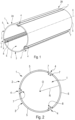
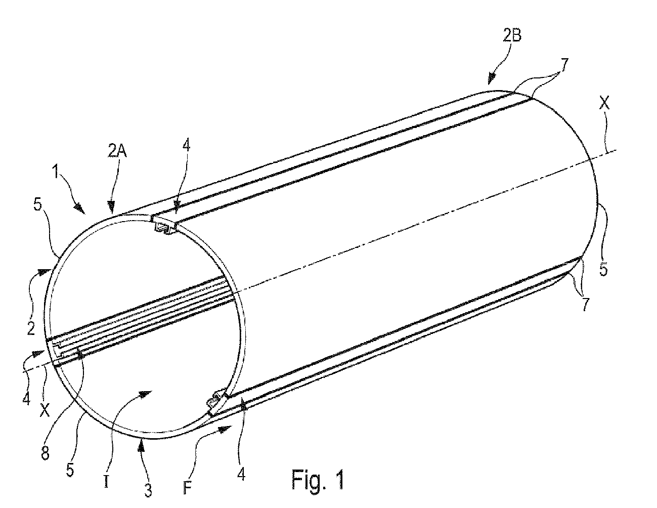
- the tank 1 comprises a central section 2 of cylindrical shape, representing a ferrule, of longitudinal axis XX.
- This central section 2 has a wall 3.
- the tank 1 can also comprise two domes 26A, 26B ( picture 3 ) each of which is mounted in the usual way at one of the ends 2A, 2B of the central section 2.
- the tank may comprise a central section having shapes other than a cylindrical shape, for example a conical shape or a shape with an oblong or arbitrary cross section.
- the shape of the tank can, in particular, be adapted to the space available for the arrangement of the liquid hydrogen tank, in particular when the latter is intended to equip a mobile machine, for example an aircraft.
- the tank 1 also comprises rails 4 which are integrated into the wall 3 of the central section 2 and are welded thereto, as specified below.
- the rails 4 are accessible from inside the tank 1.
- the central section 2 also comprises a plurality of elongated panels 5 (along the longitudinal axis XX), of curved (concave) shape in cross section.
- the curvature of each of the panels 5 corresponds to that of an arc of a circle with a radius equal to the radius R of the central section 2.
- the radius R defined between a central point O (located on the longitudinal axis XX) and the wall 3 has been represented.
- the panels 5 are identical, and between each pair of adjacent panels 5 is integrated a rail 4.
- the rails 4 are uniformly distributed transversely, namely equidistant from one rail to the neighboring rail.
- the central section 2 comprises three identical panels 5 and three rails 4 which are also identical.
- Each of the rails 4 comprises, as shown in the figure 4 , an elongated base 6.
- the base 6 preferably has a curved (concave) shape in cross section, with substantially the same curvature as that of the panels 5 of the central body 2.
- Each of the rails 4 is therefore welded to two adjacent panels 5.
- the rails 4 and the panels 5 are welded together via end-to-end longitudinal weld seams 7.
- this welding is carried out by means of friction stir welding of the FSW type (for “Friction Stir Welding”).
- FSW for “Friction Stir Welding”.
- other usual welding methods can also be used.
- Each of the rails 4 comprises a slide 8 on an internal face 9 of the base 6, as represented on the figure 4 .
- This slide 8, therefore accessible from inside the tank 1, is intended to allow movement by translation of connecting elements 16, as specified below.
- slider 8 comprises a housing 13 intended to receive a head 18 of a connecting element 16 and, as specified below, the housings 13 of the slides 8 of the rails 4 and the heads 18 of the connecting elements 16 have cooperating shapes.
- the slide 8 comprises two brackets 11 and 12 elongated.
- Each of these brackets 11 and 12 comprises a flat and elongated branch 11A, 12A, secured to the base 6, and a branch 11B, 12B (also flat and elongated) connected perpendicularly to the branch 11A, 12A respectively.
- the brackets 11 and 12 are arranged with their branches 11B and 12B facing each other so as to form a housing 13 provided with an opening 13A.
- brackets can be arranged in opposite directions, with their branches 11B and 12B moving away from each other.
- a connecting element of complementary shape is also provided.
- the brackets 11 and 12 can be inserts which are attached to the base 6. However, in a preferred embodiment, the brackets 11 and 12 and the base 6 form one and the same piece.
- each of these rails 4 is a profile, preferably extruded. It is thus possible to manufacture and use standard parts for the rails 4, which makes it possible in particular to reduce their manufacturing cost and therefore that of the tank 1.
- the longitudinal ends of the rails 4 are chamfered to facilitate the welding of the domes which are fixed to the ends of the tank 1 to close it.
- the tank 1 comprises a plurality of frames 14, such as that shown in the figure 5 .
- Each of these frames 14 corresponds to a disk, with a diameter slightly smaller than that of the tank 1, as specified below.
- This disc is provided with passage openings 15A, 15B and 15C, of various shapes and sizes.
- the passage openings 15A and 15B can be intended (if necessary) for the passage of equipment.
- the 15C passage openings of larger sizes they allow the passage of the fluid (liquid hydrogen) so as to confer an anti-sloshing function on the frame 14.
- Each of the frames 14 is capable of being mounted transversely in the tank 1, preferably so that the disc forming the frame 14 is arranged orthogonally to the longitudinal axis X-X.
- Each of the frames 14 is mounted in the tank 1 by being linked to the rails 4.
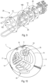
- a plurality of connecting elements 16 are provided, such as that represented on the figures 6 and 7 , which are intended to allow the connection of the frames 14 to the rails 4.
- Each of the connecting elements 16 is fixed to a frame 14 by one 16A of its ends 16A, 16B.
- the end 16A is provided with two flat and identical branches 17A and 17B, which are arranged side by side in parallel so as to create a free space 18 into which an edge of the frame 14 is inserted.
- the end 16A of the connecting element 16 is fixed to the frame 14, preferably by welding.
- each of the connecting elements 16 is provided, at the other end 16B, with a head 18 capable of being able to slide in the rail 4 while being held there.
- the heads 18 of the connecting elements 16 and the housings 13 ( figure 4 ) of the slides 8 of the rails 4, intended to receive these heads 18, have cooperating shapes.
- cooperating shapes is meant identical shapes, but with a size of the contour of the head 18 slightly smaller than that of the housing 13 so as to allow movement by translation of the head 18 in the housing 13, while being held there.
- the head 18 and the housing 13 have a rectangular shape in cross section. Cooperating shapes other than a rectangular shape can of course be provided for the heads 18 and the housings 13.
- the ends 16A and 16B of the connecting element 16 are linked together via a tab 20 ( figure 6 ) to form two lateral grooves 21 and 22.
- branches 11A and 11B of brackets 11 and 12 penetrate, respectively, in the side grooves 21 and 22, which ensures good stability.
- the tank 1 comprises a module 24 formed of a plurality of frames 14 linked together by means of equipment 25, in particular pipes, sensors, a cooling finger, ..., as specified below.
- This module 24 is able to be inserted into the tank 1, as shown in the picture 3 and specified below, via the connecting elements 16 and the rails 4.
- a process for manufacturing and assembling the tank 1, as described above, of the tank 10 for liquid hydrogen is specified below.
- the manufacturing step E1 consists in manufacturing a tank 1 comprising a central section 2 provided with integrated rails 4 ( figure 1 ). To do this, panels 5 and rails 4 are used, preferably of standard shape, which are arranged alternately, and each rail 4 is welded on either side to a panel 5 so as to obtain the 2 central section with integrated 4 rails.
- the mounting step E2 consists, for its part, in mounting equipment 25 in a plurality of frames 14 arranged side by side and provided with connecting elements 16, so as to form a module 24, as shown in the figure 9 .
- the equipment that is identified by a general reference relates to all of the equipment that must be arranged inside the tank 1 and which is necessary for its operation, as the internal tank of a liquid hydrogen tank 10 .
- These are mainly pipes (or pipes).
- part of the equipment 25, in particular pipes is passed through some of the passage openings 15A and 15B of the frames 14, and more precisely in particular individual pipes through the passage openings 15A of reduced diameter and pipe bundles through the passage openings 15B of larger diameter.
- the equipment 25 comprises pipes, sensors, a cooling finger, etc., and in particular all the usual elements necessary to generate the low temperatures required for the storage of liquid hydrogen.
- This assembly step E2 is carried out outside the tank 1, which makes it possible to remedy the accessibility constraints existing in the tank 1.
- Each of the frames 14 of the module 24 is also provided with connecting elements 16 of the same number as the number of rails of the tank 1. These connecting elements 16 are fixed by their end 16A to the frame 14 and they are positioned on the periphery of the frame 14 so as to be able to be introduced into the slides 8 of the rails 4 when the module 24 is mounted in the tank 1.
- the following insertion step E3 consists of inserting the module 24 (as a unitary assembly) into the central section 2 of the tank 1, from one of the ends 2A, 2B ( figure 1 ) of the central section 2. This insertion is carried out by a translation of the module 24 via a sliding of the heads 18 of the connecting elements 16 in the slides 8 of the rails 4.
- the fixing step E4 is implemented, for its part, after the insertion step E3 when the module 24 is completely inserted (or installed) and is in its final position in the tank 1, as represented on the figure 10 .
- the fixing step E4 consists in holding the module 24 in position by any type of known means and for example by fixing the heads 18 of the connecting elements 16 to the rails 4.
- the heads 18 of the connecting elements 16 are welded to the rails 4.
- Various usual welding methods can be used to carry out this welding, and in particular friction stir welding of the FSW type (for “Friction Stir Welding” in English) or a linear friction welding of the LFW type (for “Linear Friction Welding” in English).
- a locking or locking system is provided for locking the heads 18 of the connecting elements 16 in the rails 4.
- the locking system may comprise, for each connecting element , a pin which is provided on the head of the connecting element, which is elastically constrained, and which is configured to penetrate into an orifice made in the rail, when the frame (on which the connecting element is fixed) arrives in its final position, during the insertion of the module in the central section.
- one of the panels 5 of the tank 1 is removed, to allow a view of the interior of the tank 1 and in particular the module 24 provided with the frames 14 and the equipment 25, which is installed there.
- the assembly process for obtaining a vessel 1 for a liquid hydrogen tank 10, for example as shown in the picture 3 comprises other steps, for example a step of fixing domes on the central section, which do not fall within the scope of the present invention and are not described further.
Landscapes
- Engineering & Computer Science (AREA)
- Mechanical Engineering (AREA)
- General Engineering & Computer Science (AREA)
- Filling Or Discharging Of Gas Storage Vessels (AREA)
Abstract
- Cuve, en particulier pour réservoir à hydrogène liquide, pourvue de rails internes pour la mise en place d'un module d'équipements.
- La cuve (1) comprend un tronçon central (2) pourvu d'une paroi (3), ainsi qu'au moins un rail (4) et de préférence une pluralité de rails (4), chacun des rails (4) étant intégré dans la paroi (3) du tronçon central (2) de la cuve (1) de manière à être accessible de l'intérieur de la cuve (1), de tels rails (4) permettant une intégration et une fixation facilitées d'un module comprenant des équipements à l'intérieur de la cuve (1), de manière à simplifier la fabrication et l'assemblage de la cuve (1).
- The tank (1) comprises a central section (2) provided with a wall (3), as well as at least one rail (4) and preferably a plurality of rails (4), each of the rails (4) being integrated into the wall (3) of the central section (2) of the tank (1) so as to be accessible from inside the tank (1), such rails (4) allowing easy integration and fixing of a module comprising equipment inside the tank (1), so as to simplify the manufacture and assembly of the tank (1).
Description
La présente invention concerne une cuve, en particulier pour réservoir à hydrogène liquide, ainsi qu'un réservoir à hydrogène liquide pourvu d'une telle cuve.The present invention relates to a tank, in particular for a liquid hydrogen tank, as well as a liquid hydrogen tank provided with such a tank.
L'hydrogène liquide étant un combustible écologique n'émettant pas de gaz à effet de serre, il est envisagé de développer son utilisation et de l'utiliser à l'avenir dans des domaines très variés et notamment sur des aéronefs, en particulier sur des avions de transport.Since liquid hydrogen is an ecological fuel that does not emit greenhouse gases, it is planned to develop its use and use it in the future in a wide variety of fields and in particular on aircraft, in particular on transport aircraft.
Dans une telle utilisation notamment, l'hydrogène liquide doit être stocké dans un réservoir approprié.In such a use in particular, the liquid hydrogen must be stored in a suitable tank.
De façon usuelle, un réservoir à hydrogène liquide comporte un assemblage complexe de structures et de systèmes, tels que des tuyaux, des capteurs, des parois anti-ballotement, qui sont montés dans une cuve (interne) du réservoir.Usually, a liquid hydrogen tank comprises a complex assembly of structures and systems, such as pipes, sensors, anti-sloshing walls, which are mounted in an (internal) tank of the tank.
Tous ces éléments doivent être attachés à la structure interne de la cuve par l'intermédiaire de pattes de fixation. Un tel assemblage nécessite ainsi un nombre très élevé de pattes de fixation qui sont, généralement, toutes soudées à la paroi interne de la cuve.All these elements must be attached to the internal structure of the tank by means of fixing lugs. Such an assembly thus requires a very large number of fixing lugs which are generally all welded to the internal wall of the vessel.
En raison, de fortes contraintes d'accessibilité, ces opérations de fixation et de soudage sont très difficiles à réaliser, et l'assemblage de ces éléments est long et difficile à mettre en œuvre.Due to strong accessibility constraints, these fixing and welding operations are very difficult to perform, and the assembly of these elements is long and difficult to implement.
La présente invention concerne une cuve, en particulier pour réservoir à hydrogène liquide, ladite cuve comprenant un tronçon central pourvu d'une paroi, qui a pour objet de remédier à ces inconvénients.The present invention relates to a tank, in particular for a liquid hydrogen tank, said tank comprising a central section provided with a wall, the object of which is to overcome these drawbacks.
Selon l'invention, ladite cuve comporte au moins un rail, ledit rail étant intégré dans la paroi du tronçon central de la cuve de manière à être accessible de l'intérieur de la cuve. De préférence, ledit rail est soudé à ladite paroi.According to the invention, said tank comprises at least one rail, said rail being integrated into the wall of the central section of the tank so as to be accessible from inside the tank. Preferably, said rail is welded to said wall.
Ainsi, grâce à l'invention, on intègre un ou plusieurs rails dans la paroi de la cuve. De tels rails permettent une insertion et une fixation facilitées à l'intérieur de la cuve d'un module comprenant l'ensemble des équipements, comme précisé ci-dessous, ce qui permet notamment de remédier aux contraintes d'accessibilité et de simplifier la fabrication et l'assemblage de la cuve.Thus, thanks to the invention, one or more rails are integrated into the wall of the tank. Such rails allow easy insertion and fixing inside the tank of a module comprising all the equipment, as specified below, which makes it possible in particular to remedy accessibility constraints and simplify manufacturing. and assembly of the tank.
Avantageusement, le rail est pourvu sur une face interne d'une glissière destinée à recevoir au moins un élément de liaison, ladite glissière permettant un déplacement par translation du ou des éléments de liaison.Advantageously, the rail is provided on an internal face with a slide intended to receive at least one connecting element, said slide allowing movement by translation of the connecting element or elements.
En outre de façon avantageuse, la cuve comporte une pluralité de rails longitudinaux intégrés dans la paroi du tronçon central en étant orientés de manière à présenter des directions parallèles entre elles.In addition, advantageously, the tank comprises a plurality of longitudinal rails integrated into the wall of the central section, being oriented so as to present directions parallel to each other.
Par ailleurs, avantageusement, la cuve comporte au moins un cadre pourvu d'ouvertures de passage, apte à être agencé transversalement dans la cuve, en étant monté sur les rails.Furthermore, advantageously, the tank comprises at least one frame provided with passage openings, adapted to be arranged transversely in the tank, being mounted on the rails.
Dans un mode de réalisation particulier, la cuve comporte une pluralité d'éléments de liaison, chacun desdits éléments de liaison étant fixé au cadre par l'une de ses extrémités et étant pourvu à l'autre extrémité d'une tête apte à pouvoir glisser en coopérant avec le rail et à pouvoir être fixée avec le rail.In a particular embodiment, the tank comprises a plurality of connecting elements, each of said connecting elements being fixed to the frame by one of its ends and being provided at the other end with a head adapted to be able to slide by cooperating with the rail and being able to be fixed with the rail.
Dans un mode de réalisation préféré, la cuve comporte un module formé d'une pluralité de cadres liés ensemble par l'intermédiaire d'équipements, ledit module étant apte à être agencé dans la cuve, en étant monté sur les rails.In a preferred embodiment, the tank comprises a module formed of a plurality of frames linked together by means of equipment, said module being able to be arranged in the tank, by being mounted on the rails.
La présente invention concerne également un réservoir à hydrogène liquide, qui comporte une cuve telle que celle décrite ci-dessus.The present invention also relates to a liquid hydrogen tank, which comprises a tank such as that described above.
La présente invention concerne, en outre, un procédé de fabrication et d'assemblage d'une cuve telle que celle décrite ci-dessus ou d'un réservoir à hydrogène liquide tel que précité.The present invention also relates to a method for manufacturing and assembling a tank such as that described above or a liquid hydrogen tank as mentioned above.
Selon l'invention, ledit procédé comporte au moins les étapes suivantes :
- une étape de fabrication consistant à fabriquer une cuve pourvue d'un tronçon central, ledit tronçon central présentant une paroi dans laquelle sont intégrés des rails ;
- une étape de montage consistant à monter des équipements dans une pluralité de cadres disposés côte à côte et pourvus d'éléments de liaison, de manière à former un module ;
- une étape d'insertion consistant à insérer le module dans la cuve par coulissement de têtes des éléments de liaison dans les rails ; et
- une étape de fixation consistant, dans une position montée du module dans la cuve, à maintenir le module en position.
- a manufacturing step consisting in manufacturing a tank provided with a central section, said central section having a wall in which rails are integrated;
- an assembly step consisting in mounting equipment in a plurality of frames arranged side by side and provided with connecting elements, so as to form a module;
- an insertion step consisting of inserting the module into the tank by sliding the heads of the connecting elements in the rails; And
- a fixing step consisting, in a mounted position of the module in the tank, of holding the module in position.
De préférence, l'étape de fixation consiste, pour maintenir le module en position, à fixer les têtes des éléments de liaison aux rails.Preferably, the fixing step consists, in order to hold the module in position, in fixing the heads of the connecting elements to the rails.
Les figures annexées feront bien comprendre comment l'invention peut être réalisée. Sur ces figures, des références identiques désignent des éléments semblables.
- La
figure 1 est une vue schématique, en perspective, d'un mode de réalisation particulier du tronçon central d'une cuve pourvue de rails. - La
figure 2 est une vue transversale schématique de la cuve de lafigure 1 . - La
figure 3 est une vue schématique, en perspective, d'un mode de réalisation particulier d'un réservoir à hydrogène liquide, partiellement ouvert pour en visualiser l'intérieur. - La
figure 4 est une vue schématique, en coupe, d'une partie d'un tronçon central d'une cuve, pourvue d'un rail. - La
figure 5 est une vue transversale schématique d'une cuve pourvu d'un cadre. - La
figure 6 est une vue, en perspective, d'un élément de liaison. - La
figure 7 est une vue schématique, en coupe, d'un élément de liaison liant un cadre montré partiellement à un rail. - La
figure 8 montre schématiquement les étapes principales d'un procédé de fabrication et d'assemblage d'une cuve. - La
figure 9 est une vue, en perspective, d'un module pourvu de cadres et d'équipements. - La
figure 10 est une vue, en perspective, d'une cuve dans laquelle est monté un module pourvu de cadres et d'équipements.
- There
figure 1 is a schematic view, in perspective, of a particular embodiment of the central section of a tank provided with rails. - There
figure 2 is a schematic cross-sectional view of the tank of thefigure 1 . - There
picture 3 is a schematic view, in perspective, of a particular embodiment of a liquid hydrogen tank, partially open to view the interior. - There
figure 4 is a schematic view, in section, of part of a central section of a tank, provided with a rail. - There
figure 5 is a schematic cross-sectional view of a tank provided with a frame. - There
figure 6 is a perspective view of a connecting element. - There
figure 7 is a schematic view, in section, of a connecting element connecting a frame shown partially to a rail. - There
figure 8 schematically shows the main stages of a tank manufacturing and assembly process. - There
figure 9 is a view, in perspective, of a module provided with frames and equipment. - There
figure 10 is a view, in perspective, of a tank in which is mounted a module provided with frames and equipment.
La cuve 1 permettant d'illustrer l'invention et représentée schématiquement et partiellement dans un mode de réalisation particulier sur les
De façon usuelle, un tel réservoir 10 à hydrogène liquide comporte généralement, en plus de la cuve 1 qui est une cuve interne, une seconde cuve dite cuve externe (non représentée). La cuve interne est montée dans la cuve externe, et elle comprend des équipements fonctionnels précisés ci-dessous.Usually, such a
Bien que non exclusivement, un réservoir 10 à hydrogène liquide est particulièrement bien adapté pour équiper un engin mobile fonctionnant, au moins partiellement, à l'hydrogène. De manière préférée, le réservoir 10 est destiné à équiper un aéronef, en particulier un avion de transport.Although not exclusively, a
Dans le mode de réalisation préféré, représenté sur les
Dans le cadre de la présente invention, la cuve peut comprendre un tronçon central présentant des formes autres qu'une forme cylindrique, par exemple une forme conique ou une forme avec une section transversale oblongue ou quelconque. La forme de la cuve peut, notamment, être adaptée à l'espace disponible pour l'agencement du réservoir à hydrogène liquide, en particulier lorsque ce dernier est destiné à équiper un engin mobile, par exemple un aéronef.In the context of the present invention, the tank may comprise a central section having shapes other than a cylindrical shape, for example a conical shape or a shape with an oblong or arbitrary cross section. The shape of the tank can, in particular, be adapted to the space available for the arrangement of the liquid hydrogen tank, in particular when the latter is intended to equip a mobile machine, for example an aircraft.
La cuve 1 comprend également des rails 4 qui sont intégrés dans la paroi 3 du tronçon central 2 et y sont soudés, comme précisé ci-dessous. Les rails 4 sont accessibles de l'intérieur de la cuve 1.The
Dans la description suivante :
- les termes « interne » et « intérieur » s'appliquent à l'espace entouré et délimité par la paroi 3 de la cuve 1, comme illustré par une flèche I sur la
figure 1 ; et - les termes « externe » et « extérieur » s'appliquent à ce qui est hors de l'espace entouré par la paroi 3 de la cuve 1, comme illustré par une flèche F sur la
figure 1 .
- the terms “internal” and “interior” apply to the space surrounded and delimited by the wall 3 of the
tank 1, as illustrated by an arrow I on thefigure 1 ; And - the terms “external” and “external” apply to what is outside the space surrounded by the wall 3 of the
tank 1, as illustrated by an arrow F on thefigure 1 .
Le tronçon central 2 comprend, également, une pluralité de panneaux 5 allongés (selon l'axe longitudinal X-X), de forme courbe (concave) en section transversale. La courbure de chacun des panneaux 5 correspond à celle d'un arc de cercle de rayon égal au rayon R du tronçon central 2. Sur la
Dans un mode de réalisation particulier, les panneaux 5 sont identiques, et entre chaque paire de panneaux 5 adjacents est intégré un rail 4.In a particular embodiment, the
En outre, dans un mode de réalisation particulier, les rails 4 sont répartis transversalement uniformément, à savoir à équidistance d'un rail au rail voisin.In addition, in a particular embodiment, the
Dans le mode de réalisation représenté sur les
Chacun des rails 4 comprend, comme représenté sur la
Chacun des rails 4 est donc soudé à deux panneaux 5 adjacents. Les rails 4 et les panneaux 5 sont soudés ensemble par l'intermédiaire de cordons de soudure 7 longitudinaux bout-à-bout.Each of the
De préférence, ce soudage est réalisé par l'intermédiaire d'un soudage par friction malaxage de type FSW (pour « Friction Stir Welding » en anglais). Dans le cadre de la présente invention, d'autres méthodes de soudage usuelles peuvent également être employées.Preferably, this welding is carried out by means of friction stir welding of the FSW type (for “Friction Stir Welding”). In the context of the present invention, other usual welding methods can also be used.
Chacun des rails 4 comprend une glissière 8 sur une face interne 9 de la base 6, comme représenté sur la
Dans le mode de réalisation de la
Dans une variante de réalisation (non représentée), les équerres peuvent être agencées en sens opposés, avec leurs branches 11B et 12B s'éloignant l'une de l'autre. Dans cette variante, on prévoit également un élément de liaison de forme complémentaire.In a variant embodiment (not shown), the brackets can be arranged in opposite directions, with their
Les équerres 11 et 12 peuvent être des pièces rapportées qui sont fixées sur la base 6. Toutefois, dans un mode de réalisation préféré, les équerres 11 et 12 et la base 6 forment une seule et même pièce.The
Dans un mode de réalisation particulier, chacun de ces rails 4 est un profilé, de préférence extrudé. On est ainsi en mesure de fabriquer et d'utiliser des pièces standard pour les rails 4, ce qui permet notamment de réduire leur coût de fabrication et donc celui de la cuve 1.In a particular embodiment, each of these
Dans un mode de réalisation particulier (non représenté), les extrémités longitudinales des rails 4 sont chanfreinées pour faciliter le soudage des dômes qui sont fixés aux extrémités de la cuve 1 pour la fermer.In a particular embodiment (not shown), the longitudinal ends of the
Par ailleurs, la cuve 1 comporte une pluralité de cadres 14, tel que celui montré sur la
Chacun de ces cadres 14 correspond à un disque, de diamètre légèrement inférieur à celui de la cuve 1, comme précisé ci-dessous. Ce disque est pourvu d'ouvertures de passage 15A, 15B et 15C, de formes et de tailles variées. Dans l'exemple représenté sur la
Chacun des cadres 14 est apte à être monté transversalement dans la cuve 1, de préférence de sorte que le disque formant le cadre 14 soit agencé orthogonalement à l'axe longitudinal X-X.Each of the
Chacun des cadres 14 est monté dans la cuve 1 en étant lié aux rails 4. Pour ce faire, on prévoit une pluralité d'éléments de liaison 16, tels que celui représenté sur les
Chacun des éléments de liaison 16 est fixé à un cadre 14 par l'une 16A de ses extrémités 16A, 16B. Dans un mode de réalisation particulier, l'extrémité 16A est pourvue de deux branches 17A et 17B planes et identiques, qui sont agencées côte à côte en parallèle de manière à créer un espace libre 18 dans lequel est insérée un bord du cadre 14. Dans ce cas, comme représenté sur la
De plus, chacun des éléments de liaison 16 est pourvu, à l'autre extrémité 16B, d'une tête 18 apte à pouvoir glisser dans le rail 4 en y étant maintenue.In addition, each of the connecting
Les têtes 18 des éléments de liaison 16 et les logements 13 (
Dans l'exemple représenté sur les
Les extrémités 16A et 16B de l'élément de liaison 16 sont liées ensemble par l'intermédiaire d'une languette 20 (
Dans un mode de réalisation préféré, la cuve 1 comporte un module 24 formé d'une pluralité de cadres 14 liés ensemble par l'intermédiaire d'équipements 25, notamment des tuyaux, des capteurs, un doigt réfrigérant,..., comme précisé ci-dessous. Ce module 24 est apte à être inséré dans la cuve 1, comme représenté sur la
Les cadres 14, tels que décrits ci-dessus, présentent de nombreux avantages. En effet, chacun des cadres 14 utilisés, fabriqués par exemple en aluminium, réalise l'ensemble des fonctions suivantes :
- il sert de support à tous les équipements 25 précisés ci-dessous, à l'intérieur de la cuve 1, ce qui permet de supprimer toutes les fixations usuelles ;
- il peut agir comme cadre anti-ballottement, ce qui permet de supprimer les parois anti-ballottement usuelles ; et
- il participe à l'obtention de la stabilité structurelle du
module 24.
- it serves as a support for all the
equipment 25 specified below, inside thetank 1, which makes it possible to eliminate all the usual fasteners; - it can act as an anti-sway frame, which makes it possible to eliminate the usual anti-sway walls; And
- it participates in obtaining the structural stability of
module 24.
On précise, ci-après, un procédé de fabrication et d'assemblage de la cuve 1, telle que décrite ci-dessus, du réservoir 10 à hydrogène liquide.A process for manufacturing and assembling the
Ce procédé P de fabrication et d'assemblage comporte, comme représenté sur la
- une étape de fabrication E1 ;
- une étape de montage E2 ;
- une étape d'insertion E3 ; et
- une étape de fixation E4.
- a manufacturing step E1;
- an assembly step E2;
- an insertion step E3; And
- a fixing step E4.
L'étape de fabrication E1 consiste à fabriquer une cuve 1 comprenant un tronçon central 2 pourvu de rails 4 intégrés (
A cette étape de fabrication E1, diverses méthodes de soudage usuelles peuvent être employées pour souder les rails 4 aux panneaux 5. Toutefois, de préférence, ce soudage est réalisé par l'intermédiaire d'un soudage par friction malaxage de type FSW (pour « Friction Stir Welding » en anglais).At this manufacturing step E1, various usual welding methods can be used to weld the
L'étape de montage E2 consiste, quant à elle, à monter des équipements 25 dans une pluralité de cadres 14 disposés côte à côte et pourvus d'éléments de liaison 16, de manière à former un module 24, comme représenté sur la
Les équipements qui sont identifiés par une référence 25 générale concernent l'ensemble des équipements qui doivent être agencés à l'intérieur de la cuve 1 et qui sont nécessaires à son fonctionnement, en tant que cuve interne d'un réservoir 10 à hydrogène liquide. Il s'agit principalement de tuyaux (ou conduites). Pour ce faire, on fait traverser une partie des équipements 25, en particulier des tuyaux, à travers certaines des ouvertures de passage 15A et 15B des cadres 14, et plus précisément notamment des tuyaux individuels à travers les ouvertures de passage 15A de diamètre réduit et des faisceaux de tuyaux à travers les ouvertures de passage 15B de diamètre plus important.The equipment that is identified by a general reference relates to all of the equipment that must be arranged inside the
A titre d'illustration, non limitative, les équipements 25 comprennent des tuyaux, des capteurs, un doigt réfrigérant, ..., et notamment tous les éléments usuels nécessaires pour générer les basses températures requises pour le stockage de l'hydrogène liquide.By way of non-limiting illustration, the
Cette étape de montage E2 est réalisée à l'extérieur de la cuve 1, ce qui permet de remédier aux contraintes d'accessibilité existant dans la cuve 1.This assembly step E2 is carried out outside the
A la fin de l'étape de montage E2, on obtient grâce auxdits cadres 14 et aux équipements 25 qui traversent les cadres 14, un module 24 présentant une stabilité structurelle permettant son déplacement.At the end of the assembly step E2, thanks to said
Chacun des cadres 14 du module 24 est également pourvu d'éléments de liaison 16 de même nombre que le nombre de rails de la cuve 1. Ces éléments de liaison 16 sont fixés par leur extrémité 16A au cadre 14 et ils sont positionnés en périphérie du cadre 14 de manière à pouvoir être introduits dans les glissières 8 des rails 4 lorsque le module 24 est monté dans la cuve 1.Each of the
L'étape d'insertion E3 qui suit consiste à insérer le module 24 (en tant qu'ensemble unitaire) dans le tronçon central 2 de la cuve 1, à partir de l'une des extrémités 2A, 2B (
L'étape de fixation E4 est mise en œuvre, quant à elle, après l'étape d'insertion E3 lorsque le module 24 est complètement inséré (ou installé) et se trouve dans sa position définitive dans la cuve 1, comme représenté sur la
Pour ce faire, dans un premier mode de réalisation, les têtes 18 des éléments de liaison 16 sont soudées aux rails 4. Diverses méthodes de soudage usuelles peuvent être employées pour réaliser ce soudage, et notamment un soudage par friction malaxage de type FSW (pour « Friction Stir Welding » en anglais) ou un soudage par friction linéaire de type LFW (pour « Linear Friction Welding » en anglais).To do this, in a first embodiment, the
Dans un second mode de réalisation, on prévoit un système de blocage ou de verrouillage permettant de bloquer les têtes 18 des éléments de liaison 16 dans les rails 4. A titre d'exemple, le système de blocage peut comporter, pour chaque élément de liaison, un pion qui est prévu sur la tête de l'élément de liaison, qui est contraint élastiquement, et qui est configuré pour pénétrer dans un orifice pratiqué dans le rail, lorsque le cadre (sur lequel est fixé l'élément de liaison) arrive dans sa position définitive, au cours de l'insertion du module dans le tronçon central.In a second embodiment, a locking or locking system is provided for locking the
Sur la représentation de la
Le procédé d'assemblage pour obtenir une cuve 1 pour un réservoir 10 à hydrogène liquide, par exemple tel que représenté sur la
La présente invention présente de nombreux avantages, et en particulier les avantages suivants :
- une simplification de la fabrication et de l'assemblage de la cuve 1, qui représente de préférence une cuve interne d'un réservoir 10 à hydrogène liquide, notamment pour les raisons suivantes :
- l'assemblage des équipements dans un
unique module 24 et l'insertion dans la cuve de cetunique module 24 ; - l'utilisation d'un nombre restreint de pièces et la possibilité de standardiser les principales pièces utilisées, à savoir principalement les panneaux 5, les rails 4, les
cadres 14 et les éléments deliaison 16 ; - un nombre réduit de points d'interface et la suppression de toutes les pattes de fixation usuelles ;
- la suppression de parois anti-ballottement ; et
- l'assemblage des équipements dans un
- les caractéristiques de l'invention peuvent être adaptées à des cuves de tailles et de configurations variées.
- a simplification of the manufacture and assembly of the
tank 1, which preferably represents an internal tank of aliquid hydrogen tank 10, in particular for the following reasons:- assembling the equipment in a
single module 24 and inserting thissingle module 24 into the tank; - the use of a limited number of parts and the possibility of standardizing the main parts used, namely mainly the
panels 5, therails 4, theframes 14 and the connectingelements 16; - a reduced number of interface points and the elimination of all the usual mounting brackets;
- the removal of anti-sloshing walls; And
- assembling the equipment in a
- the characteristics of the invention can be adapted to tanks of various sizes and configurations.
Claims (9)
caractérisée en ce qu'elle comporte au moins un rail (4), ledit rail (4) étant intégré dans la paroi (3) du tronçon central (2) de la cuve (1) de manière à être accessible de l'intérieur de la cuve (1), ledit rail (4) étant pourvu sur une face interne (9) d'une glissière (8) destinée à recevoir au moins un élément de liaison (16), ladite glissière (8) permettant un déplacement par translation du ou des éléments de liaison (16).Tank, in particular for a liquid hydrogen tank, said tank (1) comprising a central section (2) provided with a wall (3),
characterized in that it comprises at least one rail (4), said rail (4) being integrated into the wall (3) of the central section (2) of the tank (1) so as to be accessible from the inside of the tank (1), said rail (4) being provided on an internal face (9) with a slide (8) intended to receive at least one connecting element (16), said slide (8) allowing movement by translation of the connecting element(s) (16).
caractérisée en ce que le rail (4) est soudé à la paroi (3) du tronçon central (2) de la cuve (1).Tank according to claim 1,
characterized in that the rail (4) is welded to the wall (3) of the central section (2) of the tank (1).
caractérisée en ce qu'elle comporte une pluralité de rails (4) longitudinaux intégrés dans la paroi (3) du tronçon central (2) en étant orientés de manière à présenter des directions parallèles entre elles.Tank according to any one of claims 1 and 2,
characterized in that it comprises a plurality of longitudinal rails (4) integrated in the wall (3) of the central section (2) being oriented so as to present directions parallel to each other.
caractérisée en ce qu'elle comporte au moins un cadre (14) pourvu d'ouvertures de passage (15A, 15B, 15C), apte à être agencé transversalement dans la cuve (1), en étant monté sur les rails (4).Tank according to any one of claims 1 to 3,
characterized in that it comprises at least one frame (14) provided with passage openings (15A, 15B, 15C), adapted to be arranged transversely in the tank (1), being mounted on the rails (4).
caractérisée en ce qu'elle comporte une pluralité d'éléments de liaison (16), chacun desdits éléments de liaison (16) étant fixé au cadre (14) par l'une (16A) de ses extrémités et étant pourvu à l'autre extrémité (16B) d'une tête (18) apte à pouvoir glisser en coopérant avec le rail (4) et à pouvoir être fixée avec le rail (4).Tank according to claim 4,
characterized in that it comprises a plurality of connecting elements (16), each of said connecting elements (16) being fixed to the frame (14) by one (16A) of its ends and being provided at the other end (16B) of a head (18) adapted to be able to slide by cooperating with the rail (4) and to be able to be fixed with the rail (4).
caractérisée en ce qu'elle comporte un module (24) formé d'une pluralité de cadres (14) liés ensemble par l'intermédiaire d'équipements (25), ledit module (24) étant apte à être agencé dans la cuve (1), en étant monté sur les rails (4).Tank according to any one of claims 4 or 5,
characterized in that it comprises a module (24) formed of a plurality of frames (14) linked together by means of equipment (25), said module (24) being able to be arranged in the tank (1 ), being mounted on the rails (4).
caractérisé en ce qu'il comporte une cuve (1) selon l'une quelconque des revendications 1 à 6.Tank for liquid hydrogen,
characterized in that it comprises a tank (1) according to any one of claims 1 to 6.
caractérisé en ce qu'il comporte au moins les étapes suivantes :
characterized in that it comprises at least the following steps:
caractérisé en ce que l'étape de fixation (E4) consiste, pour maintenir le module (24) en position, à fixer les têtes (18) des éléments de liaison (16) aux rails (4).Method according to claim 8,
characterized in that the fixing step (E4) consists, in order to hold the module (24) in position, in fixing the heads (18) of the connecting elements (16) to the rails (4).
Applications Claiming Priority (1)
| Application Number | Priority Date | Filing Date | Title |
|---|---|---|---|
| FR2108276A FR3125857A1 (en) | 2021-07-29 | 2021-07-29 | Tank, in particular for liquid hydrogen tank, provided with internal rails for the installation of an equipment module. |
Publications (1)
| Publication Number | Publication Date |
|---|---|
| EP4124792A1 true EP4124792A1 (en) | 2023-02-01 |
Family
ID=77999137
Family Applications (1)
| Application Number | Title | Priority Date | Filing Date |
|---|---|---|---|
| EP22184514.2A Pending EP4124792A1 (en) | 2021-07-29 | 2022-07-12 | Vat, in particular for a tank with liquid hydrogen, provided with internal rails for fitting an equipment module |
Country Status (4)
| Country | Link |
|---|---|
| US (1) | US12486947B2 (en) |
| EP (1) | EP4124792A1 (en) |
| CN (1) | CN115681794A (en) |
| FR (1) | FR3125857A1 (en) |
Families Citing this family (1)
| Publication number | Priority date | Publication date | Assignee | Title |
|---|---|---|---|---|
| US20250333185A1 (en) * | 2024-04-30 | 2025-10-30 | Airbus Operations Sas | Method for mounting a hydrogen box in a for a hydrogen-powered aircraft |
Citations (5)
| Publication number | Priority date | Publication date | Assignee | Title |
|---|---|---|---|---|
| US2860809A (en) * | 1957-02-14 | 1958-11-18 | Skyline Products Inc | Tank baffle |
| WO2005085099A1 (en) * | 2004-03-10 | 2005-09-15 | Aker Finnyards Oy | A method of planning and manufacturing an lng storage tank or the like and an aluminium lng storage tank manufactured using the method |
| WO2012065616A1 (en) * | 2010-11-16 | 2012-05-24 | Nordic Yards Wismar Gmbh | Tank for transporting and/or storing cryogenic liquids |
| US20180066796A1 (en) * | 2016-09-02 | 2018-03-08 | AccuAir Control Systems, LLC | Systems, devices and methods for modular pressure vessels |
| EP3421864A1 (en) * | 2017-06-26 | 2019-01-02 | Ateliers et Chantiers de la Grande Bruyere (ACGB) | Liquefied natural gas tank for motor vehicles |
Family Cites Families (5)
| Publication number | Priority date | Publication date | Assignee | Title |
|---|---|---|---|---|
| US3235344A (en) * | 1963-02-18 | 1966-02-15 | Chevron Res | Hydrocarbon conversion catalytic reactor |
| JP4078522B2 (en) * | 2002-01-31 | 2008-04-23 | Jfeスチール株式会社 | Hybrid hydrogen storage container and method for storing hydrogen in the container |
| CN110701478B (en) * | 2019-11-18 | 2025-02-07 | 大连大学 | Metal hydride hydrogen storage container with easy disassembly and effective heat exchange |
| CN111256032A (en) * | 2020-01-17 | 2020-06-09 | 缪岩杉 | Leak-free processor for dead bottles of highly toxic media |
| GB2596808B (en) * | 2020-07-06 | 2023-12-06 | Bae Systems Plc | A method of manufacturing a pressure vessel |
-
2021
- 2021-07-29 FR FR2108276A patent/FR3125857A1/en not_active Ceased
-
2022
- 2022-07-12 EP EP22184514.2A patent/EP4124792A1/en active Pending
- 2022-07-25 US US17/872,311 patent/US12486947B2/en active Active
- 2022-07-29 CN CN202210909036.6A patent/CN115681794A/en active Pending
Patent Citations (5)
| Publication number | Priority date | Publication date | Assignee | Title |
|---|---|---|---|---|
| US2860809A (en) * | 1957-02-14 | 1958-11-18 | Skyline Products Inc | Tank baffle |
| WO2005085099A1 (en) * | 2004-03-10 | 2005-09-15 | Aker Finnyards Oy | A method of planning and manufacturing an lng storage tank or the like and an aluminium lng storage tank manufactured using the method |
| WO2012065616A1 (en) * | 2010-11-16 | 2012-05-24 | Nordic Yards Wismar Gmbh | Tank for transporting and/or storing cryogenic liquids |
| US20180066796A1 (en) * | 2016-09-02 | 2018-03-08 | AccuAir Control Systems, LLC | Systems, devices and methods for modular pressure vessels |
| EP3421864A1 (en) * | 2017-06-26 | 2019-01-02 | Ateliers et Chantiers de la Grande Bruyere (ACGB) | Liquefied natural gas tank for motor vehicles |
Also Published As
| Publication number | Publication date |
|---|---|
| FR3125857A1 (en) | 2023-02-03 |
| US12486947B2 (en) | 2025-12-02 |
| US20230036429A1 (en) | 2023-02-02 |
| CN115681794A (en) | 2023-02-03 |
Similar Documents
| Publication | Publication Date | Title |
|---|---|---|
| EP2304368B1 (en) | Heat exchanger and housing for the exchanger | |
| EP2491328B1 (en) | Heat exchanger header | |
| FR2680288A1 (en) | METHOD FOR MANUFACTURING A CONNECTOR SOCKET AND SAME. | |
| WO2010003807A1 (en) | Heat exchanger and casing for the heat exchanger | |
| FR2929458A1 (en) | DEVICE FOR FASTENING A WIRED CABLES PATH ON A THREADED ROD | |
| WO2008139097A2 (en) | Device for pre-stressed sealed connection with flanges | |
| EP4124792A1 (en) | Vat, in particular for a tank with liquid hydrogen, provided with internal rails for fitting an equipment module | |
| WO2010052194A1 (en) | Collector plate for a heat exchanger, and heat exchanger including such a plate | |
| FR2459546A1 (en) | FUSE BLOCK COVER | |
| EP1340290A1 (en) | Female contact having a cage structure comprising a blade-holder module | |
| EP2732517B1 (en) | Pivoting splice plate for connecting segments of a wire-based cable tray | |
| EP2260553A2 (en) | Device for attaching a plurality of cables grouped together | |
| EP4124791B1 (en) | Vat, in particular for a tank with liquid hydrogen, provided with at least one dome fixed by external welding | |
| FR3091493A1 (en) | Chain link | |
| EP0745532B1 (en) | A profile design for the assembly of a seating structure, specially an aircraft seat , and assembly process using this profile | |
| EP3001132A1 (en) | Method for manufacturing a heat exchanger | |
| FR3100587A1 (en) | FIXING DEVICE AND SYSTEM INCLUDING THIS FIXING DEVICE | |
| EP0197812B1 (en) | Heat exchanger having helically coiled tubes provided with means for tube supporting | |
| EP2471152B1 (en) | Comb flange for high-voltage cables | |
| FR2933179A1 (en) | Heat exchanger for use as charge air cooler in internal combustion heat engine of motor vehicle, has heat exchanging elements emerging into collector box via orifices of collector plate, where orifices are provided with stiffening units | |
| WO2006035149A1 (en) | Heat exchange insert for a heat exchange device | |
| EP3987591B1 (en) | Connecting means between two parts of a bus bar | |
| EP2123919A1 (en) | Rigid assembly of tubular parts | |
| EP4207506A1 (en) | Kit for an electrical connector and electrical connector | |
| FR2818028A1 (en) | Female electrical contact has parallelepiped cage with blade holder to receive plug |
Legal Events
| Date | Code | Title | Description |
|---|---|---|---|
| PUAI | Public reference made under article 153(3) epc to a published international application that has entered the european phase |
Free format text: ORIGINAL CODE: 0009012 |
|
| STAA | Information on the status of an ep patent application or granted ep patent |
Free format text: STATUS: THE APPLICATION HAS BEEN PUBLISHED |
|
| AK | Designated contracting states |
Kind code of ref document: A1 Designated state(s): AL AT BE BG CH CY CZ DE DK EE ES FI FR GB GR HR HU IE IS IT LI LT LU LV MC MK MT NL NO PL PT RO RS SE SI SK SM TR |
|
| STAA | Information on the status of an ep patent application or granted ep patent |
Free format text: STATUS: REQUEST FOR EXAMINATION WAS MADE |
|
| 17P | Request for examination filed |
Effective date: 20230707 |
|
| RBV | Designated contracting states (corrected) |
Designated state(s): AL AT BE BG CH CY CZ DE DK EE ES FI FR GB GR HR HU IE IS IT LI LT LU LV MC MK MT NL NO PL PT RO RS SE SI SK SM TR |
|
| STAA | Information on the status of an ep patent application or granted ep patent |
Free format text: STATUS: EXAMINATION IS IN PROGRESS |
|
| 17Q | First examination report despatched |
Effective date: 20250210 |