EP4124675A1 - Bruchstabile trennwand umfassend festelektrolytkeramiken für elektrolysezellen - Google Patents
Bruchstabile trennwand umfassend festelektrolytkeramiken für elektrolysezellen Download PDFInfo
- Publication number
- EP4124675A1 EP4124675A1 EP21188434.1A EP21188434A EP4124675A1 EP 4124675 A1 EP4124675 A1 EP 4124675A1 EP 21188434 A EP21188434 A EP 21188434A EP 4124675 A1 EP4124675 A1 EP 4124675A1
- Authority
- EP
- European Patent Office
- Prior art keywords
- sub
- electrolytic cell
- partition
- chamber
- solid electrolyte
- Prior art date
- Legal status (The legal status is an assumption and is not a legal conclusion. Google has not performed a legal analysis and makes no representation as to the accuracy of the status listed.)
- Granted
Links
Images




Classifications
-
- C—CHEMISTRY; METALLURGY
- C25—ELECTROLYTIC OR ELECTROPHORETIC PROCESSES; APPARATUS THEREFOR
- C25B—ELECTROLYTIC OR ELECTROPHORETIC PROCESSES FOR THE PRODUCTION OF COMPOUNDS OR NON-METALS; APPARATUS THEREFOR
- C25B13/00—Diaphragms; Spacing elements
- C25B13/02—Diaphragms; Spacing elements characterised by shape or form
-
- C—CHEMISTRY; METALLURGY
- C25—ELECTROLYTIC OR ELECTROPHORETIC PROCESSES; APPARATUS THEREFOR
- C25B—ELECTROLYTIC OR ELECTROPHORETIC PROCESSES FOR THE PRODUCTION OF COMPOUNDS OR NON-METALS; APPARATUS THEREFOR
- C25B13/00—Diaphragms; Spacing elements
- C25B13/04—Diaphragms; Spacing elements characterised by the material
- C25B13/05—Diaphragms; Spacing elements characterised by the material based on inorganic materials
- C25B13/07—Diaphragms; Spacing elements characterised by the material based on inorganic materials based on ceramics
-
- C—CHEMISTRY; METALLURGY
- C25—ELECTROLYTIC OR ELECTROPHORETIC PROCESSES; APPARATUS THEREFOR
- C25B—ELECTROLYTIC OR ELECTROPHORETIC PROCESSES FOR THE PRODUCTION OF COMPOUNDS OR NON-METALS; APPARATUS THEREFOR
- C25B3/00—Electrolytic production of organic compounds
- C25B3/01—Products
- C25B3/07—Oxygen containing compounds
-
- C—CHEMISTRY; METALLURGY
- C25—ELECTROLYTIC OR ELECTROPHORETIC PROCESSES; APPARATUS THEREFOR
- C25B—ELECTROLYTIC OR ELECTROPHORETIC PROCESSES FOR THE PRODUCTION OF COMPOUNDS OR NON-METALS; APPARATUS THEREFOR
- C25B3/00—Electrolytic production of organic compounds
- C25B3/01—Products
- C25B3/13—Organo-metallic compounds
-
- C—CHEMISTRY; METALLURGY
- C25—ELECTROLYTIC OR ELECTROPHORETIC PROCESSES; APPARATUS THEREFOR
- C25B—ELECTROLYTIC OR ELECTROPHORETIC PROCESSES FOR THE PRODUCTION OF COMPOUNDS OR NON-METALS; APPARATUS THEREFOR
- C25B3/00—Electrolytic production of organic compounds
- C25B3/20—Processes
- C25B3/25—Reduction
-
- C—CHEMISTRY; METALLURGY
- C25—ELECTROLYTIC OR ELECTROPHORETIC PROCESSES; APPARATUS THEREFOR
- C25B—ELECTROLYTIC OR ELECTROPHORETIC PROCESSES FOR THE PRODUCTION OF COMPOUNDS OR NON-METALS; APPARATUS THEREFOR
- C25B9/00—Cells or assemblies of cells; Constructional parts of cells; Assemblies of constructional parts, e.g. electrode-diaphragm assemblies; Process-related cell features
- C25B9/17—Cells comprising dimensionally-stable non-movable electrodes; Assemblies of constructional parts thereof
- C25B9/19—Cells comprising dimensionally-stable non-movable electrodes; Assemblies of constructional parts thereof with diaphragms
-
- C—CHEMISTRY; METALLURGY
- C25—ELECTROLYTIC OR ELECTROPHORETIC PROCESSES; APPARATUS THEREFOR
- C25B—ELECTROLYTIC OR ELECTROPHORETIC PROCESSES FOR THE PRODUCTION OF COMPOUNDS OR NON-METALS; APPARATUS THEREFOR
- C25B9/00—Cells or assemblies of cells; Constructional parts of cells; Assemblies of constructional parts, e.g. electrode-diaphragm assemblies; Process-related cell features
- C25B9/17—Cells comprising dimensionally-stable non-movable electrodes; Assemblies of constructional parts thereof
- C25B9/19—Cells comprising dimensionally-stable non-movable electrodes; Assemblies of constructional parts thereof with diaphragms
- C25B9/21—Cells comprising dimensionally-stable non-movable electrodes; Assemblies of constructional parts thereof with diaphragms two or more diaphragms
-
- C—CHEMISTRY; METALLURGY
- C25—ELECTROLYTIC OR ELECTROPHORETIC PROCESSES; APPARATUS THEREFOR
- C25B—ELECTROLYTIC OR ELECTROPHORETIC PROCESSES FOR THE PRODUCTION OF COMPOUNDS OR NON-METALS; APPARATUS THEREFOR
- C25B9/00—Cells or assemblies of cells; Constructional parts of cells; Assemblies of constructional parts, e.g. electrode-diaphragm assemblies; Process-related cell features
- C25B9/60—Constructional parts of cells
-
- Y—GENERAL TAGGING OF NEW TECHNOLOGICAL DEVELOPMENTS; GENERAL TAGGING OF CROSS-SECTIONAL TECHNOLOGIES SPANNING OVER SEVERAL SECTIONS OF THE IPC; TECHNICAL SUBJECTS COVERED BY FORMER USPC CROSS-REFERENCE ART COLLECTIONS [XRACs] AND DIGESTS
- Y02—TECHNOLOGIES OR APPLICATIONS FOR MITIGATION OR ADAPTATION AGAINST CLIMATE CHANGE
- Y02E—REDUCTION OF GREENHOUSE GAS [GHG] EMISSIONS, RELATED TO ENERGY GENERATION, TRANSMISSION OR DISTRIBUTION
- Y02E60/00—Enabling technologies; Technologies with a potential or indirect contribution to GHG emissions mitigation
- Y02E60/10—Energy storage using batteries
Definitions
- the present invention relates to a partition wall W which is suitable for use in an electrolytic cell E.
- the partition wall W comprises a frame element R, which forms an edge element R R and a partition element R T .
- the frame element R comprises two mutually opposite parts R 1 and R 2 , between which at least two alkali cation-conducting solid electrolyte ceramics F A and F B are arranged.
- the separating element R T lies between the solid electrolyte ceramics which conduct alkali cations and are enclosed by the dividing wall W and separates them from one another.
- the invention is characterized in that the two parts R 1 and R 2 are fastened to one another by at least one fastening element B R on the edge element R R and at least one fastening element B T on the separating element R T .
- this arrangement is more flexible since the individual ceramics have more degrees of freedom to react to temperature fluctuations, for example by shrinking or expanding. This increases the stability against mechanical stresses in the ceramic.
- the mechanical stability of the arrangement of the at least two solid electrolyte ceramics between the parts R 1 and R 2 is increased in that the parts R 1 and R 2 are fastened both on the edge element R R and on the separating element R T by at least one fastening element B R or B T are attached to each other.
- the present invention relates to an electrolytic cell E comprising a cathode chamber K K separated by the partition wall W from the adjacent chamber, which is an anode chamber KA or a middle chamber K M of the electrolytic cell E .
- the present invention relates to a method for producing an alkali metal alkoxide solution in the electrolytic cell E according to the second aspect of the invention.
- the electrochemical production of alkali metal alkoxide solutions is an important industrial process that is used, for example, in DE 103 60 758 A1 , the U.S. 2006/0226022 A1 and the WO 2005/059205 A1 is described.
- the principle of this process is reflected in an electrolytic cell in whose anode chamber there is a solution of an alkali salt, for example common salt or NaOH, and in whose cathode chamber there is the alcohol in question or a low-concentration alcoholic solution of the alkali metal alcoholate in question, for example sodium methoxide or sodium ethoxide.
- the cathode chamber and the Anode chambers are separated by a ceramic that conducts the alkali metal ion used, for example NaSICON or an analog for potassium or lithium.
- a current is applied, chlorine is formed at the anode - if a chloride salt of the alkali metal is used - and hydrogen and alcohol ions are formed at the cathode.
- the charge is equalized by the alkali metal ions migrating from the middle chamber into the cathode chamber via the ceramic that is selective for them.
- the charge equalization between the middle chamber and the anode chamber takes place through the migration of cations when using cation exchange membranes or the migration of anions when using anion exchange membranes or through the migration of both types of ions when using non-specific diffusion barriers. This increases the concentration of the alkali metal alcoholate in the cathode chamber and the concentration of the sodium ions in the anolyte decreases.
- WO 2014/008410 A1 describes an electrolytic process for the production of elemental titanium or rare earths. This process is based on the fact that titanium chloride is formed from TiO 2 and the corresponding acid, this reacts with sodium alcoholate to form titanium alcoholate and NaCl and is finally converted electrolytically to form elemental titanium and sodium alcoholate.
- WO 2007/082092 A2 and WO 2009/059315 A1 describe processes for the production of biodiesel in which triglycerides are first converted into the corresponding alkali metal triglycerides with the aid of alcoholates electrolytically produced via NaSICON and in a second step are converted into glycerol and the respective alkali metal hydroxide with electrolytically produced protons.
- leaks can occur, which can lead to leakage of brine into alcohol or vice versa.
- the product of the electrolysis - the alcoholate solution - is diluted.
- the electrolytic cell itself can leak and leak.
- the object of the present invention was therefore to provide an electrolytic cell which does not have these disadvantages.
- a further disadvantage of conventional electrolytic cells in this technical field results from the fact that the solid electrolyte is not stable over the long term with respect to aqueous acids. This is problematic insofar as the pH drops in the anode chamber during electrolysis as a result of oxidation processes (for example when halogens are produced by disproportionation or by oxygen formation). These acidic conditions attack the NaSICON solid electrolyte, so the process cannot be used on an industrial scale.
- Various approaches have been described in the prior art to address this problem.
- WO 2012/048032 A2 and US 2010/0044242 A1 describe, for example, electrochemical processes for the production of sodium hypochlorite and similar chlorine compounds in such a three-chamber cell.
- the cathode chamber and the middle chamber of the cell are separated by a cation-permeable solid electrolyte such as NaSICON.
- the middle chamber is supplied with solution from the cathode chamber, for example.
- the US 2010/0044242 A1 also describes in Figure 6 that solution from the middle chamber can be mixed with solution from the anode chamber outside the chamber to obtain sodium hypochlorite.
- the DE 42 33 191 A1 describes the electrolytic production of alcoholates from salts and alcoholates in multi-chamber cells and stacks of several cells.
- the WO 2008/076327 A1 describes a process for preparing alkali metal alkoxides.
- a three-chamber cell is used, the middle chamber of which is filled with alkali metal alkoxide (see, for example, paragraphs [0008] and [0067] of WO 2008/076327 A1 ).
- This will make the the The solid electrolyte separating the middle chamber and the cathode chamber is protected from the solution in the anode chamber, which becomes more acidic during electrolysis.
- WO 2009/073062 A1 A similar arrangement is described in WO 2009/073062 A1 .
- this arrangement has the disadvantage that the alkali metal alkoxide solution, which is consumed as a buffer solution and is continuously contaminated, is the desired product.
- the central chamber is separated from the anode chamber by a diffusion barrier and from the cathode chamber by an ion-conducting ceramic.
- ion-conducting ceramic During the electrolysis, this inevitably leads to the formation of pH gradients and dead volumes. This can damage the ion-conducting ceramic and consequently increase the voltage requirement of the electrolysis and/or lead to breakage of the ceramic.
- a further object of the present invention was therefore to provide an improved process for the electrolytic production of alkali metal alkoxide and an electrolytic cell which is particularly suitable for such a process.
- the object according to the invention is achieved by a partition wall W according to the first aspect of the invention.
- the partition wall W ⁇ 16> comprises a side S KK ⁇ 161> with the surface O KK ⁇ 163> and a side S A/MK ⁇ 162> opposite the side S KK ⁇ 161> with the surface O A/MK ⁇ 164> .
- the dividing wall W ⁇ 16> also comprises a frame element R ⁇ 2> consisting of two opposing parts R 1 ⁇ 201> and R 2 ⁇ 202>, between which at least two alkali cation-conducting solid electrolyte ceramics FA ⁇ 18> and FB ⁇ 19> are arranged .
- R 1 ⁇ 201> can be contacted directly via the surface O KK ⁇ 163>
- R 2 ⁇ 202> can be contacted directly via the surface O A/MK ⁇ 164>.
- the frame element R ⁇ 2> forms an edge element R R ⁇ 20> and a separating element R T ⁇ 17>, the edge element R R ⁇ 20> delimiting the surfaces O KK ⁇ 163> and O A/MK ⁇ 164>, preferably completely encloses and wherein the separating element R T ⁇ 17> lies between the alkali cation-conducting solid electrolyte ceramics enclosed by the dividing wall W ⁇ 16> and separates them from one another, so that the alkali cation-conducting solid electrolyte ceramics enclosed by the dividing wall W ⁇ 16> both over the surface O KK ⁇ 163> and can also be contacted directly via the O A/MK ⁇ 164> interface.
- the partition wall W ⁇ 16> is characterized in that R 1 ⁇ 201> and R 2 ⁇ 202> are fastened to one another by at least one fastening element B R ⁇ 91> on the edge element R R ⁇ 20>, and R 1 ⁇ 201> and R 2 ⁇ 202> are secured together by at least one fastener B T ⁇ 92> on separator R T ⁇ 17>.
- Figure 1A shows an electrolytic cell E not according to the invention. This comprises a cathode chamber K K ⁇ 12> and an anode chamber K A ⁇ 11>.
- the cathode chamber K K ⁇ 12> comprises a cathodic electrode E K ⁇ 123> in the interior I KK ⁇ 122>, an inlet Z KK ⁇ 120> and an outlet A KK ⁇ 121>.
- the anode chamber K A ⁇ 11> comprises an anodic electrode E A ⁇ 113> in the interior I KA ⁇ 112>, an inlet Z KK ⁇ 110> and an outlet A KA ⁇ 111>.
- the two chambers are delimited by an outer wall ⁇ 80> of the two-chamber cell E.
- the interior I KK ⁇ 122> is also separated from the interior I KA ⁇ 112> by a dividing wall, which consists of a disc of a NaSICON solid electrolyte FA ⁇ 18> that is selectively permeable for sodium ions.
- the NaSICON solid electrolyte F A ⁇ 18> extends over the entire depth and height of the two-chamber cell E.
- the partition has two sides S KK ⁇ 161> and S A/MK ⁇ 162>, the surfaces of which are O KK ⁇ 163> and O A/MK ⁇ 164> Contact the respective interior I KK ⁇ 122> or I KA ⁇ 112>.
- An aqueous solution of sodium chloride L 3 ⁇ 23> with pH 10.5 is added counter to gravity into the interior I KA ⁇ 112> via the inlet Z KA ⁇ 110>.
- a solution of sodium methoxide in methanol L 2 ⁇ 22> is fed into the interior space I KK ⁇ 122> via the inlet Z KK ⁇ 120>.
- a voltage is applied between the cathodic electrode E K ⁇ 123> and the anodic electrode E A ⁇ 113>.
- methanol in the electrolyte L 2 ⁇ 22> is reduced to methoxide and Hz (CH 3 OH + e - ⁇ CH 3 O - + 1 ⁇ 2 H 2 ).
- Sodium ions diffuse from the interior I KA ⁇ 112> through the NaSICON solid electrolyte FA ⁇ 18> into the interior I KK ⁇ 122>.
- FIG. 1B shows a further electrolysis cell E not according to the invention.
- This three-chamber cell E comprises a cathode chamber K K ⁇ 12>, an anode chamber K A ⁇ 11> and a central chamber K M ⁇ 13> lying in between.
- the cathode chamber K K ⁇ 12> comprises a cathodic electrode E K ⁇ 123> in the interior I KK ⁇ 122>, an inlet Z KK ⁇ 120> and an outlet A KK ⁇ 121>.
- the anode chamber K A ⁇ 11> comprises an anodic electrode E A ⁇ 113> in the interior I KA ⁇ 112>, an inlet Z KK ⁇ 110> and an outlet A KA ⁇ 111>.
- the middle chamber K M ⁇ 13> comprises an interior space I KM ⁇ 132>, an inlet Z KM ⁇ 130> and an outlet A KM ⁇ 131>.
- the interior space I KA ⁇ 112> is connected to the interior space I KM ⁇ 132> via the connection V AM ⁇ 15>.
- the three chambers are delimited by an outer wall ⁇ 80> of the three-chamber cell E.
- the interior I KM ⁇ 132> of the central chamber K M ⁇ 13> is also separated from the interior I KK ⁇ 122> of the cathode chamber K K by a partition wall, which consists of a disc of a NaSICON solid electrolyte FA ⁇ 18> that is selectively permeable for sodium ions ⁇ 12> detached.
- the NaSICON solid electrolyte F A ⁇ 18> extends over the entire depth and height of the three-chamber cell E.
- the Partition wall has two sides S KK ⁇ 161> and S A/MK ⁇ 162>, whose surfaces O KK ⁇ 163> and O A/MK ⁇ 164> contact the respective inner space I KK ⁇ 122> and I KM ⁇ 132>, respectively .
- the interior I KM ⁇ 132> of the middle chamber K M ⁇ 13> is additionally separated from the interior I KA ⁇ 112> of the anode chamber KA ⁇ 11> by a diffusion barrier D ⁇ 14>.
- the NaSICON solid electrolyte F A ⁇ 18> and the diffusion barrier D ⁇ 14> extend over the entire depth and height of the three-chamber cell E.
- the diffusion barrier D ⁇ 14> is a cation exchange membrane (sulfonated PTFE).
- connection V AM ⁇ 15> is formed outside the electrolytic cell E , in particular by a tube or hose, the material of which can be selected from rubber, metal or plastic.
- liquid can flow from the interior I KM ⁇ 132> of the middle chamber K M ⁇ 13> into the interior I KA ⁇ 112> of the anode chamber K A ⁇ 11> outside the outer wall W A ⁇ 80> of the three-chamber cell E to be directed.
- connection V AM ⁇ 18> connects an outlet A KM ⁇ 131>, which breaks through the outer wall WA ⁇ 80> of the electrolytic cell E at the bottom of the middle chamber K M ⁇ 13>, with an inlet Z KA ⁇ 110>, which is at the bottom of the anode chamber K A ⁇ 11> breaks through the outer wall W A ⁇ 80> of the electrolytic cell E.
- An aqueous solution of sodium chloride L 3 ⁇ 23> with pH 10.5 is added via the inlet Z KM ⁇ 130> in the same direction as gravity into the interior I KM ⁇ 132> of the central chamber K M ⁇ 13>.
- the interior space I KM ⁇ 132 is formed by the connection V AM ⁇ 15>, which is formed between an outlet A KM ⁇ 131> of the central chamber K M ⁇ 13> and an inlet Z KA ⁇ 110> of the anode chamber KA ⁇ 11>> of the middle chamber K M ⁇ 13> connected to the interior I KA ⁇ 112> of the anode chamber K A ⁇ 11>.
- Sodium chloride solution L 3 ⁇ 23> is conducted through this connection V AM ⁇ 15> from the interior space I KM ⁇ 132> into the interior space I KM ⁇ 112>.
- a solution of sodium methoxide in methanol L 2 ⁇ 22> is fed into the interior space I KK ⁇ 122> via the inlet Z KK ⁇ 120>.
- a voltage is applied between the cathodic electrode E K ⁇ 123> and the anodic electrode E A ⁇ 113>.
- methanol in the electrolyte L 2 ⁇ 22> is reduced to methoxide and H 2 (CH 3 OH + e - ⁇ CH 3 O - + 1 ⁇ 2 H 2 ).
- Sodium ions diffuse from the interior I KM ⁇ 132> of the middle chamber K M ⁇ 103> through the NaSICON solid electrolyte FA ⁇ 18> into the interior I KK ⁇ 122>.
- the acidity would damage the NaSICON solid electrolyte FA ⁇ 18>, but is limited to the anode chamber KA ⁇ 11> by the arrangement in the three-chamber cell and is thus kept away from the NaSICON solid electrolyte FA ⁇ 18> in the electrolytic cell E. This increases its lifespan considerably.
- Figure 2A shows a partition W ⁇ 16> according to the invention.
- the side S KK ⁇ 161> with the surface O KK ⁇ 163> lies in the image plane, the side S A/MK ⁇ 162> with the not in Fig. 2A visible surface O A/MK ⁇ 164> behind the image plane.
- the partition wall W ⁇ 16> comprises two NaSICON solid electrolyte ceramics F A ⁇ 18> and F B ⁇ 19>, which are arranged between a frame element R ⁇ 2>.
- the frame element R ⁇ 2> comprises two parts R 1 ⁇ 201> and R 2 ⁇ 202>, between which the ceramics FA ⁇ 18> and FB ⁇ 19> are arranged.
- the frame element R ⁇ 2> forms an edge element R R ⁇ 20> and a separating element R T ⁇ 17>.
- the separating element R T ⁇ 17> lies between the NaSICON solid electrolyte ceramics FA ⁇ 18> and FB ⁇ 19> and separates them from one another.
- the separating element R T ⁇ 17> is the hatched part of the frame element R ⁇ 2> in Figures 2A and 2B.
- the border element R R ⁇ 20> is the part of the frame element R ⁇ 2> that is not shown hatched in FIGS. 2A and 2B.
- the two frame parts R 1 ⁇ 201> and R 2 ⁇ 202> are fastened to each other in the area of the edge element R R ⁇ 20> by eight fastening elements B R ⁇ 91>, and in the area of the separating element R T ⁇ 17> by one fastening element B T ⁇ 92> attached to each other.
- the drawn sketches show cross sections Q RR ⁇ 165> and Q RT ⁇ 166> through the partition wall W ⁇ 16>, which are explained in more detail in Figures 3 A to 3 C.
- Q RR ⁇ 165> and Q RT ⁇ 166> cut through the partition W ⁇ 16> at right angles to the surface O KK ⁇ 163> in the area of one of the two solid electrolyte ceramics FA ⁇ 18> and FB ⁇ 19>.
- Figure 2B shows another embodiment of a partition wall W ⁇ 16> according to the invention. This corresponds to the in Figure 2 illustrated embodiments with the difference that it comprises four NaSICON solid electrolyte ceramics F A ⁇ 18>, F B ⁇ 19>, F C ⁇ 28>, F D ⁇ 29>, where F A ⁇ 18>, F B ⁇ 19>, F C ⁇ 28> and F D ⁇ 29> are arranged between the frame parts R 1 ⁇ 201> and R 2 ⁇ 202>.
- the separating element R T ⁇ 17> has the shape of a cross.
- the two frame parts R 1 ⁇ 201> and R 2 ⁇ 202> are fastened together in the area of the edge element R R ⁇ 20> by twelve fastening elements B R ⁇ 91>, and in the area of the separating element R T ⁇ 17> by three fastening elements B T ⁇ 92>.
- the side S KK ⁇ 161> with the surface O KK ⁇ 163> is in the image plane, the side S A/MK ⁇ 162> with the not in Fig. 2B visible surface O A/MK ⁇ 164> behind the image plane.
- Figures 3 A to 3 C each show above the continuous dashed line a detailed view of the cross section Q RR ⁇ 165> shown in Figures 2 A and 2 B in the area of the edge element R R ⁇ 20> of the partition W ⁇ 16>.
- Figures 3 A and 3 B also show, below the continuous dashed line, a detailed view of the cross section Q RT ⁇ 166> shown in Figures 2 A and 2 B in the region of the separating element R T ⁇ 17> of the dividing wall W ⁇ 16>.
- the side S KK ⁇ 161> with the surface O KK ⁇ 163> is on the right side of the Figure 3A
- the side S A/MK ⁇ 162> with the surface O A/MK ⁇ 164> is on the left side of the Figure 3A .
- the solid electrolyte ceramic F A ⁇ 18> is arranged in cross section Q RR ⁇ 165> between the two frame parts R 1 ⁇ 201> and R 2 ⁇ 202>, which here form the edge element R R ⁇ 20>. These can be in one piece or be separate from each other, as indicated by the dashed line. They are preferably separate. They are fastened to one another by a screw as a fastening element B R ⁇ 91> and clamp the solid electrolyte ceramic F A ⁇ 18> between them. Between the two frame parts R 1 ⁇ 201> and R 2 ⁇ 202> and the solid electrolyte ceramic F A ⁇ 18>, a seal Di ⁇ 40> is preferably attached.
- the two solid electrolyte ceramics F A ⁇ 18> and F B ⁇ 19> are arranged between the two frame parts R 1 ⁇ 201> and R 2 ⁇ 202>, which here form the separating element R T ⁇ 17>. They are fastened to one another by a screw as fastening element B T ⁇ 92> and clamp the solid electrolyte ceramics F A ⁇ 18> and F B ⁇ 19> between them, with a seal Di ⁇ 40> preferably being attached.
- Figure 3B illustrates another embodiment of each of the two cross sections Q RR ⁇ 165> and Q RT ⁇ 166>. This corresponds to that in Figure 3A shown embodiment with the difference that the two fastening elements B R ⁇ 91> and B T ⁇ 92> are formed by hooks B H ⁇ 93>. These hooks can be formed in one piece (as shown here) with the respective frame part R 1 ⁇ 201> or R 2 ⁇ 202> or be glued to it. They interlock and allow the two frame parts R 1 ⁇ 201> and R 2 ⁇ 202> to be attached to one another.
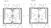
- FIG illustrations 4 A and 4 B each show an electrolytic cell E ⁇ 1> according to the second aspect of the invention. These each correspond to FIG illustration 1 A shown electrolytic cell with the difference that a partition wall W ⁇ 16> separates the interior I KK ⁇ 122> of the cathode chamber K K ⁇ 12> from the interior I KA ⁇ 112> of the anode chamber K A ⁇ 11>.
- the partition is that shown in Figures 2A or 2B.
- FIG. 4A a screw used as fasteners B R ⁇ 91> and B T ⁇ 92>.
- the cross section Q RR ⁇ 165> in the area of the edge element R R ⁇ 20> of the partition W ⁇ 16> and the cross section Q RT ⁇ 166> in the area of the partition element R T ⁇ 17> of the partition W ⁇ 16> is as in FIG Figure 3A described.
- interlocking hooks are used as fasteners B R ⁇ 91> and B T ⁇ 92>.
- the cross section Q RR ⁇ 165> in the area of the edge element R R ⁇ 20> of the partition W ⁇ 16> and the cross section Q RT ⁇ 166> in the area of the partition element R T ⁇ 17> of the partition W ⁇ 16> is as in FIG Figure 3B described.
- Figure 5A shows an electrolytic cell E ⁇ 1> according to the second aspect of the invention. This corresponds to that in Figure 1B shown electrolytic cell with the difference that a partition W ⁇ 16> separates the interior I KK ⁇ 122> of the cathode chamber K K ⁇ 12> from the interior I KM ⁇ 132> of the central chamber K M ⁇ 13>.
- the partition W ⁇ 16> is that shown in Figures 2A or 2B.
- a screw used as fasteners B R ⁇ 91> and B T ⁇ 92> are screw used as fasteners B R ⁇ 91> and B T ⁇ 92>.
- the cross section Q RR ⁇ 165> in the area of the edge element R R ⁇ 20> of the partition W ⁇ 16> and the cross section Q RT ⁇ 166> in the area of the partition element R T ⁇ 17> of the partition W ⁇ 16> is as in FIG Figure 3A described.
- the separating element R T ⁇ 17> is the portion of the frame element R ⁇ 2> shown hatched in Figures 6A and 6B.
- Figure 6A shows another embodiment of a partition wall W ⁇ 16> according to the invention in a top view of side S KK ⁇ 161> with surface O KK ⁇ 163> (left) and then as a side view of the section that extends through the curved bracket in the direction of view of the arrow results.
- the frame element R ⁇ 2> forms an edge element R R ⁇ 20> and a separating element R T ⁇ 17>.
- the separating element R T ⁇ 17> is cross-shaped and lies between the NaSICON solid electrolyte ceramics FA ⁇ 18>, FB ⁇ 19>, FC ⁇ 28> and FD ⁇ 29> and separates them from one another.
- the separating element R T ⁇ 17> is the portion of the frame element R ⁇ 2> shown hatched in Figures 6A and 6B.
- the edge element R R ⁇ 20> is the part of the frame element R ⁇ 2> that is not shown hatched in Figures 6 A and 6 B.
- the two frame parts R 1 ⁇ 201> and R 2 ⁇ 202> are fastened to one another in the area of the edge element R R ⁇ 20> by a fastening element B R ⁇ 91>, and in the area of the separating element R T ⁇ 17> by a fastening element B T ⁇ 92> attached to each other. They can optionally be connected to each other via a hinge ⁇ 50>.
- a rubber ring is preferably used as a seal Di ⁇ 40> attached.
- the rings acting as a seal Di ⁇ 40> are shown in the front view on the left side of Figure 6A indicated with dashed outlines.
- Figure 6B shows a further embodiment of a partition wall W ⁇ 16> according to the invention. This corresponds to that in Figure 6A described embodiment, except that they nine NaSICON solid electrolyte ceramics FA ⁇ 18>, FB ⁇ 19>, FC ⁇ 28>, FD ⁇ 29>, FE ⁇ 30>, FF ⁇ 31>, FG ⁇ 32>, FH ⁇ 33>, FI ⁇ 34>.
- the frame element R ⁇ 2> additionally has four bulges ⁇ 60>, each with a hole ⁇ 61>("rabbitears"), with which the dividing wall can be fastened, for example, to a cathode chamber K K ⁇ 12> with corresponding configurations.
- the present invention relates to a partition wall W.
- This is particularly suitable as a partition wall in an electrolytic cell, in particular an electrolytic cell E.
- the present invention thus also relates to an electrolytic cell comprising the partition wall W, in particular an electrolytic cell E comprising the partition wall W.
- the dividing wall W comprises at least two alkali cation-conducting solid electrolyte ceramics ("alkali cation-conducting solid electrolyte ceramics" is abbreviated to "AFK” below) F A and F B , separated from one another by a separating element R T .
- alkali cation-conducting solid electrolyte ceramics is abbreviated to "AFK” below
- the partition wall W comprises two sides S KK and S A/MK that face each other, that is, the side S A/MK faces the side S KK (and vice versa).
- the two sides S KK and S A/MK comprise planes which are essentially parallel to one another.
- the geometry of the partition wall W is otherwise not further restricted and can in particular be adapted to the cross section of the electrolytic cell E in which it is used.
- it may have the geometry of a parallelepiped and thus have a rectangular cross-section, or the geometry of a truncated cone or cylinder and thus have a circular cross-section.
- the partition W can also have the geometry of a cuboid with rounded corners and/or bulges, which in turn can have holes.
- the dividing wall W then has bulges ("rabbit ears") with which the dividing wall W can be fixed to electrolytic cells or the two frame parts R 1 and R 2 of the dividing wall W can be fixed to one another.
- the side S KK of the partition W has the surface O KK and the side S A / MK of the partition W has the surface O A / MK .
- the partition wall W comprises a frame element R. This comprises two opposing parts, preferably halves, R 1 and R 2 , between which at least two alkali cation-conducting solid electrolyte ceramics F A and F B are arranged. R 1 can be contacted directly via the surface O KK , R 2 can be contacted directly via the surface O A/MK .
- the frame element R forms an edge element R R and a separating element R T , with the edge element R R delimiting and preferably completely enclosing the surfaces O KK and O A/MK , and the separating element R T between the solid electrolyte ceramics which are conductive to alkali cations and are enclosed by the partition W lies and separates them from each other, so that the alkali cation-conducting solid electrolyte ceramics enclosed by the partition W can be contacted directly via the surface O KK as well as via the surface O A/MK ,
- partition wall means that the partition wall W is liquid-tight. This means that the AFKs and the frame element R connect to one another without a gap. There are thus no gaps between the frame element R and the AFKs enclosed by the partition W , through which aqueous solution, alcoholic solution, alcohol or water could flow from side S KK to side S A/MK or vice versa.
- S KK and S A / MK im Refers to the meaning of the invention, which includes the largest surfaces O KK and O A / MK . If the surfaces encompassed by two pairs of opposite sides are of the same size, one skilled in the art can select a pair as S KK and S A/MK with surfaces O KK and O A/MK , respectively.
- partitions W in which there are two or more pairs of opposite sides, via whose surfaces the alkali cation-conducting solid electrolyte ceramics comprised by the partition W and the respective part R 1 or R 2 can be contacted directly, the partitions W are preferred in which the respective pair of opposite sides comprised surfaces are of different sizes, in which case the pair of opposite sides is referred to as S KK and S A / MK for the purposes of the invention, which comprises the largest surfaces O KK and O A / MK .
- the bulkhead W according to the first aspect of the present invention also includes embodiments in which the bulkhead W includes more than two AFKs, eg four or nine or twelve AFKs.
- all of the AFKs comprised by the partition W are separated from one another by the separating element R T of the frame element R , which means that no AFK directly borders another AFK, i.e. without a frame element R being in between.
- the partition wall W is further characterized in that the AFKs encompassed by the partition wall W can be contacted directly both via the surface O KK and via the surface O A/MK .
- Directly contactable means, with reference to the AFKs encompassed by the partition W , that part of the surfaces O KK and O A/MK are encompassed by the surface of the partition W AFKs is formed, which means that the AFKs enclosed by the partition W are directly accessible on the two surfaces O KK and O A/MK , so that they can be treated on the two surfaces O KK and O A/MK , for example with an aqueous solution, alcoholic solution, alcohol or water can be wetted.
- the two frame parts R 1 and R 2 can be contacted directly via the surfaces O KK or O A/MK .
- Directly contactable means, with regard to the frame part R 1 enclosed by the partition W , that part of the surface O KK is formed by the surface of the frame part R 1 , i.e. the frame part R 1 is directly accessible at the surface O KK is, so that it can be wetted on the surface O KK , for example, with an aqueous solution, alcoholic solution, alcohol or water.
- Directly contactable means, with reference to the frame part R 2 surrounded by the partition W , that part of the surface O A/MK is formed by the surface of the frame part R 2 , that is to say that the frame part R 2 is attached to the surface O A/ MK is directly accessible, so that it can be wetted on the surface O A / MK , for example with an aqueous solution, alcoholic solution, alcohol or water.
- the partition W In a preferred embodiment of the partition W according to the first aspect of the invention, 50% to 95%, more preferably 60 to 90%, more preferably 70 to 85% of the surface area O KK are formed by the AFKs comprised by the partition W , with the Rest of the surface O KK are formed by the frame part R 1 .
- the partition W In a preferred embodiment of the partition W according to the first aspect of the invention, 50% to 95%, more preferably 60 to 90%, even more preferably 70 to 85% of the surface area O A/MK are formed by the AFKs comprised by the partition W , where even more preferably the remainder of the surface O A/MK are formed by the frame part R 2 .
- the partition wall W in particular between the frame element R and the AFKs, comprises a seal Di (e.g. in Figures 3A, 3B and 3C shown). This ensures particularly well that the partition wall W is liquid-tight.
- the seal Di can be selected by a person skilled in the art for the respective AFK or the respective frame element R.
- the seal Di comprises a material selected from the group consisting of elastomers, adhesives, preferably elastomers.
- a particularly suitable elastomer is rubber, preferably ethylene-propylene-diene rubber (“EPDM”), fluoropolymer rubber (“FPM”), perfluoropolymer rubber (“FFPM”), acrylonitrile butadiene rubber (“NBR”).
- EPDM ethylene-propylene-diene rubber
- FPM fluoropolymer rubber
- FFPM perfluoropolymer rubber
- NBR acrylonitrile butadiene rubber
- the seal Di is preferably selected such that it is compressed between the two frame parts R 1 and R 2 when the two frame parts R 1 and R 2 are fastened to one another and the AFKs are arranged. This further increases the tightness of the partition wall W.
- the partition W comprises at least four AFKs FA, FB , FC and FD , in which case it more preferably comprises precisely four AFKs FA , FB , FC and FD .
- the partition W comprises at least nine AFKs FA, FB , FC, FD, FE, FF , FG , FH and FI , in which case it is even more preferred to have exactly nine AFKs FA , F B , F C , F D , F E , F F , F G , F H and F I .
- the partition wall W comprises at least twelve AFKs FA , FB , FC, FD , FE , FF, FG , FH, FI , FJ , FK and FL , with then more preferably exactly twelve AFKs F A , F B , F C , F D , F E , F F , F G , F H , F I , F J , F K and F L .
- This arrangement according to the invention of at least two AFKs next to one another in the partition wall W results in a further direction of propagation for the AFKs in the temperature fluctuations that arise during operation of the electrolytic cell compared to the conventional partition walls in the electrolytic cells of the prior art.
- the NaSICON discs which act as partitions, are bounded by the outer walls of the electrolytic cell or by solid plastic frames. The mechanical stresses that occur within the NaSICON during expansion cannot be dissipated, which can lead to the ceramic breaking.
- the frame element R comprises two opposing parts R 1 and R 2 , between which the at least two alkali cation-conducting solid electrolyte ceramics F A and F B comprised by the partition W are arranged.
- This arrangement can take place in any manner familiar to a person skilled in the art.
- the two parts R 1 and R 2 clamp the AFKs between them, with a seal Di preferably being used, which gives the AFKs in the frame element R additional support.
- the AFKs are glued to the two frame parts R 1 and R 2 . All adhesives familiar to the person skilled in the art that are stable under the conditions of the electrolysis can be used as adhesives KI .
- Preferred KI include at least one substance selected from epoxy resins, phenolic resins.
- the partition wall W can have a hinge on which the two parts R 1 and R 2 of the frame element R can be opened and closed.
- the frame element R comprises a material that is selected from the group consisting of plastic, glass, and wood.
- the frame element R particularly preferably comprises plastic. More preferably, the plastic is one selected from the group consisting of polypropylene, polystyrene, polyvinyl chloride.
- a seal Di is fitted between the frame element R and the AFKs comprised by the partition wall W. This improves the liquid tightness of the partition wall W.
- the frame element R forms an edge element R R and a separating element R T .
- the area of the frame element R that lies between at least two AFKs and separates them from one another is referred to as the separating element R T .
- the separating element R T as a region of the frame element R is formed by the two parts R 1 and R 2 .
- any body through which the respective AFKs can be arranged separately from one another is suitable as the separating element R T , which is formed by the frame element R.
- the AFCs connect seamlessly to the separating element R T , in order not to impair the function of the dividing wall W , which is intended to separate the cathode chamber in the electrolytic cell E from the adjacent central or anode chamber in a liquid-tight manner.
- the shape of the separating element R T can be selected by a person skilled in the art, in particular depending on the number and shape of the AFCs which the dividing wall W comprises.
- the partition wall W comprises two or three AFKs, for example, these can each be separated by a web arranged between the AFKs as a separating element R T (see e.g Figure 2A) .
- partition wall W comprises four or more AFKs
- these can be separated by a separating element R T which has the shape of a cross (see Figure 2B and 6 A ) or grid (see Figure 6B) has to be separated.
- the dividing wall W comprises at least four AFKs and even more preferred that the separating element R T is then cruciform or grid-shaped, since the AFKs then have all three dimensions fully available for thermal expansion/shrinkage.
- the separating element R T is in particular formed in such a way that the respective AFK can be fitted or clamped into the separating element. This can already be carried out accordingly during the production of the partition wall W.
- the separating element R T preferably comprises a material selected from the group consisting of plastic, glass and wood.
- the separating element R T particularly preferably comprises plastic.
- the plastic is one selected from the group consisting of polypropylene, polystyrene, polyvinyl chloride (“PVC”).
- PVC also includes post-chlorinated polyvinyl chloride (“PVC-C”).
- the frame element R In addition to the separating element R T , the frame element R also forms an edge element R R .
- the edge element R R as a region of the frame element R is formed by the two parts R 1 and R 2 .
- the edge element R R (in contrast to the separating element R T ) is that area of the frame element R which is not arranged between the alkali cation-conducting solid electrolyte ceramics comprised by the dividing wall W , ie does not separate them from one another.
- the edge element R R delimits the surfaces O KK and O A/MK at least partially, preferably completely. This means in particular: The boundary element R R encloses the surfaces O KK and O A/MK at least partially, preferably completely.
- the edge element R R may or may not be formed as part of the surfaces O KK and O A/MK .
- the edge element R R is preferably formed as part of the surfaces O KK and O A/MK .
- the edge element R R can be contacted directly or cannot be contacted directly, in particular via the surfaces O KK and O A/MK .
- edge element R R completely forms the surfaces of those sides of the partition W that are not the sides S KK and S A /MK .
- the edge element R R preferably comprises a material which is selected from the group consisting of plastic, glass and wood.
- the edge element R R particularly preferably comprises plastic. More preferably, the plastic is one selected from the group consisting of polypropylene, polystyrene, polyvinyl chloride (“PVC”). PVC also includes post-chlorinated polyvinyl chloride (“PVC-C").
- edge element R R and the separating element R T comprise the same material, more preferably both comprise plastic, which is even more preferably selected from polypropylene, polystyrene, polyvinyl chloride, PVC-C.
- At least a portion of the divider R T is integral with at least a portion of the frame member R R . This means in particular that at least part of the separating element R T merges into the edge element R R .
- an edge element R R has the further advantage that it functions in the electrolytic cell E as part of the outer wall.
- This part of the partition wall W does not contact the solutions in the respective inner space I KK , I KA and I KM , which is why it would be wasteful to form this part of the partition wall W with a solid electrolyte ceramic.
- the part of the partition wall W which is clamped between or forms part of the outer wall is subjected to forces which the brittle solid electrolyte ceramic may not withstand. Instead, a shatterproof and cheaper material is selected for the frame element R.
- the partition wall W according to the first aspect of the invention is characterized in that R 1 and R 2 are fastened to one another by at least one fastening element B R on the edge element R R , and R 1 and R 2 are secured together by at least one fastener B T on the divider R T .
- fastening elements B R and B T Any means familiar to a person skilled in the art for fastening the two frame parts R 1 and R 2 to one another are suitable as fastening elements B R and B T .
- fastening elements B R and B T are selected in particular from hinges, clips, nails, screws, hooks, preferably from screws, hooks, most preferably hooks.
- the fasteners B R and B T can be made of any material familiar to those skilled in the art. They preferably include a material selected from the group consisting of plastic, glass, and wood. Plastic is particularly preferred. More preferably, the plastic is one selected from the group consisting of polypropylene, polystyrene, polyvinyl chloride, PVC-C.
- the at least one fastener B R and the at least one fastener B T are each in the form of interlocking hooks B H . When fastened to one another, these hooks span the partition wall W in particular.
- opposing pairs of hooks B H are advantageously formed as B T on the mutually facing sides of the two frame parts R 1 and R 2 in the area of the separating element R T , which are preferred when the AFKs are arranged between the frame parts R 1 and R 2 reversible, intertwine.
- the edge element R R must be able to be contacted directly via the surfaces O KK and O A/MK .
- opposing pairs of hooks B H are advantageously formed as B R on the mutually facing sides of the two frame parts R 1 and R 2 in the area of the edge element R R , which reversibly interlock when the AFK is arranged between the frame parts R 1 and R 2 grasp.
- “Facing sides of the two frame parts R 1 and R 2 ” refers to the sides of the two frame parts whose surface is not directly contactable via the surface O KK in the case of R 1 and whose surface is not directly contactable via the surface in the case of R 2 O A/MK can be contacted directly. In particular, these are the surfaces of R 1 and R 2 that contact the AFKs and/or the seal Di in the partition wall W.
- the fastening means B R and B T are preferably designed in one piece with at least one of the parts R 1 and R 2 ( Figure 3B) .
- the at least one fastening element B R and the at least one fastening element B T are each in the form of interlocking hooks B H .
- hooks B H are formed on both frame parts R 1 and R 2 in the area of the separating element R T and in the area of the edge element R R such that they engage in one another when the AFKs are arranged between the frame parts R 1 and R 2 and so fasten the frame parts R 1 and R 2 together.
- this is reversible, i.e. the hooks BH can be detached from one another. This can be achieved, for example, by designing the hooks to be displaceable relative to one another.
- any solid electrolyte through which cations, in particular alkali cations, more preferably sodium cations, can be transported from side S A/MK to side S KK can be considered as the solid electrolyte ceramics F A , F B etc. which conduct alkali cations and are enclosed by partition W.
- Such solid electrolytes are known to those skilled in the art and, for example, in DE 10 2015 013 155 A1 , in the WO 2012/048032 A2 , paragraphs [0035], [0039], [0040], in the US 2010/0044242 A1 , paragraphs [0040], [0041], in which DE 10360758 A1 , paragraphs [014] to [025].
- NaSICON LiSICON
- KSICON KSICON
- a sodium ion conductive solid electrolyte is preferred, more preferably having a NaSICON structure.
- NaSICON structures that can be used according to the invention are also described by way of example Anantharamulu N, Koteswara Rao K, Rambabu G, Vijaya Kumar B, Radha Velchuri, Vithal M, J Mater Sci 2011, 46, 2821-2837 .
- w, x, y, z are real numbers, where 0 ⁇ x ⁇ 2, 0 ⁇ y ⁇ 2, 0 ⁇ w ⁇ 2, 0 ⁇ z ⁇ 3, and where w, x, y, z are so chosen become that 1 + 2w + x - y + z ⁇ 0 and 2 - w - x - y ⁇ 0.
- the AFKs comprised by the partition wall W have the same structure.
- the partition wall W can be produced by methods known to those skilled in the art.
- the AFKs enclosed by the partition W can be placed in a corresponding mold and the frame element R can be cast over liquid plastic and then allowed to solidify (injection molding process). When it freezes, it then encloses the AFKs.
- the fastening elements B T and B R can be attached to the frame element R in one piece by a suitable mold (and are then present in one piece with it).
- interlocking hooks B H are particularly suitable as fastening means.
- the frame element R or the frame parts R 1 and R 2 is cast separately.
- the fastening elements B T and B R can be attached to the frame element R in one piece by a suitable mold (and are then present in one piece with it).
- interlocking hooks B H are particularly suitable as fastening means.
- the AFKs optionally with the seal Di, can be arranged between the frame parts R 1 and R 2 and the fastening elements B T and B R can then be attached. Screws or nails are suitable for this purpose, for example, which are driven through suitable openings in the frame parts R 1 and R 2 and attach them to one another. and then attached (e.g. glued) to the at least two AFKs without any gaps.
- the electrolytic cell E comprises at least one anode chamber K A and at least one cathode chamber K K and optionally at least one intermediate chamber K M .
- This also includes electrolytic cells E which have more than one anode chamber K A and/or cathode chamber K K and/or middle chamber K M .
- Such electrolytic cells, in which these chambers are joined together in a modular manner, are, for example, in DD 258 143 A3 and the U.S. 2006/0226022 A1 described.
- the electrolytic cell E according to the second aspect of the invention comprises an anode chamber K A and a cathode chamber K K and optionally a middle chamber K M lying in between.
- the electrolytic cell E usually has an outer wall W A .
- the outer wall W A is in particular made of a material selected from the group consisting of steel, preferably rubberized steel, plastic, in particular Telene® (thermosetting polydicyclopentadiene), PVC (polyvinyl chloride), PVC-C (post-chlorinated polyvinyl chloride), PVDF (polyvinylidene fluoride) is selected.
- W A can be perforated in particular for inlets and outlets.
- Within W A then lie the at least one anode chamber K A , the at least one cathode chamber K K and, in the embodiments in which the electrolytic cell E comprises such, the at least one intermediate chamber K M .
- the cathode chamber K K has at least one inlet Z KK , at least one outlet A KK and an interior space I KK , which includes a cathodic electrode E K .
- the interior space I KK of the cathode chamber K K is separated from the interior space I KA of the anode chamber K A by the partition W according to the first aspect of the invention if the electrolytic cell E does not include a middle chamber K M .
- the interior I KK of the cathode chamber K K is separated from the interior I KM of the middle chamber K M by the partition W according to the first aspect of the invention if the electrolytic cell E comprises at least one middle chamber K M .
- the cathode chamber K K includes an interior space I KK , which in turn includes a cathodic electrode E K .
- a cathodic electrode E K Any electrode familiar to a person skilled in the art that is stable under the conditions of the method according to the third aspect of the invention can be used as such a cathodic electrode E K .
- This electrode E K can be selected from the group consisting of mesh wool, three-dimensional matrix structure or "balls”.
- the cathodic electrode E K comprises in particular a material which is selected from the group consisting of steel, nickel, copper, platinum, platinized metals, palladium, palladium supported on carbon, titanium. E K preferably comprises nickel.
- the electrolytic cell E in which it comprises a central chamber K M , this is located between the anode chamber K A and the cathode chamber K K .
- the cathode chamber K K also includes an inlet Z KK and an outlet A KK .
- the inlet Z KK and the outlet A KK are attached to the cathode chamber K K in such a way that the liquid makes contact with the cathodic electrode E K as it flows through the interior I KK of the cathode chamber K K .
- the solution L 1 is obtained at the end A KK when the solution L 2 of an alkali metal alkoxide XOR in the alcohol ROH is passed through the interior I KK of the cathode chamber K K .
- the inlet Z KK and the outlet A KK can be attached to the electrolytic cell E by methods known to those skilled in the art, for example through bores in the outer wall and appropriate connections (valves) that simplify the introduction and removal of liquid.
- the anode chamber K A has at least one inlet Z KA , at least one outlet A KA and an interior space I KA , which includes an anodic electrode E A .
- the interior space I KA of the anode chamber K A is separated from the interior space I KM of the center chamber K M by a diffusion barrier D if the electrolytic cell E includes a central chamber K M .
- the electrolytic cell E does not include a middle chamber K M , the interior space I KA of the anode chamber K is separated by the partition wall W from the interior space I KK of the cathode chamber K K .
- the anode chamber K A includes an interior space I KA , which in turn includes an anodic electrode E A .
- Any electrode familiar to a person skilled in the art that is stable under the conditions of the method according to the third aspect of the invention can be used as such an anodic electrode E A .
- Such are in particular in WO 2014/008410 A1 , paragraph [024] or DE 10360758 A1 , paragraph [031].
- This electrode E A can consist of one layer or of several planar, mutually parallel layers, each of which can be perforated or expanded.
- the anodic electrode E A comprises in particular a material which is selected from the group consisting of ruthenium oxide, iridium oxide, nickel, cobalt, nickel tungstate, nickel titanate, noble metals such as platinum in particular, which is deposited on a carrier such as titanium or Kovar® (an iron/nickel/ Cobalt alloy, in which the individual proportions are preferably as follows: 54% by mass iron, 29% by mass nickel, 17% by mass cobalt) is supported.
- Other possible anode materials are, in particular, stainless steel, lead, graphite, tungsten carbide, titanium diboride.
- the anodic electrode E A preferably comprises a titanium anode (RuO 2 +IrO 2 /Ti) coated with ruthenium oxide/iridium oxide.
- the anode chamber K A also includes an inlet Z KA and an outlet A KA .
- the inlet Z KA and the outlet A KA are attached to the anode chamber K A in such a way that the liquid makes contact with the anodic electrode E A as it flows through the interior space I KA of the anode chamber K A .
- This is the prerequisite for the solution L 4 being obtained at the outlet A KA when the process according to the third aspect of the invention is carried out if the solution L 3 of a salt S is passed through the interior space I KA of the anode chamber KA .
- the inlet Z KA and the outlet A KA can be attached to the electrolytic cell E by methods known to those skilled in the art, eg through bores in the outer wall and corresponding connections (valves) which simplify the introduction and removal of liquid.
- the electrolytic cell E comprises a central chamber K M
- the inlet Z KA can also lie within the electrolytic cell, for example as a perforation in the diffusion barrier D.
- the electrolytic cell E according to the second aspect of the invention preferably has a central chamber K M .
- the optional middle chamber K M is located between the cathode chamber K K and the anode chamber K A . It comprises at least one inlet Z KM , at least one outlet A KM and an interior I KM .
- the interior space I KA of the anode chamber K A is separated from the interior space I KM of the center chamber K M by a diffusion barrier D if the electrolytic cell E includes a central chamber K M .
- a KM is then also connected to the inlet Z KA by a connection V AM , so that liquid can be conducted from I KM into I KA through the connection V AM .
- the interior I KM of the optional central chamber K M is separated from the interior I KA of the anode chamber K A by a diffusion barrier D and is separated from the interior I KK of the cathode chamber K K by the partition W.
- Any material which is stable under the conditions of the method according to the third aspect of the invention and which prevents the transfer of protons from the liquid located in the interior I KA of the anode chamber K A to the interior I KM of the optional middle chamber K can be used for the diffusion barrier D M prevented or slowed down.
- a non-ion-specific dividing wall or a membrane permeable to specific ions is used as the diffusion barrier D.
- the diffusion barrier D is preferably a non-ion-specific partition.
- the material of the non-ion-specific partition wall is in particular selected from the group consisting of fabric, in particular textile fabric or metal fabric, glass, in particular sintered glass or glass frits, ceramic, in particular ceramic frits, membrane diaphragms, and is selected particularly preferably a textile fabric or metal fabric, particularly preferably a textile fabric.
- the textile fabric preferably comprises plastic, more preferably a plastic selected from PVC, PVC-C, polyvinyl ether (“PVE”), polytetrafluoroethylene (“PTFE”). If the diffusion barrier D is a “membrane that is permeable to specific ions”, this means according to the invention that the respective membrane favors the diffusion of certain ions through it compared to other ions.
- the diffusion barrier D is a “membrane permeable to specific ions”, the diffusion barrier D is in particular an anion-conducting membrane or a cation-conducting membrane.
- anion-conducting membranes are those which selectively conduct anions, preferably selectively specific anions. In other words, they favor the diffusion of anions through them over that of cations, especially over protons, more preferably they additionally favor the diffusion of certain anions through them over the diffusion of other anions through them.
- cation-conducting membranes are those which selectively conduct cations, preferably selectively specific cations. In other words, they favor the diffusion of cations through them over that of anions, more preferably they additionally favor the diffusion of certain cations through them over the diffusion of other cations through them, much more preferably cations where there is are not protons, more preferably sodium cations, over protons.
- “Favour the diffusion of certain ions X compared to the diffusion of other ions Y” means in particular that the diffusion coefficient (unit m 2 /s) of the ion species X at a given temperature for the membrane in question is higher by a factor of 10, preferably 100, preferably 1000 as the diffusion coefficient of the ionic species Y for the membrane in question.
- the diffusion barrier D is a “membrane that is permeable to specific ions”, it is preferably an anion-conducting membrane because this prevents the diffusion of protons from the anode chamber K A into the middle chamber K M particularly well.
- a membrane which is selective for the anions comprised by the salt S is used as the anion-conducting membrane.
- Such membranes are known to those skilled in the art and can be used by them.
- the salt S is preferably a halide, sulfate, sulfite, nitrate, bicarbonate or carbonate of X, more preferably a halide.
- Halides are fluorides, chlorides, bromides, iodides. The most preferred halide is chloride.
- a membrane selective for halides preferably chloride, is preferably used as the anion-conducting membrane.
- Anion-conducting membranes are for example by MA Hickner, AM Herring, EB Coughlin, Journal of Polymer Science, Part B: Polymer Physics 2013, 51, 1727-1735 , by CG Arges, V Ramani, PN Pintauro, Electrochemical Society Interface 2010, 19, 31-35 , in WO 2007/048712 A2 as well as on page 181 of the textbook by Volkmar M. Schmidt Electrochemical Process Engineering: Basics, Reaction Engineering, Process Optimization, 1st edition (October 8, 2003 ) described.
- they have covalently bonded functional groups selected from -NH 3 + , -NRH 2 + , -NR 3 + , more preferably selected from -NH 3 + , -NR 3 + , even more preferably -NR 3 + .
- the diffusion barrier D is a cation-conducting membrane, it is in particular a membrane that is selective for the cations comprised by the salt S.
- the diffusion barrier D is even more preferably an alkali cation-conducting membrane, even more preferably a potassium and/or sodium ion-conducting membrane, most preferably a sodium ion-conducting membrane.
- Cation-conducting membranes are described, for example, in Page 181 of the textbook by Volkmar M. Schmidt Electrochemical Process Engineering: Fundamentals, Reaction Engineering, Process Optimization, 1st edition (October 8, 2003 ).
- organic polymers which are selected in particular from polyethylene, polybenzimidazoles, polyetherketones, polystyrene, polypropylene or fluorinated membranes such as polyperfluoroethylene, preferably polystyrene, polyperfluoroethylene, are even more preferably used as the cation-conducting membrane, with these covalently bonded functional groups selected from -SO 3 - , -COO - , -PO 3 2- , -PO 2 H - , preferably -SO 3 - , (described in DE 10 2010 062 804 A1 , U.S. 4,831,146 ) carry.
- Neosepta® membranes are described, for example by SA Mareev, D.Yu. Butylskii, ND Pismenskaya, C Larchet, L Dammak, VV Nikonenko, Journal of Membrane Science 2018, 563, 768-776 .
- a cation-conducting membrane is used as the diffusion barrier D , this can be, for example, a polymer functionalized with sulfonic acid groups, in particular of the following formula P NAFION , where n and m independently of one another are an integer from 1 to 10 6 , more preferably an integer from 10 to 10 5 , more preferably is an integer from 10 2 to 10 4 .
- the optional middle chamber K M also includes an inlet Z KM and an outlet A KM . This makes it possible to add liquid, such as solution L 3 , to the interior space I KM of the middle chamber K M , and to transfer liquid therein, such as solution L 3 , to the anode chamber K A .
- the inlet Z KM and the outlet A KM can be attached to the electrolytic cell E by methods known to those skilled in the art, for example through bores in the outer wall and corresponding connections (valves) that simplify the introduction and removal of liquid.
- the drain A KM can also be within the electrolytic cell, for example as a perforation in the diffusion barrier D.
- the outlet A KM is connected to the inlet Z KA by a connection V AM in such a way that liquid can be passed from I KM into I KA through the connection V AM
- Outflow A KM at the bottom of the middle chamber K M means that the outflow A KM is attached to the electrolytic cell E in such a way that the solution L 3 leaves the middle chamber K M in the same direction as gravity.
- Inlet Z KA at the bottom of the anode chamber K A means that the inlet Z KA is attached to the electrolytic cell E in such a way that the solution L 3 enters the anode chamber K A against the force of gravity.
- Inlet Z KM at the top of the middle chamber K M means that the inlet Z KM is attached to the electrolytic cell E in such a way that the solution L 3 enters the middle chamber K M in the same direction as gravity.
- Outlet A KA at the top of the anode chamber K A means that the outlet A KA is attached to the electrolytic cell E in such a way that the solution L 4 leaves the anode chamber K A against the force of gravity.
- outlet A KM is formed by the outer wall WA at the bottom of the central chamber K M and the inlet Z KA is formed by the outer wall WA at the bottom of the anode chamber KA.
- This arrangement makes it particularly easy to discharge gases formed in the anode chamber K A with L 4 from the anode chamber K A in order to then separate them further.
- connection V AM is formed outside the electrolytic cell E, in particular Z KM and A KM are arranged on opposite sides of the outer wall W A of the central chamber K M (i.e. Z KM on the bottom and A KM on the top of the electrolytic cell E or vice versa) and Z KA and A KA are arranged on opposite sides of the outer wall W A of the anode chamber K A (i.e. Z KA on the bottom and A KA on the top of the electrolytic cell E or vice versa), as is particularly the case in Figure 5A is shown. Due to this geometry, L 3 must flow through the two chambers K M and K A .
- Z KA and Z KM can be formed on the same side of the electrolytic cell E , with A KM and A KA then automatically also being formed on the same side of the electrolytic cell E.
- Z KA and Z KM can be formed on opposite sides of the electrolytic cell E , with A KM and A KA then automatically also being formed on opposite sides of the electrolytic cell E.
- connection V AM is formed inside the electrolytic cell E , this can be ensured in particular by giving preference to one side ("side A") of the electrolytic cell E, which is the top or the bottom of the electrolytic cell E as in Figure 6B shown is the top, includes the inlet Z KM and the outlet A KA and the diffusion barrier D extends from this side ("side A") into the electrolytic cell E , but not quite to the side opposite side A ("side A").
- Bottom of the electrolytic cell E is, according to the invention, the side of the electrolytic cell E through which a solution (e.g. L 3 at A KM in Figure 5A) rectified with gravity from the electrolytic cell E exits or the side of the electrolytic cell E, through which a solution (e.g. L 2 at Z KK in Figures 5 A and 5 B and L 3 at A KA in Figures 4 A and 4 B) of Electrolytic cell E is fed against gravity.
- a solution e.g. L 3 at A KM in Figure 5A
- a solution e.g. L 2 at Z KK in Figures 5 A and 5 B and L 3 at A KA in Figures 4 A and 4 B
- top side of the electrolytic cell E is the side of the electrolytic cell E through which a solution (e.g.
- the dividing wall W is arranged in the electrolytic cell E in such a way that the solid electrolyte ceramics, which conduct alkali cations and are contained by the dividing wall W , and preferably also the frame element R, directly contact the interior space I KK on the side S KK via the surface O KK .
- the partition wall W is arranged in the electrolytic cell E in such a way that when the interior space I KK is completely filled with solution L 4 on the side S KK , the solution L 4 then covers all of the surface O KK from the Partition W comprised alkali cation-conducting solid electrolyte ceramics and preferably also contacted the frame element R via the part R 1 , so that ions (e.g. alkali metal ions such as sodium, lithium) from all AFKs that were covered by the partition W can enter the solution L 4 .
- ions e.g. alkali metal ions such as sodium, lithium
- the partition W is arranged in the electrolytic cell E in such a way that the solid electrolyte ceramics which conduct alkali cations and are contained in the partition W , and preferably also the frame element R, have the interior space I KA on the Page S Contact A/MK directly via the O A/MK interface.
- the partition wall W borders on the interior space I KA of the anode chamber K A .
- the partition wall W is arranged in the electrolytic cell E in such a way that when the interior space I KA on the side S A/MK is completely filled with solution L 2 , the solution L 2 then covers the surface O A/MK all of the solid electrolyte ceramics which conduct alkali cations and which are included in the partition W and preferably also contact the frame element R via the part R 2 , so that ions (e.g. alkali metal ions such as sodium, lithium) from the solution L 2 enter each AFC that is included in the partition W can.
- ions e.g. alkali metal ions such as sodium, lithium
- the dividing wall W is arranged in the electrolytic cell E in such a way that the solid electrolyte ceramics, which conduct alkali cations, are comprised by the dividing wall W , and preferably also the frame element R, the interior space I KM Contact the S A/MK side directly via the O A/MK interface.
- the partition wall W borders on the interior space I KM of the central chamber K M .
- the dividing wall W is arranged in the electrolytic cell E in such a way that when the interior space I KM on the side S A/MK is completely filled with solution L 2 , the solution L 2 then all over the surface O A/MK of the solid electrolyte ceramics which conduct alkali cations and which are included in the partition W and preferably also contact the frame element R via the part R 2 , so that ions (e.g. alkali metal ions such as sodium, lithium) from the solution L 2 enter each AFC that is included in the partition W can.
- ions e.g. alkali metal ions such as sodium, lithium
- the present invention relates to a process for preparing a solution L 1 of an alkali metal alkoxide XOR in the alcohol ROH, where X is an alkali metal cation and R is an alkyl radical having 1 to 4 carbon atoms.
- the method according to the third aspect of the invention is carried out in an electrolytic cell E according to the second aspect of the invention.
- R is preferably selected from the group consisting of n -propyl, iso -propyl, ethyl, methyl, more preferably selected from the group consisting of ethyl, methyl. Most preferably R is methyl.
- the steps ( ⁇ 1), ( ⁇ 2), ( ⁇ 3) running simultaneously are carried out.
- step ( ⁇ 1) a solution L 2 comprising the alcohol ROH, preferably comprising an alkali metal alkoxide XOR and alcohol ROH, is passed through K K .
- the solution L 2 is preferably free of water.
- “free of water” means that the weight of the water in the solution L 2 based on the weight of the alcohol ROH in the solution L 2 (mass ratio) is ⁇ 1:10, more preferably ⁇ 1:20, even more preferably ⁇ 1:100 , more preferably ⁇ 0.5:100.
- the mass fraction of XOR in the solution L 2 is in particular >0 to 30% by weight, preferably 5 to 20% by weight, even more preferably at 10 to 20% by weight, more preferably at 10 to 15% by weight, most preferably at 13 to 14% by weight, most preferably at 13% by weight.
- the mass ratio of XOR to alcohol ROH in the solution L 2 is in particular in the range from 1:100 to 1:5, more preferably in the range from 1:25 to 3:20, even more preferably in the range 1:12 to 1:8, more preferably at 1:10.
- step ( ⁇ 2) a neutral or alkaline, aqueous solution L 3 of a salt S comprising X as a cation is passed through K A .
- the salt S is preferably a halide, sulfate, sulfite, nitrate, bicarbonate or carbonate of X, more preferably a halide.
- Halides are fluorides, chlorides, bromides, iodides. The most preferred halide is chloride.
- the pH of the aqueous solution L 3 is ⁇ 7.0, preferably in the range from 7 to 12, more preferably in the range from 8 to 11, even more preferably from 10 to 11, most preferably at 10.5.
- the mass fraction of the salt S in the solution L 3 is preferably in the range > 0 to 20% by weight, preferably 1 to 20% by weight, more preferably 5 to 20% by weight, even more preferably 10 to 20% by weight %, most preferably at 20% by weight, based on the total solution L 3 .
- step ( ⁇ 3) a voltage is then applied between E A and E K .
- the charge source is known to those skilled in the art and is typically a rectifier that converts alternating current into direct current and can generate certain voltages via voltage converters.
- the surface of the solid electrolyte, which is located in the anode chamber K A anolyte contacted is in particular 0.00001 to 10 m 2 , preferably 0.0001 to 2.5 m 2 , more preferably 0.0002 to 0.15 m 2 , even more preferably 2.83 cm 2 .
- step ( ⁇ 3) of the method according to the third aspect of the invention is carried out when the chamber K A is at least partially loaded with L 3 and K K is at least partially loaded with L 2 , so that both L 3 and L 2 contact the AFKs comprised by the partition wall W and in particular also contact the frame element R.
- step ( ⁇ 3) a charge transport takes place between E A and E K implies that K K and K A are simultaneously loaded with L 2 and L 3 , respectively, in such a way that they cover the electrodes E A and E K to such an extent that the circuit is closed.
- step ( ⁇ 1) and step ( ⁇ 2) are carried out continuously and voltage is applied in accordance with step ( ⁇ 3).
- the solution L 1 is obtained at the outlet A KK , the concentration of XOR in L 1 being higher than in L 2 .
- the concentration of XOR in L 1 is preferably 1.01 to 2.2 fold, more preferably 1.04 to 1.8 fold, even more preferably 1077 to 1.4 fold, even more preferably 1077 to 1077 fold 1.08-fold higher than in L 2 , most preferably 1,077-fold higher than in L 2 , more preferably with the mass fraction of XOR in L 1 and in L 2 being in the range 10 to 20% by weight, even more preferably 13 to 14% by weight.
- the concentration of the cation X in the aqueous solution L 3 is preferably in the range from 3.5 to 5 mol/l, more preferably 4 mol/l.
- the concentration of the cation X in the aqueous solution L 4 is more preferably 0.5 mol/l lower than that of the aqueous solution L 3 used in each case.
- steps ( ⁇ 1) to ( ⁇ 3) of the method according to the third aspect of the invention are carried out at a temperature of 20°C to 70°C, preferably 35°C to 65°C, more preferably 35°C to 60°C, more preferably 35°C to 50°C and a pressure of 0.5 bar to 1.5 bar, preferably 0.9 bar to 1.1 bar, more preferably 1.0 bar.
- hydrogen is typically produced in the cathode chamber K K , which can be removed from the cell via the outlet A KK together with the solution L 1 .
- the mixture of hydrogen and solution L 1 can then be separated by methods known to those skilled in the art.
- the alkali metal compound used is a halide, in particular chloride, chlorine or another halogen gas can form, which can be removed from the cell via the outlet A KK together with the solution L 4 .
- oxygen and/or carbon dioxide can also be formed, which can also be removed.
- the mixture of chlorine, oxygen and/or CO 2 and solution L 4 can then be separated by methods known to those skilled in the art.
- the gases chlorine, oxygen and/or CO 2 have been separated from the solution L 4 , these can be separated from one another by methods known to those skilled in the art.
- steps ( ⁇ 1), ( ⁇ 2), ( ⁇ 3) are carried out simultaneously.
- the electrolytic cell E comprises at least one middle chamber K M , and then the steps ( ⁇ 1), ( ⁇ 2), ( ⁇ 3) running simultaneously are carried out.
- step ( ⁇ 1) a solution L 2 comprising the alcohol ROH, preferably comprising an alkali metal alkoxide XOR and alcohol ROH, is passed through K K .
- the solution L 2 is preferably free of water.
- “free of water” means that the weight of the water in the solution L 2 based on the weight of the alcohol ROH in the solution L 2 (mass ratio) is ⁇ 1:10, more preferably ⁇ 1:20, even more preferably ⁇ 1:100 , more preferably ⁇ 0.5:100.
- the mass fraction of XOR in the solution L 2 is in particular >0 to 30% by weight, preferably 5 to 20% by weight, even more preferably at 10 to 20% by weight, more preferably at 10 to 15% by weight, most preferably at 13 to 14% by weight, most preferably at 13% by weight.
- the mass ratio of XOR to alcohol ROH in the solution L 2 is in particular in the range from 1:100 to 1:5, more preferably in the range from 1:25 to 3:20, even more preferably in the range 1:12 to 1:8, more preferably at 1:10.
- step ( ⁇ 2) a neutral or alkaline aqueous solution L 3 of a salt S comprising X as a cation is passed through K M , then over V AM , then through K A .
- the salt S is preferably a halide, sulfate, sulfite, nitrate, bicarbonate or carbonate of X, more preferably a halide.
- Halides are fluorides, chlorides, bromides, iodides. The most preferred halide is chloride.
- the pH of the aqueous solution L 3 is ⁇ 7.0, preferably in the range from 7 to 12, more preferably in the range from 8 to 11, even more preferably from 10 to 11, most preferably at 10.5.
- the mass fraction of the salt S in the solution L 3 is preferably in the range > 0 to 20% by weight, preferably 1 to 20% by weight, more preferably 5 to 20% by weight, even more preferably 10 to 20% by weight %, most preferably at 20% by weight, based on the total solution L 3 .
- step ( ⁇ 3) a voltage is then applied between E A and E K .
- the charge source is known to those skilled in the art and is typically a rectifier that converts alternating current into direct current and can generate certain voltages via voltage converters.
- the area of the solid electrolyte which contacts the anolyte located in the central chamber K M is in particular 0.00001 to 10 m 2 , preferably 0.0001 to 2.5 m 2 , more preferably 0.0002 to 0.15 m 2 , even more preferably 2.83 cm 2 .
- step ( ⁇ 3) of the method according to the third aspect of the invention is carried out when both chambers K M and K A are at least partially loaded with L 3 and K K is at least partially loaded with L 2 so that both L 3 and L 2 contact the solid electrolytes comprised by the partition wall W and in particular also contact the frame element R.
- step ( ⁇ 3) The fact that charge transport takes place between E A and E K in step ( ⁇ 3) implies that K K , K M and K A are simultaneously charged with L 2 and L 3 , respectively, in such a way that they connect the electrodes E A and E K so far that the circuit is closed.
- step ( ⁇ 1) and step ( ⁇ 2) are carried out continuously and voltage is applied in accordance with step ( ⁇ 3).
- the solution L 1 is obtained at the outlet A KK , the concentration of XOR in L 1 being higher than in L 2 .
- the concentration of XOR in L 1 is preferably 1.01 to 2.2 fold, more preferably 1.04 to 1.8 fold, even more preferably 1077 to 1.4 fold, even more preferably 1077 to 1077 fold 1.08-fold higher than in L 2 , most preferably 1,077-fold higher than in L 2 , more preferably with the mass fraction of XOR in L 1 and in L 2 being in the range 10 to 20% by weight, even more preferably 13 to 14% by weight.
- the concentration of the cation X in the aqueous solution L 3 is preferably in the range from 3.5 to 5 mol/l, more preferably 4 mol/l.
- the concentration of the cation X in the aqueous solution L 4 is more preferably 0.5 mol/l lower than that of the aqueous solution L 3 used in each case.
- steps ( ⁇ 1) to ( ⁇ 3) of the method according to the third aspect of the invention are carried out at a temperature of 20°C to 70°C, preferably 35°C to 65°C, more preferably 35°C to 60°C more preferably 35°C to 50°C and a pressure of 0.5 bar to 1.5 bar, preferably 0.9 bar to 1.1 bar, more preferably 1.0 bar.
- hydrogen is typically produced in the cathode chamber K K , which hydrogen can be removed from the cell via the outlet A KK together with the solution L 1 .
- the mixture of hydrogen and solution L 1 can then be separated by methods known to those skilled in the art.
- the alkali metal compound used is a halide, in particular chloride, chlorine or another halogen gas can form, which can be removed from the cell via the outlet A KK together with the solution L 4 .
- oxygen and/or carbon dioxide can also be formed, which can also be removed.
- the mixture of chlorine, oxygen and/or CO 2 and solution L 4 can then be separated by methods known to those skilled in the art.
- the gases chlorine, oxygen and/or CO 2 have been separated from the solution L 4 , these can be separated from one another by methods known to those skilled in the art.
- Steps ( ⁇ 1) to ( ⁇ 3) of the method according to the invention protect the acid-labile solid electrolyte from corrosion without having to sacrifice alcoholate solution from the cathode space as a buffer solution, as in the prior art.
- the method according to the invention is thus more efficient than in WO 2008/076327 A1 described procedure in which the product solution is used for the middle chamber, which reduces the overall turnover.
- NM Sodium methylate
- the electrolytic cell consisted of three chambers, which Figure 1B shown.
- the connection between the middle and anode chamber was made by a hose that was attached to the bottom of the electrolytic cell.
- the anode compartment and middle compartment were separated by a 2.83 cm 2 anion exchange membrane (Tokuyama AMX, ammonium groups on polymer).
- the cathode and middle chamber were separated by a ceramic of the NaSICON type with an area of 2.83 cm 2 .
- the ceramic had a chemical composition of the formula Na 3.4 Zr 2.0 Si 2.4 P 0.6 O 12 .
- the anolyte was transferred to the anode compartment through the middle compartment.
- the flow rate of the anolyte was 1 l/h, that of the catholyte was 90 ml/h and a current of 0.14 A was applied.
- the temperature was 35°C.
- the electrolysis was carried out for 500 hours with the voltage remaining constant at 5V. It was observed that a pH gradient formed in the middle chamber over a longer period of time, which can be attributed to the migration of the ions to the electrodes during the course of the electrolysis and the propagation of the protons formed at the anode in subsequent reactions. This local increase in the pH value is undesirable since it can attack the solid electrolyte and can lead to corrosion and breakage of the solid electrolyte, especially over very long running times.
- the NaSICON ceramic expands or shrinks due to the heating and cooling effects.
- the NaSICON membrane can shift in the cell. This is problematic as it increases the tendency of the ceramic to crack and can lead to leakage of electrolyte from the center compartment into the cathode compartment, diluting the product of the electrolysis. In addition, this can lead to leaks in the outer wall of the cell, which lead to leakage of electrolyte to the outside.
- Comparative example 1 was repeated with a two-chamber cell comprising only an anode and a cathode chamber, with the anode chamber being separated from the cathode chamber by the ceramic of the NaSICON type ( Figure 1A)
- this electrolytic cell did not contain a center chamber. This is reflected in an even more rapid corrosion of the ceramic compared to comparative example 1, which leads to a rapid increase in the stress curve leads. With an initial value of the voltage of ⁇ 5 V, this increases to > 20 V within 100 hours.
- Comparative example 1 is repeated using an electrolytic cell according to Figure 5A is used, in which a partition comprising two NaSICON ceramics are used in a frame and fastened with screws.
- This arrangement reduces the rate at which the ceramic expands and shrinks, which contributes to the durability of the ceramic and results in a cleaner product solution by eliminating leakage.
- Comparative example 2 is repeated using an electrolytic cell according to Figure 5B was used, in which a partition comprising four NaSICON ceramics are set in a frame and fixed with hooks as shown in Figure 7A. The difference, however, is that the fastener B T ⁇ 92> (in cross-section ⁇ 166> in Figure 5B) is omitted.
- Comparative Example 3 is repeated with a fastener B T ⁇ 92> (interlocking hooks) attached in the region of the separator R T .
- a fastener B T ⁇ 92> interlocking hooks
- the stability of the dividing wall W is additionally increased by uniform distribution of the compression forces which the frame element exerts on the ceramics in the dividing wall by attaching a fastening element B T in the area of the dividing element R T .
- the use of a three-chamber cell according to the invention in the method according to the invention also prevents corrosion of the solid electrolyte, while at the same time no alkali metal alcoholate product has to be sacrificed for the middle chamber and the voltage is kept constant.
Landscapes
- Chemical & Material Sciences (AREA)
- Organic Chemistry (AREA)
- Engineering & Computer Science (AREA)
- Chemical Kinetics & Catalysis (AREA)
- Electrochemistry (AREA)
- Materials Engineering (AREA)
- Metallurgy (AREA)
- Ceramic Engineering (AREA)
- Inorganic Chemistry (AREA)
- Electrolytic Production Of Non-Metals, Compounds, Apparatuses Therefor (AREA)
- Electrolytic Production Of Metals (AREA)
Abstract
Description
- Die vorliegende Erfindung betrifft in einem ersten Aspekt eine Trennwand W, welche sich zum Einsatz in einer Elektrolysezelle E eignet. Die Trennwand W umfasst ein Rahmenelement R, welches ein Randelement R R und ein Trennelement R T ausbildet. Das Rahmenelement R umfasst zwei einander gegenüberliegende Teile R 1 und R 2, zwischen denen mindestens zwei alkalikationenleitende Festelektrolytkeramiken F A und F B angeordnet sind. Das Trennelement R T liegt zwischen den von der Trennwand W umfassten alkalikationenleitende Festelektrolytkeramiken und trennt diese voneinander ab.
Die Erfindung zeichnet sich dadurch aus, dass die beiden Teile R1 und R2 durch mindestens ein Befestigungselement BR am Randelement RR und mindestens ein Befestigungselement BT am Trennelement RT aneinander befestigt sind. - Im Vergleich zu den Fällen gemäß Stand der Technik, in denen die Trennwand W den Festelektrolyten in einem Stück umfasst, ist diese Anordnung einerseits flexibler, da den einzelnen Keramiken mehr Freiheitsgrade zur Verfügung stehen, um z.B. mit Schrumpfung oder Ausdehnung auf Temperaturschwankungen zu reagieren. Dadurch erhöht sich die Stabilität gegenüber mechanischen Spannungen in der Keramik. Gleichzeitig wird die mechanische Stabilität der Anordnung der mindestens zwei Festelektrolytkeramiken zwischen den Teilen R1 und R2 dadurch erhöht, dass die Teile R1 und R2 sowohl am Randelement R R als auch am Trennelement RT durch mindestens ein Befestigungselement BR bzw. BT aneinander befestigt sind.
- In einem zweiten Aspekt betrifft die vorliegende Erfindung eine Elektrolysezelle E, welche eine Kathodenkammer KK umfasst, die durch die Trennwand W von der benachbarten Kammer, bei der es sich um eine Anodenkammer KA oder eine Mittelkammer KM der Elektrolysezelle E handelt, abgetrennt ist.
- In einem dritten Aspekt betrifft die vorliegende Erfindung ein Verfahren zur Herstellung einer Alkalimetallalkoholatlösung in der Elektrolysezelle E gemäß dem zweiten Aspekt der Erfindung.
- Die elektrochemische Herstellung von Alkalimetallalkoholatlösungen ist ein wichtiger industrieller Prozess, der beispielsweise in der
DE 103 60 758 A1 , derUS 2006/0226022 A1 und derWO 2005/059205 A1 beschrieben ist. Das Prinzip dieser Verfahren spiegelt sich in einer Elektrolysezelle wider, in deren Anodenkammer sich die Lösung eines Alkalisalzes, beispielsweise Kochsalz oder NaOH, und in deren Kathodenkammer sich der betreffende Alkohol oder eine niedrig konzentrierte alkoholische Lösung des betreffenden Alkalimetallalkoholates, beispielsweise Natriummethanolat oder Natriumethanolat, befinden. Die Kathodenkammer und die Anodenkammer sind durch eine das eingesetzte Alkalimetallion leitende Keramik getrennt, beispielsweise NaSICON oder ein Analogon für Kalium oder Lithium. Bei Anlegen eines Stroms entstehen an der Anode - wenn ein Chloridsalz des Alkalimetalls eingesetzt wird - Chlor und an der Kathode Wasserstoff und Alkoholationen. Der Ladungsausgleich erfolgt dadurch, dass Alkalimetallionen aus der Mittelkammer in die Kathodenkammer über die für sie selektive Keramik wandern. Der Ladungsausgleich zwischen Mittelkammer und Anodenkammer erfolgt durch die Wanderung von Kationen bei Einsatz von Kationenaustauschermembranen oder die Wanderung von Anionen bei Einsatz von Anionenaustauschermembranen oder durch Wanderung beider Ionenarten bei Einsatz nichtspezifischer Diffusionsbarrieren. Dadurch erhöht sich die Konzentration des Alkalimetallalkoholats in der Kathodenkammer und es erniedrigt sich die Konzentration der Natriumionen im Anolyten. - NaSICON-Festelektrolyte werden auch bei der elektrochemischen Herstellung anderer Verbindungen eingesetzt:
WO 2014/008410 A1 beschreibt ein elektrolytisches Verfahren zur Herstellung von elementarem Titan oder Seltenen Erden. Dieses Verfahren beruht darauf, dass Titanchlorid aus TiO2 und der entsprechenden Säure gebildet wird, dieses mit Natriumalkoholat zum Titaniumalkoholat und NaCl reagiert und schließlich elektrolytisch zu elementarem Titan und Natriumalkoholat umgesetzt wird. -
WO 2007/082092 A2 undWO 2009/059315 A1 beschreiben Verfahren zur Herstellung von Biodiesel, in denen mithilfe von über NaSICON elektrolytisch hergestellten Alkoholaten zunächst Triglyceride in die entsprechenden Alkalimetalltriglyceride überführt werden und in einem zweiten Schritt mit elektrolytisch erzeugten Protonen zu Glycerin und dem jeweiligen Alkalimetallhydroxid umgesetzt werden. - Diese Festelektrolytkeramiken weisen allerdings typischerweise einige Nachteile auf. Beim Betrieb der Elektrolysezelle kommt es unweigerlich zu Temperaturschwankungen in der Zelle, durch welche sich die Festelektrolytkeramik ausdehnt oder schrumpft. Da diese Keramiken zerbrechlich sind, kann dies zu einem Bruch der Keramik führen.
- Diese Problematik ergibt sich insbesondere bei den sich immer wieder wiederholenden An- und Abfahrprozessen, die beim Betrieb der Elektrolyse unumgänglich sind. Während des Aufheizens und Abkühlens kommt es zu Ausdehnungs- und Schrumpfungsphasen, wodurch sich die Keramik in der Elektrolysezelle hin- und herbewegt. Diese Bewegungen können aufgrund der unkontrollierten Kräfteverteilung in der Keramik dazu führen, dass diese bricht.
- Daneben können Undichtigkeiten entstehen, die zu einer Leckage von Sole in Alkohol oder umgekehrt führen kann. Dadurch wird das Produkt der Elektrolyse - die Alkoholatlösung - verwässert. Daneben kann auch die Elektrolysezelle selbst undicht werden und auslaufen.
- Die Aufgabe der vorliegenden Erfindung lag deshalb darin, eine Elektrolysezelle zur Verfügung zu stellen, die diese Nachteile nicht aufweist.
- Ein weiterer Nachteil herkömmlicher Elektrolysezellen auf diesem technischen Gebiet ergibt sich daraus, dass der Festelektrolyt nicht gegenüber wässrigen Säuren langzeitstabil ist. Dies ist insofern problematisch, als während der Elektrolyse in der Anodenkammer der pH durch Oxidationsprozesse sinkt (zum Beispiel bei Herstellung von Halogenen durch Disproportionierung oder durch Sauerstoffbildung). Diese sauren Bedingungen greifen den NaSICON-Festelektrolyten an, so dass das Verfahren nicht großtechnisch eingesetzt werden kann. Um diesem Problem zu begegnen, wurden im Stand der Technik verschiedene Ansätze beschrieben.
- So wurden im Stand der Technik Dreikammerzellen vorgeschlagen. Solche sind auf dem Gebiet der Elektrodialyse bekannt, zum Beispiel
US 6,221,225 B1 . -
WO 2012/048032 A2 undUS 2010/0044242 A1 beschreiben beispielsweise elektrochemische Verfahren zur Herstellung von Natriumhypochlorit und ähnlichen Chlorverbindungen in einer solchen Dreikammerzelle. Die Kathodenkammer und die mittlere Kammer der Zelle werden dabei durch einen für Kationen durchlässigen Festelektrolyten wie zum Beispiel NaSICON getrennt. Um diesen vor dem sauren Anolyten zu schützen, wird der Mittelkammer beispielsweise Lösung aus der Kathodenkammer zugeführt. DieUS 2010/0044242 A1 beschreibt außerdem inAbbildung 6 , dass Lösung aus der mittleren Kammer mit Lösung aus der Anodenkammer außerhalb der Kammer vermischt werden kann, um Natriumhypochlorit zu erhalten. - Auch für die Herstellung oder Reinigung von Alkalialkoholaten wurden solche Zellen im Stand der Technik vorgeschlagen.
- So beschreibt die
US 5,389,211 A ein Verfahren zur Reinigung von Alkoholatlösungen, in denen eine Dreikammerzelle eingesetzt wird, in welcher die Kammern durch kationenselektive Festelektrolyten oder auch nichtionische Trennwände voneinander abgegrenzt sind. Die Mittelkammer wird als Pufferkammer eingesetzt, um zu verhindern, dass sich die gereinigte Alkoxid- oder Hydroxidlösung aus der Kathodenkammer mit der verunreinigten Lösung aus der Anodenkammer mischt. - Die
DE 42 33 191 A1 beschreibt die elektrolytische Gewinnung von Alkoholaten aus Salzen und Alkoholaten in Mehrkammerzellen und Stapeln aus mehreren Zellen. - Die
WO 2008/076327 A1 beschreibt ein Verfahren zur Herstellung von Alkalimetallalkoholaten. Dabei wird eine Dreikammerzelle eingesetzt, deren Mittelkammer mit Akalimetallalkoholat gefüllt ist (siehe zum Beispiel Absätze [0008] und [0067] derWO 2008/076327 A1 ). Dadurch wird der die Mittelkammer und die Kathodenkammer abtrennende Festelektrolyt vor der in der Anodenkammer befindlichen Lösung, die bei der Elektrolyse saurer wird, geschützt. Eine ähnliche Anordnung beschreibt dieWO 2009/073062 A1 . Diese Anordnung hat allerdings den Nachteil, dass es sich bei der Alkalimetallalkoholatlösung, welche als Pufferlösung verbraucht und kontinuierlich kontaminiert wird, um das gewünschte Produkt handelt. Ein weiterer Nachteil des in derWO 2008/076327 A1 beschriebenen Verfahrens ist, dass die Bildung des Alkoholats in der Kathodenkammer von der Diffusionsgeschwindigkeit der Alkalimetallionen durch zwei Membranen bzw. Festelektrolyten abhängt. Dies führt wiederum zu einer Verlangsamung der Bildung des Alkoholats. - Ein weiteres Problem ergibt sich durch die Geometrie der Dreikammerzelle. Die Mittelkammer ist in einer solchen Kammer durch eine Diffusionsbarriere von der Anodenkammer und durch eine ionenleitende Keramik von der Kathodenkammer abgetrennt. Während der Elektrolyse kommt es damit unvermeidlich zur Ausbildung von pH-Gradienten und zu Totvolumina. Dies kann die ionenleitende Keramik schädigen und infolgedessen den Spannungsbedarf der Elektrolyse erhöhen und/oder zum Bruch der Keramik führen.
- Während dieser Effekt in der gesamten Elektrolysekammer stattfindet, ist der Abfall des pH-Wertes besonders kritisch in der Mittelkammer, da diese von der ionenleitenden Keramik begrenzt wird. An der Anode und der Kathode werden üblicherweise Gase gebildet, sodass es in diesen Kammern zumindest bis zu einem gewissen Grad zur Durchmischung kommt. Eine solche Durchmischung findet dagegen in der Mittelkammer nicht statt, so dass sich in ihr der pH-Gradient ausbildet. Dieser unerwünschte Effekt verstärkt sich dadurch, dass die Sole im Allgemeinen relativ langsam durch die Elektrolysezelle gepumpt wird.
- Eine weitere Aufgabe der vorliegenden Erfindung war es deshalb, ein verbessertes Verfahren zur elektrolytischen Herstellung von Alkalimetallalkoholat wie auch eine insbesondere für ein solches Verfahren geeignete Elektrolysezelle zu Verfügung zu stellen. Diese sollen die vorgenannten Nachteile nicht aufweisen und insbesondere einen verbesserten Schutz des Festelektrolyten vor der Ausbildung des pH-Gradienten sowie einen gegenüber dem Stand der Technik sparsameren Einsatz der Edukte gewährleisten.
- Die erfindungsgemäße Aufgabe wird durch eine Trennwand W gemäß dem ersten Aspekt der Erfindung gelöst. Die Trennwand W <16> umfasst eine Seite SKK <161 > mit der Oberfläche OKK <163> und eine der Seite SKK <161 > gegenüberliegende Seite SA/MK <162> mit der Oberfläche OA/MK <164>.
- Die Trennwand W <16> umfasst außerdem ein Rahmenelement R <2> aus zwei einander gegenüberliegenden Teilen R1 <201> und R2 <202>, zwischen denen mindestens zwei alkalikationenleitende Festelektrolytkeramiken FA <18> und FB <19> angeordnet sind.
Dabei ist R1 <201> über die Oberfläche OKK <163> direkt kontaktierbar, und R2 <202> ist über die Oberfläche OA/MK <164> direkt kontaktierbar.
Das Rahmenelement R <2> bildet ein Randelement RR <20> und ein Trennelement RT <17> aus, wobei das Randelement RR <20> die Oberflächen OKK <163> und OA/MK <164> begrenzt, bevorzugt vollständig umschließt,
und wobei das Trennelement R T <17> zwischen den von der Trennwand W <16> umfassten alkalikationenleitende Festelektrolytkeramiken liegt und diese voneinander abtrennt, so dass die von der Trennwand W <16> umfassten alkalikationenleitenden Festelektrolytkeramiken sowohl über die Oberfläche OKK <163> als auch über die Oberfläche OA/MK <164> direkt kontaktierbar sind.
Die Trennwand W <16> ist dadurch gekennzeichnet, dass R1 <201> und R2 <202> durch mindestens ein Befestigungselement BR <91> am Randelement RR <20> aneinander befestigt sind,
und R1 <201> und R2 <202> durch mindestens ein Befestigungselement BT <92> am Trennelement RT <17> aneinander befestigt sind. - In einem zweiten Aspekt betrifft die vorliegende Erfindung eine Elektrolysezelle E <1>, umfassend
- mindestens eine Anodenkammer KA <11> mit mindestens einem Zulauf ZKA <110>, mindestens einem Ablauf AKA <111> und einem Innenraum IKA <112>, der eine anodische Elektrode E A <113> umfasst,
- mindestens eine Kathodenkammer K K <12> mit mindestens einem Zulauf Z KK <120>, mindestens einem Ablauf A KK <121> und einem Innenraum I KK <122>, der eine kathodische Elektrode E K <123> umfasst,
- und gegebenenfalls mindestens eine dazwischen liegende Mittelkammer K M <13> mit mindestens einem Zulauf Z KM <130>, mindestens einem Ablauf A KM <131> und einem Innenraum I KM <132>,
wobei dann IKA <112> und IKM <132> durch eine Diffusionsbarriere D <14> voneinander abgetrennt sind, und AKM <131> durch eine Verbindung VAM <15> mit dem Zulauf ZKA <110> verbunden ist, so dass durch die Verbindung VAM <15> Flüssigkeit aus IKM <132> in IKA <112> geleitet werden kann, - in den Fällen, in denen die Elektrolysezelle E <1> keine Mittelkammer KM <13> umfasst, IKA <112> und IKK <122> durch eine Trennwand W <16> gemäß dem ersten Aspekt der Erfindung voneinander abgetrennt sind,
- in den Fällen, in denen die Elektrolysezelle E <1> mindestens eine Mittelkammer KM <13> umfasst, IKA <112> und IKM <132> durch eine Trennwand W <16> gemäß dem ersten Aspekt der Erfindung voneinander abgetrennt sind,
- in den Fällen, in denen die Elektrolysezelle E <1> keine Mittelkammer KM <13> umfasst, die von der Trennwand W <16> umfassten alkalikationenleitenden Festelektrolytkeramiken, und insbesondere auch das Trennelement R T <17>, den Innenraum IKA <112> auf der Seite SA/MK <162> über die Oberfläche OA/MK <164> direkt kontaktieren,
- in den Fällen, in denen die Elektrolysezelle E <1> mindestens eine Mittelkammer K M <13> umfasst, die von der Trennwand W <16> umfassten alkalikationenleitenden Festelektrolytkeramiken, und insbesondere auch das Trennelement RT <17>, den Innenraum IKM <132> auf der Seite SA/MK <162> über die Oberfläche OA/MK <164> direkt kontaktieren.
- In einem dritten Aspekt betrifft die vorliegende Erfindung ein Verfahren zur Herstellung einer Lösung L 1 eines Alkalimetallalkoholats XOR im Alkohol ROH, wobei X ein Alkalimetallkation ist und R ein Alkylrest mit 1 bis 4 Kohlenstoffatomen ist,
- (α) wobei in einer Elektrolysezelle E gemäß dem zweiten Aspekt der Erfindung, die keine Mittelkammer K M umfasst, die folgenden, gleichzeitig ablaufenden Schritte (α1), (α2), (α3) durchgeführt werden:
- (α1) eine Lösung L2 umfassend den Alkohol ROH wird durch KK geleitet,
- (α2) eine neutrale oder alkalische, wässrige Lösung L 3 eines Salzes S umfassend X als Kation wird durch KA geleitet,
- (α3) zwischen E A und EK wird Spannung angelegt,
- (β) wobei in einer Elektrolysezelle E gemäß dem zweiten Aspekt der Erfindung, die eine Mittelkammer KM umfasst, die folgenden, gleichzeitig ablaufenden Schritte (β1), (β2), (β3) durchgeführt werden:
- (β1) eine Lösung L2 umfassend den Alkohol ROH wird durch KK geleitet,
- (β2) eine neutrale oder alkalische, wässrige Lösung L3 eines Salzes S umfassend X als Kation wird durch KM, dann über V AM, dann durch KA geleitet,
- (β3) zwischen EA und EK wird Spannung angelegt,
und wodurch am Ablauf AKA eine wässrige Lösung L4 von S erhalten wird, wobei die Konzentration von S in L4 geringer ist als in L3. -
Abbildung 1 A (= "Fig. 1 A ") zeigt eine nicht erfindungsgemäße Elektrolysezelle E. Diese umfasst eine Kathodenkammer KK <12> und eine Anodenkammer KA <11>. - Die Kathodenkammer KK <12> umfasst eine kathodische Elektrode EK <123> im Innenraum IKK <122>, einen Zulauf ZKK <120> und einen Ablauf AKK <121>.
Die Anodenkammer KA <11> umfasst eine anodische Elektrode EA <113> im Innenraum IKA <112>, einen Zulauf ZKK <110> und einen Ablauf AKA <111>. - Die beiden Kammern werden von einer Außenwand <80> der Zweikammerzelle E begrenzt. Der Innenraum IKK <122> ist außerdem durch eine Trennwand, die aus einer Scheibe eines für Natriumionen selektiv permeablen NaSICON-Festelektrolyten FA <18> besteht, vom Innenraum IKA <112> abgetrennt. Der NaSICON-Festelektrolyt FA <18> erstreckt sich über die gesamte Tiefe und Höhe der Zweikammerzelle E. Die Trennwand weist zwei Seiten SKK <161> und SA/MK <162> auf, deren Oberflächen OKK <163> und OA/MK <164> den jeweiligen Innenraum IKK <122> bzw. IKA <112> kontaktieren.
- Eine wässrige Lösung von Natriumchlorid L3 <23> mit pH 10.5 wird über den Zulauf ZKA <110> entgegen der Schwerkraft in den Innenraum IKA <112> gegeben.
- Über den Zulauf ZKK <120> wird eine Lösung von Natriummethanolat in Methanol L2 <22> in den Innenraum IKK <122> geleitet.
- Es wird dabei eine Spannung zwischen der kathodischen Elektrode EK <123> und der anodischen Elektrode EA <113> angelegt. Dadurch wird im Innenraum IKK <122> Methanol im Elektrolyten L2 <22> zu Methanolat und Hz reduziert (CH3OH + e- → CH3O- + ½ H2). Natriumionen diffundieren dabei vom Innenraum IKA <112> durch den NaSICON-Festelektrolyten FA <18> in den Innenraum IKK <122>. Insgesamt erhöht sich dadurch die Konzentration von Natriummethanolat im Innenraum IKK <122>, wodurch eine methanolische Lösung von Natriummethanolat L1 <21> erhalten wird, deren Konzentration an Natriummethanolat gegenüber L2 <22> erhöht ist.
- Im Innenraum IKA <112> findet die Oxidation von Chloridionen zu molekularem Chlor statt (Cl- → ½ Cl2 + e-). Am Ablauf AKA <111> wird eine wässrige Lösung L4 <24> erhalten, in der der Gehalt an NaCl gegenüber L3 <23> verringert ist. Chlorgas Cl2 bildet in Wasser gemäß der Reaktion Cl2 + H2O → HOCl + HCl hypochlorige Säure und Salzsäure, welche mit weiteren Wassermolekülen sauer reagieren. Die Acidität schädigt den NaSICON-Festelektrolyten FA <18>.
-
Abbildung 1 B (= "Fig. 1 B") zeigt eine weitere nicht erfindungsgemäße Elektrolysezelle E. Diese Dreikammerzelle E umfasst eine Kathodenkammer KK <12>, eine Anodenkammer KA <11> und eine dazwischen liegende Mittelkammer KM <13>.
Die Kathodenkammer KK <12> umfasst eine kathodische Elektrode EK <123> im Innenraum IKK <122>, einen Zulauf ZKK <120> und einen Ablauf AKK <121>.
Die Anodenkammer KA <11> umfasst eine anodische Elektrode EA <113> im Innenraum IKA <112>, einen Zulauf ZKK <110> und einen Ablauf AKA <111>.
Die Mittelkammer KM <13> umfasst einen Innenraum IKM <132>, einen Zulauf ZKM <130> und einen Ablauf AKM <131>. - Der Innenraum IKA <112> ist mit dem Innenraum IKM <132> über die Verbindung VAM <15> verbunden.
- Die drei Kammern werden von einer Außenwand <80> der Dreikammerzelle E begrenzt. Der Innenraum IKM <132> der Mittelkammer KM <13> ist außerdem durch eine Trennwand, die aus einer Scheibe eines für Natriumionen selektiv permeablen NaSICON-Festelektrolyten FA <18> besteht, vom Innenraum IKK <122> der Kathodenkammer KK <12> abgetrennt. Der NaSICON-Festelektrolyt FA <18> erstreckt sich über die gesamte Tiefe und Höhe der Dreikammerzelle E. Die Trennwand weist zwei Seiten SKK <161> und SA/MK <162> auf, deren Oberflächen OKK <163> und OA/MK <164> den jeweiligen Innenraum I KK <122> bzw. IKM <132> kontaktieren.
- Der Innenraum IKM <132> der Mittelkammer KM <13> ist zusätzlich wiederum durch eine Diffusionsbarriere D <14> vom Innenraum IKA <112> der Anodenkammer KA <11> abgetrennt. Der NaSICON-Festelektrolyt FA <18> und die Diffusionsbarriere D <14> erstrecken sich über die gesamte Tiefe und Höhe der Dreikammerzelle E. Die Diffusionsbarriere D <14> ist eine Kationenaustauschermembran (sulfoniertes PTFE).
- In der Ausführungsform gemäß
Abbildung 1 B wird die Verbindung VAM <15> außerhalb der Elektrolysezelle E ausgebildet, insbesondere durch ein Rohr oder Schlauch, dessen Material aus Gummi, Metall oder Kunststoff ausgewählt sein kann. Durch die Verbindung VAM <15> kann Flüssigkeit aus dem Innenraum IKM <132> der Mittelkammer KM <13> in den Innenraum IKA <112> der Anodenkammer KA <11> außerhalb der Außenwand WA <80> der Dreikammerzelle E geleitet werden. Die Verbindung VAM <18> verbindet einen Ablauf AKM <131>, der am Boden der Mittelkammer KM <13> die Außenwand WA <80> der Elektrolysezelle E durchbricht, mit einem Zulauf ZKA <110>, der am Boden der Anodenkammer KA <11> die Außenwand WA <80> der Elektrolysezelle E durchbricht. - Eine wässrige Lösung von Natriumchlorid L 3 <23> mit pH 10.5 wird über den Zulauf ZKM <130> gleichgerichtet mit der Schwerkraft in den Innenraum I KM <132> der Mittelkammer KM <13> gegeben. Durch die Verbindung VAM <15>, die zwischen einem Ablauf AKM <131> der Mittelkammer KM <13> und einem Zulauf ZKA <110> der Anodenkammer KA <11> ausgebildet ist, ist der Innenraum IKM <132> der Mittelkammer KM <13> mit dem Innenraum IKA <112> der Anodenkammer K A <11> verbunden. Natriumchloridlösung L3 <23> wird durch diese Verbindung VAM <15> vom Innenraum IKM <132> in den Innenraum IKM <112> geleitet.
Über den Zulauf ZKK <120> wird eine Lösung von Natriummethanolat in Methanol L2 <22> in den Innenraum IKK <122> geleitet. - Es wird dabei eine Spannung zwischen der kathodischen Elektrode EK <123> und der anodischen Elektrode EA <113> angelegt. Dadurch wird im Innenraum IKK <122> Methanol im Elektrolyten L2 <22> zu Methanolat und H2 reduziert (CH3OH + e- → CH3O- + ½ H2). Natriumionen diffundieren dabei vom Innenraum IKM <132> der Mittelkammer KM <103> durch den NaSICON-Festelektrolyten FA <18> in den Innenraum IKK <122>. Insgesamt erhöht sich dadurch die Konzentration von Natriummethanolat im Innenraum IKK <122>, wodurch eine methanolische Lösung von Natriummethanolat L1 <21> erhalten wird, deren Konzentration an Natriummethanolat gegenüber L2 <22> erhöht ist.
- Im Innenraum IKA <112> findet die Oxidation von Chloridionen zu molekularem Chlor statt (Cl- → ½ Cl2 + e-). Am Ablauf AKA <111> wird eine wässrige Lösung L4 <24> erhalten, in der der Gehalt an NaCl gegenüber L3 <23> verringert ist. Chlorgas Cl2 bildet in Wasser gemäß der Reaktion Cl2 + H2O → HOCl + HCl hypochlorige Säure und Salzsäure, welche mit weiteren Wassermolekülen sauer reagieren. Die Acidität würde den NaSICON-Festelektrolyten FA <18> schädigen, wird aber durch die Anordnung in der Dreikammerzelle auf die Anodenkammer KA <11> begrenzt und somit in der Elektrolysezelle E vom NaSICON-Festelektrolyten FA <18> ferngehalten. Dadurch erhöht sich dessen Lebensdauer beträchtlich.
-
Abbildung 2 A (= "Fig. 2 A ") zeigt eine erfindungsgemäße Trennwand W <16>. Die Seite SKK <161> mit der Oberfläche OKK <163> liegt in der Bildebene, die Seite S A/MK <162> mit der nicht inFig. 2 A sichtbaren Oberfläche OA/MK <164> hinter der Bildebene. - Die Trennwand W <16> umfasst zwei NaSICON-Festelektrolytkeramiken FA <18> und FB <19>, die zwischen einem Rahmenelement R <2> angeordnet sind. Das Rahmenelement R <2> umfasst zwei Teile R1 <201> und R2 <202>, zwischen denen die Keramiken FA <18> und FB <19> angeordnet sind. Das Rahmenelement R <2> bildet dabei ein Randelement RR <20> und ein Trennelement RT <17> aus. Das Trennelement RT <17> liegt zwischen den NaSICON-Festelektrolytkeramiken FA <18> und FB <19> und trennt diese voneinander ab. Das Trennelement RT <17> ist der in den Abbildungen 2 A und 2 B schraffiert dargestellte Teil des Rahmenelements R <2>. Das Randelement RR <20> ist der in den Abbildungen 2 A und 2 B nicht schraffiert dargestellte Teil des Rahmenelements R <2>. Die beiden Rahmenteile R1 <201> und R2 <202> sind im Bereich des Randelements R R <20> durch acht Befestigungselemente BR <91> aneinander befestigt, und im Bereich des Trennelements RT <17> durch ein Befestigungselement BT <92> aneinander befestigt. Die eingezeichneten Skizzen zeigen Querschnitte QRR <165> und QRT <166> durch die Trennwand W <16> an, die in den Abbildungen 3 A bis 3 C näher erläutert sind. QRR <165> und QRT <166> durchschneiden die Trennwand W <16> im rechten Winkel zur Oberfläche OKK <163> im Bereich einer der beiden Festelektrolytkeramiken F A <18> und F B <19>.
-
Abbildung 2 B (=Fig. 2 B ) zeigt eine andere Ausführungsform einer erfindungsgemäßen Trennwand W <16>. Diese entspricht der inAbbildung 2 dargestellten Ausführungsformen mit dem Unterschied, dass sie vier NaSICON-Festelektrolytkeramiken FA <18>, FB <19>, FC <28>, FD <29> umfasst, wobei FA <18>, FB <19>, FC <28> und FD <29> zwischen den Rahmenteilen R1 <201> und R2 <202> angeordnet sind. Das Trennelement RT <17> weist die Form eines Kreuzes auf. Die beiden Rahmenteile R1 <201> und R2 <202> sind im Bereich des Randelements RR <20> durch zwölf Befestigungselemente BR <91> aneinander befestigt, und im Bereich des Trennelements RT <17> durch drei Befestigungselement BT <92>.
Die Seite SKK <161 > mit der Oberfläche OKK <163> liegt in der Bildebene, die Seite SA/MK <162> mit der nicht inFig. 2 B sichtbaren Oberfläche OA/MK <164> hinter der Bildebene. - Die Abbildungen 3 A bis 3 C zeigen jeweils oberhalb der durchgehenden gestrichelten Linie eine Detailansicht des in den Abbildungen 2 A und 2 B dargestellten Querschnitts QRR <165> im Bereich des Randelements RR <20> der Trennwand W <16>. Die Abbildungen 3 A und 3 B zeigen außerdem unterhalb der durchgehenden gestrichelten Linie eine Detailansicht des in den Abbildungen 2 A und 2 B dargestellten Querschnitts QRT <166> im Bereich des Trennelements RT <17> der Trennwand W <16>. Die Seite SKK <161 > mit der Oberfläche O KK <163> liegt auf der rechten Seite der
Abbildung 3 A , die Seite S A/MK <162> mit der Oberfläche OA/MK <164> liegt auf der linken Seite derAbbildung 3 A . - In
Abbildung 3 A (= "Fig. 3 A ") ist die Festelektrolytkeramik FA <18> im Querschnitt QRR <165> zwischen den beiden Rahmenteilen R1 <201> und R2 <202> angeordnet, die hier das Randelement RR <20> ausbilden. Diese können in einem Stück oder getrennt voneinander vorliegen, wie durch die gestrichelte Linie angedeutet. Bevorzugt liegen sie getrennt vor. Sie werden von einer Schraube als Befestigungselement BR <91> aneinander befestigt und klemmen die Festelektrolytkeramik FA <18> zwischen sich ein. Zwischen den beiden Rahmenteilen R1 <201> und R2 <202> und der Festelektrolytkeramik F A <18> wird bevorzugt eine Dichtung Di <40> angebracht. - Im Querschnitt QRT <166> sind die beiden Festelektrolytkeramiken FA <18> und FB <19> zwischen den beiden Rahmenteilen R1 <201> und R2 <202> angeordnet, die hier das Trennelement RT <17> ausbilden. Sie werden von einer Schraube als Befestigungselement BT <92> aneinander befestigt und klemmen die Festelektrolytkeramiken FA <18> und FB <19> zwischen sich ein, wobei bevorzugt eine Dichtung Di <40> angebracht wird.
-
Abbildung 3 B (= "Fig. 3 B ") illustriert jeweils eine weitere Ausführungsform der beiden Querschnitte QRR <165> und QRT <166>. Diese entspricht der inAbbildung 3 A gezeigten Ausführungsform mit dem Unterschied, dass die beiden Befestigungselemente BR <91> und BT <92> durch Haken BH <93> ausgebildet sind. Diese Haken können einstückig (wie hier gezeigt) mit dem jeweiligen Rahmenteil R1 <201> bzw. R2 <202> ausgebildet sein oder an diese angeklebt werden. Sie greifen ineinander und ermöglichen es s, die beiden Rahmenteile R1 <201> und R2 <202> aneinander zu befestigen. -
Abbildung 3 C (= "Fig. 3 C ") illustriert eine weitere Ausführungsform des Querschnitts QRR <165>. Dieser entspricht der inAbbildung 3 A gezeigten Ausführungsform mit dem Unterschied, dass das Randelement RR <20> abgerundete Ecken ausbildet. - Die Abbildungen 4 A (= "
Fig. 4 A") und 4 B (= "Fig. B A") zeigen jeweils eine Elektrolysezelle E <1> gemäß dem zweiten Aspekt der Erfindung. Diese entsprechen jeweils der inAbbildung 1 A dargestellten Elektrolysezelle mit dem Unterschied, dass eine Trennwand W <16> den Innenraum IKK <122> der Kathodenkammer KK <12> vom Innenraum IKA <112> der Anodenkammer KA <11> abtrennt. Die Trennwand ist jene, die in Abbildungen 2 A oder 2 B dargestellt ist. - Dabei wird in der Ausführungsform gemäß
Abbildung 4 A eine Schraube als Befestigungselemente BR <91> und BT <92> eingesetzt. Der Querschnitt QRR <165> im Bereich des Randelements RR <20> der Trennwand W <16> und der Querschnitt QRT <166> im Bereich des Trennelements RT <17> der Trennwand W <16> ist jeweils wie inAbbildung 3 A beschrieben. - In der Ausführungsform gemäß
Abbildung 4 B werden ineinandergreifende Haken als Befestigungselemente BR <91> und BT <92> eingesetzt. Der Querschnitt QRR <165> im Bereich des Randelements RR <20> der Trennwand W <16> und der Querschnitt QRT <166> im Bereich des Trennelements RT <17> der Trennwand W <16> ist jeweils wie inAbbildung 3 B beschrieben. -
Abbildung 5 A (= "Fig. 5 A ") zeigt eine Elektrolysezelle E <1> gemäß dem zweiten Aspekt der Erfindung. Diese entspricht der inAbbildung 1 B dargestellten Elektrolysezelle mit dem Unterschied, dass eine Trennwand W <16> den Innenraum IKK <122> der Kathodenkammer KK <12> vom Innenraum IKM <132> der Mittelkammer KM <13> abtrennt. Die Trennwand W <16> ist jene, die in Abbildungen 2 A oder 2 B dargestellt ist. Dabei wird in der Ausführungsform gemäßAbbildung 4 A eine Schraube als Befestigungselemente BR <91> und BT <92> eingesetzt. Der Querschnitt QRR <165> im Bereich des Randelements RR <20> der Trennwand W <16> und der Querschnitt QRT <166> im Bereich des Trennelements RT <17> der Trennwand W <16> ist jeweils wie inAbbildung 3 A beschrieben. -
Abbildung 5 B (= "Fig. 6 B ") zeigt eine Elektrolysezelle E <1> gemäß dem zweiten Aspekt der Erfindung. Diese entspricht der inAbbildung 5 A dargestellten Elektrolysezelle E <1> mit den folgenden beiden Unterschieden: - 1. Die Verbindung VAM <15> vom Innenraum IKM <132> der Mittelkammer KM <13> zum Innenraum IKA <112> der Anodenkammer KA <11> wird nicht außerhalb, sondern durch eine Perforation in der Diffusionsbarriere D <14> innerhalb der Elektrolysezelle E <1> gebildet. Diese Perforation kann in die Diffusionsbarriere D <14> gegeben werden oder schon bei der Herstellung der Diffusionsbarriere D <14> von Vorneherein in dieser vorliegen (z.B. bei textilen Geweben wie Filtertüchern oder Metallgeweben).
- 2. In der Ausführungsform gemäß
Abbildung 5 B werden ineinandergreifende Haken als Befestigungselemente BR <91> und BT <92> eingesetzt. Der Querschnitt QRR <165> im Bereich des Randelements RR <20> der Trennwand W <16> und der Querschnitt QRT <166> im Bereich des Trennelements RT <17> der Trennwand W <16> ist jeweils wie inAbbildung 3 B beschrieben. - Das Trennelement RT <17> ist der in den Abbildungen 6 A und 6 B schraffiert dargestellte Teil des Rahmenelements R <2>.
-
Abbildung 6 A (= "Fig. 6 A ") zeigt eine weitere Ausführungsform einer erfindungsgemäßen Trennwand W <16> in Aufsicht auf die Seite SKK <161> mit der Oberfläche OKK <163> (links) und das dann als Seitansicht des Ausschnitts, der sich durch die geschwungene Klammer in Blickrichtung des Pfeiles ergibt. - Diese umfasst vier NaSICON-Festelektrolytkeramiken FA <18>, FB <19>, FC <28> und F D <29>, die zwischen zwei Hälften R1 <201> und R2 <202> eines Rahmenelements R <2> angeordnet sind. Das Rahmenelement R <2> bildet dabei ein Randelement RR <20> und ein Trennelement RT <17> aus. Das Trennelement RT <17> ist kreuzförmig und liegt zwischen den NaSICON-Festelektrolytkeramiken FA <18>, FB <19>, FC <28> und FD <29> und trennt diese voneinander ab. Das Trennelement RT <17> ist der in den Abbildungen 6 A und 6 B schraffiert dargestellte Teil des Rahmenelements R <2>. Das Randelement RR <20> ist der in den Abbildungen 6 A und 6 B nicht schraffiert dargestellte Teil des Rahmenelements R <2>. Die beiden Rahmenteile R1 <201> und R2 <202> sind im Bereich des Randelements RR <20> durch ein Befestigungselement BR <91> aneinander befestigt, und im Bereich des Trennelements RT <17> durch ein Befestigungselement BT <92> aneinander befestigt. Sie können optional über ein Scharnier <50> miteinander verbunden werden. Zwischen der jeweiligen Festelektrolytkeramik FA <18>, FB <19>, FC <28> und FD <29> und den beiden Rahmenteilen R1 <201> und R2 <202> wird jeweils bevorzugt ein Gummiring als Dichtung Di <40> angebracht. Die als Dichtung Di <40> fungierenden Ringe sind in der Frontalansicht auf der linken Seite von
Abbildung 6 A mit gestrichelten Umrissen angegeben. -
Abbildung 6 B (= "Fig. 6 B ") zeigt eine weitere Ausführungsform einer erfindungsgemäßen Trennwand W <16>. Diese entspricht der inAbbildung 6 A beschriebenen Ausführungsform, bis darauf dass sie neun NaSICON-Festelektrolytkeramiken FA <18>, FB <19>, FC <28>, FD <29>, FE <30>, FF <31>, FG <32>, FH <33>, FI <34> umfasst. Daneben weist das Rahmenelement R <2> zusätzlich vier Auswölbungen <60> mit jeweils einem Loch <61> auf ("Hasenohren"), mit denen die Trennwand zum Beispiel an einer Kathodenkammer KK <12> mit entsprechenden Ausbildungen befestigt werden kann. - Die vorliegende Erfindung betrifft in einem ersten Aspekt eine Trennwand W. Diese eignet sich insbesondere als Trennwand in einer Elektrolysezelle, insbesondere einer Elektrolysezelle E.
- In einem Aspekt betrifft die vorliegende Erfindung somit auch eine Elektrolysezelle umfassend die Trennwand W, insbesondere eine Elektrolysezelle E umfassend die Trennwand W.
- Die Trennwand W umfasst mindestens zwei, durch ein Trennelement RT voneinander getrennte, alkalikationenleitende Festelektrolytkeramiken ("alkalikationenleitende Festelektrolytkeramik" wird im Folgenden durch "AFK" abgekürzt) FA und FB .
- Die Trennwand W umfasst zwei Seiten SKK und SA/MK , die einander gegenüberliegen, das heißt, die Seite SA/MK liegt der Seite SKK gegenüber (und umgekehrt). Die beiden Seiten SKK und SA/MK umfassen insbesondere im Wesentlichen zueinander parallele Ebenen.
Die Geometrie der Trennwand W ist ansonsten nicht weiter beschränkt und kann insbesondere an den Querschnitt der Elektrolysezelle E angepasst werden, in der sie zum Einsatz kommt. Beispielsweise kann sie die Geometrie eines Quaders aufweisen und somit einen rechteckigen Durchschnitt aufweisen, oder die Geometrie eines stumpfen Kegels oder Zylinders und demnach einen kreisförmigen Durchschnitt aufweisen.
Optional kann die Trennwand W auch die Geometrie eines Quaders mit abgerundeten Ecken und/oder Auswölbungen aufweisen, die wiederum Löcher aufweisen können. Die Trennwand W hat dann Auswölbungen ("Hasenohren"), mit denen die Trennwand W an Elektrolysezellen fixiert werden kann oder auch die beiden Rahmenteile R1 und R2 der Trennwand W aneinander fixiert werden können. - Die Seite SKK der Trennwand W weist die Oberfläche OKK auf, und die Seite SA/MK der Trennwand W weist die Oberfläche OA/MK auf.
- Die Trennwand W umfasst ein Rahmenelement R. Dieses umfasst zwei einander gegenüberliegenden Teile, bevorzugt Hälften, R1 und R2 , zwischen denen mindestens zwei alkalikationenleitende Festelektrolytkeramiken FA und FB angeordnet sind. R1 ist über die Oberfläche OKK direkt kontaktierbar, R2 ist über die Oberfläche OA/MK direkt kontaktierbar.
- Das Rahmenelement R bildet ein Randelement RR und ein Trennelement RT aus, wobei das Randelement RR die Oberflächen OKK und OA/MK begrenzt und bevorzugt vollständig umschließt, und wobei das Trennelement RT zwischen den von der Trennwand W umfassten alkalikationenleitende Festelektrolytkeramiken liegt und diese voneinander abtrennt, so dass die von der Trennwand W umfassten alkalikationenleitenden Festelektrolytkeramiken sowohl über die Oberfläche OKK als auch über die Oberfläche OA/MK direkt kontaktierbar sind,
- Das Merkmal "Trennwand" bedeutet, dass die Trennwand W flüssigkeitsdicht ist. Dies bedeutet, dass die AFKs und das Rahmenelement R lückenlos aneinander anschließen. Somit existieren keine Lücken zwischen Rahmenelement R und den von der Trennwand W umfassten AFKs, durch welche wässrige Lösung, alkoholische Lösung, Alkohol oder Wasser von der Seite SKK auf die Seite SA/MK oder umgekehrt fließen könnte.
- Gibt es zwei oder mehr Paare gegenüberliegender Seiten, über deren Oberflächen die von der Trennwand W umfassten alkalikationenleitenden Festelektrolytkeramiken und das jeweilige Teil R1 bzw. R2 direkt kontaktierbar sind, dann wird bevorzugt jenes Paar gegenüberliegender Seiten als SKK und SA/MK im Sinne der Erfindung bezeichnet, welches die größten Oberflächen OKK und OA/MK umfasst. Sind die von zwei Paaren gegenüberliegender Seiten umfassten Oberflächen gleich groß, kann vom Fachmann ein Paar als SKK und SA/MK mit Oberflächen OKK bzw. OA/MK ausgewählt werden.
- Unter Trennwänden W, bei denen es zwei oder mehr Paare gegenüberliegender Seiten gibt, über deren Oberflächen die von der Trennwand W umfassten alkalikationenleitenden Festelektrolytkeramiken und das jeweilige Teil R1 bzw. R2 direkt kontaktierbar sind, sind die Trennwände W bevorzugt, bei denen die vom jeweiligen Paar gegenüberliegender Seiten umfassten Oberflächen unterschiedlich groß sind, wobei dann das Paar gegenüberliegender Seiten als SKK und SA/MK im Sinne der Erfindung bezeichnet wird, welche die größten Oberflächen OKK und OA/MK umfasst.
- Die Trennwand W gemäß dem ersten Aspekt der vorliegenden Erfindung umfasst auch Ausführungsformen, in denen die Trennwand W mehr als zwei AFKs, z.B. vier oder neun oder zwölf AFKs, umfasst.
- In der Trennwand W werden alle von der Trennwand W umfassten AFKs durch das Trennelement RT des Rahmenelements R voneinander abgetrennt, das heißt dass kein AFK direkt, also ohne dass ein Rahmenelement R dazwischen wäre, an ein anderes AFK grenzt.
- Die Trennwand W ist weiterhin dadurch gekennzeichnet, dass die von der Trennwand W umfassten AFKs sowohl über die Oberfläche OKK als auch über die Oberfläche OA/MK direkt kontaktierbar sind.
- "Direkt kontaktierbar" bedeutet mit Bezug auf die von der Trennwand W umfassten AFKs, dass ein Teil der Oberflächen OKK und OA/MK durch die Oberfläche der von der Trennwand W umfassten AFKs gebildet wird, das heißt, dass die von der Trennwand W umfassten AFKs an den beiden Oberflächen OKK und OA/MK unmittelbar zugänglich sind, so dass sie an den beiden Oberflächen OKK und OA/MK zum Beispiel mit wässriger Lösung, alkoholischer Lösung, Alkohol oder Wasser benetzt werden können.
- Für die Anordnung der AFKs in der Trennwand W bedeutet dies, dass es für jeden von der Trennwand W umfassten AFK einen Weg von der Oberfläche OKK auf der Seite SKK auf die Oberfläche OA/MK auf der Seite SA/MK gibt, der vollständig durch die jeweilige AFK führt.
- Die beiden Rahmenteile R1 und R2 sind über die Oberflächen OKK bzw. OA/MK direkt kontaktierbar.
- "Direkt kontaktierbar" bedeutet mit Bezug auf das von der Trennwand W umfasste Rahmenteil R1 , dass ein Teil der Oberfläche OKK durch die Oberfläche des Rahmenteils R1 gebildet wird, das heißt, dass das Rahmenteil R1 an der Oberfläche OKK unmittelbar zugänglich ist, so dass es an der Oberfläche OKK zum Beispiel mit wässriger Lösung, alkoholischer Lösung, Alkohol oder Wasser benetzt werden kann.
- "Direkt kontaktierbar" bedeutet mit Bezug auf das von der Trennwand W umfasste Rahmenteil R2 , dass ein Teil der Oberfläche OA/MK durch die Oberfläche des Rahmenteils R2 gebildet wird, das heißt dass das Rahmenteil R2 an der Oberfläche OA/MK unmittelbar zugänglich ist, so dass es an der Oberfläche OA/MK zum Beispiel mit wässriger Lösung, alkoholischer Lösung, Alkohol oder Wasser benetzt werden kann.
- Für die Anordnung des Rahmenelements R in der Trennwand W bedeutet dies insbesondere, dass es einen Weg von der Oberfläche OKK auf der Seite SKK zur Oberfläche OA/MK auf der Seite SA/MK gibt, der durch das Teil R1 und dann durch das Teil R2 (und gegebenenfalls durch eine Dichtung Di), aber nicht durch eine AFK, führt.
- In einer bevorzugten Ausführungsform der Trennwand W gemäß dem ersten Aspekt der Erfindung werden 50 % bis 95 %, bevorzugter 60 bis 90 %, noch bevorzugter 70 bis 85 % der Oberfläche OKK durch die von der Trennwand W umfassten AFKs gebildet, wobei noch bevorzugter der Rest der Oberfläche OKK durch das Rahmenteil R1 gebildet werden.
- In einer bevorzugten Ausführungsform der Trennwand W gemäß dem ersten Aspekt der Erfindung werden außerdem 50 % bis 95 %, bevorzugter 60 bis 90 %, noch bevorzugter 70 bis 85 % der Oberfläche OA/MK durch die von der Trennwand W umfassten AFKs gebildet, wobei noch bevorzugter der Rest der Oberfläche OA/MK durch das Rahmenteil R2 gebildet werden.
- In einer bevorzugten Ausführungsform umfasst die Trennwand W, insbesondere zwischen Rahmenelement R und den AFKs, eine Dichtung Di (z.B. in den Abbildungen 3A, 3 B und 3 C gezeigt). Dadurch wird besonders gut gewährleistet, dass die Trennwand W flüssigkeitsdicht ist. Die Dichtung Di kann vom Fachmann für die jeweilige AFK bzw. das jeweilige Rahmenelement R ausgewählt werden.
- Die Dichtung Di umfasst insbesondere ein Material, welches aus der Gruppe bestehend aus Elastomeren, Klebstoffe, bevorzugt Elastomeren, ausgewählt ist.
- Als Elastomer kommt insbesondere Kautschuk in Betracht, bevorzugt Ethylen-Propylen-Dien-Kautschuk ("EPDM"), Fluor-Polymer-Kautschuk ("FPM"), Perfluorpolymerkautschuk ("FFPM"), Acrylnitrilbutadienkautschuk ("NBR").
- Die Dichtung Di wird bevorzugt so ausgewählt, dass sie bei der Befestigung der beiden Rahmenteile R1 und R2 aneinander und der Anordnung der AFKs zwischen den beiden Rahmenteilen R1 und R2 zusammengedrückt wird. Dies erhöht weiter die Dichtigkeit der Trennwand W.
- In einer bevorzugten Ausführungsform umfasst die Trennwand W mindestens vier AFKs FA , FB , FC und FD , wobei sie dann noch bevorzugter genau vier AFKs FA , FB , FC und FD umfasst.
- In einer weiteren bevorzugten Ausführungsform umfasst die Trennwand W mindestens neun AFKs FA , FB , FC , FD , FE , FF , FG , FH und FI wobei sie dann noch bevorzugter genau neun AFKs FA , FB , FC , FD , FE , FF , FG , FH und FI umfasst.
- In einer weiteren bevorzugten Ausführungsform umfasst die Trennwand W mindestens zwölf AFKs FA , FB , FC , FD , FE , FF , FG , FH , FI , FJ , FK und FL , wobei sie dann noch bevorzugter genau zwölf AFKs FA , FB , FC , FD , FE , FF , FG , FH , FI , FJ , FK und FL umfasst.
- Durch diese erfindungsgemäße Anordnung von mindestens zwei AFKs neben einander in der Trennwand W ergibt sich gegenüber den herkömmlichen Trennwänden in den Elektrolysezellen des Standes der Technik eine weitere Ausbreitungsrichtung für die AFKs bei den Temperaturschwankungen, die sich bei dem Betrieb der Elektrolysezelle ergeben. In den Elektrolysezellen des Standes der Technik sind die NaSICON-Scheiben, die als Trennwände fungieren, durch die Außenwände der Elektrolysezelle oder von massiven Kunststoffrahmen eingegrenzt. Die bei der Ausdehnung auftretenden mechanischen Spannungen innerhalb der NaSICON können damit nicht abgeleitet werden, was zum Bruch der Keramik führen kann.
- Demgegenüber grenzen die einzelnen AFKs innerhalb der Trennwand W gemäß dem ersten Aspekt der Erfindung an das Trennelement RT , und im Falle der AFKs am Rand der Oberflächen OKK und OA/MK auch an das Randelement RR , was zu zwei vorteilhaften Effekten führt, die beide die Langzeitstabilität der AFK erhöhen:
- jedem AFK steht mindestens ein weiterer Freiheitsgrad zur Verfügung, das heißt eine Dimension, in die es sich ausdehnen kann. Neben der Ausdehnung in z-Richtung (= das heißt über die Dicke der Keramikscheibe im rechten Winkel zur Ebene der Trennwand W) ist nun auch eine Ausdehnung in x- und/oder y-Richtung möglich, d.h. in waagerechter und senkrechter Richtung innerhalb der Ebene der Trennwand W. Diese Ausdehnungsrichtung ist nicht gegeben oder zumindest stark eingeschränkt, wenn die AFKs zum Beispiel als massive Scheibe den Querschnitt der Elektrolysezelle durchspannen und an die massive Wand der Elektrolysezelle grenzen;
- gegenüber einer gleich großen Trennwand, die nur aus einem AFK besteht, resultiert die Aufteilung in mehrere kleine AFKs darin, dass die Spannungen, die innerhalb der kleineren AFKs auftreten, auch absolut kleiner sind, schneller abgeführt werden können und sich dadurch nicht so schnell zu einer Spannung aufbauen können, die zum Bruch der AFK führt.
- Dadurch ist die Tendenz zu brechen, für die "aufgeteilten" AFKs in der Trennwand W gegenüber dem Einsatz einer Scheibe deutlich reduziert.
- Das Rahmenelement R umfasst zwei einander gegenüberliegende Teile R1 und R2 , zwischen denen die mindestens zwei von der Trennwand W umfassten alkalikationenleitende Festelektrolytkeramiken FA und FB angeordnet sind. Diese Anordnung kann auf jede dem Fachmann geläufige Art erfolgen. In einer besonderen Ausführungsform klemmen die beiden Teile R1 und R2 die AFKs zwischen sich ein, wobei bevorzugt eine Dichtung Di eingesetzt werden, die den AFKs im Rahmenelement R zusätzlich Halt gibt. In einer anderen bevorzugten Ausführungsform werden die AFKs an die beiden Rahmenteile R1 und R2 geklebt. Als Klebstoffe KI können dazu alle dem Fachmann geläufigen Klebstoffe benutzt werden, die unter den Bedingungen der Elektrolyse stabil sind. Bevorzugte KI umfassen mindestens einen Stoff ausgewählt aus Epoxidharzen, Phenolharzen.
- Die Trennwand W kann ein Scharnier aufweisen, an dem sich die beiden Teile R1 und R2 des Rahmenelements R auf- und zuklappen lassen.
- Das Rahmenelement R umfasst insbesondere ein Material, welches ausgewählt ist aus der Gruppe bestehend aus Kunststoff, Glas, Holz ausgewählt ist. Besonders bevorzugt umfasst das Rahmenelement R Kunststoff.
Noch bevorzugter handelt es sich bei dem Kunststoff um einen, der aus der Gruppe bestehend aus Polypropylen, Polystyren, Polyvinylchlorid ausgewählt ist. - In einer bevorzugten Ausführungsform ist zwischen Rahmenelement R und den von der Trennwand W umfassten AFKs eine Dichtung Di angebracht. Dies verbessert die Flüssigkeitsdichte der Trennwand W.
- Das Rahmenelement R bildet ein Randelement RR und ein Trennelement RT aus.
- Als Trennelement RT wird jener Bereich des Rahmenelements R bezeichnet, der zwischen mindestens zwei AFKs liegt und diese voneinander abtrennt. Das Trennelement RT als Bereich des Rahmenelements R wird von den beiden Teilen R1 und R2 ausgebildet.
- Als Trennelement RT , welches vom Rahmenelement R ausgebildet wird, eignet sich jeder Körper, durch den die jeweiligen AFKs voneinander getrennt angeordnet werden können. Die AFKs schließen dabei lückenlos an das Trennelement RT , an, um die Funktion der Trennwand W nicht zu beeinträchtigen, die in der Elektrolysezelle E die Kathodenkammer flüssigkeitsdicht von der benachbarten Mittel- bzw. Anodenkammer abtrennen soll.
- Die Form des Trennelements RT kann vom Fachmann insbesondere in Abhängigkeit von der Anzahl und Form der AFKs, die die Trennwand W umfasst, gewählt werden.
- Umfasst die Trennwand W beispielsweise zwei oder drei AFKs, können diese jeweils durch einen zwischen den AFKs angeordneten Steg als Trennelement RT getrennt werden (siehe z.B.
Abbildung 2 A) . - Umfasst die Trennwand W vier oder mehr AFKs, können diese durch ein Trennelement RT , welches die Form eines Kreuzes (siehe
Abbildung 2 B und6 A ) oder Gitters (sieheAbbildung 6 B) hat, getrennt werden. - Es ist bevorzugt, dass die Trennwand W mindestens vier AFKs umfasst und noch bevorzugter, dass das Trennelements RT dann kreuzförmig oder gitterförmig ist, da den AFKs dann alle drei Dimensionen vollständig für die thermische Ausdehnung/Schrumpfung zur Verfügung stehen.
- Das Trennelement RT ist dabei insbesondere so ausgeformt, dass das jeweilige AFK in das Trennelement eingepasst oder eingeklemmt werden kann. Dies kann schon bei der Herstellung der Trennwand W entsprechend durchgeführt werden.
- Das Trennelement RT umfasst bevorzugt ein Material, welches aus der Gruppe bestehend aus Kunststoff, Glas, Holz ausgewählt ist. Besonders bevorzugt umfasst das Trennelement RT Kunststoff.
- Noch bevorzugter handelt es sich bei dem Kunststoff um einen, der aus der Gruppe bestehend aus Polypropylen, Polystyren, Polyvinylchlorid ("PVC") ausgewählt ist. PVC umfasst auch nachchloriertes Polyvinylchlorid ("PVC-C").
- Das Rahmenelement R bildet neben dem Trennelement RT auch ein Randelement RR aus. Das Randelement RR als Bereich des Rahmenelements R wird von den beiden Teilen R1 und R2 ausgebildet. Das Randelement RR (im Unterschied zum Trennelement RT ) ist jener Bereich des Rahmenelements R, der nicht zwischen den von der Trennwand W umfassten alkalikationenleitenden Festelektrolytkeramiken angeordnet ist, diese also nicht voneinander trennt.
- Das Randelement RR begrenzt die Oberflächen OKK und OA/MK mindestens teilweise, bevorzugt vollständig. Das bedeutet insbesondere: Das Randelement RR umschließt die Oberflächen OKK und OA/MK mindestens teilweise, bevorzugt vollständig.
- Das Randelement RR kann dabei als ein Teil der Oberflächen OKK und OA/MK ausgebildet sein oder nicht. Bevorzugt ist das Randelement RR als ein Teil der Oberflächen OKK und OA/MK ausgebildet.
- Das Randelement RR ist insbesondere über die Oberflächen OKK und OA/MK direkt kontaktierbar oder nicht direkt kontaktierbar.
- Bevorzugt ist das Randelement RR über die Oberflächen OKK und OA/MK direkt kontaktierbar. In dieser bevorzugten Ausführungsform ist das Randelement RR als Teil von R1 über die Oberfläche OKK direkt kontaktierbar und als Teil von R2 über die Oberfläche OA/MK direkt kontaktierbar.
- "Nicht direkt kontaktierbar" bedeutet mit Bezug auf das von der Trennwand W umfasste Randelement RR , dass das Randelement RR ausschließlich als mindestens ein Teil der Oberflächen jener Seiten der Trennwand W ausgebildet ist, bei denen es sich nicht um die Seiten SKK und SA/MK handelt. Insbesondere bildet das Randelement RR dann mindestens 1 %, bevorzugter mindestens 25 %, bevorzugter mindestens 50 %, noch bevorzugter 100 % der Oberflächen der Seiten der Trennwand W aus, bei denen es sich nicht um die Seiten SKK und SA/MK handelt.
- "Direkt kontaktierbar" bedeutet mit Bezug auf das von der Trennwand W umfasste Randelement RR , dass ein Teil der Oberfläche OKK durch die Oberfläche des Randelements RR gebildet wird, das heißt, dass das Randelement RR an der Oberfläche OKK unmittelbar zugänglich ist, so dass es an der Oberfläche OKK zum Beispiel mit wässriger Lösung, alkoholischer Lösung, Alkohol oder Wasser benetzt werden kann. "Direkt kontaktierbar" bedeutet außerdem mit Bezug auf das von der Trennwand W umfasste Randelement RR , dass ein Teil der Oberfläche OA/MK durch die Oberfläche des Randelements RR gebildet wird, das heißt, dass das Randelement RR an der Oberfläche OA/MK unmittelbar zugänglich ist, so dass es an der Oberfläche OA/MK zum Beispiel mit wässriger Lösung, alkoholischer Lösung, Alkohol oder Wasser benetzt werden kann. Für die Anordnung des Randelements RR in der Trennwand W bedeutet dies, dass es dann einen Weg von der Oberfläche OKK auf der Seite SKK auf die Oberfläche OA/MK auf der Seite SA/MK gibt, der vollständig durch das Randelement RR führt.
- ein Teil des Randes der Oberflächen OKK und OA/MK wird durch das Randelement RR gebildet
- der Rand der Oberflächen OKK und OA/MK wird vollständig durch das Randelement RR gebildet (wie in den Abbildungen 2 A, 2 B, 6 A, 6 B gezeigt).
- In
Fig. 2 A und Fig. 2 B sind beispielsweise Ausführungsformen gezeigt, in denen das Randelement RR die Oberflächen jener Seiten der Trennwand W, bei denen es sich nicht um die Seiten SKK und SA/MK handelt, vollständig ausbildet. - Das Randelement RR umfasst bevorzugt ein Material, welches aus der Gruppe bestehend aus Kunststoff, Glas, Holz ausgewählt ist. Besonders bevorzugt umfasst das Randelement RR Kunststoff.
Noch bevorzugter handelt es sich bei dem Kunststoff um einen, der aus der Gruppe bestehend aus Polypropylen, Polystyren, Polyvinylchlorid ("PVC") ausgewählt ist. PVC umfasst auch nachchloriertes Polyvinylchlorid ("PVC-C"). - In einer weiteren bevorzugten Ausführungsform umfassen das Randelement RR und das Trennelement RT das gleiche Material, noch bevorzugter umfassen beide Kunststoff, der noch bevorzugter aus Polypropylen, Polystyren, Polyvinylchlorid, PVC-C ausgewählt ist.
- In einer bevorzugten Ausführungsform ist mindestens ein Teil des Trennelements RT einstückig mit mindestens einem Teil des Rahmenelements RR ausgebildet. Dies bedeutet insbesondere, dass mindestens ein Teil des Trennelements RT in das Randelement RR übergeht.
- Die Ausführungsform eines Randelements RR hat den weiteren Vorteil, dass es in der Elektrolysezelle E als Teil der Außenwand fungiert. Dieser Teil der Trennwand W kontaktiert die Lösungen im jeweiligen Innenraum IKK , IKA bzw. IKM nicht, weshalb es Verschwendung wäre, diesen Teil der Trennwand W durch eine Festelektrolytkeramik auszubilden. Daneben ist der Teil der Trennwand W, welcher zwischen die Außenwand geklemmt oder ein Teil davon bildet, Kräften ausgesetzt, denen die brüchige Festelektrolytkeramik gegebenenfalls nicht standhält. Stattdessen wird somit ein bruchsicheres und billigeres Material für das Rahmenelement R ausgewählt.
- Die Trennwand W gemäß dem ersten Aspekt der Erfindung ist dadurch gekennzeichnet, dass R1 und R2 durch mindestens ein Befestigungselement BR am Randelement RR aneinander befestigt sind,
und R1 und R2 durch mindestens ein Befestigungselement BT am Trennelement RT aneinander befestigt sind. - "Am Randelement RR " ist in diesem Kontext zu verstehen im Sinne von "im Bereich des Randelements RR ".
- "Am Trennelement RT " ist in diesem Kontext zu verstehen im Sinne von "im Bereich des Randelements RT ".
- Als Befestigungselemente BR und BT eignen sich sämtliche dem Fachmann geläufige Mittel, um die beiden Rahmenteile R1 und R2 aneinander zu befestigen.
- Diese Befestigungselemente BR und BT sind insbesondere ausgewählt aus Scharnieren, Klammern, Nägel, Schrauben, Haken, bevorzugt aus Schrauben, Haken, am bevorzugtesten Haken.
- Die Befestigungselemente BR und BT können aus einem dem Fachmann geläufigen Material sein. Bevorzugt umfassen sie ein Material, welches ausgewählt ist aus der Gruppe bestehend aus Kunststoff, Glas, Holz ausgewählt ist. Besonders bevorzugt ist Kunststoff.
Noch bevorzugter handelt es sich bei dem Kunststoff um einen, der aus der Gruppe bestehend aus Polypropylen, Polystyren, Polyvinylchlorid, PVC-C ausgewählt ist. - Noch bevorzugter sind das mindestens eine Befestigungselement BR und das mindestens eine Befestigungselement BT jeweils in Form von ineinander greifenden Haken BH ausgebildet. Im aneinander befestigten Zustand durchspannen diese Haken insbesondere dann die Trennwand W.
- Dazu werden als BT vorteilhafterweise jeweils an den einander zugewandten Seiten der beiden Rahmenteile R1 und R2 im Bereich des Trennelements RT einander gegenüberliegende Paare von Haken BH ausgebildet, die bei Anordnung der AFKs zwischen den Rahmenteilen R1 und R2 , bevorzugt reversibel, ineinander greifen. Es versteht sich von selbst, dass für diese Ausführungsform das Randelement RR über die Oberflächen OKK und OA/MK direkt kontaktierbar sein muss.
- Dazu werden als BR vorteilhafterweise jeweils an den einander zugewandten Seiten der beiden Rahmenteile R1 und R2 im Bereich des Randelements RR einander gegenüberliegende Paare von Haken BH ausgebildet, die bei Anordnung der AFK zwischen den Rahmenteilen R1 und R2 reversibel ineinander greifen.
- "Einander zugewandten Seiten der beiden Rahmenteile R1 und R 2 " bezieht sich auf die Seiten der beiden Rahmenteile, deren Oberfläche im Fall von R1 nicht über die Oberfläche OKK direkt kontaktierbar ist und deren Oberfläche im Fall von R2 nicht über die Oberfläche OA/MK direkt kontaktierbar ist. Dies sind insbesondere die Oberflächen von R1 und R2 , die in der Trennwand W die AFKs und/oder die Dichtung Di kontaktieren.
- Die Befestigungsmittel BR und BT , insbesondere die Haken, sind bevorzugt einstückig mit mindestens einem der Teile R1 und R2 ausgebildet (
Abbildung 3 B) . - In einer anderen bevorzugten Ausführungsform ist das mindestens eine Befestigungselement BR und das mindestens eine Befestigungselement BT jeweils in Form von ineinander greifenden Haken BH ausgebildet.
- In einer bevorzugten Ausführungsform sind Haken BH an beiden Rahmenteilen R1 und R2 so im Bereich des Trennelements RT und im Bereich des Randelements RR ausgebildet, dass sie bei der Anordnung der AFKs zwischen den Rahmenteilen R1 und R2 ineinandergreifen und so die Rahmenteilen R1 und R2 aneinander befestigen. Noch bevorzugter ist dies reversibel, das heißt die Haken BH können voneinander gelöst werden. Dies kann beispielsweise dadurch erreicht werden, dass die Haken gegeneinander verschiebbar ausgebildet sind.
- Die Anbringung der Befestigungsmittel BR und BT sowohl am Randelement RR als auch am Trennelement RT verbessert überraschend die Stabilität der Trennwand W. Durch die Verwendung von Befestigungsmitteln im Bereich nicht nur des Randelements RR sondern auch des Trennelements RT ist es möglich, Kompressionskräfte nicht nur an den äußeren Ecken, sondern über den gesamten Bereich des Rahmenelements R einzubringen.
- Als von der Trennwand W umfassten alkalikationenleitende Festelektrolytkeramiken FA , FB etc. kommt jeder Festelektrolyt in Frage, durch welchen Kationen, insbesondere Alkalikationen, noch bevorzugter Natriumkationen, von der Seite SA/MK auf die Seite SKK transportiert werden können. Solche Festelektrolyten sind dem Fachmann bekannt und beispielsweise in der
DE 10 2015 013 155 A1 , in derWO 2012/048032 A2 , Absätze [0035], [0039], [0040], in derUS 2010/0044242 A1 , Absätze [0040], [0041], in derDE 10360758 A1 , Absätze [014] bis [025] beschrieben. Sie werden kommerziell unter dem Namen NaSICON, LiSICON, KSICON vertrieben. Ein natriumionenleitender Festelektrolyt ist bevorzugt, wobei dieser noch bevorzugter eine NaSICON-Struktur aufweist. Erfindungsgemäß einsetzbare NaSICON-Strukturen sind außerdem beispielsweise beschrieben von N. Anantharamulu, K. Koteswara Rao, G. Rambabu, B. Vijaya Kumar, Velchuri Radha, M. Vithal, J Mater Sci 2011, 46, 2821-2837. - In einer bevorzugten Ausführungsform der Trennwand W weisen die von der Trennwand W umfassten alkalikationenleitende Festelektrolytkeramiken unabhängig voneinander eine NaSICON-Struktur der Formel MI 1,2w+x-y+z MII w MIII x ZrIV 2-w-x-y MV y (SiO4)z (PO4)3-z auf.
- MI ist dabei ausgewählt aus Na+, Li+, bevorzugt Na+.
- MII ist dabei ein zweiwertiges Metallkation, bevorzugt ausgewählt aus Mg2+, Ca2+, Sr2+, Ba2+, Co2+, Ni2+, bevorzugter ausgewählt aus Co2+, Ni2+.
- MIII ist dabei ein dreiwertiges Metallkation, bevorzugt ausgewählt aus Al3+, Ga3+, Sc3+, La3+, Y3+, Gd3+, Sm3+, Lu3+, Fe3+, Cr3+, bevorzugter ausgewählt aus Sc3+, La3+, Y3+, Gd3+, Sm3+, besonders bevorzugt ausgewählt aus Sc3+, Y3+, La3+.
- MV ist dabei ein fünfwertiges Metallkation, bevorzugt ausgewählt aus V5+, Nb5+, Ta5+.
- Die römischen Indizes I, II, III, IV, V geben die Oxidationszahlen an, in der die jeweiligen Metallkationen vorliegen.
- w, x, y, z sind reelle Zahlen, wobei gilt, dass 0 ≤ x < 2, 0 ≤ y < 2, 0 ≤ w < 2, 0 ≤ z < 3, und wobei w, x, y, z so gewählt werden, dass gilt 1 + 2w + x - y + z ≥ 0 und 2 - w - x - y ≥ 0.
- Die NaSICON-Struktur hat dabei erfindungsgemäß noch bevorzugter eine Struktur der Formel Na(1 + v)Zr2SivP(3 - v)O12, wobei v eine reelle Zahl ist, für die 0 ≤ v ≤ 3 gilt. Am bevorzugtesten gilt v = 2.4
- In einer bevorzugten Ausführungsform der Trennwand W gemäß dem ersten Aspekt der Erfindung weisen die von der Trennwand W umfassten AFKs die gleiche Struktur auf.
- Die Trennwand W kann nach dem Fachmann bekannten Verfahren hergestellt werden.
- Beispielsweise können die von der Trennwand W umfassten AFKs, gegebenenfalls mit Dichtungen, in eine entsprechende Gießform eingelegt werden und das Rahmenelement R über flüssigen Kunststoff gegossen und dann erstarren gelassen werden (Spritzgussverfahren). Beim Erstarren umschließt dieser dann die AFKs. Die Befestigungselemente BT und BR können in einem Guss durch eine geeignete Form am Rahmenelement R angebracht werden (und liegen dann einstückig mit diesem vor). In dieser Ausführungsform eignen sich besonders ineinander greifende Haken BH als Befestigungsmittel.
- Alternativ wird das Rahmenelement R bzw. die Rahmenteile R1 und R2 separat gegossen. Die Befestigungselemente BT und BR können in einem Guss durch eine geeignete Form am Rahmenelement R angebracht werden (und liegen dann einstückig mit diesem vor). In dieser Ausführungsform eignen sich besonders ineinander greifende Haken BH als Befestigungsmittel.
- Alternativ können die AFKs, gegebenenfalls mit der Dichtung Di, zwischen den Rahmenteilen R1 und R2 angeordnet werden und die Befestigungselemente BT und BR dann angebracht werden. Dazu eignen sich beispielsweise Schrauben oder Nägel, die durch geeignete Auslassungen in den Rahmenteilen R1 und R2 getrieben werden und diese aneinander befestigen. und dann lückenlos an die mindestens zwei AFKs befestigt (zum Beispiel geklebt).
- Die Trennwand W gemäß dem ersten Aspekt der Erfindung eignet sich als Trennwand in einer Elektrolysezelle E.
In einem zweiten Aspekt betrifft die vorliegende Erfindung deshalb eine Elektrolysezelle E, umfassend - mindestens eine Anodenkammer KA mit mindestens einem Zulauf ZKA, mindestens einem Ablauf AKA und einem Innenraum IKA, der eine anodische Elektrode EA umfasst,
- mindestens eine Kathodenkammer KK mit mindestens einem Zulauf ZKK, mindestens einem Ablauf AKK und einem Innenraum IKK, der eine kathodische Elektrode EK umfasst,
- und gegebenenfalls mindestens eine dazwischen liegende Mittelkammer KM mit mindestens einem Zulauf ZKM, mindestens einem Ablauf AKM und einem Innenraum IKM, wobei dann IKA und IKM durch eine Diffusionsbarriere D voneinander abgetrennt sind, und AKM durch eine Verbindung VAM mit dem Zulauf ZKA verbunden ist, so dass durch die Verbindung VAM Flüssigkeit aus IKM in IKA geleitet werden kann,
- in den Fällen, in denen die Elektrolysezelle E keine Mittelkammer KM umfasst, IKA und IKK durch eine Trennwand W gemäß dem ersten Aspekt der Erfindung voneinander abgetrennt sind,
- in den Fällen, in denen die Elektrolysezelle E mindestens eine Mittelkammer KM umfasst, IKA und IKM durch eine Trennwand W gemäß dem ersten Aspekt der Erfindung voneinander abgetrennt sind,
- in den Fällen, in denen die Elektrolysezelle E keine Mittelkammer KM umfasst, die von der Trennwand W umfassten alkalikationenleitenden Festelektrolytkeramiken, und insbesondere auch das Rahmenelement R, den Innenraum IKA auf der Seite SA/MK über die Oberfläche OA/MK direkt kontaktieren,
- in den Fällen, in denen die Elektrolysezelle E mindestens eine Mittelkammer KM umfasst, die von der Trennwand W umfassten alkalikationenleitenden Festelektrolytkeramiken, und insbesondere auch das Rahmenelement R, den Innenraum IKM auf der Seite SA/MK über die Oberfläche OA/MK direkt kontaktieren.
- Die Elektrolysezelle E gemäß dem zweiten Aspekt der Erfindung umfasst mindestens eine Anodenkammer KA und mindestens eine Kathodenkammer KK und gegebenenfalls mindestens eine dazwischen liegende Mittelkammer KM. Dies umfasst auch Elektrolysezellen E, welche mehr als eine Anodenkammer KA und/oder Kathodenkammer KK und/oder Mittelkammer KM aufweisen. Solche Elektrolysezellen, in denen diese Kammern modulartig aneinandergefügt werden, sind beispielsweise in der
DD 258 143 A3 US 2006/0226022 A1 beschrieben. - Die Elektrolysezelle E gemäß dem zweiten Aspekt der Erfindung umfasst in einer bevorzugten Ausführungsform der Erfindung eine Anodenkammer KA und eine Kathodenkammer KK und gegebenenfalls eine dazwischen liegende Mittelkammer KM.
- Die Elektrolysezelle E weist üblicherweise eine Außenwand WA auf. Die Außenwand WA ist insbesondere aus einem Material, welches aus der Gruppe bestehend aus Stahl, bevorzugt gummiertem Stahl, Kunststoff, der insbesondere aus Telene ® (duroplastischem Polydicyclopentadien), PVC (Polyvinylchlorid), PVC-C (nachchloriertes Polyvinylchlorid), PVDF (Polyvinylidenfluorid) ausgewählt ist. WA kann insbesondere für Zuläufe und Abläufe durchbrochen sein. Innerhalb von WA liegen dann die mindestens eine Anodenkammer KA, die mindestens eine Kathodenkammer KK und in den Ausführungsformen, in denen die Elektrolysezelle E eine solche umfasst, die mindestens eine dazwischen liegende Mittelkammer KM.
- Die Kathodenkammer KK weist mindestens einen Zulauf ZKK, mindestens einen Ablauf AKK und einen Innenraum IKK, der eine kathodische Elektrode EK umfasst, auf.
- Der Innenraum IKK der Kathodenkammer KK ist durch die Trennwand W gemäß dem ersten Aspekt der Erfindung vom Innenraum IKA der Anodenkammer KA abgetrennt, falls die Elektrolysezelle E keine Mittelkammer KM umfasst. Der Innenraum IKK der Kathodenkammer KK ist durch die Trennwand W gemäß dem ersten Aspekt der Erfindung vom Innenraum IKM der Mittelkammer KM abgetrennt, falls die Elektrolysezelle E mindestens eine Mittelkammer KM umfasst.
- Die Kathodenkammer KK umfasst einen Innenraum IKK, der wiederum eine kathodische Elektrode EK umfasst. Als solche kathodische Elektrode EK kommt jede dem Fachmann geläufige Elektrode in Frage, die unter den Bedingungen des erfindungsgemäßen Verfahrens nach dem dritten Aspekt der Erfindung stabil ist. Solche sind insbesondere in
WO 2014/008410 A1 , Absatz [025] oderDE 10360758 A1 , Absatz [030] beschrieben. Diese Elektrode EK kann aus der Gruppe bestehend aus Maschenwolle, dreidimensionale Matrixstruktur oder "Kugeln" ausgewählt sein. Die kathodische Elektrode EK umfasst insbesondere ein Material, welches ausgewählt ist aus der Gruppe bestehend aus Stahl, Nickel, Kupfer, Platin, platinierte Metalle, Palladium, auf Kohle geträgertes Palladium, Titan. Bevorzugt umfasst EK Nickel. - In den Ausführungsformen der Elektrolysezelle E gemäß dem zweiten Aspekt der vorliegenden Erfindung, in denen diese eine Mittelkammer KM umfasst, befindet sich diese zwischen der Anodenkammer KA und der Kathodenkammer KK.
- Die Kathodenkammer KK umfasst auch einen Zulauf ZKK und einen Ablauf AKK. Dies ermöglicht es, dem Innenraum IKK der Kathodenkammer KK Flüssigkeit, wie zum Beispiel die Lösung L2, zuzufügen und darin befindliche Flüssigkeit, wie zum Beispiel die Lösung L1, zu entfernen. Der Zulauf ZKK und der Ablauf AKK sind dabei so an der Kathodenkammer KK angebracht, dass die Flüssigkeit beim Durchströmen des Innenraums IKK der Kathodenkammer KK die kathodische Elektrode EK kontaktiert. Dies ist die Voraussetzung dafür, dass bei der Durchführung des erfindungsgemäßen Verfahrens gemäß dem dritten Aspekt der Erfindung am Ablauf AKK die Lösung L1 erhalten wird, wenn die Lösung L2 eines Alkalialkoholats XOR im Alkohol ROH durch den Innenraum IKK der Kathodenkammer KK geleitet wird.
- Der Zulauf ZKK und der Ablauf AKK können nach dem Fachmann bekannten Verfahren an der Elektrolysezelle E angebracht werden, z.B. durch Bohrungen in der Außenwand und entsprechenden Anschlüssen (Ventilen), die die Ein- bzw. Ausleitung von Flüssigkeit vereinfachen.
- Die Anodenkammer KA weist mindestens einen Zulauf ZKA, mindestens einen Ablauf AKA und einem Innenraum IKA, der eine anodische Elektrode EA umfasst, auf.
- Der Innenraum IKA der Anodenkammer KA ist, falls die Elektrolysezelle E eine Mittelkammer KM umfasst, durch eine Diffusionsbarriere D vom Innenraum IKM der Mittelkammer KM abgetrennt.
- Falls die Elektrolysezelle E keine Mittelkammer KM umfasst, ist der Innenraum IKA der Anodenkammer K durch die Trennwand W vom Innenraum IKK der Kathodenkammer KK abgetrennt.
- Die Anodenkammer KA umfasst einen Innenraum IKA, der wiederum eine anodische Elektrode EA umfasst. Als solche anodische Elektrode EA kommt jede dem Fachmann geläufige Elektrode in Frage, die unter den Bedingungen des erfindungsgemäßen Verfahrens nach dem dritten Aspekt der Erfindung stabil ist. Solche sind insbesondere in
WO 2014/008410 A1 , Absatz [024] oderDE 10360758 A1 , Absatz [031] beschrieben. Diese Elektrode EA kann aus einer Schicht bestehen oder aus mehreren planen, zueinander parallelen Schichten bestehen, die jeweils perforiert oder expandiert sein können. Die anodische Elektrode EA umfasst insbesondere ein Material, welches ausgewählt ist aus der Gruppe bestehend aus Rutheniumoxid, Iridiumoxid, Nickel, Kobalt, Nickelwolframat, Nickeltitanat, Edelmetalle wie insbesondere Platin, welches auf einem Träger wie Titan oder Kovar® (einer Eisen/Nickel/Kobalt-Legierung, in denen die einzelnen Anteile bevorzugt wie folgt sind: 54 Massen-% Eisen, 29 Massen-% Nickel, 17 Massen-% Cobalt) geträgert ist. Weitere mögliche Anodenmaterialien sind insbesondere Edelstahl, Blei, Graphit, Wolframcarbid, Titandiborid. Bevorzugt umfasst die anodische Elektrode EA eine mit Rutheniumoxid/ Iridiumoxid beschichtete Titananode (RuO2 + IrO2 / Ti). - Die Anodenkammer KA umfasst auch einen Zulauf ZKA und einen Ablauf AKA. Dies ermöglicht es, dem Innenraum IKA der Anodenkammer KA Flüssigkeit, wie zum Beispiel die Lösung L3, zuzufügen und darin befindliche Flüssigkeit, wie zum Beispiel die Lösung L4, zu entfernen. Der Zulauf ZKA und der Ablauf AKA sind dabei so an der Anodenkammer KA angebracht, dass die Flüssigkeit beim Durchströmen des Innenraums IKA der Anodenkammer KA die anodische Elektrode EA kontaktiert. Dies ist die Voraussetzung dafür, dass bei der Durchführung des erfindungsgemäßen Verfahrens gemäß dem dritten Aspekt der Erfindung am Ablauf AKA die Lösung L4 erhalten wird, wenn die Lösung L3 eines Salzes S durch den Innenraum IKA der Anodenkammer KA geleitet wird.
- Der Zulauf ZKA und der Ablauf AKA können nach dem Fachmann bekannten Verfahren an der Elektrolysezelle E angebracht werden, z.B. durch Bohrungen in der Außenwand und entsprechenden Anschlüssen (Ventilen), die die Ein- bzw. Ausleitung von Flüssigkeit vereinfachen. Der Zulauf ZKA kann in bestimmten Ausführungsformen, in denen die Elektrolysezelle E eine Mittelkammer KM umfasst, auch innerhalb der Elektrolysezelle liegen, beispielsweise als Perforation in der Diffusionsbarriere D.
- Die Elektrolysezelle E gemäß dem zweiten Aspekt der Erfindung weist bevorzugt eine Mittelkammer KM auf. Die optionale Mittelkammer KM liegt zwischen Kathodenkammer KK und Anodenkammer KA. Sie umfasst mindestens einen Zulauf ZKM, mindestens einen Ablauf AKM und einen Innenraum IKM.
- Der Innenraum IKA der Anodenkammer KA ist, falls die Elektrolysezelle E eine Mittelkammer KM umfasst, durch eine Diffusionsbarriere D vom Innenraum IKM der Mittelkammer KM abgetrennt. AKM ist dann außerdem durch eine Verbindung VAM mit dem Zulauf ZKA verbunden, so dass durch die Verbindung VAM Flüssigkeit aus IKM in IKA geleitet werden kann.
- Der Innenraum IKM der optionalen Mittelkammer KM ist durch eine Diffusionsbarriere D vom Innenraum IKA der Anodenkammer KA abgetrennt und durch die Trennwand W vom Innenraum IKK der Kathodenkammer KK abgetrennt.
- Für die Diffusionsbarriere D kann jedes Material genutzt werden, welches unter den Bedingungen des erfindungsgemäßen Verfahrens nach dem dritten Aspekt der Erfindung stabil ist und den Übergang von Protonen von der im Innenraum IKA der Anodenkammer KA befindlichen Flüssigkeit in Innenraum IKM der optionalen Mittelkammer KM verhindert oder verlangsamt.
- Als Diffusionsbarriere D wird insbesondere eine nicht ionenspezifische Trennwand oder eine für spezifische Ionen durchlässige Membran verwendet. Bevorzugt handelt es sich bei der Diffusionsbarriere D um eine nicht ionenspezifische Trennwand.
- Das Material der nicht ionenspezifischen Trennwand ist insbesondere aus der Gruppe bestehend aus Gewebe, wobei es sich insbesondere um textiles Gewebe oder Metallgewebe handelt, Glas, wobei es sich insbesondere um gesintertes Glas oder Glasfritten handelt, Keramik, insbesondere keramische Fritten, Membrandiaphragmas ausgewählt, und ist besonders bevorzugt ein textiles Gewebe oder Metallgewebe, besonders bevorzugt ein textiles Gewebe. Das textile Gewebe umfasst bevorzugt Kunststoff, bevorzugter einen Kunststoff ausgewählt aus PVC, PVC-C, Polyvinylether ("PVE"), Polytetrafluorethylen ("PTFE").
Handelt es sich bei der Diffusionsbarriere D um eine "für spezifische Ionen durchlässige Membran", so bedeutet dies erfindungsgemäß, dass die jeweilige Membran die Diffusion bestimmter Ionen durch sie hindurch gegenüber anderen Ionen begünstigt. Insbesondere sind damit Membranen gemeint, die die Diffusion durch sie hindurch von Ionen einer bestimmten Ladungsart gegenüber entgegengesetzt geladenen Ionen begünstigen. Noch bevorzugter begünstigen für spezifische Ionen durchlässige Membranen außerdem die Diffusion bestimmter Ionen mit einer Ladungsart gegenüber anderen Ionen derselben Ladungsart durch sie hindurch. - Ist die Diffusionsbarriere D eine "für spezifische Ionen durchlässige Membran", handelt es sich insbesondere bei der Diffusionsbarriere D um eine anionenleitende Membran oder um eine kationenleitende Membran.
- Anionenleitende Membranen sind erfindungsgemäß solche, die selektiv Anionen, bevorzugt selektiv bestimmte Anionen leiten. In anderen Worten begünstigen sie die Diffusion von Anionen durch sie hindurch gegenüber der von Kationen, insbesondere gegenüber Protonen, noch bevorzugter begünstigen sie zusätzlich die Diffusion von bestimmten Anionen durch sie hindurch gegenüber der Diffusion anderer Anionen durch sie hindurch.
- Kationenleitende Membranen sind erfindungsgemäß solche, die selektiv Kationen, bevorzugt selektiv bestimmte Kationen leiten. In anderen Worten begünstigen sie die Diffusion von Kationen durch sie hindurch gegenüber der von Anionen, noch bevorzugter begünstigen sie zusätzlich die Diffusion von bestimmten Kationen, durch sie hindurch gegenüber der Diffusion anderer Kationen durch sie hindurch, noch viel mehr bevorzugter von Kationen, bei denen es sich nicht um Protonen handelt, noch bevorzugter um Natriumkationen handelt, gegenüber Protonen.
- "Begünstigen die Diffusion bestimmter Ionen X gegenüber der Diffusion anderer Ionen Y" bedeutet insbesondere, dass der Diffusionskoeffizient (Einheit m2/s) der Ionenart X bei einer gegebenen Temperatur für die betreffende Membran um den Faktor 10, bevorzugt 100, bevorzugt 1000 höher ist als der Diffusionskoeffizient der Ionenart Y für die betreffende Membran.
- Handelt es sich bei der Diffusionsbarriere D um eine "für spezifische Ionen durchlässige Membran", so ist es bevorzugt eine anionenleitende Membran, denn diese verhindert besonders gut die Diffusion von Protonen aus der Anodenkammer KA in die Mittelkammer KM.
- Als anionenleitende Membran wird insbesondere eine solche eingesetzt, die für die vom Salz S umfassten Anionen selektiv ist. Solche Membranen sind dem Fachmann bekannt und können von ihm eingesetzt werden.
- Das Salz S ist bevorzugt ein Halogenid, Sulfat, Sulfit, Nitrat, Hydrogencarbonat oder Carbonat von X, noch bevorzugter ein Halogenid.
Halogenide sind Fluoride, Chloride, Bromide, Jodide. Das bevorzugteste Halogenid ist Chlorid. - Bevorzugt wird als anionenleitende Membran eine für Halogenide, bevorzugt Chlorid, selektive Membran eingesetzt.
- Anionenleitende Membranen sind beispielsweise von M.A. Hickner, A.M. Herring, E.B. Coughlin, Journal of Polymer Science, Part B: Polymer Physics 2013, 51, 1727-1735, von C.G. Arges, V. Ramani, P.N. Pintauro, Electrochemical Society Interface 2010, 19, 31-35, in
WO 2007/048712 A2 sowie auf Seite 181 des Lehrbuchs von Volkmar M. Schmidt Elektrochemische Verfahrenstechnik: Grundlagen, Reaktionstechnik, Prozessoptimierung, 1. Auflage (8. Oktober 2003) beschrieben. - Noch bevorzugter werden demnach als anionenleitende Membran organische Polymere, welche insbesondere aus Polyethylen, Polybenzimidazolen, Polyetherketonen, Polystyrol, Polypropylen oder fluorierten Membranen wie Polyperfluorethylen, bevorzugt Polystyrol, ausgewählt sind, eingesetzt, wobei diese kovalent gebunden funktionelle Gruppen ausgewählt aus -NH3 +, -NRH2 +, -NR3 +, =NR+;-PR3 +, wobei es sich bei R um Alkylgruppen mit bevorzugt 1 bis 20 Kohlenstoffatomen handelt, oder andere kationische Gruppen aufweisen. Bevorzugt weisen sie kovalent gebundene funktionelle Gruppen, ausgewählt aus -NH3 +, -NRH2 +, -NR3 +, bevorzugter ausgewählt aus -NH3 +, -NR3 +, noch bevorzugter -NR3 +, auf.
- Wenn die Diffusionsbarriere D eine kationenleitende Membran ist, handelt es sich insbesondere um eine Membran, die für die vom Salz S umfassten Kationen selektiv ist. Noch bevorzugter ist die Diffusionsbarriere D eine alkalikationenleitende Membran, noch mehr bevorzugter eine kalium- und/oder natriumionenleitende Membran, am bevorzugtesten eine natriumionenleitende Membran.
- Kationenleitende Membranen sind beispielsweise beschrieben auf Seite 181 des Lehrbuchs von Volkmar M. Schmidt Elektrochemische Verfahrenstechnik: Grundlagen, Reaktionstechnik, Prozessoptimierung, 1. Auflage (8. Oktober 2003).
- Noch bevorzugter werden demnach als kationenleitende Membran organische Polymere, welche insbesondere aus Polyethylen, Polybenzimidazolen, Polyetherketonen, Polystyrol, Polypropylen oder fluorierten Membranen wie Polyperfluorethylen, bevorzugt Polystyrol, Polyperfluorethylen, ausgewählt sind, eingesetzt, wobei diese kovalent gebunden funktionelle Gruppen ausgewählt aus -SO3 -, -COO-, -PO3 2-, -PO2H-, bevorzugt -SO3 -, (beschrieben in
DE 10 2010 062 804 A1 ,
US 4,831,146 ) tragen. - Dies kann zum Beispiel ein sulfoniertes Polyperfluorethylen (Nafion ® mit CAS-Nummer: 31175-20-9) sein. Diese sind dem Fachmann beispielsweise aus der
WO 2008/076327 A1 , Absatz [058],US 2010/0044242 A1 , Absatz [0042] oder derUS 2016/ 0204459 A1 bekannt und unter dem Handelsnamen Nafion ®, Aciplex ® F, Flemion ®, Neosepta ®, Ultrex ®, PC-SK ® erwerblich. Neosepta®-Membranen sind beispielsweise beschrieben von S.A. Mareev, D.Yu. Butylskii, N.D. Pismenskaya, C. Larchet, L. Dammak, V.V. Nikonenko, Journal of Membrane Science 2018, 563, 768-776. - Wird eine kationenleitende Membran als Diffusionsbarriere D eingesetzt, kann dies beispielsweise ein mit Sulfonsäuregruppen funktionalisiertes Polymer, insbesondere der folgenden Formel PNAFION, wobei n und m unabhängig voneinander eine ganze Zahl von 1 bis 106, bevorzugter eine ganze Zahl von 10 bis 105, noch bevorzugter eine ganze Zahl von 102 bis 104 ist, sein.

- Die optionale Mittelkammer KM umfasst auch einen Zulauf ZKM und einen Ablauf AKM. Dies ermöglicht es, dem Innenraum IKM der Mittelkammer KM Flüssigkeit, wie zum Beispiel die Lösung L3, zuzufügen, und darin befindliche Flüssigkeit, wie zum Beispiel die Lösung L3, in die Anodenkammer KA zu überführen.
- Der Zulauf ZKM und der Ablauf AKM können nach dem Fachmann bekannten Verfahren an der Elektrolysezelle E angebracht werden, z.B. durch Bohrungen in der Außenwand und entsprechenden Anschlüssen (Ventilen), die die Ein- bzw. Ausleitung von Flüssigkeit vereinfachen. Der Ablauf AKM kann auch innerhalb der Elektrolysezelle liegen, beispielsweise als Perforation in der Diffusionsbarriere D.
- In der Elektrolysezelle E gemäß dem zweiten Aspekt der Erfindung ist der Ablauf AKM durch eine Verbindung VAM mit dem Zulauf ZKA so verbunden, dass durch die Verbindung VAM Flüssigkeit aus IKM in IKA geleitet werden kann,
- Die Verbindung VAM kann innerhalb der Elektrolysezelle E und/oder außerhalb der Elektrolysezelle E ausgebildet sein, und ist bevorzugt innerhalb der Elektrolysezelle ausgebildet.
- 1) Ist die Verbindung VAM innerhalb der Elektrolysezelle E ausgebildet, wird sie bevorzugt durch mindestens eine Perforation in der Diffusionsbarriere D gebildet. Diese Ausführungsform ist insbesondere dann bevorzugt, wenn als Diffusionsbarriere D eine nicht ionenspezifische Trennwand, insbesondere ein Metallgewebe oder textiles Gewebe eingesetzt wird. Dieses fungiert als Diffusionsbarriere D und weist aufgrund der Webeigenschaften von vorneherein Perforationen und Lücken auf, die als Verbindung VAM fungieren.
- 2) Die folgend beschriebene Ausführungsform ist insbesondere dann bevorzugt, wenn als Diffusionsbarriere D eine für spezifische Ionen durchlässige Membran eingesetzt wird: In dieser Ausführungsform ist die Verbindung VAM außerhalb der Elektrolysezelle E ausgebildet, wobei sie bevorzugt durch eine außerhalb der Elektrolysezelle E verlaufende Verbindung von AKM und ZKA gebildet wird, insbesondere dadurch, dass vom Innenraum der Mittelkammer IKM ein Ablauf AKM durch die Außenwand WA, bevorzugt am Boden der Mittelkammer KM, wobei noch bevorzugter der Zulauf ZKM an der Oberseite der Mittelkammer KM ist, gebildet wird, und ein Zulauf ZKA in den Innenraum IKA der Anodenkammer KA durch die Außenwand WA, bevorzugt am Boden der Anodenkammer KA, gebildet wird, und diese durch eine Leitung, beispielsweise ein Rohr oder ein Schlauch, der bevorzugt ein Material ausgewählt aus Gummi, Kunststoff umfasst, verbunden sind. Der Ablauf AKA ist dann noch bevorzugter an der Oberseite der Anodenkammer KA ausgebildet.
- "Ablauf AKM am Boden der Mittelkammer KM " bedeutet, dass der Ablauf AKM so an der Elektrolysezelle E angebracht ist, dass die Lösung L3 die Mittelkammer KM gleichgerichtet mit der Schwerkraft verlässt.
- "Zulauf ZKA am Boden der Anodenkammer KA " bedeutet, dass der Zulauf ZKA so an der Elektrolysezelle E angebracht ist, dass die Lösung L3 in die Anodenkammer KA entgegen der Schwerkraft eintritt.
- "Zulauf ZKM an der Oberseite der Mittelkammer KM " bedeutet, dass der Zulauf ZKM so an der Elektrolysezelle E angebracht ist, dass die Lösung L3 in die Mittelkammer KM gleichgerichtet mit der Schwerkraft eintritt.
- "Ablauf AKA an der Oberseite der Anodenkammer KA " bedeutet, dass der Ablauf AKA so an der Elektrolysezelle E angebracht ist, dass die Lösung L4 die Anodenkammer KA entgegen der Schwerkraft verlässt.
- Diese Ausführungsform ist dabei besonders vorteilhaft und deshalb bevorzugt, wenn der Ablauf AKM durch die Außenwand WA am Boden der Mittelkammer KM, und der Zulauf ZKA durch die Außenwand WA am Boden der Anodenkammer KA, gebildet wird. Durch diese Anordnung ist es besonders einfach möglich, in der Anodenkammer KA gebildete Gase mit L4 aus der Anodenkammer KA abzuleiten, um diese dann weiter abzutrennen.
- Wenn die Verbindung VAM außerhalb der Elektrolysezelle E ausgebildet ist, sind insbesondere ZKM und AKM an gegenüberliegenden Seiten der Außenwand WA der Mittelkammer KM angeordnet (also z.B. ZKM am Boden und AKM an der Oberseite der Elektrolysezelle E oder umgekehrt) und ZKA und AKA an gegenüberliegenden Seiten der Außenwand WA der Anodenkammer KA angeordnet (also ZKA am Boden und AKA an der Oberseite der Elektrolysezelle E oder umgekehrt), wie es insbesondere in
Abbildung 5 A gezeigt ist. Durch diese Geometrie muss L3 die beiden Kammern KM und KA durchströmen. Dabei können ZKA und ZKM an derselben Seite der Elektrolysezelle E ausgebildet sein, wobei dann automatisch auch AKM und AKA an derselben Seite der Elektrolysezelle E ausgebildet sind. Alternativ können ZKA und ZKM an gegenüberliegenden Seiten der Elektrolysezelle E ausgebildet sein, wobei dann automatisch auch AKM und AKA an gegenüberliegenden Seiten der Elektrolysezelle E ausgebildet sind.
3) Wenn die Verbindung VAM innerhalb der Elektrolysezelle E ausgebildet ist, kann dies insbesondere dadurch gewährleistet werden, dass eine Seite ("Seite A") der Elektrolysezelle E, bei der es sich um die Oberseite oder den Boden der Elektrolysezelle E handelt, bevorzugt wie inAbbildung 6 B gezeigt um die Oberseite handelt, den Zulauf ZKM und den Ablauf AKA umfasst und die Diffusionsbarriere D ausgehend von dieser Seite ("Seite A") sich in die Elektrolysezelle E erstreckt, aber nicht ganz bis zur der der Seite A gegenüberliegenden Seite ("Seite B") der Elektrolysezelle E, bei der es dann sich um den Boden bzw. die Oberseite der Elektrolysezelle E handelt, reicht und dabei 50 % oder mehr der Höhe der Dreikammerzelle E, bevorzugter 60 % bis 99 % der Höhe der Dreikammerzelle E, noch bevorzugter 70 % bis 95 % der Höhe der Dreikammerzelle E, noch mehr bevorzugter 80 % bis 90 % der Höhe der Dreikammerzelle E, noch viel mehr bevorzugter 85 % der Höhe der Dreikammerzelle E durchspannt. Dadurch dass die Diffusionsbarriere D die Seite B der Dreikammerzelle E nicht berührt, entsteht so ein Spalt zwischen Diffusionsbarriere D und der Außenwand WA der Seite B der Dreikammerzelle E. Der Spalt ist dann die Verbindung VAM . Durch diese Geometrie muss L3 die beiden Kammern KM und KA vollständig durchströmen. - Diese Ausführungsformen gewährleisten am besten, dass am säureempfindlichen Festelektrolyten die wässrige Salzlösung L3 vorbeiströmt, bevor diese mit der anodischen Elektrode EA in Kontakt kommt, wodurch es zur Bildung von Säuren kommt.
- "Boden der Elektrolysezelle E" ist erfindungsgemäß die Seite der Elektrolysezelle E, durch die eine Lösung (z.B. L3 bei AKM in
Abbildung 5 A) gleichgerichtet mit der Schwerkraft aus der Elektrolysezelle E austritt bzw. die Seite der Elektrolysezelle E, durch die eine Lösung (z.B. L2 bei ZKK in Abbildungen 5 A und 5 B und L3 bei AKA in Abbildungen 4 A und 4 B) der Elektrolysezelle E entgegen der Schwerkraft zugeführt wird.
"Oberseite der Elektrolysezelle E" ist erfindungsgemäß die Seite der Elektrolysezelle E, durch die eine Lösung (z.B. L4 bei AKA und L1 bei AKK in Abbildungen 5 A und 5 B) entgegen der Schwerkraft aus der Elektrolysezelle E austritt bzw. die Seite der Elektrolysezelle E, durch die eine Lösung (z.B. L3 bei ZKM in Abbildungen 5 A und 5 B) der Elektrolysezelle E gleichgerichtet mit der Schwerkraft zugeführt wird. - Die Trennwand W ist in der Elektrolysezelle E so angeordnet, dass die die von der Trennwand W umfassten alkalikationenleitenden Festelektrolytkeramiken, und bevorzugt auch das Rahmenelement R, den Innenraum IKK auf der Seite SKK über die Oberfläche OKK direkt kontaktieren.
- Dies bedeutet, dass die Trennwand W in der Elektrolysezelle E so angeordnet ist, dass, wenn der Innenraum IKK auf der Seite SKK mit Lösung L4 vollständig gefüllt ist, dass die Lösung L4 dann über die Oberfläche OKK alle von der der Trennwand W umfassten alkalikationenleitenden Festelektrolytkeramiken und bevorzugt auch das Rahmenelement R über das Teil R1 kontaktiert, so dass Ionen (z.B. Alkalimetallionen wie Natrium, Lithium) aus allen AFKs, die von der Trennwand W umfasst werden, in die Lösung L4 eintreten können.
- Zusätzlich ist die Trennwand W in den Ausführungsformen, in denen die Elektrolysezelle E keine Mittelkammer KM umfasst, so in der Elektrolysezelle E angeordnet, dass die von der Trennwand W umfassten alkalikationenleitenden Festelektrolytkeramiken, und bevorzugt auch das Rahmenelement R, den Innenraum IKA auf der Seite SA/MK über die Oberfläche OA/MK direkt kontaktieren.
- Dies bedeutet Folgendes: in den Ausführungsformen, in denen die Elektrolysezelle E keine Mittelkammer KM umfasst, grenzt die Trennwand W an den Innenraum IKA der Anodenkammer KA. In diesen Ausführungsformen ist die Trennwand W in der Elektrolysezelle E so angeordnet, dass, wenn der Innenraum IKA auf der Seite SA/MK mit Lösung L2 vollständig gefüllt ist, dass die Lösung L2 dann über die Oberfläche OA/MK alle von der der Trennwand W umfassten alkalikationenleitenden Festelektrolytkeramiken und bevorzugt auch das Rahmenelement R über das Teil R2 kontaktiert, so dass Ionen (z.B. Alkalimetallionen wie Natrium, Lithium) aus der Lösung L2 in jede AFK, die von der Trennwand W umfasst ist, eintreten können.
- Zusätzlich ist die Trennwand W in den Fällen, in denen die Elektrolysezelle E mindestens eine Mittelkammer KM umfasst, so in der Elektrolysezelle E angeordnet, dass die von der Trennwand W umfassten alkalikationenleitenden Festelektrolytkeramiken, und bevorzugt auch das Rahmenelement R, den Innenraum IKM auf der Seite SA/MK über die Oberfläche OA/MK direkt kontaktieren.
- Dies bedeutet Folgendes: in den Ausführungsformen, in denen die Elektrolysezelle E mindestens eine Mittelkammer KM umfasst, grenzt die Trennwand W an den Innenraum IKM der Mittelkammer KM. In diesen Ausführungsformen ist die Trennwand W in der Elektrolysezelle E so angeordnet, dass, wenn der Innenraum IKM auf der Seite SA/MK mit Lösung L2 vollständig gefüllt ist, dass die Lösung L2 dann über die Oberfläche OA/MK alle von der der Trennwand W umfassten alkalikationenleitenden Festelektrolytkeramiken und bevorzugt auch das Rahmenelement R über das Teil R2 kontaktiert, so dass Ionen (z.B. Alkalimetallionen wie Natrium, Lithium) aus der Lösung L2 in jede AFK, die von der Trennwand W umfasst ist, eintreten können.
- In einer bevorzugten Ausführungsform der Elektrolysezelle E gemäß dem zweiten Aspekt der Erfindung kontaktieren mindestens 50 %, insbesondere mindestens 70 %, bevorzugt mindestes 90 %, am bevorzugtesten 100 % des Teils der Oberfläche OKK, der durch AFKs gebildet wird, den Innenraum IKK.
- In einer bevorzugten Ausführungsform der Elektrolysezelle E ohne Mittelkammer gemäß dem zweiten Aspekt der Erfindung kontaktieren mindestens 50 %, insbesondere mindestens 70 %, bevorzugt mindestes 90 %, am bevorzugtesten 100 % des Teils der Oberfläche OA/MK, der durch AFKs gebildet wird, den Innenraum IKA.
- In einer bevorzugten Ausführungsform der Elektrolysezelle E mit mindestens einer Mittelkammer gemäß dem zweiten Aspekt der Erfindung kontaktieren mindestens 50 %, insbesondere mindestens 70 %, bevorzugt mindestes 90 %, am bevorzugtesten 100 % des Teils der Oberfläche OA/MK, der durch AFKs gebildet wird, den Innenraum IKM.
- Die vorliegende Erfindung betrifft in einem dritten Aspekt ein Verfahren zur Herstellung einer Lösung L1 eines Alkalimetallalkoholats XOR im Alkohol ROH, wobei X ein Alkalimetallkation ist und R ein Alkylrest mit 1 bis 4 Kohlenstoffatomen ist. Das Verfahren gemäß dem dritten Aspekt der Erfindung wird in einer Elektrolysezelle E gemäß dem zweiten Aspekt der Erfindung durchgeführt.
- Bevorzugt ist X aus der Gruppe bestehend aus Li+, K+, Na+, bevorzugter aus der Gruppe bestehend aus K+, Na+ ausgewählt. Am bevorzugtesten ist X = Na+.
- R ist bevorzugt aus der Gruppe bestehend aus n-Propyl, iso-Propyl, Ethyl, Methyl ausgewählt, bevorzugter aus der Gruppe bestehend aus Ethyl, Methyl ausgewählt. Am bevorzugtesten ist R Methyl.
- In den Fällen, in denen die Elektrolysezelle E keine Mittelkammer KM umfasst, werden die gleichzeitig ablaufenden Schritt (α1), (α2), (α3) durchgeführt.
- Im Schritt (α1) wird eine Lösung L2 umfassend den Alkohol ROH, bevorzugt umfassend ein Alkalialkoholat XOR und Alkohol ROH, durch KK geleitet.
- Die Lösung L2 ist bevorzugt frei von Wasser. "Frei von Wasser" bedeutet erfindungsgemäß, dass das Gewicht des Wassers in der Lösung L2 bezogen auf das Gewichts des Alkohols ROH in der Lösung L2 (Massenverhältnis) ≤ 1 : 10, bevorzugter ≤ 1 : 20, noch bevorzugter ≤ 1 : 100, noch bevorzugter ≤ 0.5 : 100 ist.
- Umfasst die Lösung L2 XOR, so liegt der Massenanteil von XOR in der Lösung L2, bezogen auf die gesamte Lösung L2, insbesondere bei > 0 bis 30 Gew.-%, bevorzugt bei 5 bis 20 Gew.-%, noch bevorzugter bei 10 bis 20 Gew.-%, noch bevorzugter bei 10 bis 15 Gew.-%, am bevorzugtesten bei 13 bis 14 Gew.-%, am allerbevorzugtesten bei 13 Gew.-%.
- Umfasst die Lösung L2 XOR, so liegt in der Lösung L2 insbesondere das Massenverhältnis von XOR zu Alkohol ROH im Bereich 1 : 100 bis 1 : 5, bevorzugter im Bereich 1 : 25 bis 3 : 20, noch bevorzugter im Bereich 1 : 12 bis 1 : 8, noch bevorzugter bei 1 : 10.
- In Schritt (α2) wird eine neutrale oder alkalische, wässrige Lösung L3 eines Salzes S umfassend X als Kation durch KA geleitet.
- Das Salz S ist bevorzugt ein Halogenid, Sulfat, Sulfit, Nitrat, Hydrogencarbonat oder Carbonat von X, noch bevorzugter ein Halogenid.
- Halogenide sind Fluoride, Chloride, Bromide, Jodide. Das bevorzugteste Halogenid ist Chlorid.
- Der pH der wässrigen Lösung L3 ist dabei ≥ 7.0, bevorzugt im Bereich 7 bis 12, bevorzugter im Bereich 8 bis 11, noch bevorzugter 10 bis 11, am bevorzugtesten bei 10.5.
- Der Massenanteil des Salzes S in der Lösung L3 liegt dabei bevorzugt im Bereich > 0 bis 20 Gew.-%, bevorzugt 1 bis 20 Gew.-%, bevorzugter bei 5 bis 20 Gew.-%, noch bevorzugter bei 10 bis 20 Gew.-%, am bevorzugtesten bei 20 Gew.-%, bezogen auf die gesamte Lösung L3 .
- Im Schritt (α3) wird dann eine Spannung zwischen EA und EK angelegt.
- Dadurch kommt es zu einem Stromtransport von der Ladungsquelle zur Anode, zu einem Ladungstransport über Ionen zur Kathode und schließlich zu einem Stromtransport zurück zur Ladungsquelle. Die Ladungsquelle ist dem Fachmann bekannt und ist typischerweise ein Gleichrichter, der Wechselstrom in Gleichstrom umwandelt und über Spannungsumwandler bestimmte Spannungen erzeugen kann.
- Dies hat wiederum folgende Konsequenzen:
- am Ablauf AKK wird die Lösung L1 erhalten, wobei die Konzentration von XOR in L1 höher ist als in L2,
- am Ablauf AKA wird eine wässrige Lösung L4 von S erhalten, wobei die Konzentration von S in L4 geringer ist als in L3 .
- Im Schritt (α3) des Verfahrens gemäß dem dritten Aspekt der Erfindung wird insbesondere eine solche Spannung angelegt, dass so ein Strom fließt, so dass die Stromdichte (= Verhältnis des Stroms, der zur Elektrolysezelle fließt, zur Fläche des Festelektrolyten, die den in der Anodenkammer KA befindlichen Anolyten kontaktiert) im Bereich von 10 bis 8000 A/ m2 liegt, bevorzugter im Bereich von 100 bis 2000 A/ m2 liegt, noch bevorzugter im Bereich von 300 bis 800 A/ m2, noch bevorzugter bei 494 A/ m2 liegt. Dies kann vom Fachmann standardmäßig bestimmt werden. Die Fläche des Festelektrolyten, die den in der Anodenkammer KA befindlichen Anolyten kontaktiert beträgt insbesondere 0.00001 bis 10 m2, bevorzugt 0.0001 bis 2.5 m2, bevorzugter 0.0002 bis 0.15 m2, noch bevorzugter 2.83 cm2.
- Es versteht sich von selbst, dass der Schritt (α3) des Verfahrens gemäß dem dritten Aspekt der Erfindung dann durchgeführt wird, wenn die Kammer KA mindestens teilweise mit L3 beladen ist und KK mit L2 mindestens teilweise beladen ist, so dass sowohl L3 als auch L2 die von der Trennwand W umfassten AFKs kontaktieren und insbesondere auch das Rahmenelement R kontaktieren.
- Die Tatsache, dass in Schritt (α3) ein Ladungstransport zwischen EA und EK stattfindet, impliziert, dass KK und KA gleichzeitig mit L2 bzw. L3 so beladen sind, dass sie die Elektroden EA und EK soweit bedecken, dass der Stromkreislauf geschlossen ist.
- Das ist insbesondere dann der Fall, wenn kontinuierlich ein Flüssigkeitsstrom von L3 durch KA und ein Flüssigkeitsstrom von L2 durch KK geleitet wird und der Flüssigkeitsstrom von L3 die Elektrode EA und der Flüssigkeitsstrom von L2 die Elektrode EK mindestens teilweise, bevorzugt vollständig bedeckt.
- In einer weiteren bevorzugten Ausführungsform wird das Verfahren gemäß dem dritten Aspekt der Erfindung kontinuierlich durchgeführt, also Schritt (α1) und Schritt (α2) kontinuierlich durchgeführt und dabei gemäß Schritt (α3) Spannung angelegt.
- Nach Durchführung des Schrittes (α3) wird am Ablauf AKK die Lösung L1 erhalten, wobei die Konzentration von XOR in L1 höher ist als in L2. Wenn L2 schon XOR umfasste, ist die Konzentration von XOR in L1 bevorzugt um das 1.01 bis 2.2-fache, bevorzugter um das 1.04 bis 1.8-fache, noch bevorzugter um das 1.077 bis 1.4-fache, noch mehr bevorzugter um das 1.077 bis 1.08-fache höher als in L2, am bevorzugtesten um das 1.077-fache höher als in L2, wobei noch bevorzugter dabei der Massenanteil von XOR in L1 und in L2 im Bereich 10 bis 20 Gew.-%, noch mehr bevorzugter 13 bis 14 Gew.-% liegt.
- Am Ablauf AKA wird eine wässrige Lösung L4 von S erhalten, wobei die Konzentration von S in L4 geringer ist als in L3 .
- Die Konzentration des Kations X in der wässrigen Lösung L3 liegt bevorzugt im Bereich 3.5 bis 5 mol/l, bevorzugter 4 mol/l. Die Konzentration des Kations X in der wässrigen Lösung L4 ist bevorzugter 0.5 mol/l geringer als jene der jeweils eingesetzten wässrigen Lösung L3 .
- Insbesondere werden die Schritte (α1) bis (α3) des Verfahrens gemäß dem dritten Aspekt der Erfindung bei einer Temperatur von 20 °C bis 70 °C, bevorzugt 35 °C bis 65 °C, bevorzugter 35 °C bis 60 °C, noch bevorzugter 35 °C bis 50 °C und einem Druck von 0.5 bar bis 1.5 bar, bevorzugt 0.9 bar bis 1.1 bar, bevorzugter 1.0 bar durchgeführt.
- Bei der Durchführung der Schritte (α1) bis (α3) des Verfahrens gemäß dem dritten Aspekt der Erfindung entsteht in der Kathodenkammer KK typischerweise Wasserstoff, der über den Ablauf AKK aus der Zelle zusammen mit der Lösung L1 abgeführt werden kann. Die Mischung aus Wasserstoff und Lösung L1 kann dann in einer besonderen Ausführungsform der vorliegenden Erfindung nach dem Fachmann bekannten Verfahren aufgetrennt werden. In der Anodenkammer KA, wenn es sich bei der eingesetzten Alkalimetallverbindung um ein Halogenid, insbesondere Chlorid handelt, kann Chlor oder ein anderes Halogengas entstehen, welches über den Ablauf AKK aus der Zelle zusammen mit der Lösung L4 abgeführt werden kann. Daneben kann auch Sauerstoff oder/und Kohlendioxid entstehen, was ebenso abgeführt werden kann. Die Mischung aus Chlor, Sauerstoff und/oder CO2 und Lösung L4 kann dann in einer besonderen Ausführungsform der vorliegenden Erfindung nach dem Fachmann bekannten Verfahren aufgetrennt werden. Genauso kann dann nach Abtrennung der Gase Chlor, Sauerstoff und/oder CO2 von der Lösung L4 diese nach dem Fachmann bekannten Verfahren voneinander abgetrennt werden.
- In den Fällen, in denen die Elektrolysezelle E mindestens eine Mittelkammer KM umfasst, werden die gleichzeitig ablaufenden Schritte (β1), (β2), (β3) durchgeführt.
- Es ist bevorzugt, dass die Elektrolysezelle E mindestens eine Mittelkammer KM umfasst, und dann die gleichzeitig ablaufenden Schritte (β1), (β2), (β3) durchgeführt werden.
- Im Schritt (β1) wird eine Lösung L2 umfassend den Alkohol ROH, bevorzugt umfassend ein Alkalialkoholat XOR und Alkohol ROH, durch KK geleitet.
- Die Lösung L2 ist bevorzugt frei von Wasser. "Frei von Wasser" bedeutet erfindungsgemäß, dass das Gewicht des Wassers in der Lösung L2 bezogen auf das Gewichts des Alkohols ROH in der Lösung L2 (Massenverhältnis) ≤ 1 : 10, bevorzugter ≤ 1 : 20, noch bevorzugter ≤ 1 : 100, noch bevorzugter ≤ 0.5 : 100 ist.
- Umfasst die Lösung L2 XOR, so liegt der Massenanteil von XOR in der Lösung L2, bezogen auf die gesamte Lösung L2, insbesondere bei > 0 bis 30 Gew.-%, bevorzugt bei 5 bis 20 Gew.-%, noch bevorzugter bei 10 bis 20 Gew.-%, noch bevorzugter bei 10 bis 15 Gew.-%, am bevorzugtesten bei 13 bis 14 Gew.-%, am allerbevorzugtesten bei 13 Gew.-%.
- Umfasst die Lösung L2 XOR, so liegt in der Lösung L2 insbesondere das Massenverhältnis von XOR zu Alkohol ROH im Bereich 1 : 100 bis 1 : 5, bevorzugter im Bereich 1 : 25 bis 3 : 20, noch bevorzugter im Bereich 1 : 12 bis 1 : 8, noch bevorzugter bei 1 : 10.
- In Schritt (β2) wird eine neutrale oder alkalische, wässrige Lösung L3 eines Salzes S umfassend X als Kation durch KM, dann über VAM , dann durch KA geleitet.
- Das Salz S ist bevorzugt ein Halogenid, Sulfat, Sulfit, Nitrat, Hydrogencarbonat oder Carbonat von X, noch bevorzugter ein Halogenid.
- Halogenide sind Fluoride, Chloride, Bromide, Jodide. Das bevorzugteste Halogenid ist Chlorid.
- Der pH der wässrigen Lösung L3 ist dabei ≥ 7.0, bevorzugt im Bereich 7 bis 12, bevorzugter im Bereich 8 bis 11, noch bevorzugter 10 bis 11, am bevorzugtesten bei 10.5.
- Der Massenanteil des Salzes S in der Lösung L3 liegt dabei bevorzugt im Bereich > 0 bis 20 Gew.-%, bevorzugt 1 bis 20 Gew.-%, bevorzugter bei 5 bis 20 Gew.-%, noch bevorzugter bei 10 bis 20 Gew.-%, am bevorzugtesten bei 20 Gew.-%, bezogen auf die gesamte Lösung L3 .
- Im Schritt (β3) wird dann eine Spannung zwischen EA und EK angelegt.
- Dadurch kommt es zu einem Stromtransport von der Ladungsquelle zur Anode, zu einem Ladungstransport über Ionen zur Kathode und schließlich zu einem Stromtransport zurück zur Ladungsquelle. Die Ladungsquelle ist dem Fachmann bekannt und ist typischerweise ein Gleichrichter, der Wechselstrom in Gleichstrom umwandelt und über Spannungsumwandler bestimmte Spannungen erzeugen kann.
- Dies hat wiederum folgende Konsequenzen:
- am Ablauf AKK wird die Lösung L1 erhalten, wobei die Konzentration von XOR in L1 höher ist als in L2,
- am Ablauf AKA wird eine wässrige Lösung L4 von S erhalten, wobei die Konzentration von S in L4 geringer ist als in L3 .
- Im Schritt (β3) des Verfahrens gemäß dem dritten Aspekt der Erfindung wird insbesondere eine solche Spannung angelegt, dass so ein Strom fließt, so dass die Stromdichte (= Verhältnis des Stroms, der zur Elektrolysezelle fließt, zur Fläche des Festelektrolyten, die den in der Mittelkammer KM befindlichen Anolyten kontaktiert) im Bereich von 10 bis 8000 A/m2 liegt, bevorzugter im Bereich von 100 bis 2000 A/ m2 liegt, noch bevorzugter im Bereich von 300 bis 800 A/ m2, noch bevorzugter bei 494 A/ m2 liegt. Dies kann vom Fachmann standardmäßig bestimmt werden. Die Fläche des Festelektrolyten, die den in der Mittelkammer KM befindlichen Anolyten kontaktiert beträgt insbesondere 0.00001 bis 10 m2, bevorzugt 0.0001 bis 2.5 m2, bevorzugter 0.0002 bis 0.15 m2, noch bevorzugter 2.83 cm2.
- Es versteht sich von selbst, dass der Schritt (β3) des Verfahrens gemäß dem dritten Aspekt der Erfindung dann durchgeführt wird, wenn beide Kammern KM und KA mindestens teilweise mit L3 beladen sind und KK mit L2 mindestens teilweise beladen ist, so dass sowohl L3 als auch L2 die von der Trennwand W umfassten Festelektrolyten kontaktieren und insbesondere auch das Rahmenelement R kontaktieren.
- Die Tatsache, dass in Schritt (β3) ein Ladungstransport zwischen EA und EK stattfindet, impliziert, dass KK, KM und KA gleichzeitig mit L2 bzw. L3 so beladen sind, dass sie die Elektroden EA und EK soweit bedecken, dass der Stromkreislauf geschlossen ist.
- Das ist insbesondere dann der Fall, wenn kontinuierlich ein Flüssigkeitsstrom von L3 durch KM, VAM und KA und ein Flüssigkeitsstrom von L2 durch KK geleitet wird und der Flüssigkeitsstrom von L3 die Elektrode EA und der Flüssigkeitsstrom von L2 die Elektrode EK mindestens teilweise, bevorzugt vollständig bedeckt.
- In einer weiteren bevorzugten Ausführungsform wird das Verfahren gemäß dem zweiten Aspekt der Erfindung kontinuierlich durchgeführt, also Schritt (β1) und Schritt (β2) kontinuierlich durchgeführt und dabei gemäß Schritt (β3) Spannung angelegt.
- Nach Durchführung des Schrittes (β3) wird am Ablauf AKK die Lösung L1 erhalten, wobei die Konzentration von XOR in L1 höher ist als in L2. Wenn L2 schon XOR umfasste, ist die Konzentration von XOR in L1 bevorzugt um das 1.01 bis 2.2-fache, bevorzugter um das 1.04 bis 1.8-fache, noch bevorzugter um das 1.077 bis 1.4-fache, noch mehr bevorzugter um das 1.077 bis 1.08-fache höher als in L2, am bevorzugtesten um das 1.077-fache höher als in L2, wobei noch bevorzugter dabei der Massenanteil von XOR in L1 und in L2 im Bereich 10 bis 20 Gew.-%, noch mehr bevorzugter 13 bis 14 Gew.-% liegt.
- Am Ablauf AKA wird eine wässrige Lösung L4 von S erhalten, wobei die Konzentration von S in L4 geringer ist als in L3 .
- Die Konzentration des Kations X in der wässrigen Lösung L3 liegt bevorzugt im Bereich 3.5 bis 5 mol/l, bevorzugter 4 mol/l. Die Konzentration des Kations X in der wässrigen Lösung L4 ist bevorzugter 0.5 mol/l geringer als jene der jeweils eingesetzten wässrigen Lösung L3 .
- Insbesondere werden die Schritte (β1) bis (β3) des Verfahrens gemäß dem dritten Aspekt der Erfindung bei einer Temperatur von 20 °C bis 70 °C, bevorzugt 35 °C bis 65 °C, bevorzugter 35 °C bis 60 °C, noch bevorzugter 35 °C bis 50 °C und einem Druck von 0.5 bar bis 1.5 bar, bevorzugt 0.9 bar bis 1.1 bar, bevorzugter 1.0 bar durchgeführt.
- Bei der Durchführung der Schritte (β1) bis (β3) des Verfahrens gemäß dem dritten Aspekt der Erfindung entsteht in der Kathodenkammer KK typischerweise Wasserstoff, der über den Ablauf AKK aus der Zelle zusammen mit der Lösung L1 abgeführt werden kann. Die Mischung aus Wasserstoff und Lösung L1 kann dann in einer besonderen Ausführungsform der vorliegenden Erfindung nach dem Fachmann bekannten Verfahren aufgetrennt werden. In der Anodenkammer KA, wenn es sich bei der eingesetzten Alkalimetallverbindung um ein Halogenid, insbesondere Chlorid handelt, kann Chlor oder ein anderes Halogengas entstehen, welches über den Ablauf AKK aus der Zelle zusammen mit der Lösung L4 abgeführt werden kann. Daneben kann auch Sauerstoff oder/und Kohlendioxid entstehen, was ebenso abgeführt werden kann. Die Mischung aus Chlor, Sauerstoff und/oder CO2 und Lösung L4 kann dann in einer besonderen Ausführungsform der vorliegenden Erfindung nach dem Fachmann bekannten Verfahren aufgetrennt werden. Genauso kann dann nach Abtrennung der Gase Chlor, Sauerstoff und/oder CO2 von der Lösung L4 diese nach dem Fachmann bekannten Verfahren voneinander abgetrennt werden.
- Diese Durchführung der Schritte (β1) bis (β3) bringen noch weitere überraschende Vorteile, die im Lichte des Standes der Technik nicht zu erwarten waren. Durch die Schritte (β1) bis (β3) des erfindungsgemäßen Verfahrens wird der säurelabile Feststoffelektrolyt vor Korrosion geschützt, ohne dass dabei wie im Stand der Technik Alkoholatlösung aus dem Kathodenraum als Pufferlösung geopfert werden muss. Damit ist das erfindungsgemäße Verfahren effizienter als die in
WO 2008/076327 A1 beschriebene Vorgehensweise, in der die Produktlösung für die Mittelkammer verwendet wird, was den Gesamtumsatz schmälert. - Natriummethylat (NM) wurde über einen kathodischen Prozess hergestellt, wobei in der Anodenkammer 20 Gew.-%-ige NaCI-Lösung (in Wasser) und in der Kathodenkammer 10 Gew.-%-ige methanolische NM-Lösung zugeführt werden. Dabei bestand die Elektrolysezelle aus drei Kammern, welcher jenen in
Abbildung 1 B gezeigten entsprach. Die Verbindung zwischen Mittel- und Anodenkammer wurde durch einen Schlauch, der am Boden der Elektrolysezelle angebracht war, hergestellt. Die Anodenkammer und mittlere Kammer waren durch eine 2.83 cm2 Anionenaustauschermembran (Tokuyama AMX, Ammoniumgruppen auf Polymer) getrennt. Kathoden und Mittelkammer waren durch eine Keramik vom Typ NaSICON mit einer Fläche von 2.83 cm2 getrennt. Die Keramik hatte eine chemische Zusammensetzung der Formel Na3.4Zr2.0Si2.4P0.6O12.
Der Anolyt wurde durch die mittlere Kammer in die Anodenkammer überführt. Die Durchflussrate des Anolyten betrug 1 l/h, jene des Katholyten betrug 90 ml/h, und es wurde ein Strom von 0.14 A angelegt. Die Temperatur betrug 35 °C. Die Elektrolyse wurde für 500 Stunden durchgeführt, wobei die Spannung konstant bei 5 V verblieb.
Es wurde beobachtet, dass sich in der Mittelkammer über längere Zeit ein pH-Gradient ausbildete, was auf die Wanderung der Ionen zu den Elektroden im Zuge der Elektrolyse und die Ausbreitung der an der Anode in Folgereaktionen gebildeten Protonen zurückzuführen ist. Diese lokale Erhöhung des pH-Wertes ist unerwünscht, da er den Festelektrolyten angreifen kann und gerade bei sehr langen Laufzeiten zur Korrosion und Bruch des Festelektrolyten führen kann. - Daneben kommt es bei wiederholtem Anfahren und Abfahren der Elektrolysezelle aufgrund der Aufheiz- und Abkühleffekten zur Ausdehnung bzw. Schrumpfung der NaSICON-Keramik. Daneben kann sich die NaSICON-Membran in der Zelle verlagern. Dies ist problematisch, da dies die Tendenz der Keramik, zu brechen, verstärkt und zu Leckage von Elektrolyt aus der Mittelkammer in die Kathodenkammer führen kann, was das Produkt der Elektrolyse verwässert. Daneben kann dies zu Undichtigkeiten in der Außenwand der Zelle führen, die zur Leckage von Elektrolyt nach außen führen.
- Das Vergleichsbeispiel 1 wurde mit einer Zweikammerzelle umfassend nur eine Anoden- und eine Kathodenkammer, wobei die Anodenkammer durch die Keramik vom Typ NaSICON von der Kathodenkammer getrennt war, wiederholt (
Abbildung 1 A) Somit enthielt diese Elektrolysezelle keine Mittelkammer. Dies schlägt sich in einer noch schnelleren Korrosion der Keramik im Vergleich zum Vergleichsbeispiel 1 nieder, was zu einem schnellen Anstieg der Spannungskurve führt. Bei einem Startwert der Spannung von < 5 V steigt diese innerhalb von 100 Stunden auf > 20 V. - Vergleichsbeispiel 1 wird wiederholt, wobei eine Elektrolysezelle gemäß
Abbildung 5 A eingesetzt wird, in der eine Trennwand umfassend zwei NaSICON-Keramiken in einem Rahmen eingesetzt und mit Schrauben befestigt sind. - Durch diese Anordnung wird das Ausmaß der Ausdehnungs- und Schrumpfprozesse der Keramik reduziert, was zur Haltbarkeit der Keramik beiträgt und eine sauberere Produktlösung ergibt, da die Leckage unterbunden wird.
- Vergleichsbeispiel 2 wird wiederholt, wobei eine Elektrolysezelle gemäß
Abbildung 5 B eingesetzt wurde, in der eine Trennwand umfassend vier NaSICON-Keramiken in einem Rahmen eingesetzt und mit Haken befestigt sind, wie in Abbildung 7 A gezeigt. Der Unterschied ist allerdings, dass das Befestigungselement BT <92> (im Querschnitt <166> inAbbildung 5 B) weggelassen wird. - Durch diese Anordnung wird das Ausmaß der Ausdehnungs- und Schrumpfprozesse der Keramik reduziert, was zur Haltbarkeit der Keramik beiträgt und eine sauberere Produktlösung ergibt, da die Leckage unterbunden wird. Allerdings wird beobachtet, dass der Rahmen R im Bereich des Trennelements RT flexibel ist und so die Stabilität der Trennwand W in diesem Bereich gering ist.
- Das Vergleichsbeispiel 3 wird wiederholt, wobei ein Befestigungselement BT <92> (ineinander greifende Haken) im Bereich des Trennelements RT angebracht wird. Dadurch werden Kompressionskräfte über die gesamte Oberfläche der jeweiligen Seite der Trennwand verteilt, was die Stabilität der Trennwand erhöht.
- Die Abmilderung der Spannungen innerhalb der Festelektrolytkeramiken bei den sich aus den wiederholenden Elektrolysezyklen ergebenden Ausdehnungs- und Schrumpfungsprozessen führen zu einer Verlängerung der Lebensdauer der Elektrolysekammer. In der Ausführung gemäß erfindungsgemäßen Beispielen 1 und 2 werden diese Effekte reduziert, was die Stabilität des Festelektrolyten erhöht.
- Daneben wird gegenüber Vergleichsbeispiel 3 zusätzlich die Stabilität der Trennwand W durch gleichmäßige Verteilung der Kompressionskräfte, die das Rahmenelement auf die Keramiken in der Trennwand ausübt, erhöht, in dem ein Befestigungselement BT im Bereich des Trennelements RT angebracht wird.
Durch die Verwendung einer erfindungsgemäßen Dreikammerzelle im erfindungsgemäßen Verfahren wird außerdem die Korrosion des Festelektrolyten verhindert, wobei gleichzeitig kein Alkalimetallalkoholatprodukt für die Mittelkammer geopfert werden muss und die Spannung konstant gehalten wird. Diese Vorteile, die schon aus dem Vergleich der beiden Vergleichsbeispiele 1 und 2 ersichtlich sind, unterstreichen den überraschenden Effekt einer erfindungsgemäßen Elektrolysezelle umfassend mindestens eine Mittelkammer und des in ihr durchgeführten Verfahrens.6. Referenzzeichen in den Abbildungen Elektrolysezelle E <1> Anodenkammer KA <11> Zulauf ZKA <110> Ablauf AKA <111> Innenraum IKA <112> anodische Elektrode EA <113> Kathodenkammer KK <12> Zulauf ZKK <120> Ablauf AKK <121> Innenraum IKK <122> kathodische Elektrode EK <123> Mittelkammer KM <13> Zulauf ZKM <130> Ablauf AKM <131> Innenraum IKM <132> Diffusionsbarriere D <14> Verbindung VAM <15> Trennwand W <16> Seite SKK <161> Seite SA/MK <162> Oberfläche OKK <163> Oberfläche OA/MK <164> Querschnitt durch Randelement RR QRR <165> Querschnitt durch Trennelement RT QRT <166> Festelektrolytkeramik FA <18> Festelektrolytkeramik FB <19> Festelektrolytkeramik FC <28> Festelektrolytkeramik FD <29> Festelektrolytkeramiken FE, FF, FG, FH, FI <30>, <31>, <32>, <33>, <34> Rahmenelement R <2> Randelement RR <20> Trennelement RT <17> Rahmenteil R1 <201> Rahmenteil R2 <202> Dichtung Di <40> Scharnier <50> Auswölbung ("Hasenohr") <60> Zusätzliches Loch <61> Außenwand WA <80> Befestigungselement BR <91> Befestigungselement BT <92> Haken BH <93> Alkalimetallalkoholats XOR im Alkohol ROH L1 <21> Lösung umfassend den Alkohol ROH L2 <22> neutrale oder alkalische, wässrige Lösung eines Salzes S umfassend X als Kation L3 <23> wässrige Lösung von S, wobei [S]L4 < [S]L3. L4 <24>
die von der Trennwand W <16> umfassten alkalikationenleitenden Festelektrolytkeramiken, und insbesondere auch das Trennelement RT <17>, den Innenraum IKK <122> auf der Seite SKK <161> über die Oberfläche OKK <163> direkt kontaktieren,
und
die von der Trennwand W umfassten alkalikationenleitenden Festelektrolytkeramiken, und insbesondere auch das Trennelement RT, den Innenraum IKK auf der Seite SKK über die Oberfläche OKK direkt kontaktieren,
und
Claims (15)
- Trennwand W <16>, welche eine Seite SKK <161> mit der Oberfläche OKK <163> und eine der Seite SKK <161> gegenüberliegende Seite SA/MK <162> mit der Oberfläche OA/MK <164> umfasst,wobei die Trennwand W <16> ein Rahmenelement R <2> aus zwei einander gegenüberliegenden Teilen R1 <201> und R2 <202> umfasst, zwischen denen mindestens zwei alkalikationenleitende Festelektrolytkeramiken FA <18> und FB <19> angeordnet sind,wobei R1 <201> über die Oberfläche OKK <163> direkt kontaktierbar ist,wobei R2 <202> über die Oberfläche OA/MK <164> direkt kontaktierbar ist,wobei das Rahmenelement R <2> ein Randelement RR <20> und ein Trennelement RT <17> ausbildet,wobei das Randelement RR <20> die Oberflächen OKK <163> und OA/MK <164> mindestens teilweise begrenzt,und wobei das Trennelement RT <17> zwischen den von der Trennwand W <16> umfassten alkalikationenleitende Festelektrolytkeramiken liegt und diese voneinander abtrennt,so dass die von der Trennwand W <16> umfassten alkalikationenleitenden Festelektrolytkeramiken sowohl über die Oberfläche OKK <163> als auch über die Oberfläche OA/MK <164> direkt kontaktierbar sind,dadurch gekennzeichnet, dassR1 <201> und R2 <202> durch mindestens ein Befestigungselement BR <91> am Randelement RR <20> aneinander befestigt sind,und R1 <201> und R2 <202> durch mindestens ein Befestigungselement BT <92> am Trennelement RT <17> aneinander befestigt sind.
- Trennwand W <16> nach Anspruch 1, wobei das mindestens eine Befestigungselement BR <91> und das mindestens eine Befestigungselement BT <92> einstückig mit mindestens einem der Teile R1 <201> und R2 <202> ausgebildet sind.
- Trennwand W <16> nach Anspruch 1 oder 2, wobei das mindestens eine Befestigungselement BR <91> und das mindestens eine Befestigungselement BT <92> jeweils in Form von ineinander greifenden Haken BH <93> ausgebildet sind.
- Trennwand W <16> nach einem der Ansprüche 1 bis 3, welche mindestens vier alkalikationenleitende Festelektrolytkeramiken FA <18>, FB <19>, FC <28> und FD <29> umfasst.
- Trennwand W <16> nach Anspruch 4, wobei das Trennelement RT <17> kreuzförmig oder gitterförmig ist.
- Trennwand W <16> nach einem der Ansprüche 1 bis 5, wobei das Rahmenelement R <2> ein Material umfasst, welches aus der Gruppe bestehend aus Kunststoff, Glas, Holz ausgewählt ist.
- Trennwand W <16> nach einem der Ansprüche 1 bis 6, wobei die von der Trennwand W <16> umfassten alkalikationenleitenden Festelektrolytkeramiken unabhängig voneinander eine Struktur der Formel MI 1,2w+x-y+zMII wMIII xZrIV 2-w-x-yMV y(SiO4)z(PO4)3-z aufweisen,wobei M' ausgewählt aus Na+, Li+ ist,MII ein zweiwertiges Metallkation ist,MIII ein dreiwertiges Metallkation ist,MV ein fünfwertiges Metallkation ist,die römischen Indizes I, II, III, IV, V die Oxidationszahlen angeben, in der die jeweiligen Metallkationen vorliegen,und w, x, y, z reelle Zahlen sind, wobei gilt, dass 0 ≤ x < 2, 0 ≤ y < 2, 0 ≤ w < 2, 0 ≤ z < 3,und wobei w, x, y, z so gewählt werden, dass 1 + 2w + x - y + z ≥ 0 und 2 - w - x - y ≥ 0 gilt.
- Elektrolysezelle E <1>, umfassend- mindestens eine Anodenkammer KA <11> mit mindestens einem Zulauf ZKA <110>, mindestens einem Ablauf AKA <111> und einem Innenraum IKA <112>, der eine anodische Elektrode EA <113> umfasst,- mindestens eine Kathodenkammer KK <12> mit mindestens einem Zulauf ZKK <120>, mindestens einem Ablauf AKK <121> und einem Innenraum IKK <122>, der eine kathodische Elektrode EK <123> umfasst,- und gegebenenfalls mindestens eine dazwischen liegende Mittelkammer KM <13> mit mindestens einem Zulauf ZKM <130>, mindestens einem Ablauf AKM <131> und einem Innenraum IKM <132>,wobei
wobei dann IKA <112> und IKM <132> durch eine Diffusionsbarriere D <14> voneinander abgetrennt sind, und AKM <131> durch eine Verbindung VAM <15> mit dem Zulauf ZKA <110> verbunden ist, so dass durch die Verbindung VAM <15> Flüssigkeit aus IKM <132> in IKA <112> geleitet werden kann,- in den Fällen, in denen die Elektrolysezelle E <1> keine Mittelkammer KM <13> umfasst, IKA <112> und IKK <122> durch eine Trennwand W <16> nach einem der Ansprüche 1 bis 7 voneinander abgetrennt sind,- in den Fällen, in denen die Elektrolysezelle E <1> mindestens eine Mittelkammer KM <13> umfasst, IKA <112> und IKM <132> durch eine Trennwand W <16> nach einem der Ansprüche 1 bis 7 voneinander abgetrennt sind,dadurch gekennzeichnet, dass
die von der Trennwand W <16> umfassten alkalikationenleitenden Festelektrolytkeramiken den Innenraum IKK <122> auf der Seite SKK <161> über die Oberfläche OKK <163> direkt kontaktieren,
und- in den Fällen, in denen die Elektrolysezelle E <1> keine Mittelkammer KM <13> umfasst, die von der Trennwand W <16> umfassten alkalikationenleitenden Festelektrolytkeramiken den Innenraum IKA <112> auf der Seite SA/MK <162> über die Oberfläche OA/MK <164> direkt kontaktieren,- in den Fällen, in denen die Elektrolysezelle E <1> mindestens eine Mittelkammer KM <13> umfasst, die von der Trennwand W <16> umfassten alkalikationenleitenden Festelektrolytkeramiken den Innenraum IKM <132> auf der Seite SA/MK <162> über die Oberfläche OA/MK <164> direkt kontaktieren. - Elektrolysezelle E <1> nach Anspruch 8, welche keine Mittelkammer KM <13> umfasst.
- Elektrolysezelle E <1> nach Anspruch 8, welche mindestens eine Mittelkammer KM <13> umfasst.
- Elektrolysezelle E <1> nach Anspruch 10, wobei die Verbindung VAM <15> innerhalb der Elektrolysezelle E <1> ausgebildet ist.
- Verfahren zur Herstellung einer Lösung L1 <21> eines Alkalimetallalkoholats XOR im Alkohol ROH, wobei X ein Alkalimetallkation ist und R ein Alkylrest mit 1 bis 4 Kohlenstoffatomen ist,(α) wobei in einer Elektrolysezelle E <1> nach Anspruch 9 die folgenden, gleichzeitig ablaufenden Schritte (α1), (α2), (α3) durchgeführt werden:(α1) eine Lösung L2 <22> umfassend den Alkohol ROH wird durch KK <12> geleitet,(α2) eine neutrale oder alkalische, wässrige Lösung L3 <23> eines Salzes S umfassend X als Kation wird durch KA <11> geleitet,(α3) zwischen EA <113> und EK <123> wird Spannung angelegt,oder(β) wobei in einer Elektrolysezelle E <1> nach Anspruch 10 oder 11 die folgenden, gleichzeitig ablaufenden Schritte (β1), (β2), (β3) durchgeführt werden:wodurch am Ablauf AKK <121> die Lösung L1 <21> erhalten wird, wobei die Konzentration von XOR in L1 <21> höher ist als in L2 <22>,(β1) eine Lösung L2 <22> umfassend den Alkohol ROH wird durch KK <12> geleitet,(β2) eine neutrale oder alkalische, wässrige Lösung L3 <23> eines Salzes S umfassend X als Kation wird durch KM <13>, dann über VAM <15>, dann durch KA <11> geleitet,(β3) zwischen EA <113> und EK <123> wird Spannung angelegt,
und wodurch am Ablauf AKA <111> eine wässrige Lösung L4 <24> von S erhalten wird, wobei die Konzentration von S in L4 <24> geringer ist als in L3 <23>. - Verfahren nach Anspruch 12, wobei X aus der Gruppe bestehend aus Li+, Na+, K+ ausgewählt ist.
- Verfahren nach Anspruch 12 oder 13, wobei S ein Halogenid, Sulfat, Sulfit, Nitrat, Hydrogencarbonat oder Carbonat von X ist.
- Verfahren nach einem der Ansprüche 12 bis 14, wobei R aus der Gruppe bestehend aus Methyl, Ethyl ausgewählt ist.
Priority Applications (6)
| Application Number | Priority Date | Filing Date | Title |
|---|---|---|---|
| EP21188434.1A EP4124675B1 (de) | 2021-07-29 | 2021-07-29 | Bruchstabile trennwand umfassend festelektrolytkeramiken für elektrolysezellen |
| KR1020247003287A KR20240034776A (ko) | 2021-07-29 | 2022-07-19 | 전해 셀을 위한 고체 전해질 세라믹을 포함하는 내파열성 격벽 |
| JP2024502006A JP2024527770A (ja) | 2021-07-29 | 2022-07-19 | 電解槽用固体電解質セラミックスを含む耐衝撃性隔壁 |
| PCT/EP2022/070127 WO2023006490A1 (de) | 2021-07-29 | 2022-07-19 | Bruchstabile trennwand umfassend festelektrolytkeramiken für elektrolysezellen |
| CN202280052860.2A CN117716071A (zh) | 2021-07-29 | 2022-07-19 | 用于电解池的包含固态电解质陶瓷件的抗破裂分隔壁 |
| US18/292,986 US20240352606A1 (en) | 2021-07-29 | 2022-07-19 | Break-resistant partition wall comprising solid electrolyte ceramics for electrolytic cells |
Applications Claiming Priority (1)
| Application Number | Priority Date | Filing Date | Title |
|---|---|---|---|
| EP21188434.1A EP4124675B1 (de) | 2021-07-29 | 2021-07-29 | Bruchstabile trennwand umfassend festelektrolytkeramiken für elektrolysezellen |
Publications (3)
| Publication Number | Publication Date |
|---|---|
| EP4124675A1 true EP4124675A1 (de) | 2023-02-01 |
| EP4124675B1 EP4124675B1 (de) | 2024-07-10 |
| EP4124675C0 EP4124675C0 (de) | 2024-07-10 |
Family
ID=77126626
Family Applications (1)
| Application Number | Title | Priority Date | Filing Date |
|---|---|---|---|
| EP21188434.1A Active EP4124675B1 (de) | 2021-07-29 | 2021-07-29 | Bruchstabile trennwand umfassend festelektrolytkeramiken für elektrolysezellen |
Country Status (6)
| Country | Link |
|---|---|
| US (1) | US20240352606A1 (de) |
| EP (1) | EP4124675B1 (de) |
| JP (1) | JP2024527770A (de) |
| KR (1) | KR20240034776A (de) |
| CN (1) | CN117716071A (de) |
| WO (1) | WO2023006490A1 (de) |
Families Citing this family (3)
| Publication number | Priority date | Publication date | Assignee | Title |
|---|---|---|---|---|
| EP4144888A1 (de) | 2021-09-06 | 2023-03-08 | Evonik Functional Solutions GmbH | Verfahren zur herstellung von alkalimetallalkoholaten in einer elektrolysezelle |
| EP4144890A1 (de) | 2021-09-06 | 2023-03-08 | Evonik Functional Solutions GmbH | Verfahren zur herstellung von alkalimetallalkoholaten in einer elektrolysezelle |
| CN119177472B (zh) * | 2024-11-22 | 2025-09-02 | 苏州大学 | 一种以无机固态电解质为隔膜进行电化学合成反应的方法 |
Citations (21)
| Publication number | Priority date | Publication date | Assignee | Title |
|---|---|---|---|---|
| DD258143A3 (de) | 1986-03-03 | 1988-07-13 | Koethen Ing Hochschule | Elektrolysezelle fuer stofftransportgehemmte oder durch konzentrationsabnahmen kinetisch verlangsamte elektrodenreaktionen |
| GB2207685A (en) * | 1987-07-27 | 1989-02-08 | Olin Corp | A separator for an electrolytic cell |
| US4831146A (en) | 1988-03-21 | 1989-05-16 | Air Products And Chemicals, Inc. | Process for preparing triacetone amine and other oxopiperidines |
| DE4233191A1 (de) | 1992-01-16 | 1993-07-22 | Huels Chemische Werke Ag | Verfahren zur herstellung von alkoholaten |
| US5389211A (en) | 1993-11-08 | 1995-02-14 | Sachem, Inc. | Method for producing high purity hydroxides and alkoxides |
| US6221225B1 (en) | 1997-01-23 | 2001-04-24 | Archer Daniels Midland Company | Apparatus and process for electrodialysis of salts |
| WO2005059205A2 (en) | 2003-12-11 | 2005-06-30 | American Pacific Corporation | Electrolytic method to make alkali alcoholates using ceramic ion conducting solid membranes |
| DE10360758A1 (de) | 2003-12-23 | 2005-07-28 | Degussa Ag | Elektrochemische Herstellung von Alkalialkoholaten mit Hilfe einer keramischen Festelektrolytmembran |
| US20060226022A1 (en) | 2003-12-11 | 2006-10-12 | Ceramatec, Inc. | Electrolytic method to make alkali alcoholates using ceramic ion conducting solid membranes |
| WO2007048712A2 (de) | 2005-10-24 | 2007-05-03 | Basf Se | Oberflächenstrukturierte membranen und mit katalysator beschichtete membranen sowie membran-elektroden-einheiten daraus |
| WO2007082092A2 (en) | 2006-01-11 | 2007-07-19 | Ceramatec, Inc. | Synthesis of biodiesel using alkali ion conductive ceramic membranes |
| WO2008076327A1 (en) | 2006-12-14 | 2008-06-26 | Ceramatec, Inc. | Electrolytic method to make alkali alcoholates using ion conducting alkali electrolyte/seperator |
| WO2009059315A1 (en) | 2007-11-02 | 2009-05-07 | Ceramatec, Inc | Electrolytic process to separate alkali metal ions from alkali salts of glycerine |
| WO2009073062A2 (en) | 2007-10-01 | 2009-06-11 | Ceramatec, Inc. | Electrolytic cell for producing alkali alcoholates |
| US20100044242A1 (en) | 2008-08-25 | 2010-02-25 | Sai Bhavaraju | Methods For Producing Sodium Hypochlorite With a Three-Compartment Apparatus Containing an Acidic Anolyte |
| US20100181189A1 (en) * | 2009-01-16 | 2010-07-22 | Suarez Scott R | Scaffold for an ion-conductive membrane |
| DE102010062804A1 (de) | 2010-01-12 | 2011-07-14 | Evonik Degussa GmbH, 45128 | Verfahren zur Herstellung von 1,1 Diarylalkanen und Derivativen davon |
| WO2012048032A2 (en) | 2010-10-07 | 2012-04-12 | Ceramatec, Inc. | Chemical systems and methods for operating an electrochemical cell with an acidic anolyte |
| WO2014008410A1 (en) | 2012-07-03 | 2014-01-09 | Ceramatec, Inc. | Apparatus and method of producing metal in a nasicon electrolytic cell |
| US20160204459A1 (en) | 2015-01-13 | 2016-07-14 | Korea Institute Of Science And Technology | Porous nafion membrane and method for preparing the same |
| DE102015013155A1 (de) | 2015-10-09 | 2017-04-13 | Forschungszentrum Jülich GmbH | Elektrolytmaterial mit NASICON-Struktur für Feststoff-Natriumionenbatterien sowie Verfahren zu deren Herstellung |
Family Cites Families (1)
| Publication number | Priority date | Publication date | Assignee | Title |
|---|---|---|---|---|
| CN111699281B (zh) * | 2018-03-27 | 2022-10-04 | 株式会社德山 | 隔膜-垫片-防护构件复合体、电解元件及电解槽 |
-
2021
- 2021-07-29 EP EP21188434.1A patent/EP4124675B1/de active Active
-
2022
- 2022-07-19 WO PCT/EP2022/070127 patent/WO2023006490A1/de not_active Ceased
- 2022-07-19 US US18/292,986 patent/US20240352606A1/en active Pending
- 2022-07-19 JP JP2024502006A patent/JP2024527770A/ja active Pending
- 2022-07-19 CN CN202280052860.2A patent/CN117716071A/zh active Pending
- 2022-07-19 KR KR1020247003287A patent/KR20240034776A/ko active Pending
Patent Citations (21)
| Publication number | Priority date | Publication date | Assignee | Title |
|---|---|---|---|---|
| DD258143A3 (de) | 1986-03-03 | 1988-07-13 | Koethen Ing Hochschule | Elektrolysezelle fuer stofftransportgehemmte oder durch konzentrationsabnahmen kinetisch verlangsamte elektrodenreaktionen |
| GB2207685A (en) * | 1987-07-27 | 1989-02-08 | Olin Corp | A separator for an electrolytic cell |
| US4831146A (en) | 1988-03-21 | 1989-05-16 | Air Products And Chemicals, Inc. | Process for preparing triacetone amine and other oxopiperidines |
| DE4233191A1 (de) | 1992-01-16 | 1993-07-22 | Huels Chemische Werke Ag | Verfahren zur herstellung von alkoholaten |
| US5389211A (en) | 1993-11-08 | 1995-02-14 | Sachem, Inc. | Method for producing high purity hydroxides and alkoxides |
| US6221225B1 (en) | 1997-01-23 | 2001-04-24 | Archer Daniels Midland Company | Apparatus and process for electrodialysis of salts |
| WO2005059205A2 (en) | 2003-12-11 | 2005-06-30 | American Pacific Corporation | Electrolytic method to make alkali alcoholates using ceramic ion conducting solid membranes |
| US20060226022A1 (en) | 2003-12-11 | 2006-10-12 | Ceramatec, Inc. | Electrolytic method to make alkali alcoholates using ceramic ion conducting solid membranes |
| DE10360758A1 (de) | 2003-12-23 | 2005-07-28 | Degussa Ag | Elektrochemische Herstellung von Alkalialkoholaten mit Hilfe einer keramischen Festelektrolytmembran |
| WO2007048712A2 (de) | 2005-10-24 | 2007-05-03 | Basf Se | Oberflächenstrukturierte membranen und mit katalysator beschichtete membranen sowie membran-elektroden-einheiten daraus |
| WO2007082092A2 (en) | 2006-01-11 | 2007-07-19 | Ceramatec, Inc. | Synthesis of biodiesel using alkali ion conductive ceramic membranes |
| WO2008076327A1 (en) | 2006-12-14 | 2008-06-26 | Ceramatec, Inc. | Electrolytic method to make alkali alcoholates using ion conducting alkali electrolyte/seperator |
| WO2009073062A2 (en) | 2007-10-01 | 2009-06-11 | Ceramatec, Inc. | Electrolytic cell for producing alkali alcoholates |
| WO2009059315A1 (en) | 2007-11-02 | 2009-05-07 | Ceramatec, Inc | Electrolytic process to separate alkali metal ions from alkali salts of glycerine |
| US20100044242A1 (en) | 2008-08-25 | 2010-02-25 | Sai Bhavaraju | Methods For Producing Sodium Hypochlorite With a Three-Compartment Apparatus Containing an Acidic Anolyte |
| US20100181189A1 (en) * | 2009-01-16 | 2010-07-22 | Suarez Scott R | Scaffold for an ion-conductive membrane |
| DE102010062804A1 (de) | 2010-01-12 | 2011-07-14 | Evonik Degussa GmbH, 45128 | Verfahren zur Herstellung von 1,1 Diarylalkanen und Derivativen davon |
| WO2012048032A2 (en) | 2010-10-07 | 2012-04-12 | Ceramatec, Inc. | Chemical systems and methods for operating an electrochemical cell with an acidic anolyte |
| WO2014008410A1 (en) | 2012-07-03 | 2014-01-09 | Ceramatec, Inc. | Apparatus and method of producing metal in a nasicon electrolytic cell |
| US20160204459A1 (en) | 2015-01-13 | 2016-07-14 | Korea Institute Of Science And Technology | Porous nafion membrane and method for preparing the same |
| DE102015013155A1 (de) | 2015-10-09 | 2017-04-13 | Forschungszentrum Jülich GmbH | Elektrolytmaterial mit NASICON-Struktur für Feststoff-Natriumionenbatterien sowie Verfahren zu deren Herstellung |
Non-Patent Citations (4)
| Title |
|---|
| C.G. ARGES, V. RAMANI, P.N. PINTAURO, ELECTROCHEMICAL SOCIETY INTERFACE, vol. 19, 2010, pages 31 - 35 |
| M.A. HICKNERA.M. HERRINGE.B. COUGHLIN, JOURNAL OF POLYMER SCIENCE, PART B: POLYMER PHYSICS, vol. 51, 2013, pages 1727 - 1735 |
| N. ANANTHARAMULUK. KOTESWARA RAOG. RAMBABUB. VIJAYA KUMARVELCHURI RADHAM. VITHAL, J MATER SEI, vol. 46, 2011, pages 2821 - 2837 |
| S.A. MAREEVD.YU. BUTYLSKIIN.D. PISMENSKAYAC. LARCHETL. DAMMAKV.V. NIKONENKO, JOURNAL OF MEMBRANE SCIENCE, vol. 563, 2018, pages 768 - 776 |
Also Published As
| Publication number | Publication date |
|---|---|
| US20240352606A1 (en) | 2024-10-24 |
| WO2023006490A1 (de) | 2023-02-02 |
| EP4124675B1 (de) | 2024-07-10 |
| JP2024527770A (ja) | 2024-07-26 |
| CN117716071A (zh) | 2024-03-15 |
| EP4124675C0 (de) | 2024-07-10 |
| KR20240034776A (ko) | 2024-03-14 |
Similar Documents
| Publication | Publication Date | Title |
|---|---|---|
| EP3885470B1 (de) | Verfahren zur herstellung von alkalimetallalkoholaten in einer dreikammerelektrolysezelle | |
| EP4043616B1 (de) | Verfahren zur herstellung von alkalimetallalkoholaten in einer dreikammerelektrolysezelle | |
| EP3885471B1 (de) | Verbessertes verfahren zur herstellung von natriumalkoholaten | |
| EP4112780B1 (de) | Dreikammerelektrolysezelle zur herstellung von alkalimetallalkoholaten | |
| EP4124675B1 (de) | Bruchstabile trennwand umfassend festelektrolytkeramiken für elektrolysezellen | |
| EP4112778B1 (de) | Dreikammerelektrolysezelle zur herstellung von alkalimetallalkoholaten | |
| EP4112779B1 (de) | Dreikammerelektrolysezelle zur herstellung von alkalimetallalkoholaten | |
| EP4377498A1 (de) | Bruchstabile trennwand umfassend festelektrolytkeramiken für elektrolysezellen | |
| DE2844499C2 (de) | Verfahren zum Herstellen eines Halogens | |
| DE69418239T2 (de) | Elektrolysezelle und Verfahren zur Herstellung von Alkalimetall-Hydroxid und Wasserstoff-Peroxyd | |
| DE102017211930A1 (de) | Membran gekoppelte Kathode zur Reduktion von Kohlendioxid in säurebasierten Elektrolyten ohne mobile Kationen | |
| EP4384656A1 (de) | Verfahren zur herstellung von alkalimetallalkoholaten in einer elektrolysezelle | |
| DE102012204041A1 (de) | Verfahren zur Elektrolyse von Alkalichloriden mit Sauerstoffverzehrelektroden, die Öffnungen aufweisen | |
| WO2023030915A1 (de) | Verfahren zur herstellung von alkalimetallalkoholaten in einer elektrolysezelle | |
| DE2451846A1 (de) | Verfahren zur elektrolytischen herstellung von metallhydroxidloesungen | |
| DE102020207186A1 (de) | CO2 Elektrolyse mit Gasdiffusionselektrode und Salzbildungsvermeidung durch Elektrolytwahl | |
| DE10119285B4 (de) | Verfahren zum Betreiben einer Chlor-Alkali-Elektrolysezelle | |
| WO2023030917A1 (de) | Verfahren zur herstellung von alkalimetallalkoholaten in einer elektrolysezelle | |
| EP4144890A1 (de) | Verfahren zur herstellung von alkalimetallalkoholaten in einer elektrolysezelle | |
| EP4504829B1 (de) | Verbessertes verfahren zur depolymerisierung von polyethylenterephthalat | |
| WO2024083323A1 (de) | Verbessertes verfahren zur depolymerisierung von polyethylenterephthalat |
Legal Events
| Date | Code | Title | Description |
|---|---|---|---|
| PUAI | Public reference made under article 153(3) epc to a published international application that has entered the european phase |
Free format text: ORIGINAL CODE: 0009012 |
|
| STAA | Information on the status of an ep patent application or granted ep patent |
Free format text: STATUS: THE APPLICATION HAS BEEN PUBLISHED |
|
| AK | Designated contracting states |
Kind code of ref document: A1 Designated state(s): AL AT BE BG CH CY CZ DE DK EE ES FI FR GB GR HR HU IE IS IT LI LT LU LV MC MK MT NL NO PL PT RO RS SE SI SK SM TR |
|
| RAP1 | Party data changed (applicant data changed or rights of an application transferred) |
Owner name: EVONIK OPERATIONS GMBH |
|
| STAA | Information on the status of an ep patent application or granted ep patent |
Free format text: STATUS: REQUEST FOR EXAMINATION WAS MADE |
|
| 17P | Request for examination filed |
Effective date: 20230712 |
|
| RBV | Designated contracting states (corrected) |
Designated state(s): AL AT BE BG CH CY CZ DE DK EE ES FI FR GB GR HR HU IE IS IT LI LT LU LV MC MK MT NL NO PL PT RO RS SE SI SK SM TR |
|
| GRAP | Despatch of communication of intention to grant a patent |
Free format text: ORIGINAL CODE: EPIDOSNIGR1 |
|
| STAA | Information on the status of an ep patent application or granted ep patent |
Free format text: STATUS: GRANT OF PATENT IS INTENDED |
|
| INTG | Intention to grant announced |
Effective date: 20240222 |
|
| GRAS | Grant fee paid |
Free format text: ORIGINAL CODE: EPIDOSNIGR3 |
|
| GRAA | (expected) grant |
Free format text: ORIGINAL CODE: 0009210 |
|
| STAA | Information on the status of an ep patent application or granted ep patent |
Free format text: STATUS: THE PATENT HAS BEEN GRANTED |
|
| AK | Designated contracting states |
Kind code of ref document: B1 Designated state(s): AL AT BE BG CH CY CZ DE DK EE ES FI FR GB GR HR HU IE IS IT LI LT LU LV MC MK MT NL NO PL PT RO RS SE SI SK SM TR |
|
| REG | Reference to a national code |
Ref country code: CH Ref legal event code: EP |
|
| REG | Reference to a national code |
Ref country code: DE Ref legal event code: R096 Ref document number: 502021004295 Country of ref document: DE |
|
| U01 | Request for unitary effect filed |
Effective date: 20240710 |
|
| U07 | Unitary effect registered |
Designated state(s): AT BE BG DE DK EE FI FR IT LT LU LV MT NL PT SE SI Effective date: 20240719 |
|
| U20 | Renewal fee for the european patent with unitary effect paid |
Year of fee payment: 4 Effective date: 20240925 |
|
| U1N | Appointed representative for the unitary patent procedure changed after the registration of the unitary effect |
Representative=s name: EVONIK PATENT ASSOCIATION; DE |
|
| PG25 | Lapsed in a contracting state [announced via postgrant information from national office to epo] |
Ref country code: NO Free format text: LAPSE BECAUSE OF FAILURE TO SUBMIT A TRANSLATION OF THE DESCRIPTION OR TO PAY THE FEE WITHIN THE PRESCRIBED TIME-LIMIT Effective date: 20241010 |
|
| PG25 | Lapsed in a contracting state [announced via postgrant information from national office to epo] |
Ref country code: GR Free format text: LAPSE BECAUSE OF FAILURE TO SUBMIT A TRANSLATION OF THE DESCRIPTION OR TO PAY THE FEE WITHIN THE PRESCRIBED TIME-LIMIT Effective date: 20241011 Ref country code: PL Free format text: LAPSE BECAUSE OF FAILURE TO SUBMIT A TRANSLATION OF THE DESCRIPTION OR TO PAY THE FEE WITHIN THE PRESCRIBED TIME-LIMIT Effective date: 20240710 |
|
| PG25 | Lapsed in a contracting state [announced via postgrant information from national office to epo] |
Ref country code: IS Free format text: LAPSE BECAUSE OF FAILURE TO SUBMIT A TRANSLATION OF THE DESCRIPTION OR TO PAY THE FEE WITHIN THE PRESCRIBED TIME-LIMIT Effective date: 20241110 |
|
| PG25 | Lapsed in a contracting state [announced via postgrant information from national office to epo] |
Ref country code: HR Free format text: LAPSE BECAUSE OF FAILURE TO SUBMIT A TRANSLATION OF THE DESCRIPTION OR TO PAY THE FEE WITHIN THE PRESCRIBED TIME-LIMIT Effective date: 20240710 |
|
| PG25 | Lapsed in a contracting state [announced via postgrant information from national office to epo] |
Ref country code: ES Free format text: LAPSE BECAUSE OF FAILURE TO SUBMIT A TRANSLATION OF THE DESCRIPTION OR TO PAY THE FEE WITHIN THE PRESCRIBED TIME-LIMIT Effective date: 20240710 Ref country code: RS Free format text: LAPSE BECAUSE OF FAILURE TO SUBMIT A TRANSLATION OF THE DESCRIPTION OR TO PAY THE FEE WITHIN THE PRESCRIBED TIME-LIMIT Effective date: 20241010 |
|
| PG25 | Lapsed in a contracting state [announced via postgrant information from national office to epo] |
Ref country code: RS Free format text: LAPSE BECAUSE OF FAILURE TO SUBMIT A TRANSLATION OF THE DESCRIPTION OR TO PAY THE FEE WITHIN THE PRESCRIBED TIME-LIMIT Effective date: 20241010 Ref country code: PL Free format text: LAPSE BECAUSE OF FAILURE TO SUBMIT A TRANSLATION OF THE DESCRIPTION OR TO PAY THE FEE WITHIN THE PRESCRIBED TIME-LIMIT Effective date: 20240710 Ref country code: NO Free format text: LAPSE BECAUSE OF FAILURE TO SUBMIT A TRANSLATION OF THE DESCRIPTION OR TO PAY THE FEE WITHIN THE PRESCRIBED TIME-LIMIT Effective date: 20241010 Ref country code: IS Free format text: LAPSE BECAUSE OF FAILURE TO SUBMIT A TRANSLATION OF THE DESCRIPTION OR TO PAY THE FEE WITHIN THE PRESCRIBED TIME-LIMIT Effective date: 20241110 Ref country code: HR Free format text: LAPSE BECAUSE OF FAILURE TO SUBMIT A TRANSLATION OF THE DESCRIPTION OR TO PAY THE FEE WITHIN THE PRESCRIBED TIME-LIMIT Effective date: 20240710 Ref country code: GR Free format text: LAPSE BECAUSE OF FAILURE TO SUBMIT A TRANSLATION OF THE DESCRIPTION OR TO PAY THE FEE WITHIN THE PRESCRIBED TIME-LIMIT Effective date: 20241011 Ref country code: ES Free format text: LAPSE BECAUSE OF FAILURE TO SUBMIT A TRANSLATION OF THE DESCRIPTION OR TO PAY THE FEE WITHIN THE PRESCRIBED TIME-LIMIT Effective date: 20240710 |
|
| REG | Reference to a national code |
Ref country code: CH Ref legal event code: PL |
|
| PG25 | Lapsed in a contracting state [announced via postgrant information from national office to epo] |
Ref country code: SM Free format text: LAPSE BECAUSE OF FAILURE TO SUBMIT A TRANSLATION OF THE DESCRIPTION OR TO PAY THE FEE WITHIN THE PRESCRIBED TIME-LIMIT Effective date: 20240710 |
|
| PG25 | Lapsed in a contracting state [announced via postgrant information from national office to epo] |
Ref country code: CH Free format text: LAPSE BECAUSE OF NON-PAYMENT OF DUE FEES Effective date: 20240731 Ref country code: MC Free format text: LAPSE BECAUSE OF FAILURE TO SUBMIT A TRANSLATION OF THE DESCRIPTION OR TO PAY THE FEE WITHIN THE PRESCRIBED TIME-LIMIT Effective date: 20240710 |
|
| PG25 | Lapsed in a contracting state [announced via postgrant information from national office to epo] |
Ref country code: CZ Free format text: LAPSE BECAUSE OF FAILURE TO SUBMIT A TRANSLATION OF THE DESCRIPTION OR TO PAY THE FEE WITHIN THE PRESCRIBED TIME-LIMIT Effective date: 20240710 |
|
| PG25 | Lapsed in a contracting state [announced via postgrant information from national office to epo] |
Ref country code: SK Free format text: LAPSE BECAUSE OF FAILURE TO SUBMIT A TRANSLATION OF THE DESCRIPTION OR TO PAY THE FEE WITHIN THE PRESCRIBED TIME-LIMIT Effective date: 20240710 |
|
| PLBE | No opposition filed within time limit |
Free format text: ORIGINAL CODE: 0009261 |
|
| STAA | Information on the status of an ep patent application or granted ep patent |
Free format text: STATUS: NO OPPOSITION FILED WITHIN TIME LIMIT |
|
| 26N | No opposition filed |
Effective date: 20250411 |
|
| PG25 | Lapsed in a contracting state [announced via postgrant information from national office to epo] |
Ref country code: IE Free format text: LAPSE BECAUSE OF NON-PAYMENT OF DUE FEES Effective date: 20240729 |
|
| U20 | Renewal fee for the european patent with unitary effect paid |
Year of fee payment: 5 Effective date: 20250728 |
|
| PG25 | Lapsed in a contracting state [announced via postgrant information from national office to epo] |
Ref country code: RO Free format text: LAPSE BECAUSE OF FAILURE TO SUBMIT A TRANSLATION OF THE DESCRIPTION OR TO PAY THE FEE WITHIN THE PRESCRIBED TIME-LIMIT Effective date: 20240710 |
|
| PG25 | Lapsed in a contracting state [announced via postgrant information from national office to epo] |
Ref country code: CY Free format text: LAPSE BECAUSE OF FAILURE TO SUBMIT A TRANSLATION OF THE DESCRIPTION OR TO PAY THE FEE WITHIN THE PRESCRIBED TIME-LIMIT; INVALID AB INITIO Effective date: 20210729 |
|
| PG25 | Lapsed in a contracting state [announced via postgrant information from national office to epo] |
Ref country code: HU Free format text: LAPSE BECAUSE OF FAILURE TO SUBMIT A TRANSLATION OF THE DESCRIPTION OR TO PAY THE FEE WITHIN THE PRESCRIBED TIME-LIMIT; INVALID AB INITIO Effective date: 20210729 |
|
| GBPC | Gb: european patent ceased through non-payment of renewal fee |
Effective date: 20250729 |
|
| PG25 | Lapsed in a contracting state [announced via postgrant information from national office to epo] |
Ref country code: GB Free format text: LAPSE BECAUSE OF NON-PAYMENT OF DUE FEES Effective date: 20250729 |