EP4124517B1 - Windschutzscheibenwischerhaubenanordnung mit einem bündig montierten eingesetzten schlauchverbinder - Google Patents
Windschutzscheibenwischerhaubenanordnung mit einem bündig montierten eingesetzten schlauchverbinder Download PDFInfo
- Publication number
- EP4124517B1 EP4124517B1 EP21188874.8A EP21188874A EP4124517B1 EP 4124517 B1 EP4124517 B1 EP 4124517B1 EP 21188874 A EP21188874 A EP 21188874A EP 4124517 B1 EP4124517 B1 EP 4124517B1
- Authority
- EP
- European Patent Office
- Prior art keywords
- hose connector
- cowl
- assembly
- electrical
- cowl assembly
- Prior art date
- Legal status (The legal status is an assumption and is not a legal conclusion. Google has not performed a legal analysis and makes no representation as to the accuracy of the status listed.)
- Active
Links
Images


Classifications
-
- B—PERFORMING OPERATIONS; TRANSPORTING
- B60—VEHICLES IN GENERAL
- B60S—SERVICING, CLEANING, REPAIRING, SUPPORTING, LIFTING, OR MANOEUVRING OF VEHICLES, NOT OTHERWISE PROVIDED FOR
- B60S1/00—Cleaning of vehicles
- B60S1/02—Cleaning windscreens, windows or optical devices
- B60S1/04—Wipers or the like, e.g. scrapers
- B60S1/32—Wipers or the like, e.g. scrapers characterised by constructional features of wiper blade arms or blades
- B60S1/34—Wiper arms; Mountings therefor
- B60S1/3488—Means for mounting wiper arms onto the vehicle
- B60S1/349—Means for mounting the wiper bearing to the vehicle body
-
- B—PERFORMING OPERATIONS; TRANSPORTING
- B62—LAND VEHICLES FOR TRAVELLING OTHERWISE THAN ON RAILS
- B62D—MOTOR VEHICLES; TRAILERS
- B62D25/00—Superstructure or monocoque structure sub-units; Parts or details thereof not otherwise provided for
- B62D25/08—Front or rear portions
- B62D25/081—Cowls
-
- B—PERFORMING OPERATIONS; TRANSPORTING
- B60—VEHICLES IN GENERAL
- B60S—SERVICING, CLEANING, REPAIRING, SUPPORTING, LIFTING, OR MANOEUVRING OF VEHICLES, NOT OTHERWISE PROVIDED FOR
- B60S1/00—Cleaning of vehicles
- B60S1/02—Cleaning windscreens, windows or optical devices
- B60S1/04—Wipers or the like, e.g. scrapers
- B60S1/0475—Cleaning of wiper blades
- B60S1/0477—Arrangement for deicing or for removing debris from wiper blades
-
- B—PERFORMING OPERATIONS; TRANSPORTING
- B60—VEHICLES IN GENERAL
- B60S—SERVICING, CLEANING, REPAIRING, SUPPORTING, LIFTING, OR MANOEUVRING OF VEHICLES, NOT OTHERWISE PROVIDED FOR
- B60S1/00—Cleaning of vehicles
- B60S1/02—Cleaning windscreens, windows or optical devices
- B60S1/46—Cleaning windscreens, windows or optical devices using liquid; Windscreen washers
- B60S1/48—Liquid supply therefor
-
- B—PERFORMING OPERATIONS; TRANSPORTING
- B60—VEHICLES IN GENERAL
- B60S—SERVICING, CLEANING, REPAIRING, SUPPORTING, LIFTING, OR MANOEUVRING OF VEHICLES, NOT OTHERWISE PROVIDED FOR
- B60S1/00—Cleaning of vehicles
- B60S1/02—Cleaning windscreens, windows or optical devices
- B60S1/04—Wipers or the like, e.g. scrapers
- B60S1/0452—Position of the wipers relative to the vehicle
- B60S1/0458—Arrangement wherein the windscreen frame cooperates with the wipers
- B60S1/0463—Arrangement of the cowl
-
- B—PERFORMING OPERATIONS; TRANSPORTING
- B60—VEHICLES IN GENERAL
- B60S—SERVICING, CLEANING, REPAIRING, SUPPORTING, LIFTING, OR MANOEUVRING OF VEHICLES, NOT OTHERWISE PROVIDED FOR
- B60S1/00—Cleaning of vehicles
- B60S1/02—Cleaning windscreens, windows or optical devices
- B60S1/04—Wipers or the like, e.g. scrapers
- B60S1/32—Wipers or the like, e.g. scrapers characterised by constructional features of wiper blade arms or blades
- B60S1/38—Wiper blades
- B60S1/3803—Wiper blades heated wiper blades
- B60S1/3805—Wiper blades heated wiper blades electrically
Definitions
- a vehicle windshield wiper cowl assembly comprising a protective cowl panel adapted to be mounted on the bodywork of a vehicle at the lower end of the vehicle's windshield, the cowl panel having a shaft opening for the pivot shaft of a windshield wiper, the shaft opening having a circumferential border area with a front side and a back side, wherein the border area front side defines a circumferential bordering surface, and a hose connector having a back face and a front face, wherein the hose connector is set into the cowl panel's shaft opening so that the hose connector is bordered by the shaft opening's circumferential border area.
- Such a vehicle windshield wiper cowl assembly is known from document JP2010-012815A , cf. its Figs. 1 and 2 .
- This known cowl assembly comprises an outer cowl panel 17, an inner cowl panel 16 and an oval rubber grommet 40, which acts as a hose connector for two washer fluid hoses 35 and 38.
- the grommet 40 is set into a through-hole 16a of the inner cowl panel 16 and provides a watertight seal, which prevents water from entering the car body.
- the front face 41 b of the grommet 40 has a cup shape with a protruding circumferential sealing lip 47.
- the sealing lip 47 is in pressure contact with an inner surface 17b of the outer cowl panel 17, cf. Fig. 2 .
- the document EP 3 381 754 A1 discloses a further configuration for a vehicle windshield wiper cowl assembly as known in the art.
- this object is achieved with a vehicle windshield wiper cowl assembly according to claim 1.
- an assembly-line worker can easily and quickly connect a first washer fluid hose from below the cowl assembly, and a second washer fluid hose from above the cowl assembly.
- the present disclosure also relates to a motor vehicle comprising a cowl assembly as defined above.
- the present disclosure is concerned with improvements to windshield wiper cowl assemblies, which are used as parts of vehicles, such as motor vehicles.
- the main component of such cowl assemblies is a cowl panel.
- a cowl panel is mounted on the bodywork of a vehicle at the lower end of the vehicle's windshield. Its main purpose is to cover and protect the driving linkage of the one or more windshield wipers from dirt, rainwater, debris or the like.
- cowl panels have at least one shaft opening for the pivot shaft of a windshield wiper.
- cowl assemblies that are especially suited for use with nozzle windshield wipers, i.e. windshield wipers having integrated nozzles for the spraying of washer fluid.
- These particular cowl assemblies comprise means allowing the washer fluid, which is supplied from a reservoir in the vehicle's body, to cross the cowl panel to reach the nozzle windshield wiper.
- This type of cowl assembly may be referred to as a cowl assembly with washer fluid transit.
- the figures show three different variants of cowl assemblies with washer fluid transit, wherein the first two variants are embodiments of the present disclosure, and the third variant is for further illustration.
- front and back are understood to have the following meaning:
- front indicates that the corresponding element faces towards the outside of the vehicle when it is in an operational state and part of the vehicle.
- back indicates that the corresponding element faces towards the inside of the vehicle when it is in an operational state and part of the vehicle.
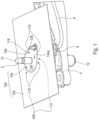
- a first embodiment 100 of a cowl assembly according to the present disclosure.
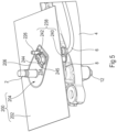
- Figs. 1 and 2 show the cowl assembly 100 together with a pivot shaft 2, a shaft supporting member 4, a washer fluid hose 6 and a hose clip 8.
- the pivot shaft 2 is made for pivoting a windshield wiper in a reciprocating manner. To that end, the head of a windshield wiper arm may be attached to the top end 10 of the pivot shaft 2. The base 12 of the pivot shaft 2 is received in the shaft supporting member 4.
- the washer fluid hose 6 is secured to the shaft supporting member 4 via the hose clip 8.
- the cowl assembly 100 comprises a protective cowl panel 102 and a hose connector 104.
- the protective cowl panel 102 is adapted to be mounted on the bodywork of a vehicle at the lower end of the vehicle's windshield.
- the cowl panel 102 has a shaft opening 106.
- the pivot shaft 2 extends through the shaft opening 106.
- the shaft opening 106 has a circumferential border area 108.
- a front side 110 of the border area 108 is visible in Fig.1
- a back side 112 of the border area 108 is visible in Fig. 2 .
- the front side 110 of the border are 108 defines a circumferential bordering surface 114.
- the back side 112 of the border area 108 comprises a circumferential collar 115.
- the hose connector 104 is set into the shaft opening 106 of the cowl panel 102. Accordingly, the hose connector 104 is bordered by the circumferential border area 108 of the shaft opening 106.
- a front face 116 of the hose connector 104 is flush with the circumferential bordering surface 114 defined by the front side 110 of the border area 108.
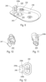
- the hose connector 104 is shown on its own in Figs. 3 and 4 . It may be made of a rigid material, such as rigid plastic.
- the front face 116 of the hose connector 104 is visible in Fig. 3
- a back face 118 of the hose connector 104 is visible in Fig. 4 .
- the hose connector 104 has a through-hole 120 for receiving the pivot shaft 2.
- the outer circumference 122 of the hose connector 104 may be fitted with a watertight seal. This seal may be made of rubber.
- the hose connector 104 has a fluid inlet port 124 on its back face 118 and a fluid outlet port 126 on its front face 116.
- the washer fluid hose 6 is connected to the fluid inlet port 124.
- another washer fluid hose which is secured to a windshield wiper to be attached to the pivot shaft 2, may be connected to the fluid outlet port 126.
- a check-valve may be arranged in the fluid inlet port 124. The purpose of such a check-valve is to prevent a backward flow of washer fluid from the fluid outlet port 126 to the fluid inlet port 124.
- the hose connector 104 consists of a plate-shaped main body 128 and an integral fluid tube 130 fastened to the main body 128.
- the fluid inlet port 124 and the fluid outlet port 126 are both part of the fluid tube 130.
- the fluid tube 130 traverses the front face 116 and the back face 118 of the hose connector 104.
- the fluid tube 130 is removably fastened in a fastening hole 132, which is formed in the main body 128.
- the main body 128 has a base plate 134 and an outer circumferential skirt 136 surrounding the base plate 134.
- the base plate 134 has a front surface 134a and a back surface 134b.
- the front surface 134a of the base plate 134 delimits the extent of the front face 116 of the hose connector 104.
- the base plate 134 is drop-shaped.
- the circumferential collar 115 of the cowl panel's opening 106 surrounds the outer circumferential skirt 136 of the hose connector 104.
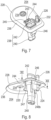
- the hose connector 204 doubles as an electrical connector.
- This embodiment is dedicated to heated nozzle windshield wipers, i.e. nozzle windshield wipers, which have an integrated electrical heating device.
- the heating device improves the cleaning action of the nozzle windshield wiper during winter times.
- the hose connector 204 has an electrical interface 238.
- the electrical interface 238 allows to connect the electrical wiring of the heating device of a heated windshield wiper to an electrical power source behind the cowl panel 202.
- the electrical interface is a plug-and-socket assembly 238 with an electrical socket 240 and an electrical plug 242 received in the electrical socket 240.
- an aperture 244 having an edge 243 is formed in the main body 228 of the hose connector 204.
- the plug-and-socket assembly 238 is mounted in this aperture 244.
- the aperture 244 and the fastening hole 232 are preferably arranged side by side.
- the plug-and-socket assembly 238 does not take up the whole space defined by the aperture 244. Rather, there is a residual clearance 245 between the electrical plug 242 and the edge 243 of the aperture 244. This clearance 245 gives access to a latching clip 247 of the electrical plug 242 (cf. Fig. 10 ). Thanks to the clearance 245, the clip 247 can be unlatched from the electrical socket 240 and the plug 242 unplugged.
- the main body 228 also has a mounting lug 246, which is located next to the aperture 244, and which protrudes from the base plate 234.
- the electrical socket 240 is mounted on the mounting lug 246.
- the corresponding mounting joint may consist of a mounting rail 248a and a pair of mounting brackets 248b clasping the mounting rail 248a, cf. Fig. 12 .
- the mounting brackets 248b are part of the electrical socket 240, and the mounting rail 248a is arranged on the mounting lug 246. This could of course be interchanged.
- Cowl assembly with washer fluid transit - illustrative example
- Figs. 13 and 14 show a cowl assembly 300 with a cowl panel 302 and a hose connector 304.
- the hose connector 304 is surrounded by a circumferential ridge 350 formed in the cowl panel 302. This creates a depression 352, the bottom of which is taken up by the hose connector 304.
- a scupper 354 in the hose connector 304 ensures that rainwater is evacuated from the depression 352 so that it cannot accumulate therein.
- the hose connector 304 also has a mounting stud 356, which is inserted in a corresponding holding fixture 358 formed in the shaft supporting member 4.
- the cowl assemblies of the present disclosure simplify the assembly of the windshield wiper system.
- washer fluid hoses, and, if applicable, electrical wires can be connected with ease.
- the cowl assemblies also have a slim design, which is particularly suited for passenger cars.
- cowl assemblies also have good rainwater deflection properties.
Landscapes
- Engineering & Computer Science (AREA)
- Mechanical Engineering (AREA)
- Water Supply & Treatment (AREA)
- Chemical & Material Sciences (AREA)
- Combustion & Propulsion (AREA)
- Transportation (AREA)
- Body Structure For Vehicles (AREA)
Claims (12)
- Windschutzscheibenwischerhaubenanordnung (100) eines Fahrzeugs, die Folgendes umfasst:a. ein schützendes Windlaufblech (102), dazu angepasst, an der Karosserie eines Fahrzeugs am unteren Ende der Windschutzscheibe des Fahrzeugs montiert zu werden, wobei das Windlaufblech (102) eine Wellenöffnung (106) für die Schwenkachse (2) eines Windschutzscheibenwischers aufweist, wobei die Wellenöffnung (106) einen umlaufenden Randbereich (108) mit einer Vorderseite (110) und einer Rückseite (112) aufweist, wobei die Vorderseite des Randbereichs (110) eine umlaufende Randfläche (114) definiert; undb. einen Schlauchanschluss (104) mit einer Vorderseite (116) und einer Grundplatte (134), wobei eine vordere Fläche (134a) der Grundplatte bündig mit der umlaufenden Randfläche (114) ist, die durch die Vorderseite (110) des Randbereichs definiert ist, und die Ausdehnung der Vorderseite (116) des Schlauchanschlusses begrenzt; und einer Rückseite (118) mit einer äußeren umlaufenden Schürze (136), die die Grundplatte (134) umgibt, wobei der Schlauchanschluss in die Wellenöffnung (106) des Windlaufblechs gesetzt ist, so dass der Schlauchanschluss (104) durch die umlaufende Randfläche der Wellenöffnung (108) begrenzt wird;wobei die Vorderseite (116) des Schlauchanschlusses (104) bündig mit der durch die Vorderseite des Randbereichs (110) definierten umlaufenden Randfläche (114) ist, dadurch gekennzeichnet, dass die Rückseite des Randbereichs (112) der Windlaufblechwellenöffnung (106) einen umlaufenden Kragen (115) aufweist, der die äußere umlaufende Schürze (136) des Schlauchanschlusses umgibt.
- Haubenanordnung (100) nach Anspruch 1, wobei der Schlauchanschluss (104) ein Durchgangsloch (120) zur Aufnahme der Schwenkachse (2) eines Windschutzscheibenwischers aufweist.
- Haubenanordnung (100) nach einem der vorhergehenden Ansprüche, wobei der äußere Umfang (122) des Schlauchanschlusses (104) mit einer wasserdichten Dichtung versehen ist, die vorzugsweise aus Gummi besteht.
- Haubenanordnung (100) nach einem der vorhergehenden Ansprüche, wobei der Schlauchanschluss (104) aus einem starren Material, wie z. B. starrem Kunststoff, besteht.
- Haubenanordnung (100) nach einem der vorhergehenden Ansprüche, wobei der Schlauchanschluss (104) eine Fluideinlassöffnung (124) auf seiner Rückseite (118) und eine Fluidauslassöffnung (126) auf seiner Vorderseite (116) aufweist, wobei beide Öffnungen dazu angepasst sind, einen Scheibenwaschflüssigkeitsschlauchs (6) damit zu verbinden.
- Haubenanordnung (100) nach Anspruch 5, wobei ein Rückschlagventil in der Fluideinlassöffnung (124) angeordnet ist, wobei das Rückschlagventil einen Rückfluss von Scheibenwaschflüssigkeit von der Fluidauslassöffnung zur Fluideinlassöffnung verhindert.
- Haubenanordnung (100) nach Anspruch 5 oder 6, wobei die Fluideinlassöffnung (124) und die Fluidauslassöffnung (126) beide Teil eines integrierten Fluidrohrs (130) sind, das die Vorder- und Rückseite des Schlauchanschlusses (104) durchquert, wobei vorzugsweise der Schlauchanschluss ein Befestigungsloch (132) aufweist und das Fluidrohr (130) im Befestigungsloch entfernbar befestigt ist.
- Haubenanordnung (200) nach einem der vorhergehenden Ansprüche, wobei der Schlauchanschluss (204) auch ein elektrischer Verbinder ist, der eine elektrische Schnittstelle (238) aufweist, die es ermöglicht, die elektrische Verkabelung einer elektrischen Heizvorrichtung eines beheizten Windschutzscheibenwischers mit einer elektrischen Stromquelle hinter dem Windlaufblech (202) zu verbinden.
- Haubenanordnung (200) nach Anspruch 8, wobei die elektrische Schnittstelle eine Stecker-und-Buchsen-Anordnung (238) mit einer elektrischen Buchse (240) und einem elektrischen Stecker (242) ist, der in der elektrischen Buchse (240) aufgenommen wird.
- Haubenanordnung (200) nach Anspruch 9, wobei die Stecker-und-Buchsen-Anordnung in einer Öffnung (244) montiert ist, die in dem Schlauchanschluss ausgebildet ist.
- Haubenanordnung (200) nach Anspruch 9 oder 10, wobei der Schlauchanschluss (204) eine Befestigungslasche (246) aufweist und die elektrische Buchse (240) an der Befestigungslasche montiert ist, vorzugsweise über eine Verbindung aus einer Befestigungsschiene (248a) und einem Paar von Befestigungsbügeln (248b), die die Befestigungsschiene umschließen.
- Kraftfahrzeug, das die Haubenanordnung (100, 200) nach einem der vorhergehenden Ansprüche umfasst.
Priority Applications (4)
| Application Number | Priority Date | Filing Date | Title |
|---|---|---|---|
| EP21188874.8A EP4124517B1 (de) | 2021-07-30 | 2021-07-30 | Windschutzscheibenwischerhaubenanordnung mit einem bündig montierten eingesetzten schlauchverbinder |
| CN202280053320.6A CN117769508A (zh) | 2021-07-30 | 2022-07-26 | 带有齐平安装的嵌入式软管连接件的挡风玻璃雨刮器围罩组件 |
| US18/291,322 US20250115303A1 (en) | 2021-07-30 | 2022-07-26 | Windshield wiper cowl assembly with a flush-mounted inset hose connector |
| PCT/EP2022/070933 WO2023006740A1 (en) | 2021-07-30 | 2022-07-26 | A windshield wiper cowl assembly with a flush-mounted inset hose connector |
Applications Claiming Priority (1)
| Application Number | Priority Date | Filing Date | Title |
|---|---|---|---|
| EP21188874.8A EP4124517B1 (de) | 2021-07-30 | 2021-07-30 | Windschutzscheibenwischerhaubenanordnung mit einem bündig montierten eingesetzten schlauchverbinder |
Publications (2)
| Publication Number | Publication Date |
|---|---|
| EP4124517A1 EP4124517A1 (de) | 2023-02-01 |
| EP4124517B1 true EP4124517B1 (de) | 2024-11-20 |
Family
ID=77167988
Family Applications (1)
| Application Number | Title | Priority Date | Filing Date |
|---|---|---|---|
| EP21188874.8A Active EP4124517B1 (de) | 2021-07-30 | 2021-07-30 | Windschutzscheibenwischerhaubenanordnung mit einem bündig montierten eingesetzten schlauchverbinder |
Country Status (4)
| Country | Link |
|---|---|
| US (1) | US20250115303A1 (de) |
| EP (1) | EP4124517B1 (de) |
| CN (1) | CN117769508A (de) |
| WO (1) | WO2023006740A1 (de) |
Family Cites Families (20)
| Publication number | Priority date | Publication date | Assignee | Title |
|---|---|---|---|---|
| US2627011A (en) * | 1949-04-05 | 1953-01-27 | William C Eaves | Heating device for window cleaners |
| US2869166A (en) * | 1956-04-12 | 1959-01-20 | William C Eaves | Heating or deicing unit for glazed windows |
| US3910652A (en) * | 1974-03-29 | 1975-10-07 | Trico Products Corp | Self-dimensioning bearing assembly |
| JPH0544217Y2 (de) * | 1987-07-08 | 1993-11-09 | ||
| FI85356C (fi) * | 1989-12-13 | 1992-04-10 | Keijo Vornanen | Tork- och tvaettanordning foer vindrutan i ett fordon. |
| US5203049A (en) * | 1991-05-20 | 1993-04-20 | Jidosha Denki Kogyo Kabushiki Kaisha | Wiper apparatus with mechanism for switching spraying direction of washing fluid |
| DE19501210A1 (de) * | 1995-01-17 | 1996-07-18 | Teves Gmbh Alfred | Modul für ein Kraftfahrzeug |
| FR2733473B1 (fr) * | 1995-04-28 | 1997-06-06 | Valeo Systemes Dessuyage | Mecanisme d'essuie-glace comportant des moyens d'etancheite perfectionnes |
| JP3634303B2 (ja) * | 2001-12-12 | 2005-03-30 | 本田技研工業株式会社 | 車両用エネルギー吸収ワイパー構造 |
| US6742827B1 (en) * | 2002-11-27 | 2004-06-01 | Valeo Electrical Systems, Inc. | Plug-n-play module with integral motor connector |
| US6981737B2 (en) * | 2003-11-26 | 2006-01-03 | Denso International America, Inc. | Double plate heater pipe seal to dash |
| JP5347313B2 (ja) * | 2008-04-18 | 2013-11-20 | スズキ株式会社 | 車両のカウル部構造 |
| JP2010012815A (ja) | 2008-07-01 | 2010-01-21 | Mitsuba Corp | ワイパ装置 |
| DE102008063112A1 (de) * | 2008-12-24 | 2009-09-03 | Daimler Ag | Scheibenwischeranordnung für eine Scheibe, insbesondere eine Windschutzscheibe, eines Kraftwagens |
| US8840173B2 (en) * | 2011-07-11 | 2014-09-23 | Nissan North America, Inc. | Water shield for a wiper drive assembly |
| US8641130B2 (en) * | 2011-09-23 | 2014-02-04 | Nissan North America, Inc. | Vehicle cowl cover |
| CN102935836B (zh) * | 2012-11-20 | 2015-06-10 | 奇瑞汽车股份有限公司 | 轿车后风挡清洗装置及轿车 |
| DE102012222044B4 (de) * | 2012-12-03 | 2025-02-13 | Continental Automotive Technologies GmbH | Hydraulisches Reinigungssystem |
| CN103600725B (zh) * | 2013-11-14 | 2016-03-16 | 奇瑞汽车股份有限公司 | 一种车辆后风挡玻璃清洗装置及车辆 |
| FR3064232B1 (fr) * | 2017-03-27 | 2021-06-04 | Valeo Systemes Dessuyage | Capuchon et bras porte-balai d'essuie-glace pour vehicule automobile |
-
2021
- 2021-07-30 EP EP21188874.8A patent/EP4124517B1/de active Active
-
2022
- 2022-07-26 WO PCT/EP2022/070933 patent/WO2023006740A1/en not_active Ceased
- 2022-07-26 US US18/291,322 patent/US20250115303A1/en active Pending
- 2022-07-26 CN CN202280053320.6A patent/CN117769508A/zh active Pending
Also Published As
| Publication number | Publication date |
|---|---|
| CN117769508A (zh) | 2024-03-26 |
| EP4124517A1 (de) | 2023-02-01 |
| US20250115303A1 (en) | 2025-04-10 |
| WO2023006740A1 (en) | 2023-02-02 |
Similar Documents
| Publication | Publication Date | Title |
|---|---|---|
| US7895703B2 (en) | Backdoor apparatus | |
| EP0995651B1 (de) | Zusammenschnappbare Scheibenwaschdüse | |
| CN104428178B (zh) | 具有液压连接器的擦拭器刮片 | |
| US20220212632A1 (en) | Wind deflector for a windscreen wiper system of a motor vehicle | |
| US7316447B2 (en) | Integrated motor vehicle cowl vent and seal | |
| EP4124517B1 (de) | Windschutzscheibenwischerhaubenanordnung mit einem bündig montierten eingesetzten schlauchverbinder | |
| US8840173B2 (en) | Water shield for a wiper drive assembly | |
| CN101362457B (zh) | 洗涤器喷嘴 | |
| JP2004501826A (ja) | ウインドシールドワイパのためのリンク部分 | |
| CN108657128B (zh) | 用于自主车辆的风挡玻璃雨刮臂和帽 | |
| CN201321019Y (zh) | 喷嘴及具有所述喷嘴的洗涤器 | |
| US11858474B2 (en) | Wind deflector for a window wiper system of a motor vehicle | |
| JP3866351B2 (ja) | 自動車のフードシール取付構造 | |
| US20230356695A1 (en) | Wind deflector for a windscreen wiper system of a motor vehicle | |
| CN219096824U (zh) | 一种通风盖板及车辆 | |
| JPS5942293Y2 (ja) | リアウインドガラス用洗浄液噴射装置 | |
| JP7649473B2 (ja) | 車両前部構造 | |
| JP3678055B2 (ja) | 車両の前部車体構造 | |
| KR0126085B1 (ko) | 차량카울부의 취부구조 | |
| KR102681052B1 (ko) | 와이퍼 장착용 와셔노즐 | |
| JP7688133B2 (ja) | ワイパーアーム、ワイパー及び車両 | |
| US20250360968A1 (en) | Vehicle fluid management assembly | |
| CN214689396U (zh) | 一种刮臂、刮水器和车辆 | |
| JPS5943340B2 (ja) | 車両用ウオツシヤノズルの取付構造 | |
| CN210139853U (zh) | 清洗装置及汽车 |
Legal Events
| Date | Code | Title | Description |
|---|---|---|---|
| PUAI | Public reference made under article 153(3) epc to a published international application that has entered the european phase |
Free format text: ORIGINAL CODE: 0009012 |
|
| STAA | Information on the status of an ep patent application or granted ep patent |
Free format text: STATUS: THE APPLICATION HAS BEEN PUBLISHED |
|
| AK | Designated contracting states |
Kind code of ref document: A1 Designated state(s): AL AT BE BG CH CY CZ DE DK EE ES FI FR GB GR HR HU IE IS IT LI LT LU LV MC MK MT NL NO PL PT RO RS SE SI SK SM TR |
|
| STAA | Information on the status of an ep patent application or granted ep patent |
Free format text: STATUS: REQUEST FOR EXAMINATION WAS MADE |
|
| 17P | Request for examination filed |
Effective date: 20230731 |
|
| RBV | Designated contracting states (corrected) |
Designated state(s): AL AT BE BG CH CY CZ DE DK EE ES FI FR GB GR HR HU IE IS IT LI LT LU LV MC MK MT NL NO PL PT RO RS SE SI SK SM TR |
|
| GRAP | Despatch of communication of intention to grant a patent |
Free format text: ORIGINAL CODE: EPIDOSNIGR1 |
|
| STAA | Information on the status of an ep patent application or granted ep patent |
Free format text: STATUS: GRANT OF PATENT IS INTENDED |
|
| RIC1 | Information provided on ipc code assigned before grant |
Ipc: B62D 25/08 20060101ALI20240507BHEP Ipc: B60S 1/48 20060101ALI20240507BHEP Ipc: B60S 1/34 20060101AFI20240507BHEP |
|
| INTG | Intention to grant announced |
Effective date: 20240610 |
|
| GRAS | Grant fee paid |
Free format text: ORIGINAL CODE: EPIDOSNIGR3 |
|
| GRAA | (expected) grant |
Free format text: ORIGINAL CODE: 0009210 |
|
| STAA | Information on the status of an ep patent application or granted ep patent |
Free format text: STATUS: THE PATENT HAS BEEN GRANTED |
|
| AK | Designated contracting states |
Kind code of ref document: B1 Designated state(s): AL AT BE BG CH CY CZ DE DK EE ES FI FR GB GR HR HU IE IS IT LI LT LU LV MC MK MT NL NO PL PT RO RS SE SI SK SM TR |
|
| REG | Reference to a national code |
Ref country code: GB Ref legal event code: FG4D |
|
| REG | Reference to a national code |
Ref country code: CH Ref legal event code: EP |
|
| REG | Reference to a national code |
Ref country code: DE Ref legal event code: R096 Ref document number: 602021021997 Country of ref document: DE |
|
| REG | Reference to a national code |
Ref country code: IE Ref legal event code: FG4D |
|
| REG | Reference to a national code |
Ref country code: LT Ref legal event code: MG9D |
|
| REG | Reference to a national code |
Ref country code: NL Ref legal event code: MP Effective date: 20241120 |
|
| PG25 | Lapsed in a contracting state [announced via postgrant information from national office to epo] |
Ref country code: HR Free format text: LAPSE BECAUSE OF FAILURE TO SUBMIT A TRANSLATION OF THE DESCRIPTION OR TO PAY THE FEE WITHIN THE PRESCRIBED TIME-LIMIT Effective date: 20241120 Ref country code: IS Free format text: LAPSE BECAUSE OF FAILURE TO SUBMIT A TRANSLATION OF THE DESCRIPTION OR TO PAY THE FEE WITHIN THE PRESCRIBED TIME-LIMIT Effective date: 20250320 Ref country code: PT Free format text: LAPSE BECAUSE OF FAILURE TO SUBMIT A TRANSLATION OF THE DESCRIPTION OR TO PAY THE FEE WITHIN THE PRESCRIBED TIME-LIMIT Effective date: 20250320 |
|
| PG25 | Lapsed in a contracting state [announced via postgrant information from national office to epo] |
Ref country code: FI Free format text: LAPSE BECAUSE OF FAILURE TO SUBMIT A TRANSLATION OF THE DESCRIPTION OR TO PAY THE FEE WITHIN THE PRESCRIBED TIME-LIMIT Effective date: 20241120 Ref country code: NL Free format text: LAPSE BECAUSE OF FAILURE TO SUBMIT A TRANSLATION OF THE DESCRIPTION OR TO PAY THE FEE WITHIN THE PRESCRIBED TIME-LIMIT Effective date: 20241120 |
|
| REG | Reference to a national code |
Ref country code: AT Ref legal event code: MK05 Ref document number: 1743317 Country of ref document: AT Kind code of ref document: T Effective date: 20241120 |
|
| PG25 | Lapsed in a contracting state [announced via postgrant information from national office to epo] |
Ref country code: BG Free format text: LAPSE BECAUSE OF FAILURE TO SUBMIT A TRANSLATION OF THE DESCRIPTION OR TO PAY THE FEE WITHIN THE PRESCRIBED TIME-LIMIT Effective date: 20241120 |
|
| PG25 | Lapsed in a contracting state [announced via postgrant information from national office to epo] |
Ref country code: ES Free format text: LAPSE BECAUSE OF FAILURE TO SUBMIT A TRANSLATION OF THE DESCRIPTION OR TO PAY THE FEE WITHIN THE PRESCRIBED TIME-LIMIT Effective date: 20241120 |
|
| PG25 | Lapsed in a contracting state [announced via postgrant information from national office to epo] |
Ref country code: NO Free format text: LAPSE BECAUSE OF FAILURE TO SUBMIT A TRANSLATION OF THE DESCRIPTION OR TO PAY THE FEE WITHIN THE PRESCRIBED TIME-LIMIT Effective date: 20250220 |
|
| PG25 | Lapsed in a contracting state [announced via postgrant information from national office to epo] |
Ref country code: LV Free format text: LAPSE BECAUSE OF FAILURE TO SUBMIT A TRANSLATION OF THE DESCRIPTION OR TO PAY THE FEE WITHIN THE PRESCRIBED TIME-LIMIT Effective date: 20241120 Ref country code: AT Free format text: LAPSE BECAUSE OF FAILURE TO SUBMIT A TRANSLATION OF THE DESCRIPTION OR TO PAY THE FEE WITHIN THE PRESCRIBED TIME-LIMIT Effective date: 20241120 Ref country code: GR Free format text: LAPSE BECAUSE OF FAILURE TO SUBMIT A TRANSLATION OF THE DESCRIPTION OR TO PAY THE FEE WITHIN THE PRESCRIBED TIME-LIMIT Effective date: 20250221 |
|
| PG25 | Lapsed in a contracting state [announced via postgrant information from national office to epo] |
Ref country code: PL Free format text: LAPSE BECAUSE OF FAILURE TO SUBMIT A TRANSLATION OF THE DESCRIPTION OR TO PAY THE FEE WITHIN THE PRESCRIBED TIME-LIMIT Effective date: 20241120 |
|
| PG25 | Lapsed in a contracting state [announced via postgrant information from national office to epo] |
Ref country code: RS Free format text: LAPSE BECAUSE OF FAILURE TO SUBMIT A TRANSLATION OF THE DESCRIPTION OR TO PAY THE FEE WITHIN THE PRESCRIBED TIME-LIMIT Effective date: 20250220 |
|
| PG25 | Lapsed in a contracting state [announced via postgrant information from national office to epo] |
Ref country code: SM Free format text: LAPSE BECAUSE OF FAILURE TO SUBMIT A TRANSLATION OF THE DESCRIPTION OR TO PAY THE FEE WITHIN THE PRESCRIBED TIME-LIMIT Effective date: 20241120 |
|
| PG25 | Lapsed in a contracting state [announced via postgrant information from national office to epo] |
Ref country code: DK Free format text: LAPSE BECAUSE OF FAILURE TO SUBMIT A TRANSLATION OF THE DESCRIPTION OR TO PAY THE FEE WITHIN THE PRESCRIBED TIME-LIMIT Effective date: 20241120 |
|
| PG25 | Lapsed in a contracting state [announced via postgrant information from national office to epo] |
Ref country code: EE Free format text: LAPSE BECAUSE OF FAILURE TO SUBMIT A TRANSLATION OF THE DESCRIPTION OR TO PAY THE FEE WITHIN THE PRESCRIBED TIME-LIMIT Effective date: 20241120 |
|
| PG25 | Lapsed in a contracting state [announced via postgrant information from national office to epo] |
Ref country code: RO Free format text: LAPSE BECAUSE OF FAILURE TO SUBMIT A TRANSLATION OF THE DESCRIPTION OR TO PAY THE FEE WITHIN THE PRESCRIBED TIME-LIMIT Effective date: 20241120 |
|
| PG25 | Lapsed in a contracting state [announced via postgrant information from national office to epo] |
Ref country code: SK Free format text: LAPSE BECAUSE OF FAILURE TO SUBMIT A TRANSLATION OF THE DESCRIPTION OR TO PAY THE FEE WITHIN THE PRESCRIBED TIME-LIMIT Effective date: 20241120 |
|
| PG25 | Lapsed in a contracting state [announced via postgrant information from national office to epo] |
Ref country code: CZ Free format text: LAPSE BECAUSE OF FAILURE TO SUBMIT A TRANSLATION OF THE DESCRIPTION OR TO PAY THE FEE WITHIN THE PRESCRIBED TIME-LIMIT Effective date: 20241120 |
|
| PG25 | Lapsed in a contracting state [announced via postgrant information from national office to epo] |
Ref country code: IT Free format text: LAPSE BECAUSE OF FAILURE TO SUBMIT A TRANSLATION OF THE DESCRIPTION OR TO PAY THE FEE WITHIN THE PRESCRIBED TIME-LIMIT Effective date: 20241120 |
|
| REG | Reference to a national code |
Ref country code: DE Ref legal event code: R097 Ref document number: 602021021997 Country of ref document: DE |
|
| PG25 | Lapsed in a contracting state [announced via postgrant information from national office to epo] |
Ref country code: SE Free format text: LAPSE BECAUSE OF FAILURE TO SUBMIT A TRANSLATION OF THE DESCRIPTION OR TO PAY THE FEE WITHIN THE PRESCRIBED TIME-LIMIT Effective date: 20241120 |
|
| PLBE | No opposition filed within time limit |
Free format text: ORIGINAL CODE: 0009261 |
|
| STAA | Information on the status of an ep patent application or granted ep patent |
Free format text: STATUS: NO OPPOSITION FILED WITHIN TIME LIMIT |
|
| PGFP | Annual fee paid to national office [announced via postgrant information from national office to epo] |
Ref country code: DE Payment date: 20250711 Year of fee payment: 5 |
|
| PGFP | Annual fee paid to national office [announced via postgrant information from national office to epo] |
Ref country code: FR Payment date: 20250730 Year of fee payment: 5 |
|
| 26N | No opposition filed |
Effective date: 20250821 |