EP4123817B1 - Befestigungselement, batterie sowie verfahren zur herstellung einer batterie - Google Patents
Befestigungselement, batterie sowie verfahren zur herstellung einer batterie Download PDFInfo
- Publication number
- EP4123817B1 EP4123817B1 EP21908115.5A EP21908115A EP4123817B1 EP 4123817 B1 EP4123817 B1 EP 4123817B1 EP 21908115 A EP21908115 A EP 21908115A EP 4123817 B1 EP4123817 B1 EP 4123817B1
- Authority
- EP
- European Patent Office
- Prior art keywords
- top cover
- workpiece
- base
- clamping
- limiting part
- Prior art date
- Legal status (The legal status is an assumption and is not a legal conclusion. Google has not performed a legal analysis and makes no representation as to the accuracy of the status listed.)
- Active
Links
Images


Classifications
-
- B—PERFORMING OPERATIONS; TRANSPORTING
- B60—VEHICLES IN GENERAL
- B60R—VEHICLES, VEHICLE FITTINGS, OR VEHICLE PARTS, NOT OTHERWISE PROVIDED FOR
- B60R16/00—Electric or fluid circuits specially adapted for vehicles and not otherwise provided for; Arrangement of elements of electric or fluid circuits specially adapted for vehicles and not otherwise provided for
- B60R16/02—Electric or fluid circuits specially adapted for vehicles and not otherwise provided for; Arrangement of elements of electric or fluid circuits specially adapted for vehicles and not otherwise provided for electric constitutive elements
- B60R16/0207—Wire harnesses
- B60R16/0215—Protecting, fastening and routing means therefor
-
- H—ELECTRICITY
- H01—ELECTRIC ELEMENTS
- H01M—PROCESSES OR MEANS, e.g. BATTERIES, FOR THE DIRECT CONVERSION OF CHEMICAL ENERGY INTO ELECTRICAL ENERGY
- H01M10/00—Secondary cells; Manufacture thereof
- H01M10/04—Construction or manufacture in general
-
- H—ELECTRICITY
- H01—ELECTRIC ELEMENTS
- H01M—PROCESSES OR MEANS, e.g. BATTERIES, FOR THE DIRECT CONVERSION OF CHEMICAL ENERGY INTO ELECTRICAL ENERGY
- H01M10/00—Secondary cells; Manufacture thereof
- H01M10/05—Accumulators with non-aqueous electrolyte
- H01M10/052—Li-accumulators
- H01M10/0525—Rocking-chair batteries, i.e. batteries with lithium insertion or intercalation in both electrodes; Lithium-ion batteries
-
- H—ELECTRICITY
- H01—ELECTRIC ELEMENTS
- H01M—PROCESSES OR MEANS, e.g. BATTERIES, FOR THE DIRECT CONVERSION OF CHEMICAL ENERGY INTO ELECTRICAL ENERGY
- H01M50/00—Constructional details or processes of manufacture of the non-active parts of electrochemical cells other than fuel cells, e.g. hybrid cells
- H01M50/20—Mountings; Secondary casings or frames; Racks, modules or packs; Suspension devices; Shock absorbers; Transport or carrying devices; Holders
- H01M50/244—Secondary casings; Racks; Suspension devices; Carrying devices; Holders characterised by their mounting method
-
- H—ELECTRICITY
- H01—ELECTRIC ELEMENTS
- H01M—PROCESSES OR MEANS, e.g. BATTERIES, FOR THE DIRECT CONVERSION OF CHEMICAL ENERGY INTO ELECTRICAL ENERGY
- H01M50/00—Constructional details or processes of manufacture of the non-active parts of electrochemical cells other than fuel cells, e.g. hybrid cells
- H01M50/20—Mountings; Secondary casings or frames; Racks, modules or packs; Suspension devices; Shock absorbers; Transport or carrying devices; Holders
- H01M50/262—Mountings; Secondary casings or frames; Racks, modules or packs; Suspension devices; Shock absorbers; Transport or carrying devices; Holders with fastening means, e.g. locks
- H01M50/264—Mountings; Secondary casings or frames; Racks, modules or packs; Suspension devices; Shock absorbers; Transport or carrying devices; Holders with fastening means, e.g. locks for cells or batteries, e.g. straps, tie rods or peripheral frames
-
- H—ELECTRICITY
- H01—ELECTRIC ELEMENTS
- H01M—PROCESSES OR MEANS, e.g. BATTERIES, FOR THE DIRECT CONVERSION OF CHEMICAL ENERGY INTO ELECTRICAL ENERGY
- H01M50/00—Constructional details or processes of manufacture of the non-active parts of electrochemical cells other than fuel cells, e.g. hybrid cells
- H01M50/50—Current conducting connections for cells or batteries
- H01M50/502—Interconnectors for connecting terminals of adjacent batteries; Interconnectors for connecting cells outside a battery casing
- H01M50/505—Interconnectors for connecting terminals of adjacent batteries; Interconnectors for connecting cells outside a battery casing comprising a single busbar
-
- H—ELECTRICITY
- H01—ELECTRIC ELEMENTS
- H01M—PROCESSES OR MEANS, e.g. BATTERIES, FOR THE DIRECT CONVERSION OF CHEMICAL ENERGY INTO ELECTRICAL ENERGY
- H01M50/00—Constructional details or processes of manufacture of the non-active parts of electrochemical cells other than fuel cells, e.g. hybrid cells
- H01M50/50—Current conducting connections for cells or batteries
- H01M50/502—Interconnectors for connecting terminals of adjacent batteries; Interconnectors for connecting cells outside a battery casing
- H01M50/514—Methods for interconnecting adjacent batteries or cells
- H01M50/517—Methods for interconnecting adjacent batteries or cells by fixing means, e.g. screws, rivets or bolts
-
- H—ELECTRICITY
- H01—ELECTRIC ELEMENTS
- H01M—PROCESSES OR MEANS, e.g. BATTERIES, FOR THE DIRECT CONVERSION OF CHEMICAL ENERGY INTO ELECTRICAL ENERGY
- H01M2220/00—Batteries for particular applications
- H01M2220/20—Batteries in motive systems, e.g. vehicle, ship, plane
-
- Y—GENERAL TAGGING OF NEW TECHNOLOGICAL DEVELOPMENTS; GENERAL TAGGING OF CROSS-SECTIONAL TECHNOLOGIES SPANNING OVER SEVERAL SECTIONS OF THE IPC; TECHNICAL SUBJECTS COVERED BY FORMER USPC CROSS-REFERENCE ART COLLECTIONS [XRACs] AND DIGESTS
- Y02—TECHNOLOGIES OR APPLICATIONS FOR MITIGATION OR ADAPTATION AGAINST CLIMATE CHANGE
- Y02E—REDUCTION OF GREENHOUSE GAS [GHG] EMISSIONS, RELATED TO ENERGY GENERATION, TRANSMISSION OR DISTRIBUTION
- Y02E60/00—Enabling technologies; Technologies with a potential or indirect contribution to GHG emissions mitigation
- Y02E60/10—Energy storage using batteries
Definitions
- the application relates to the technical field of batteries, and more particularly relates to a fixing member, a battery, an electric device, and a method and system for manufacturing the battery.
- Battery cells are widely used in electronic devices such as mobile phones, laptops, battery cars, electric vehicles, electric aircrafts, electric boats, electric toy cars, electric toy boats, electric toy planes, electric tools, etc.
- Battery cells can include nickel-cadmium battery cells, nickel-hydrogen battery cells, lithium ion battery cells and secondary alkaline zinc-manganese battery cells.
- JP2012138333 (A ) teaches a busbar holder 4 which is formed by a body part 7 having busbar storage portions 15 capable of storing busbars 3, and a lid part 9 connected to the body part 7 by hinges 8.
- the busbars 3 have a clearance in the busbar storage portions 15 permitting a predetermined displacement in the direction of arrangement of batteries 1. If insertion holes 5 in any busbar 3 are not aligned with corresponding electrodes 2, the busbar 3 can be displaced in the arrangement direction to align the insertion holes 5 with the electrodes to be inserted.
- support pieces 6 protruded from the busbar fit in guide portions 16 formed in the body part 7 to support the displacement of the busbar 3.
- WO2010001477A1 discloses an electric wire holder capable of sufficiently functioning without causing an extreme deterioration in its firm sticking with an electric wire even if the kind or the like of the wire is slightly changed.
- the wire holder (1) is formed in a generally cylindrical body installable on the chassis (2) of an electronic appliance.
- a clamp part (20) is formed of an elastic member, and disposed in a support part for supporting the wire (3) inserted into the central opening of the wire holder (1).
- the clamp part (20) holds the wire (3) while drivingly contacting at its tip end against the outer surface of the wire (3).
- the clamp part (20) is electrically conductive to the chassis (2) through the support part.
- JP2005160273A discloses a clip 1 sandwiching and retaining a laminated bus bar 50 which layers two bus bars 52, 53 through an insulation sheet 51, and is the bus bar fixing device for fixing the laminated bus bar 50 in a battery.
- This bus bar fixing device has first and second retaining portions 10, 20 for sandwiching the laminated bus bar 50 so as to face each other, a bent portion 30 for opening/closing the first and second retaining portions 10, 20 for inserting the laminated bus bar 50, and a fixing portion 40 for fixing the clip 1 at a basket body and the like for the battery.
- Portions 11, 21 which are brought into contact with the laminated bus bar 50 at least in the first and second retaining portions 10, 20 are constituted of first synthetic resin material which has excellent heat resistance and prevents thermal deformation.
- the bent portion 30 is constituted of the second synthetic resin material having a lower Young's modulus than the first synthetic resin material and high bent strength.
- a plurality of battery cells are assembled together to form a battery, when used in groups.
- some workpieces contained therein may be easily driven to vibrate, which affects the stability of the battery.
- the application provides a fixing member, a battery, an electric device and a method and system for manufacturing the battery, which can reduce the shaking of a workpiece and improve the stability of the battery.
- the application provides a fixing member for fixing a workpiece as defined in claim 1, preferred embodiments are defined in dependent claims 2-11, which includes:
- the first elastic member can abut against the workpiece in the first direction to fix the workpiece in the first direction
- the second elastic member can abut against the workpiece in the second direction to fix the workpiece in the second direction.
- the fixing member according to an embodiment of the application may fix the workpiece in the first direction and the second direction, thereby improving the stability of the workpiece, reducing the risk of joint failure of the workpiece and the battery cell and improving the working performance of the battery.
- the fixing member can realize the movement of the workpiece and reduce the difficulty of adjusting the position of the workpiece.
- the application provides a method for manufacturing a battery as defined in claim 13.
- battery cells may include a lithium ion secondary battery cell, a lithium ion primary battery cell, a lithium-sulfur battery, a sodium lithium-ion battery cell, a sodium ion battery cell, a magnesium ion battery cell, etc., which are not limited by the embodiments of the application.
- the battery cell may be in cylindrical, flat, cuboid or other shapes, which is not limited by the embodiments of the application.
- the battery cells are divided into three types according to packaging manners: cylindrical battery cells, square battery cells and pouch battery cells, which are not limited by the embodiments of the application.
- the positive current collector may be made of aluminum, and the positive active material layer includes a positive active material which may be lithium cobaltate, lithium iron phosphate, ternary lithium or lithium manganate.
- the negative pole piece includes a negative current collector and a negative active material layer coated on a surface of the negative current collector; the negative current collector includes a negative current collecting portion and a negative protrusion portion protruding from the negative current collecting portion, the negative current collecting portion is coated with the negative active material layer, at least part of the negative protrusion portion is not coated with the negative active material layer, and the negative protrusion portion serves as a negative tab.
- the inventors tried to fix the workpiece with a strap, for example, to bind a bus component or cable to other components of the battery, so as to improve the stability of the workpiece and reduce the shaking of the workpiece when the battery vibrates.
- the inventors found it difficult to displace or adjust the position of the workpiece after fastened with a strap; and the strap must be cut off to remove the workpiece, which operation is complicated.
- the electric devices may be vehicles, mobile phones, portable devices, laptops, ships, spacecraft, electric toys and electric tools.
- the vehicles may be fuel vehicles, gas vehicles or new energy vehicles, and the new energy vehicles may be battery electric vehicles, hybrid electric vehicles, extended-range vehicles, etc.
- the spacecrafts include airplanes, rockets, space shuttles, spaceships, etc.
- the electric toys include fixed or mobile electric toys, such as game machines, electric car toys, electric ship toys and electric airplane toys.
- the electric tools include metal cutting electric tools, electric grinding tools, electric assembling tools and electric tools for railways, such as electric drills, electric grinders, electric wrenches, electric screwdrivers, electric hammers, impact electric drills, concrete vibrators, electric planers, etc.
- the embodiment of the application does not impose special restrictions on the above-mentioned electric devices.
- Fig. 1 is a schematic structural diagram of a vehicle provided in some embodiments of the application.
- a battery 2 is disposed inside a vehicle 1, and the battery 2 may be disposed at the bottom, head or tail of the vehicle 1.
- the battery 2 may be used for supplying electricity to the vehicle 1, for example, the battery 2 may be used as an operating power source for the vehicle 1.
- the vehicle 1 may further include a controller 3 and a motor 4, where the controller 3 is used for controlling the battery 2 to supply electricity to the motor 4 to be used for, for example, operating electricity requirements during start-up, navigation and running of the vehicle 1.
- the battery 2 may not only serve as the operating power source for the vehicle 1, but also serve as a driving power source for the vehicle 1, so as to replace or partially replace fuel or natural gas to provide driving power for the vehicle 1.
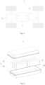
- Fig. 2 is an exploded view of a battery provided in some embodiments of the application. As shown in Fig. 2 , the battery 2 includes a box 5 and a battery cell (not shown in Fig. 2 ), and the battery cell is accommodated in the box 5.
- the box 5 is used for accommodating the battery cell and may be of various structures.
- the box 5 may include a first box portion 51 and a second box portion 52, the first box portion 51 and the second box portion 52 may cover each other, and the first box portion 51 and the second box portion 52 define an accommodation space 53 for accommodating the battery cell together.
- the second box portion 52 may be of a hollow structure with an opening end, the first box portion 51 is of a plate-like structure, and the first box portion 51 covers an opening side of the second box portion 52 so as to form the box 5 with the accommodation space 53.
- the first box portion 51 and the second box portion 52 may be both of hollow structures with opening sides, and an opening side of the first box portion 51 covers the opening side of the second box portion 52 so as to form the box 5 with the accommodation space 53.
- the first box portion 51 and the second box portion 52 may be in various shapes, such as a cylinder or a cuboid.
- a sealing member such as a sealant or a sealing ring, may be arranged between the first box portion 51 and the second box portion 52.
- the first box portion 51 covers a top portion of the second box portion 52
- the first box portion 51 may also be referred to as an upper box cover
- the second box portion 52 may also be referred to as a lower box.
- the battery 2 includes a plurality of battery modules 6, and each of the battery modules 6 includes a plurality of battery cells 61; and the battery 2 further includes a bus component 7, through which the plurality of battery cells 61 in the battery module 6 may be electrically connected, so as to allow the plurality of battery cells 61 in the battery module 6 to be connected in parallel, series or combination thereof.
- the bus component 7 may further be used to connect the plurality of battery modules 6 in series, parallel or combination thereof to form a whole.
- the battery module 6 further includes two end plates 62 and two side plates 63, characterized in that the two end plates 62 are arranged on both ends of the plurality of battery cells 61 in the alignment direction, the two side plates 63 are arranged on both sides of the plurality of battery units 61, the two end plates 62 and the two side plates 63 are fixedly connected to form a substantially rectangular frame for holding the plurality of battery units 61.
- the battery 2 further includes a cable (not shown) electrically connected to the battery cell 61.
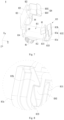
- Fig. 4 is a structural schematic diagram of a fixing member provided in some embodiments of the application
- Fig. 5 is a structural schematic diagram of a fixing member provided in some embodiments of the application when fixing a workpiece
- Fig. 6 is an enlarged view of the fixing member at the round frame A in Fig. 4
- Fig. 7 is a structural schematic diagram of the fixing member in Fig. 4 before clamping.
- the base 81 is installed in the external pedestal, and may be installed in, for example, a box of battery, an end plate, a bracket in a box or other fixed structures. In some embodiments, the base 81 is detachably connected to an external pedestal.
- the top cover 82 may be detachably connected or undetachably connected (e.g., welded) to the base 81.
- the top cover 82 and the base 81 may be independent members or two parts of an integrally formed member, and may be connected by their own structures or by other members (e.g. fasteners).
- the accommodating groove 83 may also be called an accommodating cavity, and is open at both ends.
- the workpiece may pass through the accommodating groove 83 via the opening thereof.
- the top wall 831 and the bottom wall 832 of the accommodating groove 83 are arranged opposite to each other in the first direction X, and may be curved walls or flat walls.
- the top wall 831 and the bottom wall 832 of the accommodating groove 83 are both flat walls and arranged in parallel.
- the top wall 831 and the bottom wall 832 of the accommodating groove 83 are perpendicular to the first direction X.
- the first elastic member 84 When the workpiece passes through the accommodating groove 83, the first elastic member 84 abuts against the workpiece from one side thereof in the first direction X.
- the first elastic member 84 is elastically deformed under the action of the workpiece; correspondingly, the first elastic member 84 applies an elastic force to the workpiece to abut against the workpiece.
- the first elastic member 84 is arranged on one side, close to the top wall 831, of the workpiece in the first direction X, or on one side, close to the bottom wall 832, of the workpiece in the first direction X, or on both sides of the workpiece in the first direction X.
- the first elastic member 84 is arranged on one side, close to the top wall 831, of the workpiece in the first direction X, and abuts against the workpiece, enabling the workpiece to abut against the bottom wall 832 and to be fixed between the first elastic member 84 and the bottom wall 832.
- the first elastic member 84 is arranged on one side, close to the bottom wall 832, of the workpiece in the first direction X, and abuts against the workpiece so that the workpiece abuts against the top wall 831 and is thus fixed between the first elastic member 84 and the top wall 831.
- the first elastic members 84 are arranged at both sides of the workpiece in the first direction X to abut against and fix the workpiece from both sides.
- the two inner side walls of the accommodating groove 83 are arranged opposite to each other in the second direction Y, and may be curved walls or flat walls.
- the two inner side walls of the accommodating groove 83 are flat walls and arranged in parallel, and optionally, the two inner side walls are perpendicular to the second direction Y.
- the two inner side walls of the accommodating groove 83 may be referred to as a first inner side wall 833 and a second inner side wall 834, respectively.
- the peripheral wall surrounding the accommodating groove 83 includes a top wall 831, a bottom wall 832, a first inner side wall 833 and a second inner side wall 834.
- the peripheral wall may only include a top wall 831, a bottom wall 832, a first inner side wall 833 and a second inner side wall 834, and may also include other connecting walls.
- the peripheral wall further includes a first connecting wall connecting the top wall 831 and the first inner side wall 833; and the first connecting wall may be a flat wall, a curved wall or a wall of other shapes.
- the peripheral wall may further include a second connecting wall, a third connecting wall, and the like.
- the second elastic member 85 is arranged between the two inner side walls of the accommodating groove 83, can be connected to either the first inner side wall 833 or the second inner side wall 834.
- the second elastic member 85 has an elastic structure, which may be elastically deformed to a certain extent due to good elasticity.
- the number of the second elastic members 85 may be one or more. In some examples, the number of the second elastic member 85, which is arranged on one inner side wall, may be one. In other examples, the number of the two second elastic members 85 may be two or more, and the two second elastic members 85 are arranged on the two inner side walls respectively. In still other examples, the number of the two second elastic members 85 is two or more, and the two second elastic members 85 are arranged on the same inner side wall.
- the second elastic member 85 When the workpiece passes through the accommodating groove 83, the second elastic member 85 abuts against the workpiece from one side thereof in the second direction Y.
- the second elastic member 85 is elastically deformed under the action of the workpiece; correspondingly, the second elastic member 85 applies an elastic force to the workpiece to abut against the workpiece.
- the second elastic member 85 is arranged on one side of the workpiece in the second direction Y, or on both sides of the workpiece in the second direction Y.
- the second elastic member 85 is arranged on one side of the workpiece in the second direction Y, and abuts against the workpiece, enabling the workpiece to abut against an inner side wall and to be fixed between the second elastic member 85 and the inner side wall.
- the second elastic members 85 which are arranged on both sides of the workpiece in the second direction Y, abut against and fix the workpiece from both sides.
- the first elastic member 84 can abut against and fix the workpiece in the first direction X
- the second elastic member 85 can abut against and fix the workpiece in the second direction Y.
- the fixing member 8 according to an embodiment of the application may fix the workpiece in the first direction X and the second direction Y, thereby improving the stability of the workpiece, reducing the risk of joint failure of the workpiece and the battery cell and improving the working performance of the battery.
- the fixing member 8 can realize the movement of the workpiece and reduce the difficulty of adjusting the position of the workpiece.
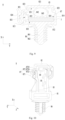
- the fixing member 8 further includes a mounting part 86 which is arranged on one side, facing away from the top cover 82, of the base 81, and connected to the base 81.
- the mounting part 86 is installed in the external pedestal and includes a clamping shaft 861 and a plurality of elastic cards 862 protruding from the outer peripheral surface thereof.
- the external pedestal is provided with a mounting hole fitting into the mounting part 86, through which the clamping shaft 861 of the mounting part 86 passes. When the clamping shaft 861 passes through the mounting hole, the elastic card 862 deforms under the action of the clamping shaft 861 and the wall of the mounting hole.
- the top cover 82 includes a body portion 821, an inner wall, facing the base 81, of the body portion 821 is configured to constitute at least part of the top wall 831, and the first elastic member 84 is arranged on the body portion 821 of the top cover 82.
- the inner wall, facing the base 81, of the body portion 821 may constitute part or all of the top wall 831.
- the first elastic member 84 is connected to the body portion 821 and protrudes from an inner wall thereof. When the bus component 7 passes through the accommodating groove 83, the first elastic member 84 abuts the bus component 7 against the bottom wall 832 of the accommodating groove 83.
- the body portion 821 is generally flat.
- the top cover 82 includes a body portion 821, and at least two bent portions 822 connected to both ends of the body portion 821 respectively in the second direction Y, and each of the bent portions 822 is bent towards one side close to the base 81 with respect to the body portion 821.
- the second through holes 823 of the two bent portions 822 allow an external strap to pass through.
- a bus component is arranged on one side, facing away from the base 81, of the body portion 821 (hereinafter referred to as an upper bus component)
- a strap may be used to pass through the second through holes 823 of the two bent portions 822 and surround the body portion 821 and the upper bus component to fix the upper bus component and the top cover 82 together.
- the first elastic member 84 is provided with a third through hole 841, and the projection of the second through hole 823 in the second direction Y at least partially overlaps with the projection of the third through hole 841 in the second direction Y.
- the first elastic member 84 includes a first elastic portion 842 connected to the body portion 821 of the top cover 82, and a first abutting portion 843 connected to one end, facing away from the body portion 821, of the first elastic portion 842.
- the first abutting portion 843 and the bottom wall 832 are arranged at intervals, and the first abutting portion 843 is configured to abut against the bus component 7 to fix the bus component 7 between the first abutting portion 843 and the bottom wall 832.
- the first elastic portion 842 is an elastically deformable part of the first elastic member 84.
- the first elastic portion 842 is elastically deformed to produce an elastic force, which acts on the bus component 7 through the first abutting portion 843.
- the first abutting portion 843 and the top wall 831 are arranged at intervals, and the first elastic portion 842 is arranged between the first abutting portion 843 and the top wall 831.
- the distance between the first abutting portion 843 and the top wall 831 and the distance between the first abutting portion 843 and the bottom wall 832 may be changed by changing the deformation amount of the first elastic portion 842.
- At least part of the first elastic portion 842 is arc-shaped.
- the arc-shaped structure has good elasticity, which is helpful to improving the elastic deformation ability of the first elastic portion 842.
- the first elastic member 84 includes at least two first elastic portions 842 arranged at intervals in the second direction Y. In the first direction X, the two first elastic portions 842 are located between the first abutting portion 843 and the body portion 821, and may improve the stress uniformity of the first abutting portion 843 and enhance the stability of the bus component 7.
- the first elastic portion 842 includes a first base portion 842a connected to a surface, facing the body portion 821, of the first abutting portion 843, and having two first surfaces 8421 arranged opposite to each other in the thickness direction thereof; a first supporting portion 842b connecting the body portion 821 and one end, facing away from the first abutting portion 843 of the first base portion 842a; a first protrusion portion 842c protruding from the first surface 8421 of the first base portion 842a; and a second supporting portion 842d connecting the first protrusion portion 842c and the body portion 821, characterized in that the first supporting portion 842b and the second supporting portion 842d are arranged at intervals in a third direction Z which intersects with both the first direction X and the second direction Y.
- the first supporting portion 842b and the second supporting portion 842d are arranged at intervals in the third direction Z, arranged therebetween a third through hole 841 which may reduce the strength of the first supporting portion 842b and the second supporting portion 842d, and improve the elasticity of the first supporting portion 842b and the second supporting portion 842d.
- the third through hole 841 may also provide an avoidance space for the strap to avoid the first elastic member 84 interfering with the strap.
- the first supporting portion 842b is connected to an end face, facing away from the first abutting portion 843, of the first base portion 842a, and the end face of the first base portion 842a is connected to the two first surfaces 8421.
- the first protrusion portion 842c is provided to allow the second supporting portion 842d to avoid the end face of the first base portion 842a, and the first supporting portion 842b and the second supporting portion 842d are arranged in a staggered manner.
- the first supporting portion 842b and the second supporting portion 842d may be punched. Since the first supporting portion 842b and the second supporting portion 842d are arranged in a staggered manner and do not overlap in the third direction Z, the first supporting portion 842b and the second supporting portion 842d may be formed after punched twice in the third direction Z.
- the first protrusion portion 842c protrudes from a first surface 8421 inside the first base portion 842a.
- the third direction Z is perpendicular to the first direction X and the second direction Y.
- a groove 811 is formed on the base 81 and constitutes at least part of the accommodating groove 83.
- the groove 811 of the base 81 may constitute part or all of the accommodating groove 83.
- the groove 811 is provided with an opening in one end in the first direction X, which is covered by the top cover 82.
- the bus component 7 and the fixing member 8 may be assembled according to the following steps: opening the top cover 82 to detach the top cover 82 from the first limiting part 813, and rotating the top cover 82 around the connecting member 87; placing the bus component 7 in the groove 811 of the base 81; and rotating the top cover 82 to clamp the top cover 82 to the first limiting part 813.
- the thickness of at least part of the connecting member 87 is smaller than that of the second limiting part 814.
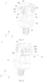
- Fig. 8 is an enlarged view of the fixing member at the round frame B in Fig. 4 .
- the first limiting part 813 includes a limiting plate 8131, and a clamping seat 8132 connected to the limiting plate 8131 and located at one side, away from the second limiting part 814, of the limiting plate 8131, and a clamping slot 8133 is formed between the limiting plate 8131 and the clamping seat 8132.
- the top cover 82 includes a buckling portion 824 used for being inserted into the clamping slot 8133 and clamped on the clamping seat 8132.
- An inner wall, facing the second limiting part 814, of the first limiting plate 8131 may be used as the first inner side wall 833 of the accommodating groove 83.
- the buckling portion 824 may be directly connected to the body portion 821, or indirectly connected to the body portion 821, for example, through the bent portion 822.
- the buckling portion 824 includes a first clamping portion 8241 and a second clamping portion 8242, which are arranged in a third direction Z intersecting with both the first direction X and the second direction Y.
- the clamping seat 8132 includes a third clamping portion 813a and a fourth clamping portion 813b arranged in the third direction Z.
- the first clamping portion 8241 is located on one side, facing the bottom wall 832, of the third clamping portion 813a
- the second clamping portion 8242 is located on one side, facing the bottom wall 832, of the fourth clamping portion 813b when the buckling portion 824 is clamped to the clamping seat 8132.
- a clamping surface between the first clamping portion 8241 and the third clamping portion 813a and a clamping surface between the second clamping portion 8242 and the fourth clamping portion 813b are arranged in a staggered way in the first direction X and/or the second direction Y.
- the first clamping portion 8241 and the second clamping portion 8242 may be continuously arranged in the third direction Z, or arranged at intervals in the third direction Z; while the third clamping portion 813a and the fourth clamping portion 813b may be continuously arranged in the third direction Z, or arranged at intervals in the third direction Z.
- the clamping seat 8132 is configured to be elastic and deformable. When it is necessary to open the top cover 82, the clamping seat 8132 may be rotated to detach the third clamping portion 813a from the first clamping portion 8241, and to detach the fourth clamping portion 813b from the second clamping portion 8242.
- the clamping seat 8132 includes a bent portion 813c connected to the limiting plate 8131, and the first and second clamping portions 8241 and 8242 are connected to one end, away from the limiting plate 8131, of the bent portion 813c.
- the bent portion 813c is configured to be elastically deformable under stress.
- a clamping surface between the first clamping portion 8241 and the third clamping portion 813a and a clamping surface between the second clamping portion 8242 and the fourth clamping portion 813b are arranged in a staggered way in the first direction X and/or the second direction Y, so as to form a two-stage buckle structure which can improve the structural stability and reduce the risk of the buckling portion 824 falling out of the clamping slot 8133.
- the connecting member 87 includes a deformation portion 871 rotatably connected to the second limiting part 814, and a connecting portion 872 connected to the deformation portion 871 and the top cover 82 and provided with a backstop portion 8721.
- the base 81 is provided with a first convex rib 815 protruding from the second limiting part 814; when the top cover 82 is clamped to the first limiting part 813, the first convex rib 815 fits with the backstop portion 8721 to limit the movement of the connecting portion 872 in the first direction X away from the base 81.
- the first convex rib 815 can strengthen the local strength of the second limiting part 814.
- the top cover 82 pulls the deformation portion 871 and the connecting portion 872; and the first convex rib 815 may fit with the backstop portion 8721 to limit the movement of the connecting portion 872 in the first direction X away from the base 81, avoiding excessive deformation of the deformation portion 871.
- the second convex rib 816 can strengthen the local strength of the second limiting part 814.
- the top cover 82 pulls the deformation portion 871 and the connection part 872; and the second convex rib 816 may abut against the connecting portion 872 to limit the movement of the connecting portion 872 in a direction towards the second limiting part 814, avoiding excessive deformation of the deformation portion 871 under the action of the connecting portion 872.
- first convex rib 815 and the second convex rib 816 are integrally formed, and may be continuously arranged in the third direction Z.
- the first convex rib 815 and the second convex rib 816 are arranged in a staggered manner in the first direction X.
- the first convex rib 815 is located on one side, away from the deformation portion 871, of the stopper 8721 to limit the movement of the backstop portion 8721 in the first direction X
- the second convex rib 816 is located between the backstop portion 8721 and the second limiting part 814 to limit the movement of the backstop portion 8721 in the second direction Y.
- the connecting portion 872 is provided with a first through hole 8722
- the backstop portion 8721 is formed on one side, close to the deformation portion 871, of the first through hole 8722
- the first convex rib 815 is inserted into the first through hole 8722 to fix with the backstop portion 8721 when the top cover 82 is clamped to the first limiting part 813.
- the strength of the connecting portion 872 can be reduced by providing the first through hole 8722; in this way, the connecting portion 872 can be adaptively deformed in the opening or closing process of the top cover 82.
- the first through hole 8722 provides a space for the first convex rib 815, which is convenient to realize the fitting of the first convex rib 815 with the backstop portion 8721.
- the backstop portion 8721 is connected to an end, facing away from the second limiting part 814, of the deformation portion 871.
- the connecting portion 872 further includes a second protrusion portion 8723, a first extension portion 8724 and a second extension portion 8725.
- the second protrusion portion 8723 protrudes from a surface, facing the second limiting part 814, of the backstop portion 8721.
- the first extension portion 8724 is connected to the top cover 82 and one end, facing away from the deformation portion 871, of the backstop portion 8721.
- the second extension portion 8725 is connected to the second protrusion portion 8723 and the top cover 82.
- the first extension portion 8724 and the second extension portion 8725 are arranged at intervals in the third direction Z intersecting with both the first direction X and the second direction Y, and the first through hole 8722 is formed between the first extension portion 8724 and the second extension portion 8725.
- the first through hole 8722 may reduce the strength of the first extension portion 8724 and the second extension portion 8725, and improve the elasticity of the first extension portion 8724 and the second extension portion 8725.
- the first extension portion 8724 is connected to an end face, away from the deformation portion 871, of the backstop portion 8721.
- the second protrusion portion 8723 is provided so that the second extension portion 8725 may avoid the end face of the backstop portion 8721. In this way, the first extension portion 8724 and the second extension portion 8725 are arranged in a staggered way.
- the first extension portion 8724 and the second extension portion 8725 may be punched. Since the first extension portion 8724 and the second extension portion 8725 are arranged in a staggered manner and do not overlap in the third direction Z, the first extension portion 8724 and the second extension portion 8725 may be formed after punched twice in the third direction Z.
- Fig. 14 is a schematic flow chart of a method for manufacturing a battery provided in some embodiments of the application.
- the first elastic member is configured to abut against the bus component in a first direction to fix the bus component between the top wall and the bottom wall
- the second elastic member is configured to abut against the bus component in a second direction to fix the bus component between two inner side walls of the accommodating groove, the first direction intersects with the second direction.
- the batteries provided in the above embodiments can be made as a reference to the related structure of the battery manufactured by the above manufacturing method.
- step S100 and step S400 may be performed in no particular order, or at the same time.
- Fig. 15 is a schematic block diagram of a system for manufacturing a battery provided in some embodiments of the application.
- a system 9 for manufacturing a battery includes a first supply device 91, configured to provide an external pedestal; a second supply device 92, configured to provide a battery cell and install the battery cell in the external pedestal; a third supply device 93, configured to provide a bus component and electrically connecting the bus component to the battery cell; a fourth supply device 94, configured to provide a fixing member which includes a base, a top cover, a first elastic member and a second elastic member, characterized in that the base is connected to the top cover, an accommodating groove is formed between the base and the top cover, the first elastic member is provided between the top wall and the bottom wall of the accommodating groove, and the second elastic member is provided between the two inner walls of the accommodating groove; and an assembly device 95, connecting the base to the external pedestal, and accommodating part of the bus component in the accommodating groove, characterized in that the first elastic member is configured to abut against the bus component in a first direction to fix the bus component between the top wall and the bottom wall
- the batteries provided in the above embodiments can be made as a reference to the related structure of the battery manufactured by the above manufacturing method.
Landscapes
- Chemical & Material Sciences (AREA)
- Chemical Kinetics & Catalysis (AREA)
- Electrochemistry (AREA)
- General Chemical & Material Sciences (AREA)
- Engineering & Computer Science (AREA)
- Manufacturing & Machinery (AREA)
- Materials Engineering (AREA)
- Mechanical Engineering (AREA)
- Battery Mounting, Suspending (AREA)
- Installation Of Indoor Wiring (AREA)
- Connection Of Batteries Or Terminals (AREA)
Claims (13)
- Befestigungselement (8) zum Befestigen eines Werkstücks, aufweisend:eine Basis (81) zum Verbinden eines externen Sockels;eine obere Abdeckung (82), die mit der Basis (81) verbunden ist, eine Aufnahmenut (83) zum Aufnehmen des Werkstücks, die zwischen der Basis (81) und der oberen Abdeckung (82) ausgebildet ist;ein erstes elastisches Element (84), das zwischen der Oberwand (831) und der Bodenwand (832) der Aufnahmenut (83) angeordnet ist und dazu eingerichtet ist, in einer ersten Richtung an dem Werkstück anzuliegen, um das Werkstück zwischen der Oberwand (831) und der Bodenwand (832) zu befestigen; undein zweites elastisches Element (85), das zwischen zwei inneren Seitenwänden der Aufnahmenut (83) angeordnet ist und dazu eingerichtet ist, in einer zweiten Richtung an dem Werkstück anzuliegen, um das Werkstück zwischen den zwei inneren Seitenwänden der Aufnahmenut (83) zu befestigen, wobei die erste Richtung die zweite Richtung kreuzt;wobei die obere Abdeckung (82) einen Körperabschnitt (821) aufweist, eine der Basis (81) zugewandte Innenwand des Körperabschnitts (821) dazu eingerichtet ist, zumindest einen Teil der Oberwand (831) zu bilden, und das erste elastische Element (84) auf dem Körperabschnitt (821) der oberen Abdeckung (82) angeordnet ist,wobei das erste elastische Element (84) aufweist:einen ersten elastischen Abschnitt (842), der mit dem Körperabschnitt (821) der oberen Abdeckung (82) verbunden ist; undeinen ersten Anliegeabschnitt (843), der mit einem dem Körperabschnitt (821) abgewandten Ende des ersten elastischen Abschnitts (842) verbunden ist;wobei in der ersten Richtung der erste Anliegeabschnitt (843) und die Bodenwand (832) in Abständen angeordnet sind und der erste Anliegeabschnitt (843) dazu eingerichtet ist, an dem Werkstück anzuliegen, um das Werkstück zwischen dem ersten Anliegeabschnitt (843) und der Bodenwand (832) zu befestigen;dadurch gekennzeichnet, dass der erste elastische Abschnitt (842) aufweist:einen ersten Basisabschnitt (842a), der mit einer dem Körperabschnitt (821) zugewandten Oberfläche des ersten Anliegeabschnitts (843) verbunden ist und zwei erste Oberflächen (8421) aufweist, die in der Dickenrichtung davon einander gegenüber angeordnet sind;einen ersten Stützabschnitt (842b), der den Körperabschnitt (821) und ein dem ersten Anliegeabschnitt (843) abgewandtes Ende des ersten Basisabschnitts (842a) verbindet;einen ersten Vorsprungabschnitt (842c), der von der ersten Oberfläche (8421) des ersten Basisabschnitts (842a) hervorsteht; undeinen zweiten Stützabschnitt (842d), der den ersten Vorsprungabschnitt (842c) und den Körperabschnitt (821) verbindet, wobei der erste Stützabschnitt (842b) und der zweite Stützabschnitt (842d) in einer dritten Richtung, die sowohl die erste Richtung als auch die zweite Richtung kreuzt, in Abständen angeordnet sind.
- Befestigungselement (8) nach Anspruch 1, dadurch gekennzeichnet, dass zumindest ein Teil des ersten elastischen Abschnitts (842) bogenförmig ist.
- Befestigungselement (8) nach einem der Ansprüche 1 bis 2, dadurch gekennzeichnet, dassdie zwei inneren Seitenwände der Aufnahmenut (83) eine erste innere Seitenwand (833) und eine zweite innere Seitenwand (834) sind, die in der zweiten Richtung einander gegenüber angeordnet sind; unddas zweite elastische Element (85) aufweist:einen zweiten elastischen Abschnitt (851), der mit einem Ende mit der ersten inneren Seitenwand (833) verbunden ist;einen zweiten Anliegeabschnitt (852), der mit dem anderen, der ersten inneren Seitenwand (833) abgewandten Ende des zweiten elastischen Abschnitts (851) verbunden ist;wobei in der zweiten Richtung der zweite Anliegeabschnitt (852) und die zweite innere Seitenwand (834) in Abständen angeordnet sind und der zweite Anliegeabschnitt (852) dazu eingerichtet ist, an dem Werkstück anzuliegen, um das Werkstück zwischen dem zweiten Anliegeabschnitt (852) und der zweiten inneren Seitenwand (834) zu befestigen.
- Befestigungselement (8) nach einem der Ansprüche 1 bis 3, dadurch gekennzeichnet, dass eine Nut (811) auf der Basis (81) ausgebildet ist und zumindest einen Teil der Aufnahmenut (83) bildet.
- Befestigungselement (8) nach Anspruch 4, dadurch gekennzeichnet, dassdie Basis (81) eine Bodenplatte (812) sowie ein damit verbundenes erstes Begrenzungsteil (813) und zweites Begrenzungsteil (814) aufweist, wobei das erste Begrenzungsteil (813) und das zweite Begrenzungsteil (814) in der zweiten Richtung in Abständen angeordnet sind und die Bodenplatte (812), das erste Begrenzungsteil (813) und das zweite Begrenzungsteil (814) die Nut (811) bilden; undein Ende der oberen Abdeckung (82) an das erste Begrenzungsteil (813) geklemmt ist und/oder das andere Ende davon an das zweite Begrenzungsteil (814) geklemmt ist, insbesondere wobeiein Ende der oberen Abdeckung (82) an das erste Begrenzungsteil (813) geklemmt ist und das andere Ende davon durch ein Verbindungselement (87) drehbar mit dem zweiten Begrenzungsteil (814) verbunden ist.
- Befestigungselement (8) nach Anspruch 5, dadurch gekennzeichnet, dassdas Verbindungselement (87) einen Verformungsabschnitt (871), der drehbar mit dem zweiten Begrenzungsteil (814) verbunden ist, und einen Verbindungsabschnitt (872) aufweist, der mit dem Verformungsabschnitt (871) und der oberen Abdeckung (82) verbunden ist und mit einem Anschlagabschnitt (8721) versehen ist; unddie Basis (81) mit einer ersten konvexen Rippe (815) versehen ist, die aus dem zweiten Begrenzungsteil (814) hervorsteht; wobei die erste konvexe Rippe (815), wenn die obere Abdeckung (82) an das erste Begrenzungsteil (813) geklemmt ist, mit dem Anschlagabschnitt (8721) zusammenpasst, um die Bewegung des Verbindungsabschnitts (872) in der ersten Richtung fort von der Basis (81) zu begrenzen.
- Befestigungselement (8) nach Anspruch 6, dadurch gekennzeichnet, dass die Basis ferner mit einer zweiten konvexen Rippe (816) versehen ist, die von dem zweiten Begrenzungsteil (814) hervorsteht, und die zweite konvexe Rippe (816) mit dem Verbindungsabschnitt (872) zusammenpasst, um die Bewegung des Verbindungsabschnitts (872) in eine Richtung zu dem zweiten Begrenzungsteil (814) hin zu begrenzen, insbesondere wobei die erste konvexe Rippe (815) und die zweite konvexe Rippe (816) einstückig ausgebildet sind.
- Befestigungselement (8) nach einem der Ansprüche 6 und 7, dadurch gekennzeichnet, dass der Verbindungsabschnitt (872) mit einem ersten Durchgangsloch (8722) versehen ist, der Anschlagabschnitt (8721) auf einer dem Verformungsabschnitt (871) nahen Seite des ersten Durchgangslochs (8722) ausgebildet ist und die erste konvexe Rippe (815) in das erste Durchgangsloch (8722) eingeführt ist, um mit dem Anschlagabschnitt (8721) befestigt zu sein, wenn die obere Abdeckung (82) an das erste Begrenzungsteil (813) geklemmt ist, insbesondere wobei der Anschlagabschnitt (8721) mit einem dem zweiten Begrenzungsteil (814) abgewandten Ende des Verformungsabschnitts (871) verbunden ist;
wobei der Verbindungsabschnitt (872) ferner aufweist:einen zweiten Vorsprungabschnitt (8723), der von der dem zweiten Begrenzungsteil (814) zugewandten Oberfläche des Anschlagabschnitts (8721) hervorsteht;einen ersten Erweiterungsabschnitt (8724), der die obere Abdeckung (82) und ein dem Verformungsabschnitt (871) abgewandtes Ende des Anschlagabschnitts (8721) verbindet; undeinen zweiten Erweiterungsabschnitt (8725), der den zweiten Vorsprungabschnitt (8723) und die obere Abdeckung (82) verbindet, wobei der erste Erweiterungsabschnitt (8724) und der zweite Erweiterungsabschnitt (8725) in einer dritten Richtung, die sowohl die erste Richtung als auch die zweite Richtung kreuzt, in Abständen angeordnet sind und das erste Durchgangsloch (8722) zwischen dem ersten Erweiterungsabschnitt (8724) und dem zweiten Erweiterungsabschnitt (8725) ausgebildet ist. - Befestigungselement nach einem der Ansprüche 5 bis 8, wobei das erste Begrenzungsteil eine Begrenzungsplatte und einen Klemmsitz aufweist, der mit der Begrenzungsplatte verbunden ist und sich auf einer Seite der Begrenzungsplatte fort von dem zweiten Begrenzungsteil befindet, und zwischen der Begrenzungsplatte und dem Klemmsitz ein Klemmschlitz ausgebildet ist;die obere Abdeckung einen Schnallenabschnitt aufweist, der dazu verwendet wird, in den Klemmschlitz eingeführt und an den Klemmsitz geklemmt zu werden, insbesondere wobeider Schnallenabschnitt einen ersten Klemmabschnitt und einen zweiten Klemmabschnitt aufweist, die beide in einer dritten Richtung angeordnet sind, die sowohl die erste Richtung als auch die zweite Richtung kreuzt;der Klemmsitz einen dritten Klemmabschnitt und einen vierten Klemmabschnitt aufweist, die in der dritten Richtung angeordnet sind;wenn die Schnalle an den Klemmsitz geklemmt ist, sich der erste Klemmabschnitt auf einer der Bodenwand zugewandten Seite des dritten Klemmabschnitts befindet und sich der zweite Klemmabschnitt auf einer der Bodenwand zugewandten Seite des vierten Klemmabschnitts befindet; undeine Klemmfläche zwischen dem ersten Klemmabschnitt und dem dritten Klemmabschnitt und eine Klemmfläche zwischen dem zweiten Klemmabschnitt und dem vierten Klemmabschnitt in der ersten Richtung und/oder der zweiten Richtung zueinander versetzt angeordnet sind.
- Befestigungselement nach einem der Ansprüche 1 bis 9, wobei die obere Abdeckung einen Körperabschnitt und mindestens zwei gebogene Abschnitte aufweist, die jeweils mit einem der beiden Enden des Körperabschnitts in der zweiten Richtung verbunden sind, und jeder gebogene Abschnitt in Bezug auf den Körperabschnitt in Richtung einer Seite nahe der Basis gebogen ist; und
die zwei gebogenen Abschnitte mit zweiten Durchgangslöchern versehen sind, die in der zweiten Richtung ausgerichtet sind, insbesondere wobei das erste elastische Element mit einem dritten Durchgangsloch versehen ist und die Projektion des zweiten Durchgangslochs in die zweite Richtung zumindest teilweise die Projektion des dritten Durchgangslochs in die zweite Richtung überlappt. - Befestigungselement nach einem der Ansprüche 1 bis 10, ferner aufweisend ein Montageteil, das auf einer der oberen Abdeckung abgewandten Seite der Basis angeordnet ist und mit der Basis verbunden ist;
wobei das Montageteil in dem externen Sockel installiert ist und eine Klemmwelle und mehrere elastische Karten aufweist, die von einer Außenumfangsfläche davon hervorstehen, insbesondere wobei das Werkstück eine Buskomponente einer Batterie aufweist. - Batterie, welche aufweist:eine Batteriezelle;eine Buskomponente, die elektrisch mit der Batteriezelle verbunden ist; unddas Befestigungselement nach einem der Ansprüche 1 bis 11, wobei die Buskomponente dazu eingerichtet ist, die Aufnahmenut zu durchlaufen.
- Verfahren zum Herstellen einer Batterie nach Anspruch 12, umfassend:Bereitstellen eines externen Sockels;Bereitstellen einer Batteriezelle und Installieren der Batteriezelle in den externen Sockel;Bereitstellen einer Buskomponente und elektrisches Verbinden der Buskomponente mit der Batteriezelle;Bereitstellen eines Befestigungselements, das eine Basis, eine obere Abdeckung, ein erstes elastisches Element und ein zweites elastisches Element aufweist, wobei die Basis mit der oberen Abdeckung verbunden ist, eine Aufnahmenut zwischen der Basis und der oberen Abdeckung ausgebildet ist, das erste elastische Element zwischen der Oberwand und der Bodenwand der Aufnahmenut bereitgestellt ist und das zweite elastische Element zwischen den zwei Innenwänden der Aufnahmenut bereitgestellt ist; undVerbinden der Basis mit dem externen Sockel und Aufnehmen eines Teils der Buskomponente in die Aufnahmenut,wobei das erste elastische Element dazu eingerichtet ist, in einer ersten Richtung an der Buskomponente anzuliegen, um die Buskomponente zwischen der Oberwand und der Bodenwand zu befestigen, und das zweite elastische Element dazu eingerichtet ist, in einer zweiten Richtung an der Buskomponente anzuliegen, um die Buskomponente zwischen zwei inneren Seitenwänden der Aufnahmenut zu befestigen, wobei die erste Richtung die zweite Richtung kreuzt.
Priority Applications (1)
| Application Number | Priority Date | Filing Date | Title |
|---|---|---|---|
| HUE21908115A HUE072625T2 (hu) | 2021-05-26 | 2021-05-26 | Rögzítõelem, akkumulátor és eljárás akkumulátor elõállítására |
Applications Claiming Priority (1)
| Application Number | Priority Date | Filing Date | Title |
|---|---|---|---|
| PCT/CN2021/096020 WO2022246685A1 (zh) | 2021-05-26 | 2021-05-26 | 固定构件、电池、用电装置及电池的制造方法和制造系统 |
Publications (3)
| Publication Number | Publication Date |
|---|---|
| EP4123817A1 EP4123817A1 (de) | 2023-01-25 |
| EP4123817A4 EP4123817A4 (de) | 2023-07-19 |
| EP4123817B1 true EP4123817B1 (de) | 2025-07-02 |
Family
ID=84193380
Family Applications (1)
| Application Number | Title | Priority Date | Filing Date |
|---|---|---|---|
| EP21908115.5A Active EP4123817B1 (de) | 2021-05-26 | 2021-05-26 | Befestigungselement, batterie sowie verfahren zur herstellung einer batterie |
Country Status (8)
| Country | Link |
|---|---|
| US (1) | US20220384913A1 (de) |
| EP (1) | EP4123817B1 (de) |
| JP (1) | JP7532547B2 (de) |
| KR (1) | KR102770327B1 (de) |
| CN (1) | CN115715443B (de) |
| ES (1) | ES3041468T3 (de) |
| HU (1) | HUE072625T2 (de) |
| WO (1) | WO2022246685A1 (de) |
Families Citing this family (1)
| Publication number | Priority date | Publication date | Assignee | Title |
|---|---|---|---|---|
| CN222924711U (zh) * | 2024-08-20 | 2025-05-30 | 惠州亿纬锂能股份有限公司 | 汇流排固定结构及电池包 |
Citations (2)
| Publication number | Priority date | Publication date | Assignee | Title |
|---|---|---|---|---|
| JP2005160273A (ja) * | 2003-11-28 | 2005-06-16 | Nissan Motor Co Ltd | バスバー固定器 |
| WO2010001477A1 (ja) * | 2008-07-04 | 2010-01-07 | 星和電機株式会社 | 電線保持具 |
Family Cites Families (22)
| Publication number | Priority date | Publication date | Assignee | Title |
|---|---|---|---|---|
| JPS513525B1 (de) * | 1970-12-17 | 1976-02-04 | ||
| DE60237643D1 (de) * | 2001-12-03 | 2010-10-21 | Japan Techno Co Ltd | Wasserstoff-sauerstoff-gasgenerator und verfahren zur erzeugung von wasserstoff-sauerstoff-gas mit dem generator |
| JP2004140921A (ja) * | 2002-10-17 | 2004-05-13 | Furukawa Electric Co Ltd:The | フラットケーブルの接続構造 |
| DE10313411B3 (de) * | 2003-03-25 | 2004-08-26 | Newfrey Llc, Newark | Halter, insbesondere für Rohre, Kabel oder dergleichen |
| EP2071647B1 (de) * | 2004-10-08 | 2018-01-17 | Honda Motor Co., Ltd. | Verriegelungsstruktur einer Box für elektrische Komponenten |
| JP5612904B2 (ja) * | 2010-05-13 | 2014-10-22 | 矢崎総業株式会社 | カバー部材及び該カバー部材を備えた電源装置 |
| JP5644523B2 (ja) * | 2010-12-07 | 2014-12-24 | 住友電装株式会社 | バッテリ接続具 |
| JP2012164477A (ja) * | 2011-02-04 | 2012-08-30 | Sumitomo Wiring Syst Ltd | バッテリ接続具 |
| JP5787140B2 (ja) * | 2011-06-13 | 2015-09-30 | 株式会社オートネットワーク技術研究所 | 電池配線モジュール |
| JP5939421B2 (ja) * | 2011-07-07 | 2016-06-22 | 株式会社オートネットワーク技術研究所 | 電池配線モジュール |
| JP6145314B2 (ja) * | 2013-05-29 | 2017-06-07 | 矢崎総業株式会社 | バスバモジュール及び電源装置 |
| DE102013017249B4 (de) * | 2013-10-17 | 2021-09-09 | Kostal Kontakt Systeme Gmbh | Steckverbinderanordnung zur elektrischen Kopplung von Batteriemodulen und Batteriemodulanordnung |
| CN104752650B (zh) * | 2013-12-31 | 2017-05-03 | 比亚迪股份有限公司 | 动力电池模组 |
| JP6780288B2 (ja) * | 2016-05-09 | 2020-11-04 | 株式会社オートネットワーク技術研究所 | 接続モジュール |
| JP6693334B2 (ja) * | 2016-08-23 | 2020-05-13 | 株式会社豊田自動織機 | 電池モジュール |
| JP6574796B2 (ja) * | 2017-01-31 | 2019-09-11 | 矢崎総業株式会社 | バスバー保持構造 |
| FR3062956B1 (fr) * | 2017-02-15 | 2021-07-23 | Delphi Int Operations Luxembourg Sarl | Ensemble de connexion electrique femelle |
| CN207800665U (zh) * | 2018-02-01 | 2018-08-31 | 宁德时代新能源科技股份有限公司 | 二次电池的顶盖组件以及二次电池 |
| CN210092200U (zh) * | 2019-03-28 | 2020-02-18 | 泰科电子日本合同会社 | 用于电池模组的连接组件及电池模组 |
| JP7034559B2 (ja) * | 2019-07-05 | 2022-03-14 | 矢崎総業株式会社 | 配索材固定体 |
| CN112768845B (zh) * | 2021-04-09 | 2021-09-14 | 江苏时代新能源科技有限公司 | 电池单体及其制造方法和制造系统、电池以及用电装置 |
| CN112820987B (zh) * | 2021-04-16 | 2021-07-09 | 江苏时代新能源科技有限公司 | 电池单体及其制造方法和制造系统、电池以及用电装置 |
-
2021
- 2021-05-26 ES ES21908115T patent/ES3041468T3/es active Active
- 2021-05-26 CN CN202180007080.1A patent/CN115715443B/zh active Active
- 2021-05-26 WO PCT/CN2021/096020 patent/WO2022246685A1/zh not_active Ceased
- 2021-05-26 HU HUE21908115A patent/HUE072625T2/hu unknown
- 2021-05-26 KR KR1020227038691A patent/KR102770327B1/ko active Active
- 2021-05-26 EP EP21908115.5A patent/EP4123817B1/de active Active
- 2021-05-26 JP JP2022565932A patent/JP7532547B2/ja active Active
-
2022
- 2022-06-23 US US17/847,182 patent/US20220384913A1/en active Pending
Patent Citations (2)
| Publication number | Priority date | Publication date | Assignee | Title |
|---|---|---|---|---|
| JP2005160273A (ja) * | 2003-11-28 | 2005-06-16 | Nissan Motor Co Ltd | バスバー固定器 |
| WO2010001477A1 (ja) * | 2008-07-04 | 2010-01-07 | 星和電機株式会社 | 電線保持具 |
Also Published As
| Publication number | Publication date |
|---|---|
| CN115715443B (zh) | 2024-09-06 |
| JP7532547B2 (ja) | 2024-08-13 |
| KR102770327B1 (ko) | 2025-02-20 |
| US20220384913A1 (en) | 2022-12-01 |
| EP4123817A1 (de) | 2023-01-25 |
| ES3041468T3 (en) | 2025-11-12 |
| JP2023531135A (ja) | 2023-07-21 |
| KR20220161480A (ko) | 2022-12-06 |
| EP4123817A4 (de) | 2023-07-19 |
| HUE072625T2 (hu) | 2025-11-28 |
| CN115715443A (zh) | 2023-02-24 |
| WO2022246685A1 (zh) | 2022-12-01 |
Similar Documents
| Publication | Publication Date | Title |
|---|---|---|
| CN116762202B (zh) | 电池单体及其制造方法和制造系统、电池以及用电装置 | |
| EP4148872B1 (de) | Batterie, strom verbrauchendes gerät, verfahren zur herstellung einer batterie und system zur herstellung einer batterie | |
| US20240283059A1 (en) | Battery cell, method and system for manufacturing battery cell, battery, and electrical device | |
| EP4528864A1 (de) | Batteriezelle, batterie und elektrische vorrichtung | |
| US12142747B2 (en) | Heat-exchanging component, method for manufacturing heat-exchanging component, system of manufacturing heat-exchanging component, battery and electricity-consuming apparatus | |
| US20240322375A1 (en) | Battery cell, method and apparatus for manufacturing same, battery, and power consuming device | |
| US20250329884A1 (en) | Battery cell, battery, and electrical device | |
| WO2025161358A1 (zh) | 电池及用电装置 | |
| EP4270609A1 (de) | Batterie und herstellungsverfahren und herstellungssystem dafür sowie elektrische ausrüstung | |
| CN219017845U (zh) | 电池及用电装置 | |
| EP4123817B1 (de) | Befestigungselement, batterie sowie verfahren zur herstellung einer batterie | |
| US20240234988A1 (en) | Battery cell and manufacturing method and manufacturing system therefor, battery and electrical device | |
| US20240347824A1 (en) | End cover assembly, battery cell, battery, and electrical device | |
| KR20230047466A (ko) | 배터리, 전기 장치, 배터리의 제조 방법 및 제조 설비 | |
| CN218939912U (zh) | 极耳支架、电池及用电装置 | |
| EP4507083A1 (de) | Batteriezelle und herstellungsverfahren dafür sowie batterie und elektrische vorrichtung | |
| EP4354556B1 (de) | Stromsammelkomponente, batteriezelle, batterie, herstellungsverfahren und vorrichtung für die stromsammelkomponente | |
| EP4528879A1 (de) | Batteriezelle, batterie und elektrische vorrichtung | |
| CN220527056U (zh) | 箱体组件、电池以及用电装置 | |
| US20250087789A1 (en) | Battery cell, battery, and electric apparatus | |
| US20240145876A1 (en) | Battery cell, manufacturing method and manufacturing device thereof, battery, and electric apparatus | |
| EP4583270A1 (de) | Batteriemodul, batterie, energiespeichervorrichtung und elektrische vorrichtung | |
| CN223123927U (zh) | 电池单体、电池装置和用电装置 | |
| EP4546556A1 (de) | Batteriezelle, batterie und elektrische vorrichtung | |
| CN116632318A (zh) | 电池单体及其制造方法和制造系统、电池以及用电装置 |
Legal Events
| Date | Code | Title | Description |
|---|---|---|---|
| STAA | Information on the status of an ep patent application or granted ep patent |
Free format text: STATUS: UNKNOWN |
|
| STAA | Information on the status of an ep patent application or granted ep patent |
Free format text: STATUS: THE INTERNATIONAL PUBLICATION HAS BEEN MADE |
|
| PUAI | Public reference made under article 153(3) epc to a published international application that has entered the european phase |
Free format text: ORIGINAL CODE: 0009012 |
|
| STAA | Information on the status of an ep patent application or granted ep patent |
Free format text: STATUS: REQUEST FOR EXAMINATION WAS MADE |
|
| 17P | Request for examination filed |
Effective date: 20220701 |
|
| AK | Designated contracting states |
Kind code of ref document: A1 Designated state(s): AL AT BE BG CH CY CZ DE DK EE ES FI FR GB GR HR HU IE IS IT LI LT LU LV MC MK MT NL NO PL PT RO RS SE SI SK SM TR |
|
| A4 | Supplementary search report drawn up and despatched |
Effective date: 20230619 |
|
| RIC1 | Information provided on ipc code assigned before grant |
Ipc: H01R 4/48 20060101ALI20230613BHEP Ipc: H01R 13/02 20060101ALI20230613BHEP Ipc: H01M 50/50 20210101AFI20230613BHEP |
|
| STAA | Information on the status of an ep patent application or granted ep patent |
Free format text: STATUS: EXAMINATION IS IN PROGRESS |
|
| 17Q | First examination report despatched |
Effective date: 20240228 |
|
| DAV | Request for validation of the european patent (deleted) | ||
| DAX | Request for extension of the european patent (deleted) | ||
| RAP1 | Party data changed (applicant data changed or rights of an application transferred) |
Owner name: CONTEMPORARY AMPEREX TECHNOLOGY(HONG KONG) LIMITED |
|
| GRAP | Despatch of communication of intention to grant a patent |
Free format text: ORIGINAL CODE: EPIDOSNIGR1 |
|
| STAA | Information on the status of an ep patent application or granted ep patent |
Free format text: STATUS: GRANT OF PATENT IS INTENDED |
|
| INTG | Intention to grant announced |
Effective date: 20250311 |
|
| GRAS | Grant fee paid |
Free format text: ORIGINAL CODE: EPIDOSNIGR3 |
|
| GRAA | (expected) grant |
Free format text: ORIGINAL CODE: 0009210 |
|
| STAA | Information on the status of an ep patent application or granted ep patent |
Free format text: STATUS: THE PATENT HAS BEEN GRANTED |
|
| AK | Designated contracting states |
Kind code of ref document: B1 Designated state(s): AL AT BE BG CH CY CZ DE DK EE ES FI FR GB GR HR HU IE IS IT LI LT LU LV MC MK MT NL NO PL PT RO RS SE SI SK SM TR |
|
| REG | Reference to a national code |
Ref country code: GB Ref legal event code: FG4D |
|
| REG | Reference to a national code |
Ref country code: CH Ref legal event code: EP |
|
| REG | Reference to a national code |
Ref country code: DE Ref legal event code: R096 Ref document number: 602021033593 Country of ref document: DE |
|
| P01 | Opt-out of the competence of the unified patent court (upc) registered |
Free format text: CASE NUMBER: APP_28842/2025 Effective date: 20250617 |
|
| REG | Reference to a national code |
Ref country code: IE Ref legal event code: FG4D |
|
| REG | Reference to a national code |
Ref country code: NL Ref legal event code: MP Effective date: 20250702 |
|
| REG | Reference to a national code |
Ref country code: ES Ref legal event code: FG2A Ref document number: 3041468 Country of ref document: ES Kind code of ref document: T3 Effective date: 20251112 |
|
| REG | Reference to a national code |
Ref country code: HU Ref legal event code: AG4A Ref document number: E072625 Country of ref document: HU |
|
| PG25 | Lapsed in a contracting state [announced via postgrant information from national office to epo] |
Ref country code: PT Free format text: LAPSE BECAUSE OF FAILURE TO SUBMIT A TRANSLATION OF THE DESCRIPTION OR TO PAY THE FEE WITHIN THE PRESCRIBED TIME-LIMIT Effective date: 20251103 |
|
| PG25 | Lapsed in a contracting state [announced via postgrant information from national office to epo] |
Ref country code: NL Free format text: LAPSE BECAUSE OF FAILURE TO SUBMIT A TRANSLATION OF THE DESCRIPTION OR TO PAY THE FEE WITHIN THE PRESCRIBED TIME-LIMIT Effective date: 20250702 |
|
| REG | Reference to a national code |
Ref country code: AT Ref legal event code: MK05 Ref document number: 1810345 Country of ref document: AT Kind code of ref document: T Effective date: 20250702 |
|
| PG25 | Lapsed in a contracting state [announced via postgrant information from national office to epo] |
Ref country code: IS Free format text: LAPSE BECAUSE OF FAILURE TO SUBMIT A TRANSLATION OF THE DESCRIPTION OR TO PAY THE FEE WITHIN THE PRESCRIBED TIME-LIMIT Effective date: 20251102 |
|
| PG25 | Lapsed in a contracting state [announced via postgrant information from national office to epo] |
Ref country code: NO Free format text: LAPSE BECAUSE OF FAILURE TO SUBMIT A TRANSLATION OF THE DESCRIPTION OR TO PAY THE FEE WITHIN THE PRESCRIBED TIME-LIMIT Effective date: 20251002 |
|
| REG | Reference to a national code |
Ref country code: LT Ref legal event code: MG9D |
|
| PG25 | Lapsed in a contracting state [announced via postgrant information from national office to epo] |
Ref country code: AT Free format text: LAPSE BECAUSE OF FAILURE TO SUBMIT A TRANSLATION OF THE DESCRIPTION OR TO PAY THE FEE WITHIN THE PRESCRIBED TIME-LIMIT Effective date: 20250702 |
|
| PG25 | Lapsed in a contracting state [announced via postgrant information from national office to epo] |
Ref country code: FI Free format text: LAPSE BECAUSE OF FAILURE TO SUBMIT A TRANSLATION OF THE DESCRIPTION OR TO PAY THE FEE WITHIN THE PRESCRIBED TIME-LIMIT Effective date: 20250702 |
|
| PG25 | Lapsed in a contracting state [announced via postgrant information from national office to epo] |
Ref country code: HR Free format text: LAPSE BECAUSE OF FAILURE TO SUBMIT A TRANSLATION OF THE DESCRIPTION OR TO PAY THE FEE WITHIN THE PRESCRIBED TIME-LIMIT Effective date: 20250702 |
|
| PG25 | Lapsed in a contracting state [announced via postgrant information from national office to epo] |
Ref country code: GR Free format text: LAPSE BECAUSE OF FAILURE TO SUBMIT A TRANSLATION OF THE DESCRIPTION OR TO PAY THE FEE WITHIN THE PRESCRIBED TIME-LIMIT Effective date: 20251003 |
|
| PG25 | Lapsed in a contracting state [announced via postgrant information from national office to epo] |
Ref country code: CZ Free format text: LAPSE BECAUSE OF FAILURE TO SUBMIT A TRANSLATION OF THE DESCRIPTION OR TO PAY THE FEE WITHIN THE PRESCRIBED TIME-LIMIT Effective date: 20250702 Ref country code: SE Free format text: LAPSE BECAUSE OF FAILURE TO SUBMIT A TRANSLATION OF THE DESCRIPTION OR TO PAY THE FEE WITHIN THE PRESCRIBED TIME-LIMIT Effective date: 20250702 |
|
| PG25 | Lapsed in a contracting state [announced via postgrant information from national office to epo] |
Ref country code: LV Free format text: LAPSE BECAUSE OF FAILURE TO SUBMIT A TRANSLATION OF THE DESCRIPTION OR TO PAY THE FEE WITHIN THE PRESCRIBED TIME-LIMIT Effective date: 20250702 |
|
| PG25 | Lapsed in a contracting state [announced via postgrant information from national office to epo] |
Ref country code: BG Free format text: LAPSE BECAUSE OF FAILURE TO SUBMIT A TRANSLATION OF THE DESCRIPTION OR TO PAY THE FEE WITHIN THE PRESCRIBED TIME-LIMIT Effective date: 20250702 Ref country code: PL Free format text: LAPSE BECAUSE OF FAILURE TO SUBMIT A TRANSLATION OF THE DESCRIPTION OR TO PAY THE FEE WITHIN THE PRESCRIBED TIME-LIMIT Effective date: 20250702 |
|
| PG25 | Lapsed in a contracting state [announced via postgrant information from national office to epo] |
Ref country code: RS Free format text: LAPSE BECAUSE OF FAILURE TO SUBMIT A TRANSLATION OF THE DESCRIPTION OR TO PAY THE FEE WITHIN THE PRESCRIBED TIME-LIMIT Effective date: 20251002 |
|
| PG25 | Lapsed in a contracting state [announced via postgrant information from national office to epo] |
Ref country code: SM Free format text: LAPSE BECAUSE OF FAILURE TO SUBMIT A TRANSLATION OF THE DESCRIPTION OR TO PAY THE FEE WITHIN THE PRESCRIBED TIME-LIMIT Effective date: 20250702 |
|
| PGFP | Annual fee paid to national office [announced via postgrant information from national office to epo] |
Ref country code: GB Payment date: 20260331 Year of fee payment: 6 |
|
| PG25 | Lapsed in a contracting state [announced via postgrant information from national office to epo] |
Ref country code: DK Free format text: LAPSE BECAUSE OF FAILURE TO SUBMIT A TRANSLATION OF THE DESCRIPTION OR TO PAY THE FEE WITHIN THE PRESCRIBED TIME-LIMIT Effective date: 20250702 |
|
| PG25 | Lapsed in a contracting state [announced via postgrant information from national office to epo] |
Ref country code: IT Free format text: LAPSE BECAUSE OF FAILURE TO SUBMIT A TRANSLATION OF THE DESCRIPTION OR TO PAY THE FEE WITHIN THE PRESCRIBED TIME-LIMIT Effective date: 20250702 |