EP4123681A2 - Elektronenmikroskop und verfahren zum korrigieren der aberration - Google Patents
Elektronenmikroskop und verfahren zum korrigieren der aberration Download PDFInfo
- Publication number
- EP4123681A2 EP4123681A2 EP22183109.2A EP22183109A EP4123681A2 EP 4123681 A2 EP4123681 A2 EP 4123681A2 EP 22183109 A EP22183109 A EP 22183109A EP 4123681 A2 EP4123681 A2 EP 4123681A2
- Authority
- EP
- European Patent Office
- Prior art keywords
- ronchigram
- correction
- aberration
- unit
- acquired
- Prior art date
- Legal status (The legal status is an assumption and is not a legal conclusion. Google has not performed a legal analysis and makes no representation as to the accuracy of the status listed.)
- Pending
Links
- 230000004075 alteration Effects 0.000 title claims abstract description 283
- 238000000034 method Methods 0.000 title claims abstract description 155
- 238000012937 correction Methods 0.000 claims abstract description 193
- 230000008569 process Effects 0.000 claims abstract description 111
- 238000010894 electron beam technology Methods 0.000 claims description 37
- 238000005286 illumination Methods 0.000 claims description 26
- 239000011159 matrix material Substances 0.000 claims description 25
- 238000003384 imaging method Methods 0.000 claims description 22
- 230000006870 function Effects 0.000 claims description 18
- 230000010365 information processing Effects 0.000 claims description 14
- 238000010801 machine learning Methods 0.000 claims description 13
- 238000004422 calculation algorithm Methods 0.000 claims description 11
- 206010010071 Coma Diseases 0.000 claims description 8
- 238000012545 processing Methods 0.000 claims description 5
- 239000000523 sample Substances 0.000 description 22
- 238000012549 training Methods 0.000 description 13
- 238000010586 diagram Methods 0.000 description 10
- 238000005311 autocorrelation function Methods 0.000 description 9
- 201000009310 astigmatism Diseases 0.000 description 8
- 238000004364 calculation method Methods 0.000 description 8
- 230000005284 excitation Effects 0.000 description 4
- 238000004088 simulation Methods 0.000 description 4
- 230000008901 benefit Effects 0.000 description 3
- 230000005540 biological transmission Effects 0.000 description 3
- 238000013527 convolutional neural network Methods 0.000 description 3
- 230000033001 locomotion Effects 0.000 description 3
- 230000005405 multipole Effects 0.000 description 3
- 230000003287 optical effect Effects 0.000 description 3
- 230000035508 accumulation Effects 0.000 description 2
- 238000009825 accumulation Methods 0.000 description 2
- 238000013473 artificial intelligence Methods 0.000 description 2
- 230000015572 biosynthetic process Effects 0.000 description 2
- 230000005484 gravity Effects 0.000 description 2
- 238000001000 micrograph Methods 0.000 description 2
- 230000009467 reduction Effects 0.000 description 2
- 238000012546 transfer Methods 0.000 description 2
- 206010073261 Ovarian theca cell tumour Diseases 0.000 description 1
- 230000001133 acceleration Effects 0.000 description 1
- 238000004458 analytical method Methods 0.000 description 1
- 230000008859 change Effects 0.000 description 1
- 238000001514 detection method Methods 0.000 description 1
- 238000010191 image analysis Methods 0.000 description 1
- 230000006872 improvement Effects 0.000 description 1
- 238000000691 measurement method Methods 0.000 description 1
- 238000000851 scanning transmission electron micrograph Methods 0.000 description 1
- 239000000126 substance Substances 0.000 description 1
- 208000001644 thecoma Diseases 0.000 description 1
Images




Classifications
-
- H—ELECTRICITY
- H01—ELECTRIC ELEMENTS
- H01J—ELECTRIC DISCHARGE TUBES OR DISCHARGE LAMPS
- H01J37/00—Discharge tubes with provision for introducing objects or material to be exposed to the discharge, e.g. for the purpose of examination or processing thereof
- H01J37/02—Details
- H01J37/04—Arrangements of electrodes and associated parts for generating or controlling the discharge, e.g. electron-optical arrangement or ion-optical arrangement
- H01J37/153—Electron-optical or ion-optical arrangements for the correction of image defects, e.g. stigmators
-
- H—ELECTRICITY
- H01—ELECTRIC ELEMENTS
- H01J—ELECTRIC DISCHARGE TUBES OR DISCHARGE LAMPS
- H01J37/00—Discharge tubes with provision for introducing objects or material to be exposed to the discharge, e.g. for the purpose of examination or processing thereof
- H01J37/02—Details
- H01J37/22—Optical, image processing or photographic arrangements associated with the tube
- H01J37/222—Image processing arrangements associated with the tube
-
- H—ELECTRICITY
- H01—ELECTRIC ELEMENTS
- H01J—ELECTRIC DISCHARGE TUBES OR DISCHARGE LAMPS
- H01J37/00—Discharge tubes with provision for introducing objects or material to be exposed to the discharge, e.g. for the purpose of examination or processing thereof
- H01J37/02—Details
- H01J37/244—Detectors; Associated components or circuits therefor
-
- H—ELECTRICITY
- H01—ELECTRIC ELEMENTS
- H01J—ELECTRIC DISCHARGE TUBES OR DISCHARGE LAMPS
- H01J37/00—Discharge tubes with provision for introducing objects or material to be exposed to the discharge, e.g. for the purpose of examination or processing thereof
- H01J37/26—Electron or ion microscopes; Electron or ion diffraction tubes
- H01J37/28—Electron or ion microscopes; Electron or ion diffraction tubes with scanning beams
-
- H—ELECTRICITY
- H01—ELECTRIC ELEMENTS
- H01J—ELECTRIC DISCHARGE TUBES OR DISCHARGE LAMPS
- H01J2237/00—Discharge tubes exposing object to beam, e.g. for analysis treatment, etching, imaging
- H01J2237/153—Correcting image defects, e.g. stigmators
- H01J2237/1534—Aberrations
-
- H—ELECTRICITY
- H01—ELECTRIC ELEMENTS
- H01J—ELECTRIC DISCHARGE TUBES OR DISCHARGE LAMPS
- H01J2237/00—Discharge tubes exposing object to beam, e.g. for analysis treatment, etching, imaging
- H01J2237/26—Electron or ion microscopes
- H01J2237/28—Scanning microscopes
- H01J2237/2802—Transmission microscopes
-
- H—ELECTRICITY
- H01—ELECTRIC ELEMENTS
- H01J—ELECTRIC DISCHARGE TUBES OR DISCHARGE LAMPS
- H01J2237/00—Discharge tubes exposing object to beam, e.g. for analysis treatment, etching, imaging
- H01J2237/26—Electron or ion microscopes
- H01J2237/28—Scanning microscopes
- H01J2237/2803—Scanning microscopes characterised by the imaging method
- H01J2237/2804—Scattered primary beam
-
- H—ELECTRICITY
- H01—ELECTRIC ELEMENTS
- H01J—ELECTRIC DISCHARGE TUBES OR DISCHARGE LAMPS
- H01J2237/00—Discharge tubes exposing object to beam, e.g. for analysis treatment, etching, imaging
- H01J2237/26—Electron or ion microscopes
- H01J2237/282—Determination of microscope properties
- H01J2237/2826—Calibration
Definitions
- the present disclosure relates to an electron microscope and a method of correcting aberration, and in particular to aberration correction based on a ronchigram.
- an aberration corrector In a scanning transmission electron microscope, in general, an aberration corrector is provided.
- the aberration corrector includes, for example, a plurality of multipoles and a plurality of transfer lenses.
- Each individual multipole is, for example, a hexapole.
- a three-fold symmetry field is formed by the hexapole.
- an "n-fold symmetry" means that, in a rotation of (360/n) degrees for a certain figure, the figure after the rotation overlaps the figure before the rotation.
- a ronchigram is acquired.
- the ronchigram is a projected image generated as a result of illumination of an electron beam onto a region having a non-regular, random atomic arrangement (more specifically, an amorphous region).
- the ronchigram there appear patterns which reflect various aberrations caused by the electron beam illumination system (in particular, the objective lens).
- the ronchigram is analyzed, to calculate an aberration value matrix formed from a plurality of aberration values. Based on the aberration value matrix, excitation currents supplied to the aberration corrector are controlled.
- Document 1 and Document 2 disclose an SRAM (Segmented Ronchigram Auto-correction function Matrix) method for calculating the aberration value matrix.
- SRAM Segmented Ronchigram Auto-correction function Matrix
- a first ronchigram which is acquired under an under-focus condition and a second ronchigram which is acquired under an over-focus condition are analyzed.
- a two-dimensional segment array is set, and, for each individual segment, an autocorrelation function is calculated.
- the aberration value matrix is calculated based on a plurality of autocorrelation functions calculated from the first ronchigram and a plurality of autocorrelation functions calculated from the second ronchigram.
- Document 3 discloses another method for calculating the aberration value matrix based on the ronchigram.
- Document 4 discloses several techniques for matching a ronchigram center with an imaging center. None of the documents discloses a structure or method for integrally solving the problems to be described below. That is, none of the documents discloses a combination of an in-advance adjustment of the ronchigram center and an in-advance adjustment of a particular aberration.
- An advantage of the present disclosure lies in improvement of precision of correction of aberrations in an electron microscope.
- an advantage of the present disclosure lies in reduction of the burden of the user in correcting the aberrations.
- an advantage of the present disclosure lies in appropriate functioning of an algorithm for calculating the aberration value matrix.
- an electron microscope comprising: an imaging unit that acquires a ronchigram generated as a result of illumination of an electron beam onto a sample; a centering unit that controls a centering process to match a ronchigram center with an imaging center based on a ronchigram acquired by the imaging unit; an in-advance correction unit that controls an in-advance correction of a particular aberration caused in an electron beam illumination system, based on a ronchigram acquired by the imaging unit after the centering process; and a primary correction unit that controls correction of a group of aberrations formed from a plurality of aberrations caused in the electron beam illumination system, based on a ronchigram acquired by the imaging unit after the in-advance correction of the particular aberration.
- a method of correcting aberration comprising: controlling a centering process to match a ronchigram center with an imaging center based on a ronchigram acquired as a result of illumination of an electron beam onto a sample; controlling an in-advance correction of a particular aberration caused in an electron beam illumination system, based on a ronchigram acquired after the centering process; and controlling correction of a group of aberrations formed from a plurality of aberrations caused in the electron beam illumination system, based on a ronchigram acquired after the in-advance correction of the particular aberration.
- An electron microscope comprises an imaging unit, a centering unit, an in-advance correction unit, and a primary correction unit.
- the imaging unit acquires a ronchigram generated as a result of illumination of an electron beam onto a sample.
- the centering unit controls a centering process to match a ronchigram center with an imaging center based on a ronchigram acquired by the imaging unit.
- the in-advance correction unit controls an in-advance correction of a particular aberration caused during formation of the electron beam, based on a ronchigram acquired by the imaging unit after the centering process.
- the primary control unit controls correction of a group of aberrations formed from a plurality of aberrations caused during the formation of the electron beam, based on a ronchigram acquired by the imaging unit after the in-advance correction of the particular aberration.
- a ronchigram supplied to the primary correction unit can be made more appropriate or improved by the in-advance centering process and the in-advance correction of the particular aberration, and, as a result, precision of calculation of the aberration value matrix by the primary correction unit can be improved; that is, correction precision of the group of aberrations can be improved.
- the above-described structure partially adjusts an observation unit (electron beam illumination system) in advance before the primary correction unit functions, so as to compensate for a disadvantage of the primary correction unit, which is not necessarily all-round.
- both the in-advance centering process and the in-advance correction of the particular aberration are executed; that is, a combination of these processes is executed.
- the in-advance centering process is executed; that is, a combination of these processes is executed.
- the in-advance correction of the particular aberration cannot be executed, and the precision of the in-advance correction is reduced.
- the centering process is the most basic in-advance adjustment, and desirably, the in-advance centering process is executed first, and then the in-advance correction of the particular aberration is executed.
- the particular aberration described above is, for example, the coma aberration, and is more specifically a second-order coma aberration (the ordinal number indicates an order viewed from the viewpoint of geometrical aberration).
- the group of aberrations described above is formed from, for example, five aberrations, six aberrations, or a higher number of aberrations.
- the particular aberration may be included in the group of aberrations described above.
- the ronchigram center may also be called an aberration center or the center of a focal point of the electron beam.
- the imaging center may also be called a camera center.
- An electron microscope further includes a fine centering unit.
- the fine centering unit controls a fine centering process to match the ronchigram center with the imaging center based on a ronchigram acquired by an imaging unit after the in-advance correction of the particular aberration.
- the primary correction unit controls the correction of the group of aberrations based on a ronchigram acquired by the imaging unit after execution of the in-advance correction of the particular aberration and the fine centering process.
- the centering unit corresponds to a first centering unit to be described later.
- the fine centering unit corresponds to a second centering unit to be described later.
- the centering unit determines the ronchigram center based on a first ronchigram variation image acquired while a defocus value is changed within a first defocus range.
- the fine centering unit determines the ronchigram center based on a second ronchigram variation image acquired while the defocus value is changed in a second defocus range which is smaller than the first defocus range.
- the first defocus range is for coarse adjustment
- the second defocus range is for fine adjustment.
- An electron microscope includes a post correction unit that controls a post correction of the particular aberration based on a ronchigram acquired by the imaging unit after the correction of the group of aberrations.
- the in-advance correction unit includes a first estimator which has a first estimation model which has undergone a first machine learning process and which estimates a first particular aberration value, and a first control device which controls the in-advance correction of the particular aberration based on the first particular aberration value.
- the post correction unit includes a second estimator which has a second estimation model which has undergone a second machine learning process and which estimates a second particular aberration value, and a second control device which controls the post correction of the particular aberration based on the second particular aberration value.
- a training data set for machine learning may be prepared presuming the in-advance centering process. It becomes unnecessary to generate or collect a large number of ronchigrams having a large center deviation when generating or collecting the training data set. Thus, the volume of training data forming the training data set may be reduced or the training data set can be easily generated or collected.
- An electron microscope according to an embodiment of the present disclosure includes a display processing unit that generates a setting screen for setting the first defocus range and the second defocus range.
- An electron microscope according to an embodiment of the present disclosure includes a display processing unit that generates a setting screen for setting a completion condition for the in-advance correction of the particular aberration, and for setting a completion condition for the post correction of the particular aberration.
- whether or not execution of a step is necessary can be chosen for each step on the setting screen. That is, the contents of the aberration correction process can be customized according to the situation. Alternatively, an order of execution of a plurality of steps may be changed. For example, alternative configurations may be considered in which the centering process is executed after the in-advance correction of the particular aberration, and in which the centering process and the fine centering process are consecutively executed.
- the primary correction unit includes a calculator which executes an algorithm for calculating an aberration value matrix for the group of aberrations based on a ronchigram acquired by the imaging unit after the in-advance correction of the particular aberration, and a control device which controls the correction of the group of aberrations based on the aberration value matrix.
- a calculator which executes an algorithm for calculating an aberration value matrix for the group of aberrations based on a ronchigram acquired by the imaging unit after the in-advance correction of the particular aberration
- a control device which controls the correction of the group of aberrations based on the aberration value matrix.
- the algorithm the SRAM method described above may be exemplified.
- the primary correction unit may execute other algorithms.
- a method of correcting aberration includes a centering step, an in-advance correction step, and a primary correction step.
- the centering step a centering process to match a ronchigram center with an imaging center is controlled based on a ronchigram acquired as a result of illumination of an electron beam onto a sample.
- an in-advance correction step an in-advance correction of a particular aberration caused in an electron beam illumination system is controlled based on a ronchigram acquired after the centering process.
- the primary correction step correction of a group of aberrations formed from a plurality of aberrations caused in the electron beam illumination system is controlled based on a ronchigram acquired after the in-advance correction of the particular aberration.
- the above-described method may be realized as a function of hardware or as a function of software.
- a program for executing the method is installed in an information processing apparatus via a network or a transportable recording medium.
- the concept of the information processing apparatus encompasses a computer, an electron microscope, an electron microscope system, or the like.
- the information processing apparatus includes a non-transitory recording medium storing the program.
- FIG. 1 shows an electron microscope according to an embodiment of the present disclosure.
- the electron microscope is more specifically a scanning transmission electron microscope (STEM) having high resolution.
- the electron microscope has an observation unit 10 and an information processing device 12.
- the observation unit 10 includes an electron gun 18, a focusing lens 20, an aberration corrector 22, a deflection scanner 24, an objective lens 26, an imaging-system lens 28, and a camera 30, arranged along an optical axis.
- An electron beam is generated by the electron gun 18, and passes through the aberration corrector 22 via the focusing lens 20.
- the focusing lens 20 includes an aperture.
- the aberration corrector 22 realizes a function to cancel out a plurality of aberrations caused in the objective lens 26 or in an electron beam illumination system including the objective lens 26. Ideally, the aberration correction is executed so that the electron beam is focused to one point at a focal point on a sample 27.
- the aberration corrector 22 has a plurality of elements arranged along the optical axis, including a plurality of multipoles and a plurality of transfer lenses.
- two hexapoles 22A and 22B are provided in the aberration corrector 22.
- Each of the hexapoles 22A and 22B generates a three-fold symmetry field.
- aberrations that can be corrected by the aberration corrector 22 there may be exemplified a two-fold astigmatism, a second-order coma aberration, a three-fold astigmatism, a third-order spherical aberration, a third-order star aberration, a four-fold astigmatism, a fourth-order coma aberration, a fourth-order three-lobe aberration, a fivefold astigmatism, a fifth-order spherical aberration, and the like (the ordinal number indicates the order viewed from the viewpoint of geometric aberration).
- An operation of the aberration corrector 22 is controlled by controlling a group of excitation currents supplied to the aberration corrector 22.
- the sample 27 is placed in the objective lens 26.
- the objective lens 26 forms a magnetic field at a page-front side and at a page-back side of the sample 27.
- the sample 27 is held on a holding device, whose illustration is omitted.
- a spot mode is selected, and an electron beam is illuminated onto an amorphous portion of the sample 27.
- an amorphous portion may be provided on a member (for example, a grid) holding the sample 27, and the electron beam may be illuminated thereto.
- the structures from the electron gun 18 to the objective lens 26 correspond to an illumination unit or an illumination means.
- the imaging-system lens 28 includes an intermediate lens, a projection lens, or the like.
- the camera 30 is an imaging unit, and is formed from, for example, a CCD camera. With the camera 30, the electrons transmitting through the sample 27 are detected.
- the camera 30 has an imaging center (camera center). An optical axis passes through the imaging center, and the imaging center is an immovable, fixed point. During the aberration correction, with the camera 30, a ronchigram is imaged as a projected image of the amorphous region.
- a plurality of detectors are provided between the objective lens 26 and the camera 30, but illustration of the detectors is omitted. Based on an output signal from each of the detectors, a two-dimensional image of the sample 27 is generated, or analysis of the sample 27 is executed.
- the deflection scanner 24 is controlled.
- the centering process may be executed by other methods.
- the ronchigram center is also called an aberration center.
- the information processing device 12 is formed from a computer. Alternatively, the information processing device 12 may be formed from a plurality of computers connected to each other via a network.
- the information processing device 12 includes an information processing unit (calculation controlling unit) 14 and a user interface (UI) 16.
- the information processing unit 14 includes a processor which executes a program.
- the processor is, for example, a CPU.
- the UI 16 includes an inputter and a display.
- the inputter is, for example, a keyboard.
- the display is, for example, an LCD.
- FIG. 1 a plurality of functions realized by the processor are represented by a plurality of blocks.
- a camera image former 32 forms a camera image having a predetermined format, based on an output signal from the camera 30.
- the camera image former 32 functions as a camera controller.
- a camera image representing the ronchigram (in the following, the image will also be called the ronchigram) is formed.
- a plurality of ronchigrams are sequentially acquired. In the illustrated example structure, each ronchigram is sent to a first estimator 38, a second estimator 40, or a calculator 42.
- the camera image former 32 of the present embodiment also has a function to form a ronchigram variation image.
- the ronchigram variation image is an accumulated image formed from a plurality of ronchigrams, or consecutively imaged images corresponding to a ronchigram video image. A method of generating the ronchigram variation image will be described later in detail.
- the ronchigram variation image is sent to a first centering unit 34.
- the ronchigram variation image is sent to a second centering unit 36.
- the ronchigram variation image may be formed in the first centering unit 34 and the second centering unit 36.
- the first centering unit 34 controls a centering process for matching the ronchigram center with the imaging center (coarse centering) based on the ronchigram variation image at a starting stage of the aberration correction process.
- the second centering unit controls a centering process for matching the ronchigram center with the imaging center (fine centering) based on the ronchigram variation image at an intermediate stage of the aberration correction process, more specifically, immediately before a primary correction step.
- the first centering unit 34 may also be called a primary centering unit, an initial centering unit, or a coarse centering unit.
- the second centering unit 36 may also be called a secondary centering unit, a re-centering unit, or a fine centering unit.
- Each of the first centering unit 34 and the second centering unit 36 has a function to calculate a deviation of the center based on the ronchigram variation image, and a function to execute control to move the ronchigram center to the imaging center based on the deviation of the center.
- the first centering unit 34 and the second centering unit 36 may be integrated, to form a single centering unit.
- the information processing unit 14 has an in-advance correction unit 37A, a post correction unit 37B, and a primary correction unit 37C.
- the in-advance correction unit 37A controls an in-advance correction of a particular aberration
- the post correction unit 37B controls a post correction of a particular aberration.
- the primary correction unit 37C controls correction of a group of aberrations (primary correction).
- the in-advance correction unit 37A is formed from the first estimator 38 and a first control device 44A.
- the post correction unit 37B is formed from the second estimator 40 and a second control device 44B.
- the primary correction unit 37C is formed from the calculator 42 and a third control device 44C.
- the first control device 44A, the second control device 44B, and the third control device 44C form a correction control unit 44.
- the first estimator 38 estimates, during the in-advance correction of the particular aberration, an aberration value of the particular aberration based on the ronchigram.
- the second estimator 40 estimates, during the post correction of the particular aberration, an aberration value of the particular aberration based on the ronchigram.
- the calculator 42 functions during the primary correction, and calculates an aberration value matrix based on the ronchigram. In the present embodiment, the aberration value matrix is calculated based on the SRAM method described above.
- the correction control unit 44 controls an operation of the aberration corrector 22, and more specifically controls a group of excitation currents to be supplied to the aberration controller 22.
- the first control device 44A controls the operation of the aberration corrector 22 such that an estimated particular aberration value is reduced during the in-advance correction of the particular aberration.
- the second control device 44B controls the operation of the aberration corrector 22 such that an estimated particular aberration value is reduced during the post correction of the particular aberration.
- the third control device 44C controls the operation of the aberration corrector 22 such that each aberration value of the aberration value matrix which is calculated is reduced during the correction of the group of aberrations.
- structures other than the aberration corrector 22 may be adjusted. For example, an operation of the deflection scanner 24 or the like may be controlled.
- a system control unit 48 controls operations of a plurality of constituting elements of the information processing unit 14.
- the UI 16 is connected to the system control unit 48.
- a user may set an aberration correction condition on a setting image displayed on the UI 16.
- the system control unit 48 controls operations of the constituting elements based on the set aberration correction condition.
- the system control unit 48 controls execution of the aberration correction process.
- a display processing unit 49 generates the above-described setting image. Data indicating the setting image are output to the UI 16. Also, data indicating the STEM image or the like are output to the UI 16.
- FIG. 2 shows example structures of the first estimator 38, the second estimator 40, and the calculator 42.
- the first estimator 38 has a first estimation model 50 generated after undergoing a machine learning process.
- the ronchigram is input to the first estimation model 50, and a particular aberration value is output from the first estimation model 50.
- the second estimator 40 has a second estimation model 52 generated after undergoing a machine learning process.
- a ronchigram is input to the second estimation model 52, and a particular aberration value is output from the second estimation model 52.
- Each of the first estimator 38 and the second estimator 40 is a machine-learning type estimator, and is formed from, for example, a CNN (Convolutional Neural Network).
- the calculator 42 has an algorithm 54.
- a substance of the algorithm 54 is a program which calculates an aberration coefficient matrix based on one or a plurality of ronchigrams.
- the algorithm 54 is an algorithm according to the SRAM method.
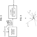
- FIG. 3 shows a method of generating the first estimation model and the second estimation model.
- the first estimation model and the second estimation model are represented as an estimation model 64.
- a training data generator 56 is a simulator which generates a ronchigram.
- the training data generator 56 sequentially generates training data 60 according to a simulation condition 58, while changing the simulation condition 58.
- Each set of training data 60 is formed from a ronchigram 60A and a particular aberration value 60B corresponding thereto.
- the ronchigram 60A is used as input data
- the particular aberration value 60B is used as ground truth data.
- a size of the training data set for the machine learning can be reduced, and a generation time of the training data set for the machine learning can be shortened.
- a learner 62 is formed from, for example, the CNN, and has the estimation model 64.
- a plurality of sets of training data 60 are sequentially supplied to the learner 62, and the contents of the estimation model 64 are improved stepwise. More specifically, a group of parameters of the estimation model 64 are corrected so that, when the ronchigram 60A is supplied to the estimation model 64, the aberration value 60B corresponding to the ronchigram 60A is output from the estimation model 64.
- the estimation model 64 for the in-advance correction When the estimation model 64 for the in-advance correction is generated, a variation width of the particular aberration value included in the simulation condition is set large. On the other hand, when the estimation model 64 for the post correction is generated, the variation width of the particular aberration value included in the simulation condition is set small.
- an estimation model of a low resolution type can be generated as the estimation model 64 for the in-advance correction
- an estimation model of a high resolution type can be generated as the estimation model 64 for the post correction.
- the former estimation model is incorporated as the first estimation model in the first estimator
- the latter estimation model is incorporated as the second estimation model in the second estimator.
- FIG. 4 schematically shows a method of identifying a ronchigram center in the first centering process and the second centering process. The method is executed by the first centering unit and the second centering unit which receive the ronchigram variation image 66.
- a plurality of ronchigrams may be acquired while a defocus value is changed stepwise, and the ronchigrams may be accumulated to generate an accumulated ronchigram as the ronchigram variation image 66.
- the ronchigram variation image 66 may be generated by imaging (integrating) a ronchigram video image while changing the defocus value continuously or stepwise within an imaging period over a certain time period (exposure period).
- the ronchigram variation image may be generated by other methods.
- each point moves approximately radially from the ronchigram center. More specifically, each point moves away from the ronchigram center or toward the ronchigram center.
- a plurality of trajectories are generated by motions of a plurality of points.
- a plurality of straight lines 68 may be extracted by applying a straight line detection method on the ronchigram variation image 66. In this process, known methods may be used such as Hough transform. In FIG. 4 , in order to avoid complications of the drawing, a small number of straight lines 68 are shown. Alternatively, each straight line 68 may be detected as a line segment.
- a plurality of intersections 70 are identified based on the plurality of straight lines 68. Normally, the plurality of intersections 70 are concentrated near a ronchigram center 72. For example, a center of gravity of the plurality of intersections 70 is determined as the ronchigram center 72.
- the variation width of the defocus value (first defocus range) is set large, and, during the execution of the second centering process, the variation width of the defocus value (second defocus range) is set small. That is, the first defocus range is greater than the second defocus range.
- the operation of the deflection scanner is controlled such that the ronchigram center is matched with the imaging center.
- the ronchigram center may be matched with the imaging center by control of other structures.
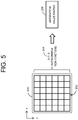
- FIG. 5 is a conceptual diagram showing the SRAM method.
- a segment array 202 is set for a ronchigram 200.
- the segment array 202 is formed from, for example, (n x n) segments arranged in a grid-like manner.
- an autocorrelation function is calculated.
- From the segment array 202 (n x n) autocorrelation functions 204 are determined.
- An aberration value matrix 206 is calculated based on the (n x n) autocorrelation functions 204.
- the aberration value matrix 206 may be calculated based on (n x n) autocorrelation functions 204 calculated from ronchigrams acquired under under-focus conditions, and (n x n) autocorrelation functions 204 calculated from ronchigrams acquired under over-focus conditions.
- FIG. 6 shows an example of a setting image.
- a setting image 74 is displayed on the display prior to start of execution of the aberration correction process.
- a user sets the aberration correction condition on the setting image 74.
- the setting image 74 has a setting area 76 for the first centering process, a setting area 78 for the in-advance correction of the particular aberration, a setting area 80 for the second centering process, a setting area 82 for the primary correction, and a setting area 84 for the post correction of the particular aberration.
- the particular aberration is the second-order coma aberration.
- other aberrations may be set as the particular aberration.
- a two-fold astigmatism may be exemplified.
- a plurality of aberrations may be set as the particular aberration.
- the setting area 76 includes a check box 86, and a defocus range input field 98.
- the defocus range input field 98 is a field for designating a range for changing the defocus value (first defocus range).
- the setting area 78 includes a check box 88, a threshold input field 100, a number input field 102, a defocus value input field 104, and a select button pair 106.
- the threshold input field 100 is a field for designating a threshold (first threshold).
- the number input field 102 is a field for designating a number (first number) serving as a determination value.
- first threshold a number of consecutive occurrences of a phenomenon that the particular aberration value is lower than the first threshold (consecution number) reaches the first number
- the in-advance correction of the particular aberration is completed.
- Each of the first threshold and the first number is a completion condition or a completion parameter.
- the defocus value (first defocus value) which is input in the defocus value input field 104 is set under under-focus or over-focus, selected by the select button pair 106.
- a countermeasure for preventing an infinite loop may be added. For example, a maximum number of loop repetitions may be determined to be a predetermined number (for example, five times).
- the setting area 80 includes a check box 90, and a defocus range input field 108.
- the defocus range input field 108 is a field for designating a range for changing the defocus value (second defocus range).
- the second defocus range is basically smaller than the first defocus range.
- the setting area 82 includes a check box 92, a defocus value input field 110, a repetition number input field 112, and an aberration selection field 114.
- the primary correction is automatically repeatedly executed for a number which is input in the repetition number input field 112.
- a ronchigram is acquired under over-focus and a ronchigram is acquired under under-focus, based on the defocus value which is input in the defocus value input field 110.
- the aberration selection field 114 is for selecting one aberration or a plurality of (group of) aberrations to be corrected. Normally, all aberrations are set as the correction target.
- the setting area 84 includes a check box 94, a threshold input field 116, a number input field 118, a defocus value input field 120, and a selection button pair 122.
- the threshold input field 116 is a field for designating a threshold (second threshold).
- the number input field 118 is a field for designating a number (second number) serving as a determination value.
- the second threshold and the second number is a completion condition or a completion parameter.
- the defocus value which is input in the defocus value input field 120 (second defocus value) is set under under-focus or under over-focus, selected by the selection button pair 122.
- the second threshold is basically smaller than the first threshold.
- the second defocus value is basically smaller than the first defocus value.
- a countermeasure for preventing an infinite loop may be added.
- the first defocus range is larger than the second defocus range
- the first threshold is larger than the second threshold
- the first defocus value is larger than the second defocus value
- the check box 86 may be unchecked, or the check boxes 86 and 90 may be unchecked.
- the check box 88 may be unchecked, or the check boxes 88 and 94 may be unchecked. In this manner, a sequence of steps of the aberration correction process can be customized on the setting image 74.
- the execution of the aberration correction process is started by manipulation of a start button 124.
- the execution of the aberration correction process is stopped by manipulation of a stop button 126.
- FIG. 7 shows the aberration correction process (aberration correction method) of the present embodiment as a flowchart.
- the contents of the flowchart show operations of the information processing unit, and also show the plurality of functions realized by the processor in the information processing unit.
- the aberration correction condition is set by the user on the setting image shown in FIG. 6 .
- the first centering process is executed. The specifics of the process will be described later with reference to FIG. 8 .
- the in-advance correction of the particular aberration is executed. The specifics of the process will be described later with reference to FIG. 9 .
- S20 it is judged whether or not execution of the second centering process is set.
- the second centering process is executed. The specifics of the process will be described later with reference to FIG. 8 .
- the primary correction is repeatedly executed according to the SRAM method.
- each primary correction for example, two aberration value matrices are calculated based on two ronchigrams, and a group of aberrations are corrected based on the two aberration value matrices.
- the group of aberrations can be corrected based on improved ronchigrams, and, thus, the correction precision can be improved.
- the group of aberrations can be corrected with higher precision, based on ronchigrams that are improved to a higher degree.
- an electron microscope image of the sample is acquired. Because the quality of the electron probe can be improved by the execution of the aberration correction process, an electron microscope image having high resolution can be acquired.
- FIG. 8 shows specifics of the first centering process and the second centering process as a flowchart.
- a method described in Document 4 may be utilized.
- an immovable point is determined from cross-correlation of two images acquired while the focus is changed. Because of this, it is difficult to apply the method of Document 4 to an image such as the ronchigram of the amorphous region; that is, an image in which a change other than enlargement and reduction occurs due to focus variation. A stage must be moved so that some object is imaged, and then, the centering process must be executed.
- the method described below is a centering method in which the amorphous region can be set as the observation target without requiring movement of the field of view.
- an electron beam is illuminated onto a sample while the defocus range is stepwise changed within the designated defocus range, to thereby acquire a plurality of ronchigrams.
- a ronchigram variation image is generated as an accumulated image, through accumulation of the ronchigrams.
- the number of accumulations may be, for example, designated within a range of four images to a few tens of images.
- an electron beam may be continuously illuminated onto a sample while the defocus value is continuously changed within the designated defocus range, to thereby image a ronchigram video image as one ronchigram variation image.
- a height of focus is changed by changing an excitation current supplied to the objective lens.
- the height of the focus may be changed by changing a sample position, changing an acceleration voltage of the electron beam, or the like.
- a value corresponding to the exact focus may or may not be included in the defocus range.
- presence or absence of application of the aperture is judged based on the ronchigram variation image.
- an outer region other than a circular region in the ronchigram variation image is removed. This is a first pre-process for improving precision of identifying the ronchigram center.
- the ronchigram variation image may be trimmed stepwise as necessary.
- a filter process is applied to the ronchigram variation image.
- a bandpass filter BPF
- noise included in the ronchigram variation image is removed or reduced, and a non-uniform contrast component (component derived from a composition of the sample, a thickness of the sample, or the like) included in the ronchigram variation image is removed or reduced.
- the filter process is a second pre-process for improving the precision of identifying the ronchigram center.
- each point moves from the ronchigram center to the outer side, or from the outer side toward the ronchigram center. With these movements, a plurality of radial trajectories are generated.
- a plurality of straight lines are detected based on the plurality of radial trajectories.
- a plurality of intersections caused by the plurality of straight lines are identified.
- the ronchigram center is determined based on the plurality of intersections. For example, a center of gravity determined from the plurality of intersections is determined as the ronchigram center.
- an operation of the electron beam illumination system for example, an operation of the deflection scanner, is controlled so that the ronchigram center is matched with the imaging center serving as an immovable point.
- the first centering process basically, the first defocus range, which is large, is set, along with the first threshold, which is large. Therefore, the first centering process is a coarse centering process.
- the second centering process basically, the second defocus range, which is small, is set, along with the second threshold, which is small. Therefore, the second centering process is a fine centering process.
- a centering process of high precision can be realized by stepwise executing the two centering processes with the in-advance correction step of the particular aberration between the centering processes.
- the ronchigram center is identified through image analysis.
- the ronchigram center may be identified using a machine learning type estimator; that is, an AI (Artificial Intelligence) technique.
- AI Artificial Intelligence
- FIG. 9 shows specifics of the in-advance correction and the post correction of the particular aberration as a flowchart.
- a parameter set (threshold, number, defocus value, and defocus type) which is set on the setting image is acquired.
- the first estimation model or the second estimation model is selected as the estimation model to be used.
- the first estimation model is selected, and, in the post correction of the particular aberration, the second estimation model is selected.
- the first estimation model is a model which enables estimation of a relatively large particular aberration, and has a first estimation precision.
- the second estimation model is a model which enables estimation of a relatively small particular aberration, and has a second estimation precision which is higher than the first estimation precision.
- the electron beam is illuminated onto the sample according to the designated defocus value and the designated defocus type, and a ronchigram is thus acquired.
- the size of the ronchigram is adjusted in order to fit the size of the ronchigram to the estimation model.
- the ronchigram is input to the estimator having the estimation model. With this process, an estimated particular aberration value is output from the estimator.
- S70 it is judged whether or not the estimated particular aberration value is lower than a threshold.
- the particular aberration is corrected based on the estimated particular aberration value. Specifically, the operation of the aberration corrector is adjusted so that the particular aberration is reduced. Then, the steps from S64 are again executed.
- the first threshold which is relatively large
- the second threshold which is relatively small
- FIG. 10 shows an example of a ronchigram before the aberration correction process is executed.
- the ronchigram reflects various aberrations, and it is very difficult to identify the ronchigram center in this ronchigram.
- FIG. 11 shows an example of a ronchigram variation image acquired during the first centering process. A striped pattern is present in the ronchigram variation image, and the ronchigram center can be narrowed as an immovable point included in the striped pattern.
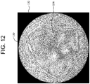
- FIG. 12 shows an example of a ronchigram acquired after the execution of the aberration correction process of the present embodiment (the first centering process, the in-advance correction of the particular aberration, the second centering process, the primary correction, and the post correction of the particular aberration).
- an outer region 132 other than a circular region (aperture region) in a ronchigram 130 is removed.
- the circular region includes a center portion 134 having an almost uniform contrast.
- the center portion 134 has a significantly large size. This shows that the group of aberrations which can be corrected, other than a plurality of higher order aberrations for which the correction is difficult, have been corrected with high precision.
- the correction precision of the group of aberrations can be improved in the electron microscope.
- the burden of the user for the aberration correction can be reduced.
- the algorithm for calculating the aberration value matrix can appropriately function.
- a machine learning type estimator may be used in the first centering process and the second centering process, and an image analyzer different from a machine learning type estimator may be used in the in-advance correction and the post correction of the particular aberration.
- the second-order coma aberration is taken as the particular aberration, but alternatively, a two-fold astigmatism may be taken as the particular aberration, or both the second-order coma aberration and the two-fold astigmatism may be taken as the particular aberration.
- methods other than the SRAM method may be applied.
Landscapes
- Chemical & Material Sciences (AREA)
- Analytical Chemistry (AREA)
- Engineering & Computer Science (AREA)
- Computer Vision & Pattern Recognition (AREA)
- Electron Sources, Ion Sources (AREA)
- Microscoopes, Condenser (AREA)
- Studio Devices (AREA)
- Image Processing (AREA)
Applications Claiming Priority (1)
| Application Number | Priority Date | Filing Date | Title |
|---|---|---|---|
| JP2021120564A JP7382367B2 (ja) | 2021-07-21 | 2021-07-21 | 電子顕微鏡及び収差補正方法 |
Publications (2)
| Publication Number | Publication Date |
|---|---|
| EP4123681A2 true EP4123681A2 (de) | 2023-01-25 |
| EP4123681A3 EP4123681A3 (de) | 2023-03-01 |
Family
ID=82547540
Family Applications (1)
| Application Number | Title | Priority Date | Filing Date |
|---|---|---|---|
| EP22183109.2A Pending EP4123681A3 (de) | 2021-07-21 | 2022-07-05 | Elektronenmikroskop und verfahren zum korrigieren der aberration |
Country Status (3)
| Country | Link |
|---|---|
| US (1) | US12255041B2 (de) |
| EP (1) | EP4123681A3 (de) |
| JP (1) | JP7382367B2 (de) |
Families Citing this family (2)
| Publication number | Priority date | Publication date | Assignee | Title |
|---|---|---|---|---|
| JP7856591B2 (ja) | 2023-02-06 | 2026-05-11 | 株式会社日立製作所 | ロボットの制御方法及びシステム |
| US12531204B2 (en) * | 2023-06-30 | 2026-01-20 | Fei Company | Microscope aberration correction |
Citations (3)
| Publication number | Priority date | Publication date | Assignee | Title |
|---|---|---|---|---|
| JP2006173027A (ja) | 2004-12-20 | 2006-06-29 | Hitachi High-Technologies Corp | 走査透過電子顕微鏡、及び収差測定方法、ならびに収差補正方法 |
| JP4790567B2 (ja) | 2005-11-30 | 2011-10-12 | 日本電子株式会社 | ロンチグラムを用いた収差測定方法及び収差補正方法及び電子顕微鏡 |
| JP4891736B2 (ja) | 2006-11-17 | 2012-03-07 | 日本電子株式会社 | ロンチグラム中心の決定方法 |
Family Cites Families (2)
| Publication number | Priority date | Publication date | Assignee | Title |
|---|---|---|---|---|
| JP2003331773A (ja) * | 2002-05-13 | 2003-11-21 | Jeol Ltd | 電子顕微鏡 |
| US7619220B2 (en) | 2005-11-30 | 2009-11-17 | Jeol Ltd. | Method of measuring aberrations and correcting aberrations using Ronchigram and electron microscope |
-
2021
- 2021-07-21 JP JP2021120564A patent/JP7382367B2/ja active Active
-
2022
- 2022-07-05 EP EP22183109.2A patent/EP4123681A3/de active Pending
- 2022-07-20 US US17/869,117 patent/US12255041B2/en active Active
Patent Citations (3)
| Publication number | Priority date | Publication date | Assignee | Title |
|---|---|---|---|---|
| JP2006173027A (ja) | 2004-12-20 | 2006-06-29 | Hitachi High-Technologies Corp | 走査透過電子顕微鏡、及び収差測定方法、ならびに収差補正方法 |
| JP4790567B2 (ja) | 2005-11-30 | 2011-10-12 | 日本電子株式会社 | ロンチグラムを用いた収差測定方法及び収差補正方法及び電子顕微鏡 |
| JP4891736B2 (ja) | 2006-11-17 | 2012-03-07 | 日本電子株式会社 | ロンチグラム中心の決定方法 |
Non-Patent Citations (1)
| Title |
|---|
| H. SAWADA ET AL.: "Measurement method of aberration from Ronchigram by autocorrelation function", ULTRAMICROSCOPY, vol. 108, 2008, pages 1467 - 1475, XP025471300, DOI: 10.1016/j.ultramic.2008.04.095 |
Also Published As
| Publication number | Publication date |
|---|---|
| US12255041B2 (en) | 2025-03-18 |
| EP4123681A3 (de) | 2023-03-01 |
| US20230026970A1 (en) | 2023-01-26 |
| JP2023016326A (ja) | 2023-02-02 |
| JP7382367B2 (ja) | 2023-11-16 |
Similar Documents
| Publication | Publication Date | Title |
|---|---|---|
| JP5103532B2 (ja) | 収差補正器を備えた荷電粒子線装置 | |
| US12255041B2 (en) | Electron microscope and method of correcting aberration | |
| US20040124364A1 (en) | Charged particle beam alignment method and charged particle beam apparatus | |
| JP4790567B2 (ja) | ロンチグラムを用いた収差測定方法及び収差補正方法及び電子顕微鏡 | |
| JP5603421B2 (ja) | 自動収差補正法を備えた荷電粒子線装置 | |
| JP5188846B2 (ja) | 走査型透過電子顕微鏡の収差補正装置及び収差補正方法 | |
| JP2006196236A (ja) | 電子顕微鏡及び観察方法 | |
| JP7716152B2 (ja) | 顕微鏡のオートフォーカスおよび非点収差補正方法 | |
| JP4857101B2 (ja) | プローブ評価方法 | |
| JP2016004713A (ja) | 収差計測角度範囲計算装置、収差計測角度範囲計算方法、および電子顕微鏡 | |
| JP2025061614A (ja) | 荷電粒子ビーム顕微鏡法における光学収差の測定及び補正 | |
| US7633063B2 (en) | Charged particle beam apparatus | |
| EP4044210A1 (de) | Verfahren zur erzeugung eines schätzungsmodells und elektronenmikroskop | |
| JP5178558B2 (ja) | 荷電粒子線の光軸調整方法、及び荷電粒子線装置 | |
| EP3905302B1 (de) | Rastertransmissionselektronenmikroskop und einstellungsverfahren eines optischen systems | |
| JP2014056788A (ja) | 荷電粒子線装置、及び収差補正方法 | |
| JP2015056376A (ja) | 走査透過電子顕微鏡及びその収差測定方法 | |
| JP2021176143A (ja) | 走査透過電子顕微鏡および光学系の調整方法 | |
| CN114628210A (zh) | 带电粒子束装置 | |
| JP7636455B2 (ja) | 電子顕微鏡、収差補正方法、および撮像方法 | |
| JP7292496B2 (ja) | 荷電粒子線システム | |
| JP5228463B2 (ja) | 電子線装置、電子線形状測定方法及び画像処理方法 | |
| WO2026009262A1 (ja) | 荷電粒子線装置および収差計測方法 | |
| JP2019160464A (ja) | 電子顕微鏡および調整方法 | |
| JP2010251128A (ja) | 透過型電子顕微鏡の自動最適合焦点調整方法及び装置 |
Legal Events
| Date | Code | Title | Description |
|---|---|---|---|
| PUAI | Public reference made under article 153(3) epc to a published international application that has entered the european phase |
Free format text: ORIGINAL CODE: 0009012 |
|
| STAA | Information on the status of an ep patent application or granted ep patent |
Free format text: STATUS: THE APPLICATION HAS BEEN PUBLISHED |
|
| AK | Designated contracting states |
Kind code of ref document: A2 Designated state(s): AL AT BE BG CH CY CZ DE DK EE ES FI FR GB GR HR HU IE IS IT LI LT LU LV MC MK MT NL NO PL PT RO RS SE SI SK SM TR |
|
| REG | Reference to a national code |
Ref country code: DE Ref legal event code: R079 Free format text: PREVIOUS MAIN CLASS: H01J0037220000 Ipc: H01J0037153000 |
|
| PUAL | Search report despatched |
Free format text: ORIGINAL CODE: 0009013 |
|
| AK | Designated contracting states |
Kind code of ref document: A3 Designated state(s): AL AT BE BG CH CY CZ DE DK EE ES FI FR GB GR HR HU IE IS IT LI LT LU LV MC MK MT NL NO PL PT RO RS SE SI SK SM TR |
|
| RIC1 | Information provided on ipc code assigned before grant |
Ipc: H01J 37/28 20060101ALI20230126BHEP Ipc: H01J 37/153 20060101AFI20230126BHEP |
|
| STAA | Information on the status of an ep patent application or granted ep patent |
Free format text: STATUS: REQUEST FOR EXAMINATION WAS MADE |
|
| 17P | Request for examination filed |
Effective date: 20230721 |
|
| RBV | Designated contracting states (corrected) |
Designated state(s): AL AT BE BG CH CY CZ DE DK EE ES FI FR GB GR HR HU IE IS IT LI LT LU LV MC MK MT NL NO PL PT RO RS SE SI SK SM TR |