EP4123679A1 - Lichtbogenlöschanordnung und damit versehener schutzschalter - Google Patents
Lichtbogenlöschanordnung und damit versehener schutzschalter Download PDFInfo
- Publication number
- EP4123679A1 EP4123679A1 EP21772157.0A EP21772157A EP4123679A1 EP 4123679 A1 EP4123679 A1 EP 4123679A1 EP 21772157 A EP21772157 A EP 21772157A EP 4123679 A1 EP4123679 A1 EP 4123679A1
- Authority
- EP
- European Patent Office
- Prior art keywords
- arc
- electromagnet
- arc extinguishing
- circuit breaker
- extinguishing assembly
- Prior art date
- Legal status (The legal status is an assumption and is not a legal conclusion. Google has not performed a legal analysis and makes no representation as to the accuracy of the status listed.)
- Pending
Links
Images




Classifications
-
- H—ELECTRICITY
- H01—ELECTRIC ELEMENTS
- H01H—ELECTRIC SWITCHES; RELAYS; SELECTORS; EMERGENCY PROTECTIVE DEVICES
- H01H73/00—Protective overload circuit-breaking switches in which excess current opens the contacts by automatic release of mechanical energy stored by previous operation of a hand reset mechanism
- H01H73/02—Details
- H01H73/18—Means for extinguishing or suppressing arc
-
- H—ELECTRICITY
- H01—ELECTRIC ELEMENTS
- H01H—ELECTRIC SWITCHES; RELAYS; SELECTORS; EMERGENCY PROTECTIVE DEVICES
- H01H71/00—Details of the protective switches or relays covered by groups H01H73/00 - H01H83/00
- H01H71/10—Operating or release mechanisms
- H01H71/12—Automatic release mechanisms with or without manual release
- H01H71/24—Electromagnetic mechanisms
- H01H71/2481—Electromagnetic mechanisms characterised by the coil design
-
- H—ELECTRICITY
- H01—ELECTRIC ELEMENTS
- H01H—ELECTRIC SWITCHES; RELAYS; SELECTORS; EMERGENCY PROTECTIVE DEVICES
- H01H9/00—Details of switching devices, not covered by groups H01H1/00 - H01H7/00
- H01H9/30—Means for extinguishing or preventing arc between current-carrying parts
- H01H9/44—Means for extinguishing or preventing arc between current-carrying parts using blow-out magnet
-
- H—ELECTRICITY
- H01—ELECTRIC ELEMENTS
- H01H—ELECTRIC SWITCHES; RELAYS; SELECTORS; EMERGENCY PROTECTIVE DEVICES
- H01H9/00—Details of switching devices, not covered by groups H01H1/00 - H01H7/00
- H01H9/30—Means for extinguishing or preventing arc between current-carrying parts
- H01H9/44—Means for extinguishing or preventing arc between current-carrying parts using blow-out magnet
- H01H9/443—Means for extinguishing or preventing arc between current-carrying parts using blow-out magnet using permanent magnets
-
- H—ELECTRICITY
- H01—ELECTRIC ELEMENTS
- H01H—ELECTRIC SWITCHES; RELAYS; SELECTORS; EMERGENCY PROTECTIVE DEVICES
- H01H71/00—Details of the protective switches or relays covered by groups H01H73/00 - H01H83/00
- H01H71/10—Operating or release mechanisms
- H01H71/12—Automatic release mechanisms with or without manual release
- H01H71/24—Electromagnetic mechanisms
- H01H2071/249—Electromagnetic mechanisms with part of the magnetic circuit being in the normal current path in the circuit breaker, e.g. yoke, fixed contact and arc-runner are made out of one single conductive element
-
- H—ELECTRICITY
- H01—ELECTRIC ELEMENTS
- H01H—ELECTRIC SWITCHES; RELAYS; SELECTORS; EMERGENCY PROTECTIVE DEVICES
- H01H9/00—Details of switching devices, not covered by groups H01H1/00 - H01H7/00
- H01H9/30—Means for extinguishing or preventing arc between current-carrying parts
- H01H9/34—Stationary parts for restricting or subdividing the arc, e.g. barrier plate
- H01H9/342—Venting arrangements for arc chutes
-
- H—ELECTRICITY
- H01—ELECTRIC ELEMENTS
- H01H—ELECTRIC SWITCHES; RELAYS; SELECTORS; EMERGENCY PROTECTIVE DEVICES
- H01H9/00—Details of switching devices, not covered by groups H01H1/00 - H01H7/00
- H01H9/30—Means for extinguishing or preventing arc between current-carrying parts
- H01H9/46—Means for extinguishing or preventing arc between current-carrying parts using arcing horns
Definitions
- the present invention relates to an arc extinguishing assembly in which a magnet is installed to effectively extinguish an arc generated by blocking an electric current, and a circuit breaker including the same.
- a circuit breaker is a device that blocks the flow of current when abnormal current such as electrical leakage, short circuit or excessive current occurs in the circuit. Through this, it is possible to prevent an accident that may occur in a circuit or an electronic device connected to the circuit.
- the circuit breaker is energably installed at a specific position in the circuit such that the current of the circuit passes through the circuit breaker.
- the circuit breaker is connected such that when a normal current flows, the movable contact point is in contact with the stationary contact point, and when the movable contact point and the stationary contact point are in contact with each other, the circuit can conduct electricity.
- the movable contact point and the stationary contact point in contact are spaced apart from each other. In this case, the current flowing between the movable contact point and the stationary contact point is not immediately extinguished, but is changed in the form of an arc and is extended along the movable contact point.
- the arc is a flow of high-temperature and high-pressure electrons, and when the generated arc stays in the circuit breaker for a long period of time, there is a risk of damage to each component of the circuit breaker. In addition, when the arc is discharged to the outside of the circuit breaker without a separate treatment process, there is a risk of injury to the user.
- the circuit breaker is provided with an arc extinguishing assembly for discharging while extinguishing the arc.
- the generated arc is passed through the extinguishing device, the arc pressure is increased, the moving speed is increased, and it is cooled at the same time and can be discharged to the outside.
- a conventional circuit breaker ( Korean Utility Model Application No. 20-2008-0009468 ) discloses the structure of an air circuit breaker, which is stacked with a certain gap in the arc chamber and includes a grid in which an induction groove is formed such that a contact point can be located, and a grid plate which is provided on the side wall of the guide groove of the grid
- Such a circuit breaker can induce an arc toward the grid through the guide plate, but in the case of a small current where the magnitude of the current is not large, there is a problem in that it is difficult to create a movement path of the arc along the grid because the generated pressure is not large.
- An object of the present invention is to provide the structure of an arc extinguishing assembly in which the generated arc can be extended to a grid and a runner.
- Another object of the present invention is to provide the structure of an arc extinguishing assembly that is capable of pushing the arc generated by the magnetic field generated by the magnet toward the runner by arranging the magnet inside such that the movement path of the arc is smoothly formed even when a small current is applied.
- Still another object of the present invention is to provide the structure of an arc extinguishing assembly in which a magnet for forming the movement path of an arc can be stably installed, and excessive design changes are unnecessary for the installation of the magnet.
- the arc extinguishing assembly which can solve the above-described problems may include side members which are spaced apart by a certain distance and disposed to face each other; an exhaust which is installed on an upper part of the side member; a plurality of grids which are installed between the side members and having both ends fixed to each of the side members; an arc guide having one side coupled to the side member and installed under the plurality of grids; and a magnet which is installed such that both ends are respectively coupled to the side members under the plurality of grids, and forms an electromagnetic force in a direction toward the grid.
- the magnet may include an electromagnet having both sides fixed to a lower part of the side member, respectively, and forming a magnetic field by being magnetized by an electric current; and a permanent magnet which is installed inside the electromagnet and rotates in a direction crossing an extension direction of the electromagnet.
- the electromagnet may include a core which is made of a cylindrical magnetizable material; and a coil which is formed to extend in a shape surrounding an outer surface of the core.
- fixing shafts are formed to protrude so as to be supported by being fitted to an inner surface of each of the side members.
- the fixing shaft may pass through the arc guide and be seated in a fixing groove formed in the side member.
- the permanent magnet may be located in a permanent magnet accommodating portion consisting of a space formed inside the electromagnet.
- the permanent magnet may be composed of at least one. According to an example of the present invention, the magnet may be fixed to both sides of the arc guide, respectively.
- the arc extinguishing assembly may further include an arc runner which is inserted between the side members, is spaced apart from one side of the plurality of grids by a certain distance, and is formed to be bent toward a lower part of the grid.
- the magnet may be installed such that both ends are respectively coupled to the side member at positions that are spaced apart from the arc guide by a certain distance.
- an insulating material may be included on an outer surface of the side member.
- the circuit breaker according to the present invention which can solve the above-described problems may include a stationary contact; a movable contact that moves in a direction toward the stationary contact or a direction away from the stationary contact; and an arc extinguishing assembly which is located adjacent to the stationary contact and the movable contact so as to extinguish an arc which is generated by the stationary contact and the movable contact being spaced apart, wherein the arc extinguishing assembly may include side members which are spaced apart by a certain distance and disposed to face each other; an exhaust which is installed on an upper part of the side member; a plurality of grids which are installed between the side members and having both ends fixed to each of the side members; an arc guide having one end coupled to the side member and installed under the plurality of grids; and a magnet which is installed such that both ends are respectively coupled to the side members under the plurality of grids, and forms an electromagnetic force in a direction toward the grid.
- the magnet may include an electromagnet having both sides fixed to a lower part of the side member, respectively, and forming a magnetic field by being magnetized by an electric current; and a permanent magnet which is installed inside the electromagnet and rotates in a direction crossing an extension direction of the electromagnet.
- the electromagnet may include a core which is made of a cylindrical magnetizable material; and a coil which is formed to extend in a shape surrounding an outer surface of the core.
- the permanent magnet may be located in a permanent magnet accommodating portion consisting of a space formed inside the electromagnet.
- the permanent magnet may be composed of at least one.
- the generated arc receives a force toward the arc runner by the electromagnetic force formed by the magnet, and the arc extension speed is increased in a direction toward the arc runner such that the arc extinguishing performance can be further improved.
- the arc extinguishing performance can be secured without significantly changing the design structure of an arc extinguishing assembly.
- both sides of the electromagnet can be stably fixed between the side members, respectively, and since at least one permanent magnet is installed in the space formed inside the electromagnet, it is possible to achieve the advantages of securing a greater electromagnetic force and securing the space.
- a singular representation may include a plural representation unless it represents a definitely different meaning from the context.
- FIG. 1 is a perspective view showing the state of the circuit breaker 10, and FIG. 2 is an exploded perspective view of the circuit breaker 10.
- FIG. 3 is a cross-sectional view of the circuit breaker 10 taken along line A-A'.
- the circuit breaker 10 serves to block the flow of current when an abnormal current is generated, and may refer to an air circuit breaker.
- the air circuit breaker is a type of circuit breaker, meaning the current in a state where the circuit breaker performs a blocking operation, and when an abnormal current exceeding a preset current range value leaks from the circuit breaker, it is a device that blocks the flow of the current in a circuit.
- the circuit breaker 10 includes a circuit breaker body 11 which forms an exterior and has an accommodation space formed therein.
- a plurality of arc extinguishing assemblies 100 may be installed inside the circuit breaker body 11.
- the circuit breaker body 11 is coupled to a front side cover 11b and a rear side cover 11a in a direction facing each other to form an inner space.
- the circuit breaker body 11 may be formed of a material having high heat resistance and high rigidity. This is to prevent damage to each component mounted therein, and to prevent damage by an arc generated inside.
- the circuit breaker body 11 may be made of synthetic resin or reinforced plastic.
- the internal space of the circuit breaker body 11 may conduct electricity with the outside, and each component mounted therein may be connected to conduct electricity with an external power source or a load.
- a power supply side connection portion 12a connected to the power supply side so as to conduct electricity, and a load side connection portion 12b connected to the load side to conduct electricity with the power supply side may be respectively installed in the front part of the circuit breaker body 11.
- the stationary contact 13 and the movable contact 14 for blocking or conducting electricity with the power supply side connection portion 12a and the load side connection portion 12b may be respectively installed.
- a stationary contact point 13a may be formed in the stationary contact 13, and a movable contact point 14a may be formed in the movable contact 14. Accordingly, when a normal current flows in the circuit, the stationary contact point 13a and the movable contact point 14a are in contact with each other such that a current may flow between the power supply side connection portion 12a and the load side connection portion 12b.
- a shooter 21 may be configured to rotate together as the movable contact 14 is rotated away from the stationary contact 13.
- the shooter 21 may be installed to be connected to a crossbar 22 and a lever 23. Specifically, one end of the shooter 21 is restrained by the crossbar 22, and an elastic member is provided at the other end of the shooter 21.
- the shooter 21 presses the elastic member and stores a restoring force.
- the external force for pressing may be provided by a state where the crossbar 22 is rotated toward the stationary contact 13.
- the movable contact point 14a When the movable contact point 14a is located to be spaced apart from the stationary contact point 13a, the movable contact 14 is rotated in a direction away from the stationary contact point 13.
- the crossbar 22 may be rotated, and specifically, one end of the shooter 21 is released such that it may be rotated by a restoring force provided by the elastic member.
- the shooter 21 rotates and hits the lever 23, the lever 23 is also rotated, and a trip mechanism may be performed.
- the lever 23 is partially exposed to the outside of the air circuit breaker 10, and the lever 23 may be rotated by hitting the rotated shooter 21.
- the lever 23 may be rotated in a preset direction, and the user may easily recognize that the trip mechanism has been performed.
- the user may rotate the lever 23 to adjust the air circuit breaker 10 to a state that can conduct electricity again.
- the movable contact 14 when an abnormal current flows in the circuit, the movable contact 14 is rotated by a predetermined angle in a direction away from the stationary contact 13, and as the stationary contact point 13a and the movable contact point 14a are spaced apart from each other, the flow of current may be blocked.
- the arc is a plasma of high-temperature electrons and ions, and when the generated arc stays in the internal space of the circuit breaker for a long period of time, there is a risk of damage to each component of the circuit breaker.
- the circuit breaker 10 is provided with an extinguishing device for discharging while extinguishing the arc such that the generated arc passes through the extinguishing device, the arc pressure is increased, the moving speed is increased, and the arc is cooled at the same time and discharged to the outside.
- the arc extinguishing assembly 100 for extinguishing the arc generated above the stationary contact point 13a and the movable contact point 14a may be installed.
- FIG. 4 is a perspective view showing the state of an arc extinguishing assembly 100
- FIG. 5 is an exploded perspective view of the arc extinguishing assembly 100 of FIG. 4 .
- the arc extinguishing assembly 100 may be inserted and installed on an open side of the accommodation space formed inside the circuit breaker body 11 as described above.
- the arc generated in the circuit breaker 10 is extinguished by the arc extinguishing assembly 100 and then discharged to the outside of the breaker 10 through the exhaust 120 of the arc extinguishing assembly 100.
- the arc is extended in the course of flowing through a grid 130 and an arc runner 140 of the arc extinguishing assembly 100.
- the arc extinguishing assembly 100 includes a pair of side members 111 coupled to an exhaust 120, a grid 130, an arc runner 140 and an arc guide 150.
- the exhaust 120 for discharging the extinguished arc may be formed on a plurality of grids 130.
- the exhaust 120 functions as a passage through which the metal gas is discharged to the outside of the circuit breaker 10.
- the exhaust 120 includes an exhaust body 124, an insulating plate 123, a filter 122 and an exhaust cover 121.
- a pair of side members 111 are coupled to the left and right sides of the exhaust body 124, respectively, and an accommodating portion (not assigned) in which an insulating plate 123 and a filter 122 are accommodated in the central part of the upper surface of the exhaust body 124 may be formed to be recessed, and a plurality of exhaust holes (not assigned) may be formed to pass through the insulating plate 123.
- An exhaust cover 121 is coupled to an upper side surface of the exhaust body 124, and a plurality of gas outlets (not assigned) may be formed through a central part of the exhaust cover 121.
- the insulating plate 123, the filter 122 and the exhaust cover 121 are sequentially located from the lower side to the upper side. Accordingly, the metal gas introduced into the exhaust hole (not illustrated) of the insulating plate 123 may be discharged to the outside of the circuit breaker 10 through a gas outlet (not illustrated) after passing through the filter 122.
- the arc extinguishing assembly 100 may be coupled to the body 11 of the circuit breaker 10 through the exhaust 120.
- Fastening holes are respectively formed on the front side and the rear side of the exhaust cover 121, and in a state where the exhaust cover 121 covers the opening of the accommodation space (S1) of the circuit breaker 10, a fastening member (not illustrated) may be coupled to the circuit breaker body 11 through the fastening hole.
- the exhaust 120 functions as a pressure raising means inside the arc extinguishing assembly 100. Specifically, the exhaust 120 covers the opening of the accommodation space (S1) such that the pressure inside the arc extinguishing assembly 100 may momentarily increase when the metal gas is generated. In this case, a temporary pressure difference is generated between the pressure inside the arc extinguishing assembly 100 and the outside of the circuit breaker 10, and the metal gas may move toward the exhaust hole of the exhaust 120.
- the side members 111 are spaced apart from each other by a certain distance and may be formed in a pair of plate shapes disposed to face each other.
- a grid 130 and an arc runner 140 are disposed between the side members 111.
- a grid fastening hole 111b and an arc runner fastening hole may be formed through the central part of the side member 111.
- a grid fastening protrusion (not illustrated) and an arc runner fastening protrusion (not illustrated) may be respectively inserted into the grid fastening hole 111b and the arc runner fastening hole (not illustrated).
- the grid fastening hole 111b and the arc runner fastening hole (not illustrated) may be formed to have sizes corresponding to the grid fastening protrusion (not illustrated) and the arc runner fastening protrusion (not illustrated) or slightly smaller sizes. Accordingly, the grid fastening protrusion and the arc runner fastening protrusion may be press-fitted into the grid fastening hole 111b and the arc runner fastening hole (not illustrated), respectively.
- An arc guide 150 may be coupled to each side member 111, respectively.
- An arc guide fastening hole 111c for coupling with the arc guide 150 is formed to pass through the lower side of the side member 111.
- the arc guide fastening hole 111c may be formed in the shape of a cylindrical hole formed to pass through one side of the side member 111.
- a fixing shaft support groove 111d may be formed in the side member 111 such that the fixing shaft 213 of the core 211 is located at a position spaced apart from the arc guide fastening hole 111c by a predetermined distance.
- One side surface of the arc guide 150 is located to be in close contact with the side member 111.
- an arc guide fastening portion 151 may be formed to protrude in a direction toward the side member 111 on one side surface of the arc guide 150.
- a fixing shaft insertion hole 152 for fixing the core 211 to a position spaced apart from the arc guide fastening portion 151 may be formed on the one side surface.
- the arc guide fastening portion 151 protruding from the arc guide 150 is coupled to the arc guide fastening hole 111c such that the arc guide 150 may be coupled to the side member 111.
- the fixing shaft 213 of the core 211 is inserted into the fixing shaft insertion hole 152 formed in the arc guide 150, and the fixing shaft 213 will be located in the fixing shaft support groove 111d.
- a screw fastening hole 111a for coupling with the exhaust 120 is formed on the upper side of the side member 111 such that the pair of side members 111 may be coupled to the exhaust 120, respectively.
- a screw coupling groove (not illustrated) for coupling with the side member 111 may be formed in the exhaust body 124.
- a fastening screw (not illustrated) passes through the screw fastening hole 111a and is coupled to the screw fastening groove 124a.
- the grids 130 are formed in a plate shape and spaced apart from each other by a predetermined distance in one direction away from the stationary contact point 13a, and has a structure in which a plurality of grids are stacked.
- Grid fastening protrusions are formed to protrude from both sides of the grid 130 and are located to be inserted into the grid fastening holes 111b.
- the grid 130 may be fixed between the pair of side members 111.
- the grid 130 may be made of any material capable of applying electromagnetic attraction to the arc, and for example, it may be made of iron (Fe).
- the arc voltage is increased and the arc may be cooled.
- the arc runner 140 is formed in a plate shape, and may be spaced apart from the plurality of grids 130 by a predetermined distance in the rear side.
- the generated arc extends to the lower end of the arc runner 140 and flows along the arc runner 140. If the arc does not reach the arc runner 140, the arc extinguishing performance may be reduced, and the lower end of the arc runner 140 may be formed in a curved shape toward the stationary contact point 13a.
- the lower end of the curved arc runner 140 is located below the grid 130 which is located on the rear side among the plurality of grids 130. Due to the curved structure of the arc runner 140, the distance between the lower end of the arc runner 140 and the stationary contact point 13a may be shortened.
- the arc runner 140 may be formed of any material capable of applying electromagnetic attraction to the arc, and for example, the arc runner may be formed of an iron (Fe) material.
- the arc guide 150 is provided as a pair and may be respectively coupled to the pair of side members 111 at the lower side of the grid 130.
- the arc guide 150 may be formed of an insulating material and may be formed to extend along the stacking direction of the grid 130. That is, the arc guide 150 may be formed to extend in a direction away from the stationary contact point 13a.
- the arc guide 150 may have a shape extending from the lower side of the grid 130 to the rear side.
- the arc guide 150 may be made of a pair of members installed to face each other, and may be made to reduce the size of a space formed between each member. Accordingly, it will be possible to reduce the dispersion of the metal gas generated at the stationary contact point when an abnormal current is generated.
- each member (not illustrated) constituting the arc guide 150 is made such that the distance therebetween increases from the front side to the rear side, and thus, the size of the space between the pair of members will be able to increase from the front side to the rear side.
- the arc extinguishing assembly 100 may include a magnet 200.
- the magnet 200 is located below the side member 111 and may be disposed between each arc guide 150 disposed to face each other.
- the magnet 200 is installed in the arc extinguishing assembly 100 and serves to induce the movement of the generated arc.
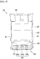
- FIG. 6 is a longitudinal cross-sectional view of the arc extinguishing assembly 100
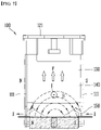
- FIG. 7 is a conceptual diagram illustrating a state where a magnetic field is formed by the magnet 200.
- FIG. 8a is a perspective view showing a state where the permanent magnet 220 is coupled to the electromagnet 210
- FIG. 8b is a conceptual diagram showing a state when a current flows in the magnet 200.
- the movable contact point 14a and the stationary contact point 13a are spaced apart from the lower side of the arc extinguishing assembly 100, an arc is generated.
- the arc may extend along the movable contact point 14a.
- Metal gas is generated between the movable contact point 14a and the stationary contact point 13a, and the pressure of the part of the stationary contact point 13a is momentarily increased, and the arc is extended toward the grid 130 and the arc runner 140 by the pressure difference.
- the extended arc reaches the plurality of grids 130 and the arc runner 140, and the arc is extended upward and cooled while flowing along the grid 130 and the arc runner 140.
- the arc extinguishing assembly 100 may include a magnet 200 installed on the lower side of the side member 111.
- the magnet 200 is installed at a position adjacent to the arc guide 150, and the magnet 200 serves to form a magnetic field in a direction toward the grid 130.
- the magnet 200 may move the generated arc toward the grid 130 and the arc runner 140.
- the magnet 200 may include an electromagnet 210 and a permanent magnet 220.
- the electromagnet 210 may include a core 211 made of a cylindrical ferromagnetic material and a coil 212 installed to surround the outer surface of the core 211.
- the core 211 may be made of a cylindrical magnetizable material extending in one direction, and the core 211 may be magnetized by a current flowing through the coil 212 to form a magnetic field.
- the core 211 may form a different direction of the electromagnetic force generated according to the direction of the current flowing through the coil 212.
- the current may flow in the core 211 in a clockwise or counterclockwise direction.
- the left part of the electromagnet 210 may be magnetized to the N pole and the right part thereof may be magnetized to the S pole.
- the right side of the electromagnet 210 in the drawing may be magnetized to the N pole, and the left side thereof may be magnetized to the S pole.
- the magnetic field formed by the electromagnet 210 acts on the arc, and the arc may be applied in a direction toward the top of the arc extinguishing assembly 100 force. Accordingly, the arc will be able to be extinguished more smoothly on the grid 130.
- fixing shafts 213 may be formed to protrude to be inserted into and supported by the inner surface of the side member 111, respectively. Each fixing shaft 213 may be fixedly seated on the inner surface of the side member 111.
- the fixing shaft 213 may be located to pass through the fixing shaft insertion hole 152 formed in the arc guide 150 to be seated in the fixing shaft support groove 111d formed in the side member 111.
- the core 211 may be installed in a position adjacent to the arc guide 150 and spaced apart by a predetermined distance.
- the fixing shaft 213 formed in the core 211 may be directly coupled to the fixing shaft support groove 111d formed in the side member 111 at a position spaced apart from the arc guide 150 by a certain distance. That is, the core 211 may be directly fixedly installed on the side member 111 without contacting the arc guide 150.
- an arc guide fastening portion 151 may be formed to protrude in a direction toward the side member 111 on one side surface of the arc guide 150.
- the arc guide fastening portion 151 may be formed in plurality, and in this case, a plurality of arc guide fastening holes 111c may be formed in the side member 111 to correspond to each arc guide fastening portion 151.
- the core 211 of the electromagnet 210 when a current (I) is applied along the coil 212, the core 211 of the electromagnet 210 is magnetized to the S pole on the right side of the drawing and the N pole on the left side thereof to form a magnetic field.
- the core 211 of the electromagnet 210 is magnetized while the current (I) moves along the coil 212, the side member 111 in contact therewith may also be magnetized, thereby increasing the strength of the magnetic field.
- the side member 111 may be made of a ferromagnetic material such as iron (Fe) as a metal.
- the side member 111 may be magnetized by the magnet 200, thereby forming a larger magnetic field together with the magnet 200.
- the arc moving along the grid 130 will move through the side member 111.
- an insulating material (not illustrated) may be applied to the outer surfaces of the side members 111 located on both sides of the plurality of grids 130.
- the insulating material may form a certain layer by covering or applying the outer exposed surface of the side member 111.
- the insulating material refers to a non-metallic material, and may mean any one of a polyresin such as plastic, rubber and a non-metallic material.
- the direction of the current flowing in the coil 212 surrounding the core 211 of the electromagnet 210 is in the opposite direction to that described above, and thus, it will be possible to apply a force in a direction toward the top of the arc extinguishing assembly 100 for the arc generated in the circuit breaker 10.
- the magnet 200 may include a permanent magnet 220 capable of forming an electromagnetic force in the same direction as the electromagnetic force formed by the electromagnet 210.
- the permanent magnet 220 may have a cylindrical shape, and may include a first pole 221, a second pole 222 and a rotation shaft 223 which is located on the core 211 of the electromagnet to rotate.
- the permanent magnet 220, the first pole 221 and the second pole 222 may be made of an S pole or an N pole having different polarities, which functions to increase the magnitude of the magnetic field according to the magnetization of the electromagnet 210.
- the permanent magnet 220 may be installed inside the electromagnet 210.
- the electromagnet 210 may have a permanent magnet accommodating portion 214 formed of a predetermined space such that the permanent magnet may be accommodated.
- the permanent magnet 220 may rotate in a direction intersecting the extending direction of the electromagnet 210 in a state where it is located in the permanent magnet accommodating portion 214.
- the permanent magnet 220 may rotate based on the rotation shaft 223, and the size of the magnetic flux formed in the electromagnet 210 may be augmented.
- the pressure of the part where the metal gas is generated is momentarily increased, and as a result, the metal gas is raised toward the exhaust 120 of the arc extinguishing assembly 100 by the pressure difference. As a result, the arc flowing through the metal gas is raised and extended in an arcuate shape.
- the generated arc passes through the space between the arc guides 150 and moves to the grid 130 and the arc runner 140, and undergoes the extinguishing process in the grid 130 and the arc runner 140 so as to be discharged to the outside of the circuit breaker 10.
- the generated arc is a flow of high-temperature and high-pressure electrons and is preferably discharged to the outside of the circuit breaker 10 within a short period of time. To this end, it is preferable that the generated arc is rapidly extended from the stationary contact point 13a to the farthest arc runner 140 and then rapidly extended toward the exhaust 120.
- the electromagnet 210 and the electromagnet 210 are installed at a position adjacent to the arc guide 150 between the side members 111 located to face each other.
- the permanent magnet 220 installed in the arc it is possible to smoothly extend to the arc runner 140.
- FIG. 9 shows a state of the arc extinguishing assembly 100 according to another exemplary embodiment of the present invention.
- the arc extinguishing assembly 100 has the same structure as the arc extinguishing assembly 100 described above, except for the magnet 200 having a modified structure.
- a plurality of permanent magnets 220a, 220b, 220c may be installed in the electromagnet 210 of the magnet 200.
- a plurality of permanent magnet accommodating portions 214 are formed in the core 211 constituting the electromagnet 210 to accommodate each of the permanent magnets 220a, 220b, 220c.
- a plurality of permanent magnets 220a, 220b, 220c may mean two or more permanent magnets, and for example, as shown in FIG. 9 , it will be possible to consist of three permanent magnets. However, this is only one example, and the number of permanent magnets may be selected by the user in consideration of the width and length of the core.
- the arc Since the upward force acting on the arc increases by the electromagnetic force formed by the plurality of permanent magnets 220a, 220b, 220c, the arc is extended more rapidly on the grid 130 and the arc runner 140, and as a result, the arc extinguishing performance may be improved.
- the momentary pressure increase generated according to the separation between the stationary contact point 13a and the movable contact point 14a is relatively small, and thus, the arc does not reach the arc runner 140, and the arc extinguishing performance may be deteriorated.
- the electromagnetic force is applied to the arc together with the electromagnet 210 such that it is more smoothly extended to the arc runner 140.
- the arc extinguishing assembly described above and the circuit breaker including the same are not limited to the configuration and method of the above-described exemplary embodiments, but the exemplary embodiments may be configured by selectively combining all or part of each exemplary embodiment such that various modifications may be made.
- the present invention has industrial applicability, because it is possible to provide an arc extinguishing assembly in which a magnet is installed to effectively extinguish an arc generated by blocking an electric current, and a circuit breaker including the same.
Landscapes
- Physics & Mathematics (AREA)
- Electromagnetism (AREA)
- Arc-Extinguishing Devices That Are Switches (AREA)
- Breakers (AREA)
Applications Claiming Priority (2)
| Application Number | Priority Date | Filing Date | Title |
|---|---|---|---|
| KR1020200034575A KR102556750B1 (ko) | 2020-03-20 | 2020-03-20 | 아크 소호 조립체 및 이를 포함하는 차단기 |
| PCT/KR2021/002589 WO2021187774A1 (ko) | 2020-03-20 | 2021-03-03 | 아크 소호 조립체 및 이를 포함하는 차단기 |
Publications (2)
| Publication Number | Publication Date |
|---|---|
| EP4123679A1 true EP4123679A1 (de) | 2023-01-25 |
| EP4123679A4 EP4123679A4 (de) | 2024-04-10 |
Family
ID=77768432
Family Applications (1)
| Application Number | Title | Priority Date | Filing Date |
|---|---|---|---|
| EP21772157.0A Pending EP4123679A4 (de) | 2020-03-20 | 2021-03-03 | Lichtbogenlöschanordnung und damit versehener schutzschalter |
Country Status (6)
| Country | Link |
|---|---|
| US (1) | US12154746B2 (de) |
| EP (1) | EP4123679A4 (de) |
| JP (1) | JP7439292B2 (de) |
| KR (1) | KR102556750B1 (de) |
| CN (1) | CN115315771B (de) |
| WO (1) | WO2021187774A1 (de) |
Families Citing this family (1)
| Publication number | Priority date | Publication date | Assignee | Title |
|---|---|---|---|---|
| KR102755767B1 (ko) * | 2022-03-08 | 2025-01-15 | 엘에스일렉트릭(주) | 기중 차단기의 아크 가스 배출장치 |
Family Cites Families (21)
| Publication number | Priority date | Publication date | Assignee | Title |
|---|---|---|---|---|
| JPS5534581Y2 (de) | 1974-02-14 | 1980-08-15 | ||
| JPS53128776A (en) | 1977-04-15 | 1978-11-10 | Meidensha Electric Mfg Co Ltd | Dc electromagnetic contactor |
| JPS63129932U (de) | 1987-02-17 | 1988-08-25 | ||
| KR100598532B1 (ko) * | 2004-12-20 | 2006-07-10 | 현대자동차주식회사 | 영구자석과 전자석이 혼용된 선형 이엠브이 구동기 |
| KR100910525B1 (ko) * | 2007-09-03 | 2009-07-31 | 엘에스산전 주식회사 | 모터보호용 차단기의 아크소호장치 |
| AT509277A1 (de) * | 2008-03-05 | 2011-07-15 | Moeller Gebaeudeautomation Gmbh | Schaltgerät |
| JP5515719B2 (ja) * | 2009-12-18 | 2014-06-11 | 富士電機機器制御株式会社 | 回路遮断器 |
| JP5682450B2 (ja) * | 2011-05-23 | 2015-03-11 | 富士電機機器制御株式会社 | 回路遮断器 |
| DE102011118418B4 (de) * | 2011-11-12 | 2015-07-16 | Ellenberger & Poensgen Gmbh | Schaltsystem |
| KR101624440B1 (ko) * | 2012-01-18 | 2016-05-25 | 미쓰비시덴키 가부시키가이샤 | 회로 차단기 |
| FR3027727B1 (fr) * | 2014-10-22 | 2016-12-09 | Socomec Sa | Chambre de coupure d'arc electrique |
| DE102015000796B4 (de) * | 2015-01-22 | 2017-03-02 | Schaltbau Gmbh | Schaltgerät mit permanentmagnetischer Lichtbogenlöschung |
| CN104934270B (zh) * | 2015-06-26 | 2017-05-17 | 温州罗格朗电器有限公司 | 断路器 |
| US9530593B1 (en) * | 2015-08-19 | 2016-12-27 | Carling Technologies, Inc. | Electromagnetically assisted arc quench with pivoting permanent magnet |
| US9673004B1 (en) * | 2016-03-25 | 2017-06-06 | Eaton Corporation | Electrical switching apparatus, and arc chamber assembly and associated circuit protection method |
| FR3050311B1 (fr) * | 2016-04-15 | 2020-12-04 | Schneider Electric Ind Sas | Disjoncteur electrique a courant continu |
| US9679720B1 (en) * | 2016-05-06 | 2017-06-13 | Carling Technologies, Inc. | Arc motivation device |
| KR20180048151A (ko) * | 2016-11-02 | 2018-05-10 | 엘에스산전 주식회사 | 직류용 기중차단기의 아크소호장치 |
| DE102017125685A1 (de) * | 2017-11-03 | 2019-05-09 | Schaltbau Gmbh | Schaltgerät mit Lichtbogenlöscheinrichtung und Lichtbogenführung |
| EP3561837B1 (de) * | 2018-04-24 | 2022-12-21 | ABB Schweiz AG | Elektrischer schalter |
| JP7115947B2 (ja) | 2018-09-21 | 2022-08-09 | 株式会社Screenホールディングス | 基板処理装置 |
-
2020
- 2020-03-20 KR KR1020200034575A patent/KR102556750B1/ko active Active
-
2021
- 2021-03-03 JP JP2022555983A patent/JP7439292B2/ja active Active
- 2021-03-03 WO PCT/KR2021/002589 patent/WO2021187774A1/ko not_active Ceased
- 2021-03-03 EP EP21772157.0A patent/EP4123679A4/de active Pending
- 2021-03-03 US US17/912,777 patent/US12154746B2/en active Active
- 2021-03-03 CN CN202180022937.7A patent/CN115315771B/zh active Active
Also Published As
| Publication number | Publication date |
|---|---|
| US12154746B2 (en) | 2024-11-26 |
| KR102556750B1 (ko) | 2023-07-18 |
| JP2023518741A (ja) | 2023-05-08 |
| EP4123679A4 (de) | 2024-04-10 |
| CN115315771B (zh) | 2026-03-31 |
| JP7439292B2 (ja) | 2024-02-27 |
| WO2021187774A1 (ko) | 2021-09-23 |
| US20230317383A1 (en) | 2023-10-05 |
| KR20210117807A (ko) | 2021-09-29 |
| CN115315771A (zh) | 2022-11-08 |
Similar Documents
| Publication | Publication Date | Title |
|---|---|---|
| CN102543520B (zh) | 单直流电弧室及采用它的双向直流电气开关设备 | |
| CN107230570B (zh) | 电气开关设备和灭弧室组件以及相关电路保护方法 | |
| US12272507B2 (en) | Air circuit breaker | |
| EP3384512B1 (de) | Elektrische schaltvorrichtung und schlitzmotor dafür | |
| CN104303251A (zh) | 线路保护开关 | |
| KR20210057584A (ko) | 트립 장치 | |
| EP4123679A1 (de) | Lichtbogenlöschanordnung und damit versehener schutzschalter | |
| US12148584B2 (en) | Arc extinguishing unit and air circuit breaker comprising same | |
| CN110473751A (zh) | 配线用断路器 | |
| EP4120305A2 (de) | Druckluftschalter | |
| CN113424284B (zh) | 用于切换器件的触点单元和切换器件 | |
| EP2474993A1 (de) | Schaltungstrennvorrichtung und Anordnungsverfahren | |
| KR102752600B1 (ko) | 아크 소호부, 차단부 및 이를 포함하는 기중 차단기 | |
| JP2015028904A (ja) | 回路遮断器 | |
| KR102704406B1 (ko) | 차단부 및 이를 포함하는 기중 차단기 | |
| EP4064315A1 (de) | Kreuzschienenanordnung und auslöseanordnung damit | |
| US12154735B2 (en) | Arc extinguishing unit and air circuit breaker comprising same | |
| KR102594467B1 (ko) | 아크 소호부, 차단부 및 이를 포함하는 기중 차단기 | |
| EP2849198A1 (de) | Leistungsschalter mit Magnetbefestigungsmittel | |
| JP3647536B2 (ja) | 開閉器 | |
| KR20140036960A (ko) | 직류 개폐기 및 직류 차단기 | |
| EP4339982A1 (de) | Schutzschaltereinheit und luftschutzschalter damit | |
| EP0876669A1 (de) | Elektrische betätigungseinrichtung | |
| KR101098930B1 (ko) | 전자식 배선용 차단기 | |
| CN104517787A (zh) | 带有磁铁固定装置的断路器 |
Legal Events
| Date | Code | Title | Description |
|---|---|---|---|
| STAA | Information on the status of an ep patent application or granted ep patent |
Free format text: STATUS: THE INTERNATIONAL PUBLICATION HAS BEEN MADE |
|
| PUAI | Public reference made under article 153(3) epc to a published international application that has entered the european phase |
Free format text: ORIGINAL CODE: 0009012 |
|
| STAA | Information on the status of an ep patent application or granted ep patent |
Free format text: STATUS: REQUEST FOR EXAMINATION WAS MADE |
|
| 17P | Request for examination filed |
Effective date: 20220914 |
|
| AK | Designated contracting states |
Kind code of ref document: A1 Designated state(s): AL AT BE BG CH CY CZ DE DK EE ES FI FR GB GR HR HU IE IS IT LI LT LU LV MC MK MT NL NO PL PT RO RS SE SI SK SM TR |
|
| DAV | Request for validation of the european patent (deleted) | ||
| DAX | Request for extension of the european patent (deleted) | ||
| A4 | Supplementary search report drawn up and despatched |
Effective date: 20240312 |
|
| RIC1 | Information provided on ipc code assigned before grant |
Ipc: H01H 71/24 20060101ALI20240305BHEP Ipc: H01H 73/18 20060101AFI20240305BHEP |