EP4123260A1 - Schweisselektrodeninspektionsvorrichtung zur messung der normalen schweisselektrode und inspektionsverfahren damit - Google Patents
Schweisselektrodeninspektionsvorrichtung zur messung der normalen schweisselektrode und inspektionsverfahren damit Download PDFInfo
- Publication number
- EP4123260A1 EP4123260A1 EP21883023.0A EP21883023A EP4123260A1 EP 4123260 A1 EP4123260 A1 EP 4123260A1 EP 21883023 A EP21883023 A EP 21883023A EP 4123260 A1 EP4123260 A1 EP 4123260A1
- Authority
- EP
- European Patent Office
- Prior art keywords
- welding rod
- measurement unit
- contact portion
- inspection apparatus
- measurement
- Prior art date
- Legal status (The legal status is an assumption and is not a legal conclusion. Google has not performed a legal analysis and makes no representation as to the accuracy of the status listed.)
- Pending
Links
Images


Classifications
-
- G—PHYSICS
- G01—MEASURING; TESTING
- G01B—MEASURING LENGTH, THICKNESS OR SIMILAR LINEAR DIMENSIONS; MEASURING ANGLES; MEASURING AREAS; MEASURING IRREGULARITIES OF SURFACES OR CONTOURS
- G01B5/00—Measuring arrangements characterised by the use of mechanical techniques
- G01B5/20—Measuring arrangements characterised by the use of mechanical techniques for measuring contours or curvatures
-
- G—PHYSICS
- G01—MEASURING; TESTING
- G01B—MEASURING LENGTH, THICKNESS OR SIMILAR LINEAR DIMENSIONS; MEASURING ANGLES; MEASURING AREAS; MEASURING IRREGULARITIES OF SURFACES OR CONTOURS
- G01B21/00—Measuring arrangements or details thereof, where the measuring technique is not covered by the other groups of this subclass, unspecified or not relevant
- G01B21/22—Measuring arrangements or details thereof, where the measuring technique is not covered by the other groups of this subclass, unspecified or not relevant for measuring angles or tapers; for testing the alignment of axes
- G01B21/24—Measuring arrangements or details thereof, where the measuring technique is not covered by the other groups of this subclass, unspecified or not relevant for measuring angles or tapers; for testing the alignment of axes for testing alignment of axes
-
- G—PHYSICS
- G01—MEASURING; TESTING
- G01B—MEASURING LENGTH, THICKNESS OR SIMILAR LINEAR DIMENSIONS; MEASURING ANGLES; MEASURING AREAS; MEASURING IRREGULARITIES OF SURFACES OR CONTOURS
- G01B21/00—Measuring arrangements or details thereof, where the measuring technique is not covered by the other groups of this subclass, unspecified or not relevant
- G01B21/16—Measuring arrangements or details thereof, where the measuring technique is not covered by the other groups of this subclass, unspecified or not relevant for measuring distance of clearance between spaced objects
-
- G—PHYSICS
- G01—MEASURING; TESTING
- G01B—MEASURING LENGTH, THICKNESS OR SIMILAR LINEAR DIMENSIONS; MEASURING ANGLES; MEASURING AREAS; MEASURING IRREGULARITIES OF SURFACES OR CONTOURS
- G01B21/00—Measuring arrangements or details thereof, where the measuring technique is not covered by the other groups of this subclass, unspecified or not relevant
- G01B21/32—Measuring arrangements or details thereof, where the measuring technique is not covered by the other groups of this subclass, unspecified or not relevant for measuring the deformation in a solid
-
- B—PERFORMING OPERATIONS; TRANSPORTING
- B23—MACHINE TOOLS; METAL-WORKING NOT OTHERWISE PROVIDED FOR
- B23K—SOLDERING OR UNSOLDERING; WELDING; CLADDING OR PLATING BY SOLDERING OR WELDING; CUTTING BY APPLYING HEAT LOCALLY, e.g. FLAME CUTTING; WORKING BY LASER BEAM
- B23K35/00—Rods, electrodes, materials, or media, for use in soldering, welding, or cutting
- B23K35/02—Rods, electrodes, materials, or media, for use in soldering, welding, or cutting characterised by mechanical features, e.g. shape
- B23K35/0255—Rods, electrodes, materials, or media, for use in soldering, welding, or cutting characterised by mechanical features, e.g. shape for use in welding
- B23K35/0261—Rods, electrodes or wires
-
- Y—GENERAL TAGGING OF NEW TECHNOLOGICAL DEVELOPMENTS; GENERAL TAGGING OF CROSS-SECTIONAL TECHNOLOGIES SPANNING OVER SEVERAL SECTIONS OF THE IPC; TECHNICAL SUBJECTS COVERED BY FORMER USPC CROSS-REFERENCE ART COLLECTIONS [XRACs] AND DIGESTS
- Y02—TECHNOLOGIES OR APPLICATIONS FOR MITIGATION OR ADAPTATION AGAINST CLIMATE CHANGE
- Y02E—REDUCTION OF GREENHOUSE GAS [GHG] EMISSIONS, RELATED TO ENERGY GENERATION, TRANSMISSION OR DISTRIBUTION
- Y02E30/00—Energy generation of nuclear origin
- Y02E30/30—Nuclear fission reactors
Definitions
- the present invention relates to a welding rod inspection apparatus for measuring whether a welding rod is normal and an inspection method using the same, and more particularly to a welding rod inspection apparatus for measuring whether a welding rod is normal that is capable of measuring whether the welding rod is normal in order to reduce a defect rate occurring at the time of welding work using the welding rod and an inspection method using the same.
- the secondary batteries which are being capable of being charged and discharged, are intimately used in daily life.
- the secondary batteries are used in mobile devices, electric vehicles, and hybrid electric vehicles.
- a plurality of battery cells is connected to each other in order to provide energy required by a device.
- the battery cells are connected to each other by welding using a busbar.
- a welding rod with which a plurality of welding operations has been performed may be deformed, for example eccentric, which may lead to defects of a battery module or a battery pack.
- FIG. 1 is a perspective view showing a conventional welding rod eccentricity detection apparatus.
- the conventional welding rod eccentricity detection apparatus includes an eddy current type distance sensor configured to measure the position of a core of a welding rod using electromagnetic induction, a laser position meter configured to measure the position of the welding rod, a measurement controller configured to determine eccentricity of the welding rod based on information detected by the measurement means, and a monitoring circuit.
- the conventional welding rod eccentricity detection apparatus has an advantage in that the eccentric state of the welding rod is checked using the detection apparatus and, when abnormality occurs, the same is reported through the monitoring circuit, whereby it is possible to check the state of the welding rod.
- the conventional welding rod eccentricity detection apparatus has problems in that the structure of the detection apparatus is complicated, and only the eccentric state of the welding rod is determined, but it is difficult to determine a bending phenomenon of the welding rod or deformation occurring at an end surface of the welding rod, such as wear.
- Patent Document 1 Japanese Patent Application Publication No. 2002-005644
- the present invention has been made in view of the above problems, and it is an object of the present invention to provide a welding rod inspection apparatus that has a simple structure and is capable of inspecting the eccentric state of a welding rod and various kinds of deformation of the welding rod, such as bending and wear, thereby maintaining a predetermined level of welding quality, and an inspection method using the same.
- a welding rod inspection apparatus for inspecting whether a welding rod is normal includes a plurality of measurement units configured to be brought into tight contact with a predetermined position of a lower end of the welding rod and a support die (300) configured to support the plurality of measurement units, wherein the plurality of measurement units is located so as to be spaced apart from each other by a predetermined distance, and each of the plurality of measurement units or the support die (300) is provided with a pressure sensor configured to measure a pressure transmitted to the measurement unit.
- the plurality of measurement units may include a first measurement unit (100) including a first contact portion (110) and a first support shaft (120), and a second measurement unit (200) including a second contact portion (210) and a second support shaft (220), and the pressure sensor may be mounted in each of the first contact portion (110) and the second contact portion (210).
- each of the first contact portion (110) and the second contact portion (210) may be formed in a conical shape having a width gradually decreasing towards a top of each of the first contact portion and the second contact portion.
- each of the first contact portion (110) and the second contact portion (210) may have an oval shape that is long up and down.
- each of the first contact portion (110) and the second contact portion (210) may have a cylindrical shape.
- the distance (L1) between the first contact portion (110) and the second contact portion (210) when brought into close contact with the lower end of the welding rod (400) may be equal to or less than the diameter (L2) of the welding rod.
- an inspection method using the welding rod inspection apparatus includes locating the first measurement unit (100) and the second measurement unit (200) at predetermined coordinates, locating a welding rod vertically above the first measurement unit (100) and the second measurement unit (200), moving the first measurement unit (100) and the second measurement unit (200) or the welding rod to a predetermined position in a vertical direction, and measuring pressures of the first measurement unit (100) and the second measurement unit (200) .
- the pressures of the first measurement unit (100) and the second measurement unit (200) deviate from a predetermined range, a determination may be made that the welding rod is abnormal.
- the welding rod inspection apparatus when one of the pressures of the first measurement unit (100) and the second measurement unit (200) exceeds 0 Pa and the other pressure is 0 Pa, a determination may be made that the welding rod is eccentric.
- a welding rod inspection apparatus for measuring whether a welding rod is normal according to the present invention and an inspection method using the same have a merit in that a pair of measurement units spaced apart from each other by a predetermined distance and pressure sensors are provided, whereby the structure of the welding rod inspection apparatus is very simple.
- the welding rod inspection apparatus for measuring whether the welding rod is normal and the inspection method using the same have an advantage in that it is possible to determine whether the welding rod is bent or an end surface of the welding rod is deformed as well as eccentricity of the welding rod, whereby it is possible to reduce a welding defect rate of a battery module or a battery pack.
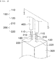
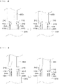
- FIG. 2 is a perspective view of a welding rod inspection apparatus according to a first preferred embodiment of the present invention
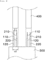
- FIG. 3 is a sectional view of the welding rod inspection apparatus taken along line A-A' of FIG. 2 .
- the welding rod inspection apparatus includes a first measurement unit 100, a second measurement unit 200, and a support die 300.
- two measurement units each of which includes a first measurement unit 100 and a second measurement unit 200, are located side by side, which, however, is merely an example.
- a single measurement unit may be provided, or three or more measurement units may be continuously arranged in a state of being spaced apart from each other by a predetermined distance.
- the first measurement unit 100 includes a first contact portion 110 and a first support shaft 120 configured to support the first contact portion 110.
- the first contact portion 110 is a portion that comes into close contact with a lower end of a welding rod 400 at the time of inspection.
- the first contact portion may be formed in a conical shape having a width gradually decreasing towards a top of each of the first contact portion and the second contact portion.
- a pressure sensor (not shown) configured to measure pressure when the first contact portion 110 comes into close contact with the welding rod 400 is mounted in the first contact portion 110.
- the first support shaft 120 is connected to the support die 300 in a state of being located under the first contact portion 110.
- the first measurement unit 100 which is constituted by the first contact portion 110 and the first support shaft 120, is capable of being moved in a vertical direction by a known driving means (not shown).
- the second measurement unit 200 includes a second contact portion 210 and a second support shaft 220 configured to support the second contact portion 210.
- the second contact portion 210 and the second support shaft 220 are identical in construction to the first contact portion 110 and the first support shaft 120, respectively, and therefore a duplicate description thereof will be omitted.
- the support die 300 is located under the first measurement unit 100 and the second measurement unit 200, and supports the first measurement unit 100 and the second measurement unit 200. Meanwhile, a driving means (not shown) configured to move the first measurement unit and the second measurement unit upwards and downwards in the vertical direction is mounted in the support die.
- the support die 300 is provided therein with a space in which the first measurement unit 100 and the second measurement unit 200 are moved upwards and downwards and the driving means is received.
- the first measurement unit 100 and the second measurement unit 200 located so as to protrude above the support die 300 are spaced apart from each other by a predetermined distance in order to constitute a single measurement unit.
- the distance L1 between the upper ends of the first contact portion 110 and the second contact portion 120, i.e. the ends of the first contact portion and the second contact portion that abut the welding rod 400 to be equal to or less than the diameter L2 of the welding rod such that eccentricity of the welding rod 400, a bending phenomenon of the welding rod, or whether the end surface of the welding rod is deformed can be determined.
- the pressure sensor is mounted in the contact portion; however, the present invention is not limited thereto.
- the pressure sensor may be provided at the support shaft, may be provided between the contact portion and the support shaft, or may be provided at a lower end of the support shaft. That is, the position of the pressure sensor is not particularly restricted as long as it is possible to measure pressure when the welding rod 400 and the measurement unit come into tight contact with each other.
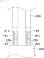
- FIG. 4 is a sectional view of a welding rod inspection apparatus according to a second preferred embodiment of the present invention.
- the welding rod inspection apparatus according to the second embodiment is identical to the welding rod inspection apparatus according to the first embodiment described with reference to FIGS. 2 and 3 except that the shape of each of the first contact portion 110 and the second contact portion 210 is an oval shape that is long up and down, and therefore a description of the same construction will be omitted.
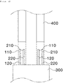
- FIG. 5 is a sectional view of a welding rod inspection apparatus according to a third preferred embodiment of the present invention.
- the welding rod inspection apparatus according to the third embodiment is identical to the welding rod inspection apparatus according to the first embodiment described with reference to FIGS. 2 and 3 except that the shape of each of the first contact portion 110 and the second contact portion 210 is an oval cylindrical shape, and therefore a description of the same construction will be omitted.
- An inspection method of determining whether a welding rod is normal includes a first step of locating the first measurement unit 100 and the second measurement unit 200 at predetermined coordinates, a second step of locating a welding rod vertically above the first measurement unit 100 and the second measurement unit 200, a third step of moving the first measurement unit 100 and the second measurement unit 200 or the welding rod 400 to a predetermined position in a vertical direction, a fourth step of measuring pressures of the first measurement unit 100 and the second measurement unit 200, and a fifth step of determining whether the welding rod 400 is normal based on the result of measurement.
- FIG. 6 is a sectional view showing checking whether a welding rod is eccentric using the welding rod inspection apparatus according to the present invention. A method of checking whether welding rod is eccentric will be described with reference to FIG. 6 . After the first measurement unit 100 and the second measurement unit 200 are located at predetermined coordinates, the first measurement unit 100 and the second measurement unit 200 are moved upwards until the first measurement unit 100 and the second measurement unit 200 come into tight contact with a lower end surface of the welding rod 400.
- the first measurement unit 100 and the second measurement unit 200 are moved for inspection in the state in which the welding rod 400 is stationary.
- the welding rod 400 may be moved downwards for inspection in the state in which the first measurement unit 100 and the second measurement unit 200 are stationary, or the first measurement unit 100, the second measurement unit 200, and the welding rod 400 may be simultaneously moved in the vertical direction for inspection.
- FIG. 7 is a sectional view showing checking a bending phenomenon of a welding rod using the welding rod inspection apparatus according to the present invention
- FIG. 8 is a sectional view showing checking a deformed state of the end surface of a welding rod using the welding rod inspection apparatus according to the present invention.
- a method of checking a bending phenomenon of a welding rod or whether the end surface of a welding rod is deformed will be described with reference to FIGS. 7 and 8 .
- the first measurement unit 100 and the second measurement unit 200 are moved upwards until the first measurement unit 100 and the second measurement unit 200 come into tight contact with a lower end surface of the welding rod 400.
Landscapes
- Physics & Mathematics (AREA)
- General Physics & Mathematics (AREA)
- A Measuring Device Byusing Mechanical Method (AREA)
- Length Measuring Devices With Unspecified Measuring Means (AREA)
Applications Claiming Priority (2)
| Application Number | Priority Date | Filing Date | Title |
|---|---|---|---|
| KR1020200137690A KR102875270B1 (ko) | 2020-10-22 | 2020-10-22 | 용접봉 정상여부를 측정하는 용접봉 검사장치 및 이를 이용한 검사방법 |
| PCT/KR2021/012515 WO2022085951A1 (ko) | 2020-10-22 | 2021-09-14 | 용접봉 정상여부를 측정하는 용접봉 검사장치 및 이를 이용한 검사방법 |
Publications (2)
| Publication Number | Publication Date |
|---|---|
| EP4123260A1 true EP4123260A1 (de) | 2023-01-25 |
| EP4123260A4 EP4123260A4 (de) | 2023-10-25 |
Family
ID=81289975
Family Applications (1)
| Application Number | Title | Priority Date | Filing Date |
|---|---|---|---|
| EP21883023.0A Pending EP4123260A4 (de) | 2020-10-22 | 2021-09-14 | Schweisselektrodeninspektionsvorrichtung zur messung der normalen schweisselektrode und inspektionsverfahren damit |
Country Status (7)
| Country | Link |
|---|---|
| US (1) | US12281894B2 (de) |
| EP (1) | EP4123260A4 (de) |
| JP (1) | JP7501880B2 (de) |
| KR (1) | KR102875270B1 (de) |
| CN (1) | CN115461594B (de) |
| TW (1) | TWI873386B (de) |
| WO (1) | WO2022085951A1 (de) |
Families Citing this family (2)
| Publication number | Priority date | Publication date | Assignee | Title |
|---|---|---|---|---|
| WO2025135556A1 (ko) * | 2023-12-20 | 2025-06-26 | 주식회사 엘지에너지솔루션 | 용접봉 검사 방법과 검사 장치, 및 이를 포함하는 이차전지 제조방법 |
| CN118513633B (zh) * | 2024-07-25 | 2024-10-25 | 河南威猛振动设备股份有限公司 | 一种展臂焊接机器人及其焊条更换装置 |
Family Cites Families (38)
| Publication number | Priority date | Publication date | Assignee | Title |
|---|---|---|---|---|
| KR940008590B1 (ko) | 1991-12-31 | 1994-09-24 | 대우중공업 주식회사 | 아크용접 로보트의 툴(Tool)선 이상 검출처리방법 |
| DE9301457U1 (de) * | 1993-02-03 | 1993-06-09 | Peperkorn, Friedrich, 4520 Melle | Koordinatenmeßgerät |
| US5656126A (en) * | 1996-02-05 | 1997-08-12 | Martinez; Leo | Heat welding accessories |
| AT406461B (de) * | 1997-12-15 | 2000-05-25 | Fronius Schweissmasch | Schweissbrenner |
| JP2000258148A (ja) | 1999-03-12 | 2000-09-22 | Sekisui Chem Co Ltd | 長尺物の端面形状測定装置 |
| JP2000288733A (ja) * | 1999-04-06 | 2000-10-17 | Komatsu Ltd | 溶接ロボット自動原点チェック装置及びそのチェック方法 |
| JP2002005644A (ja) | 2000-06-21 | 2002-01-09 | Nippon Steel Weld Prod & Eng Co Ltd | 被覆アーク溶接棒の偏心検出装置 |
| DE10241069B4 (de) | 2002-09-05 | 2004-07-15 | Aesculap Ag & Co. Kg | Vorrichtung zur Erfassung der Kontur einer Oberfläche |
| US6813843B1 (en) * | 2003-05-07 | 2004-11-09 | The Boeing Company | Tool alignment indicator apparatus and method |
| US20080087097A1 (en) | 2005-02-18 | 2008-04-17 | Sumitomo Heavy Industries, Ltd. | Strain Measuring Device And Fixing Method Of Strain Measuring |
| JP2007167945A (ja) * | 2005-12-26 | 2007-07-05 | Toyota Motor Corp | アーク溶接方法及びアーク溶接機並びにこのアーク溶接機に使用される溶接ワイヤ位置ズレ確認治具 |
| EP2138820B1 (de) * | 2008-06-25 | 2016-09-21 | Sensata Technologies, Inc. | Piezoresistiver Druckmessungsstecker für einen Verbrennungsmotor |
| US7999243B2 (en) * | 2008-09-22 | 2011-08-16 | GM Global Technology Operations LLC | Apparatus and method for determining a dimensional characteristic of an installed weld fastener |
| AT508695B1 (de) * | 2008-11-27 | 2014-02-15 | Fronius Int Gmbh | Kontaktschale zur kontaktierung eines schweissdrahtes in einem schweissbrenner |
| CN102472614B (zh) | 2009-07-31 | 2015-04-01 | Asml控股股份有限公司 | 低压和高压接近式传感器 |
| KR101215991B1 (ko) * | 2010-12-15 | 2012-12-27 | 에이피시스템 주식회사 | 평탄도 검사 장치 및 이를 이용한 평탄도 검사 방법 |
| JP5502014B2 (ja) * | 2011-04-08 | 2014-05-28 | 豊田鉄工株式会社 | 自動溶接ロボットの電極異常検出装置 |
| CN103648703A (zh) * | 2011-07-08 | 2014-03-19 | 焊接机器人公司 | 用于在焊接期间手工焊缝跟踪的系统和方法以及焊接辅助系统 |
| KR101278543B1 (ko) * | 2012-12-04 | 2013-06-25 | 박희만 | 스폿용접건의 팁 정렬상태 검사장치 및 이를 구비한 팁 드레서 |
| ES2622891T3 (es) | 2013-08-01 | 2017-07-07 | Sinterleghe S.R.L. | Dispositivo óptico para detectar la calidad de los electrodos de pistola de soldadura |
| US9589481B2 (en) * | 2014-01-07 | 2017-03-07 | Illinois Tool Works Inc. | Welding software for detection and control of devices and for analysis of data |
| US9757819B2 (en) * | 2014-01-07 | 2017-09-12 | Illinois Tool Works Inc. | Calibration tool and method for a welding system |
| JP6291370B2 (ja) | 2014-07-02 | 2018-03-14 | 株式会社東芝 | 歪検出素子、圧力センサ、マイクロフォン、血圧センサ及びタッチパネル |
| KR101481373B1 (ko) | 2014-10-17 | 2015-01-14 | 이주영 | 스폿용접건의 팁 정렬상태 검사장치 |
| KR101724461B1 (ko) * | 2015-04-17 | 2017-04-07 | 현대자동차 주식회사 | 용접건 정렬상태 측정장치 |
| KR101836081B1 (ko) | 2016-06-07 | 2018-03-09 | 아진산업(주) | 용접팁 직진도 검사장치 |
| EP3511672A4 (de) | 2016-09-09 | 2020-09-09 | Nejilaw Inc. | Sensorstruktur, mit einer sensorstruktur ausgestattete komponente und strukturierungsverfahren für sensorstruktur |
| EP3698911A4 (de) * | 2017-10-17 | 2021-09-01 | LG Electronics Inc. | Schweisssystem und betriebsverfahren dafür |
| EP3477248B1 (de) | 2017-10-26 | 2023-06-07 | Heinrich Georg GmbH Maschinenfabrik | Inspektionssystem und verfahren zur fehleranalyse |
| KR102120414B1 (ko) * | 2017-11-30 | 2020-06-08 | 오성규 | 용접부위 형상과 3d 좌표 측정을 이용한 용접 자동화시스템 및 이를 이용한 용접 방법 |
| KR102389447B1 (ko) | 2018-03-29 | 2022-04-22 | 주식회사 엘지에너지솔루션 | 원통형 배터리 저항 용접 장치 및 이를 이용한 원통형 배터리 저항 용접 방법, 그리고 이를 통해 제작된 원통형 배터리 |
| JP2019195815A (ja) | 2018-05-08 | 2019-11-14 | カイラスインターナショナル株式会社 | 溶接用チップの検査装置及び検査方法 |
| CN109809106A (zh) | 2018-11-28 | 2019-05-28 | 青岛环球输送带有限公司 | 一种沙船专用耐热输送带及其制备工艺 |
| CN109855591B (zh) * | 2019-03-31 | 2025-07-15 | 上海新朋联众汽车零部件有限公司 | 检测弧焊机器人导电嘴及焊枪喷嘴中心点对中度的装置 |
| KR102887063B1 (ko) | 2019-05-31 | 2025-11-17 | 엘지이노텍 주식회사 | 카메라 모듈 |
| CN111578876B (zh) | 2020-05-29 | 2022-03-01 | 英格索兰(中国)工业设备制造有限公司 | 测量杆和三坐标测量机 |
| KR102783416B1 (ko) * | 2020-06-19 | 2025-03-19 | 현대자동차주식회사 | 모재에 형상을 부여하는 방식의 용접 방법 및 이를 위한 모재 |
| JP2024027367A (ja) * | 2022-08-17 | 2024-03-01 | 三菱重工業株式会社 | 肉盛溶接方法 |
-
2020
- 2020-10-22 KR KR1020200137690A patent/KR102875270B1/ko active Active
-
2021
- 2021-09-14 CN CN202180030141.6A patent/CN115461594B/zh active Active
- 2021-09-14 WO PCT/KR2021/012515 patent/WO2022085951A1/ko not_active Ceased
- 2021-09-14 US US17/924,636 patent/US12281894B2/en active Active
- 2021-09-14 EP EP21883023.0A patent/EP4123260A4/de active Pending
- 2021-09-14 JP JP2022571317A patent/JP7501880B2/ja active Active
- 2021-10-06 TW TW110137144A patent/TWI873386B/zh active
Also Published As
| Publication number | Publication date |
|---|---|
| KR102875270B1 (ko) | 2025-10-23 |
| EP4123260A4 (de) | 2023-10-25 |
| TW202229815A (zh) | 2022-08-01 |
| KR20220053342A (ko) | 2022-04-29 |
| WO2022085951A1 (ko) | 2022-04-28 |
| TWI873386B (zh) | 2025-02-21 |
| US20230184532A1 (en) | 2023-06-15 |
| US12281894B2 (en) | 2025-04-22 |
| CN115461594A (zh) | 2022-12-09 |
| JP2023527182A (ja) | 2023-06-27 |
| CN115461594B (zh) | 2025-07-18 |
| JP7501880B2 (ja) | 2024-06-18 |
Similar Documents
| Publication | Publication Date | Title |
|---|---|---|
| KR102909381B1 (ko) | 배터리 모듈 셀 파우치 절연 저항 검사 시스템 | |
| US12281894B2 (en) | Welding rod inspection apparatus for measuring whether welding rod is normal and inspection method using the same | |
| KR102862695B1 (ko) | 전지의 용접 검사장치 및 용접 검사방법 | |
| EP4026651B1 (de) | Schweissqualitätsprüfvorrichtung | |
| EP4098393A1 (de) | Vorrichtung zum biegen und schweissen von elektrodenleitungen und verfahren zum schweissen von elektrodenleitungen damit | |
| KR20220148006A (ko) | 배터리 모듈 정렬도 검사 시스템 및 그 방법 | |
| KR102900762B1 (ko) | 와전류 센서를 이용한 전지 셀의 균열 검사 시스템 | |
| US12298278B2 (en) | Battery cell weld portion inspection apparatus and battery cell weld portion inspection method using the same | |
| CN114859122A (zh) | 电池固定夹具以及具有该电池固定夹具的弱焊接检查装置 | |
| EP4439776A1 (de) | Vorrichtung zur inspektion der verformung von beutelzellen und verfahren zur verformungsinspektion damit | |
| KR102493137B1 (ko) | 배터리 쇼트검사장치 | |
| KR20160112333A (ko) | 다양한 전장 및 두께를 갖는 전지팩들의 검사 장치 | |
| KR102816445B1 (ko) | 와전류를 이용한 전지 셀의 균열 검사 장치 및 방법 | |
| CN108321420A (zh) | 蓄电装置的制造方法、蓄电元件以及蓄电装置 | |
| KR102816454B1 (ko) | 전지 셀의 균열 검사를 위한 와전류 센서 및 이를 이용한 전지 셀의 균열 검사 방법 | |
| CN223038049U (zh) | 电池极板表面多点位导电检测装置和系统 | |
| EP4406675A1 (de) | Nietvorrichtung zur verhinderung des auftretens des nichtvortretens einer befestigung und nietverfahren damit | |
| KR102666323B1 (ko) | 파우치형 이차전지 셀의 단선 검출센서 및 검사시스템을 갖춘 인라인 장치 | |
| CN219757134U (zh) | 一种汽车前轮罩快速检具 | |
| CN220305385U (zh) | 极板导电检测装置和极板导电检测系统 | |
| KR102820968B1 (ko) | 이차 전지를 검사하기 위한 장치 및 방법 | |
| CN217637078U (zh) | 一种穿梭车升降座精度检测装置 | |
| KR102281208B1 (ko) | 배터리 케이스 공차 측정장치 | |
| US11777181B2 (en) | Metal plate for resistance welding and resistance welding method using the same | |
| CN118575328A (zh) | 袋型电池单元变形测试装置以及使用所述袋型电池单元变形测试装置的变形测试方法 |
Legal Events
| Date | Code | Title | Description |
|---|---|---|---|
| STAA | Information on the status of an ep patent application or granted ep patent |
Free format text: STATUS: THE INTERNATIONAL PUBLICATION HAS BEEN MADE |
|
| PUAI | Public reference made under article 153(3) epc to a published international application that has entered the european phase |
Free format text: ORIGINAL CODE: 0009012 |
|
| STAA | Information on the status of an ep patent application or granted ep patent |
Free format text: STATUS: REQUEST FOR EXAMINATION WAS MADE |
|
| 17P | Request for examination filed |
Effective date: 20221019 |
|
| AK | Designated contracting states |
Kind code of ref document: A1 Designated state(s): AL AT BE BG CH CY CZ DE DK EE ES FI FR GB GR HR HU IE IS IT LI LT LU LV MC MK MT NL NO PL PT RO RS SE SI SK SM TR |
|
| A4 | Supplementary search report drawn up and despatched |
Effective date: 20230926 |
|
| RIC1 | Information provided on ipc code assigned before grant |
Ipc: G01B 21/32 20060101ALI20230920BHEP Ipc: B23K 35/10 20060101ALI20230920BHEP Ipc: G01B 21/16 20060101ALI20230920BHEP Ipc: G01B 21/24 20060101AFI20230920BHEP |
|
| DAV | Request for validation of the european patent (deleted) | ||
| DAX | Request for extension of the european patent (deleted) | ||
| STAA | Information on the status of an ep patent application or granted ep patent |
Free format text: STATUS: EXAMINATION IS IN PROGRESS |
|
| 17Q | First examination report despatched |
Effective date: 20250428 |