EP4122713B1 - Befestigbares lichtabschirmungsgehäuse für eine lichtquellenvorrichtung - Google Patents
Befestigbares lichtabschirmungsgehäuse für eine lichtquellenvorrichtung Download PDFInfo
- Publication number
- EP4122713B1 EP4122713B1 EP22196570.0A EP22196570A EP4122713B1 EP 4122713 B1 EP4122713 B1 EP 4122713B1 EP 22196570 A EP22196570 A EP 22196570A EP 4122713 B1 EP4122713 B1 EP 4122713B1
- Authority
- EP
- European Patent Office
- Prior art keywords
- housing
- light
- air
- source device
- space
- Prior art date
- Legal status (The legal status is an assumption and is not a legal conclusion. Google has not performed a legal analysis and makes no representation as to the accuracy of the status listed.)
- Active
Links
Images


Classifications
-
- F—MECHANICAL ENGINEERING; LIGHTING; HEATING; WEAPONS; BLASTING
- F21—LIGHTING
- F21V—FUNCTIONAL FEATURES OR DETAILS OF LIGHTING DEVICES OR SYSTEMS THEREOF; STRUCTURAL COMBINATIONS OF LIGHTING DEVICES WITH OTHER ARTICLES, NOT OTHERWISE PROVIDED FOR
- F21V29/00—Protecting lighting devices from thermal damage; Cooling or heating arrangements specially adapted for lighting devices or systems
- F21V29/50—Cooling arrangements
- F21V29/70—Cooling arrangements characterised by passive heat-dissipating elements, e.g. heat-sinks
- F21V29/74—Cooling arrangements characterised by passive heat-dissipating elements, e.g. heat-sinks with fins or blades
-
- B—PERFORMING OPERATIONS; TRANSPORTING
- B41—PRINTING; LINING MACHINES; TYPEWRITERS; STAMPS
- B41J—TYPEWRITERS; SELECTIVE PRINTING MECHANISMS, i.e. MECHANISMS PRINTING OTHERWISE THAN FROM A FORME; CORRECTION OF TYPOGRAPHICAL ERRORS
- B41J11/00—Devices or arrangements of selective printing mechanisms, e.g. ink-jet printers or thermal printers, for supporting or handling copy material in sheet or web form
- B41J11/0015—Devices or arrangements of selective printing mechanisms, e.g. ink-jet printers or thermal printers, for supporting or handling copy material in sheet or web form for treating before, during or after printing or for uniform coating or laminating the copy material before or after printing
- B41J11/002—Curing or drying the ink on the copy materials, e.g. by heating or irradiating
- B41J11/0021—Curing or drying the ink on the copy materials, e.g. by heating or irradiating using irradiation
- B41J11/00214—Curing or drying the ink on the copy materials, e.g. by heating or irradiating using irradiation using UV radiation
-
- B—PERFORMING OPERATIONS; TRANSPORTING
- B41—PRINTING; LINING MACHINES; TYPEWRITERS; STAMPS
- B41J—TYPEWRITERS; SELECTIVE PRINTING MECHANISMS, i.e. MECHANISMS PRINTING OTHERWISE THAN FROM A FORME; CORRECTION OF TYPOGRAPHICAL ERRORS
- B41J11/00—Devices or arrangements of selective printing mechanisms, e.g. ink-jet printers or thermal printers, for supporting or handling copy material in sheet or web form
- B41J11/0015—Devices or arrangements of selective printing mechanisms, e.g. ink-jet printers or thermal printers, for supporting or handling copy material in sheet or web form for treating before, during or after printing or for uniform coating or laminating the copy material before or after printing
- B41J11/002—Curing or drying the ink on the copy materials, e.g. by heating or irradiating
- B41J11/0021—Curing or drying the ink on the copy materials, e.g. by heating or irradiating using irradiation
- B41J11/00218—Constructional details of the irradiation means, e.g. radiation source attached to reciprocating print head assembly or shutter means provided on the radiation source
-
- F—MECHANICAL ENGINEERING; LIGHTING; HEATING; WEAPONS; BLASTING
- F21—LIGHTING
- F21S—NON-PORTABLE LIGHTING DEVICES; SYSTEMS THEREOF; VEHICLE LIGHTING DEVICES SPECIALLY ADAPTED FOR VEHICLE EXTERIORS
- F21S4/00—Lighting devices or systems using a string or strip of light sources
- F21S4/20—Lighting devices or systems using a string or strip of light sources with light sources held by or within elongate supports
- F21S4/28—Lighting devices or systems using a string or strip of light sources with light sources held by or within elongate supports rigid, e.g. LED bars
-
- F—MECHANICAL ENGINEERING; LIGHTING; HEATING; WEAPONS; BLASTING
- F21—LIGHTING
- F21V—FUNCTIONAL FEATURES OR DETAILS OF LIGHTING DEVICES OR SYSTEMS THEREOF; STRUCTURAL COMBINATIONS OF LIGHTING DEVICES WITH OTHER ARTICLES, NOT OTHERWISE PROVIDED FOR
- F21V15/00—Protecting lighting devices from damage
- F21V15/01—Housings, e.g. material or assembling of housing parts
-
- F—MECHANICAL ENGINEERING; LIGHTING; HEATING; WEAPONS; BLASTING
- F21—LIGHTING
- F21V—FUNCTIONAL FEATURES OR DETAILS OF LIGHTING DEVICES OR SYSTEMS THEREOF; STRUCTURAL COMBINATIONS OF LIGHTING DEVICES WITH OTHER ARTICLES, NOT OTHERWISE PROVIDED FOR
- F21V29/00—Protecting lighting devices from thermal damage; Cooling or heating arrangements specially adapted for lighting devices or systems
- F21V29/50—Cooling arrangements
- F21V29/60—Cooling arrangements characterised by the use of a forced flow of gas, e.g. air
- F21V29/67—Cooling arrangements characterised by the use of a forced flow of gas, e.g. air characterised by the arrangement of fans
- F21V29/677—Cooling arrangements characterised by the use of a forced flow of gas, e.g. air characterised by the arrangement of fans the fans being used for discharging
-
- F—MECHANICAL ENGINEERING; LIGHTING; HEATING; WEAPONS; BLASTING
- F21—LIGHTING
- F21V—FUNCTIONAL FEATURES OR DETAILS OF LIGHTING DEVICES OR SYSTEMS THEREOF; STRUCTURAL COMBINATIONS OF LIGHTING DEVICES WITH OTHER ARTICLES, NOT OTHERWISE PROVIDED FOR
- F21V29/00—Protecting lighting devices from thermal damage; Cooling or heating arrangements specially adapted for lighting devices or systems
- F21V29/50—Cooling arrangements
- F21V29/70—Cooling arrangements characterised by passive heat-dissipating elements, e.g. heat-sinks
- F21V29/74—Cooling arrangements characterised by passive heat-dissipating elements, e.g. heat-sinks with fins or blades
- F21V29/76—Cooling arrangements characterised by passive heat-dissipating elements, e.g. heat-sinks with fins or blades with essentially identical parallel planar fins or blades, e.g. with comb-like cross-section
-
- F—MECHANICAL ENGINEERING; LIGHTING; HEATING; WEAPONS; BLASTING
- F21—LIGHTING
- F21V—FUNCTIONAL FEATURES OR DETAILS OF LIGHTING DEVICES OR SYSTEMS THEREOF; STRUCTURAL COMBINATIONS OF LIGHTING DEVICES WITH OTHER ARTICLES, NOT OTHERWISE PROVIDED FOR
- F21V29/00—Protecting lighting devices from thermal damage; Cooling or heating arrangements specially adapted for lighting devices or systems
- F21V29/50—Cooling arrangements
- F21V29/70—Cooling arrangements characterised by passive heat-dissipating elements, e.g. heat-sinks
- F21V29/83—Cooling arrangements characterised by passive heat-dissipating elements, e.g. heat-sinks the elements having apertures, ducts or channels, e.g. heat radiation holes
-
- B—PERFORMING OPERATIONS; TRANSPORTING
- B41—PRINTING; LINING MACHINES; TYPEWRITERS; STAMPS
- B41J—TYPEWRITERS; SELECTIVE PRINTING MECHANISMS, i.e. MECHANISMS PRINTING OTHERWISE THAN FROM A FORME; CORRECTION OF TYPOGRAPHICAL ERRORS
- B41J2/00—Typewriters or selective printing mechanisms characterised by the printing or marking process for which they are designed
- B41J2/435—Typewriters or selective printing mechanisms characterised by the printing or marking process for which they are designed characterised by selective application of radiation to a printing material or impression-transfer material
- B41J2/447—Typewriters or selective printing mechanisms characterised by the printing or marking process for which they are designed characterised by selective application of radiation to a printing material or impression-transfer material using arrays of radiation sources
- B41J2/45—Typewriters or selective printing mechanisms characterised by the printing or marking process for which they are designed characterised by selective application of radiation to a printing material or impression-transfer material using arrays of radiation sources using light-emitting diode [LED] or laser arrays
-
- F—MECHANICAL ENGINEERING; LIGHTING; HEATING; WEAPONS; BLASTING
- F21—LIGHTING
- F21Y—INDEXING SCHEME ASSOCIATED WITH SUBCLASSES F21K, F21L, F21S and F21V, RELATING TO THE FORM OR THE KIND OF THE LIGHT SOURCES OR OF THE COLOUR OF THE LIGHT EMITTED
- F21Y2103/00—Elongate light sources, e.g. fluorescent tubes
- F21Y2103/10—Elongate light sources, e.g. fluorescent tubes comprising a linear array of point-like light-generating elements
-
- F—MECHANICAL ENGINEERING; LIGHTING; HEATING; WEAPONS; BLASTING
- F21—LIGHTING
- F21Y—INDEXING SCHEME ASSOCIATED WITH SUBCLASSES F21K, F21L, F21S and F21V, RELATING TO THE FORM OR THE KIND OF THE LIGHT SOURCES OR OF THE COLOUR OF THE LIGHT EMITTED
- F21Y2115/00—Light-generating elements of semiconductor light sources
- F21Y2115/10—Light-emitting diodes [LED]
Definitions
- One aspect of the present invention relates to a light source device.
- a light source device including a plurality of light emitting elements which are arranged along a predetermined direction in a housing having a great length along the predetermined direction.
- an intake port and an exhaust port are respectively provided in one end and the other end of the predetermined direction in the housing, to cool the plurality of light emitting elements, in one instance.
- a light emitting element in one end is cooled to a greater extent than a light emitting element in the other end, and thus, light outputs of the plurality of light emitting elements cannot be equalized.
- an intake port is provided in a side surface between the one end and the other end in the housing and an exhaust port is provided in the other end of the housing, to cool the plurality of light emitting elements, in another instance.
- a light emitting element in the other end is cooled to a greater extent than a light emitting element in one end, and thus light outputs of the plurality of light emitting elements cannot be equalized.
- devices described in Japanese Unexamined Patent Publication No. 2011-165509 and Japanese Unexamined Patent Publication No. 2012-074422 are known, for example.
- an LED lighting device described in Japanese Unexamined Patent Publication No. 2011-165509 an LED-equipped substrate which is equipped with a plurality of LEDs is mounted onto a heat dissipation block, and heat of the LEDs is dissipated by the heat dissipation block.
- Japanese Unexamined Patent Publication No. 2011-165509 an LED-equipped substrate which is equipped with a plurality of LEDs is mounted onto a heat dissipation block, and heat of the LEDs is dissipated by the heat dissipation block.
- a first channel through which a refrigerant flows from one end to the other end of the heat dissipation block, and a second channel through which a refrigerant flows from the other end to one end of the heat dissipation block, are provided.
- the plurality of light emitting elements are cooled.
- a plurality of LEDs are mounted onto a heat dissipation member including a channel through which a refrigerant flows along a lengthwise direction.
- a refrigerant is introduced into a channel from a lengthwise center, and the foregoing channel includes a channel through which a refrigerant flows from a lengthwise center to one end, and a channel through which a refrigerant flows from a lengthwise center to the other end.
- a light source device it is required to equalize temperatures of a plurality of light emitting elements so that respective light outputs of the plurality of light emitting elements are kept constant.
- the above-described conventional techniques still have room for improvement from a viewpoint of reducing the number of components or simplifying a configuration.
- positions and the numbers of intake ports and exhaust ports of the light source devices are limited in order to reduce an influence of air upon an illuminated object (a printed material on which UV-light-curing ink deposits), in some cases.
- KR101647501B1 describes an irradiation device with a top housing hinged to a lower housing. The substrate is transported in a passage between the two housing parts.
- a light source device is described in appended claim 1. Other aspects of the invention are described in the dependent claims.
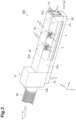
- a light source device 100 is a high-power air-cooled LED light source for use in printing, for example.
- the light source device 100 can be used as a light source unit which has a great length and is mounted onto a UV printing apparatus (UV printer), for example.
- the light source device 100 emits light such as ultraviolet light, and dries ink, for example.
- the light source device 100 includes a housing 10, a plurality of LED substrates 30, a supporting block 40, a plurality of heat sinks 50, a pair of driving circuits 60, a radial-flow fan 70, and a light shielding case 80.
- a lengthwise direction (predetermined direction) of the housing 10 is an "X direction”
- a direction in which light is emitted from LED elements 31 of the LED substrates 30, being perpendicular to an X direction is a "Y direction”
- a widthwise direction of the light source device 100, being orthogonal to an X direction and a Y direction is a "Z direction”.
- a side toward which the LED elements 31 emit light is a "lower side” and a side opposite thereto is an "upper side”.
- the housing 10 is in a form of a rectangular box having a great length along an X direction.
- the housing 10 is formed of metal.
- the housing 10 holds the LED substrates 30, the supporting block 40, the heat sinks 50, and the driving circuits 60.
- a first intake port 11 through which air is sucked into the housing 10 from the outside is provided.
- the first intake port 11 is formed so as to open outward in an X direction.
- a grip unit 12 for gripping the housing 10 is provided in the one end surface 10a.
- an exhaust port 13 through which air is discharged to the outside from the housing 10 is provided.
- the exhaust port 13 is connected with a blower 91 which sucks air, via a pipe 92 having bellows. Accordingly, in the housing 10, a pressure of air on one side in an X direction is higher than that on the other side, and air flows from one side to the other side in an X direction.
- one side in an X direction will be also referred to as an "upstream side”
- the other side in an X direction will be also referred to as a "downstream side".
- the housing 10 includes a body section 15 and a downstream section 25 located downstream of the body section 15.
- An outline of the body section 15 takes a shape of a rectangular parallelepiped having a great length along an X direction.
- An end surface on an upstream side of the body section 15 corresponds to the above-described one end surface 10a.
- the LED substrates 30, the supporting block 40, and the heat sinks 50 are placed in the body section 15.
- a communication port 16 which communicates with a later-described light-shielding-case exhaust port 82 of the light shielding case 80, is formed.
- a lid unit 17 in which a plurality of slits are formed is attached to the communication port 16.
- a buffer unit 19 serving as a buffer space for buffering an air flow is provided.
- the body section 15 includes a lower sidewall unit 20, an upper sidewall unit 21, and a pair of sidewall units 22 and 23 which are continuous with those sidewall units 20 and 21 and are opposite to each other along a Z direction.
- a light emission window 18 which allows light provided from the LED substrates 30 to pass therethrough is provided.
- Each of the upper sidewall unit 21 and the pair of sidewall units 22 and 23 which are opposite to each other along a Z direction is configured to have a double-wall structure.
- the sidewall unit 21 includes an outer sidewall 21o and an inner sidewall 21i.
- the sidewall unit 22 includes an outer sidewall 22o and an inner sidewall 22i.
- the sidewall unit 23 includes an outer sidewall 23o and an inner sidewall 23i.
- Each of the outer sidewalls 21o, 22o, and 23o is a flat-plate-shaped wall member which forms a periphery of the body section 15 (between the first intake port 11 and the exhaust port 13).
- the outer sidewall 21o is provided orthogonally to, and continuously with, the outer sidewalls 22o and 23o.
- the inner sidewalls 21i, 22i, and 23i are flat-plate-shaped wall members which are placed inwardly with respect to the outer sidewalls 21o, 22o, and 23o, respectively.
- the inner sidewall 21i is provided orthogonally to, and continuously with, the inner sidewalls 22i and 23i.
- the inner sidewalls 21i, 22i, and 23i extend along an X direction from a position located downstream of the first intake port 11 by a predetermined distance, to the buffer unit 19. Lower ends of the inner sidewalls 22i and 23i are positioned in the neighborhood of centers of a Y direction in the outer sidewalls 22o and 23o.
- An inter-wall space 24 in which air sucked through the first intake port 11 and the communication port 16 is allowed to flow along an X direction is formed between the outer sidewalls 21o, 22o, and 23o and the inner sidewalls 21i, 22i, and 23i, respectively.
- the inter-wall space 24 has an inverted-U-shaped longitudinal section in a state shown in FIG. 5 . Clearances between the outer sidewalls 22o and 23o and the inner sidewalls 22i and 23i are enclosed by lower ends of the inner sidewalls 22i and 23i. In such the inter-wall space 24, portions on an upstream side and a downstream side communicate with the housing 10, and a lower end is blocked.
- An outline of the downstream section 25 takes a shape of a rectangular parallelepiped of which upper portion protrudes over the body section 15.
- the downstream section 25 is provided continuously with the body section 15.
- An end surface of the downstream section 25 on a downstream side corresponds to the above-described other end surface 10b.
- the downstream section 25 is partitioned into a wire holding space 27 and a ventilation space 28 by a partition plate 26 in a shape of a flat plate extending along an X-Z plane.
- the wire holding space 27 is a space above the partition plate 26 in the downstream section 25, and is defined (demarcated) in an upper portion within the downstream section 25.In the wire holding space 27, a wire C1 is collectively held.
- the ventilation space 28 is a space in which air flows, and communicates with the body section 15 and the exhaust port 13.
- the ventilation space 28 is a space below the partition plate 26 in the downstream section 25. In the ventilation space 28, the pair of driving circuits 60 are placed.
- the LED substrates 30 include substrates each of which forms a predetermined circuit and has a shape of a rectangular plate, and the LED elements 31 serving as light emitting elements which are arranged side by side with predetermined pitches along an X direction and a Y direction on those substrates.
- the LED elements 31 emit light such as ultraviolet light downward.
- the LED substrates 30 are arranged side by side along an X direction on a lower surface of the supporting block 40. Accordingly, several to several hundreds of LED elements 31 are arranged along at least an X direction in the housing 10.
- Light emitted from each of the LED elements 31 of the plurality of LED substrates 30 is irradiated, via the light emission window 18 of the housing 10, to an illuminated object which passes through a later-described passage area R.
- a printed material on which light-(UV-light-) curing ink deposits is cited, for example.
- the supporting block 40 is formed of metal and is placed on a lower side in the body section 15 of the housing 10.
- the plurality of LED substrates 30 are arranged side by side along an X direction on a lower surface of the supporting block 40.
- the plurality of heat sinks 50 are arranged side by side along an X direction.
- Notches 41 each of which is a portion cut out in a rectangular shape in a longitudinal section are formed to extend along an X direction, on lower sides of opposite ends of a Z direction in the supporting block 40 (refer to FIG. 5 ).
- the notches 41 in collaboration with the sidewall unit 20 of the housing 10, form lower spaces 42. In other words, the lower spaces 42 are defined by the notches 41 and the sidewall unit 20.
- the lower space 42 extends from an upstream portion of the body section 15 to a position ahead of the buffer unit 19 (a position located upstream of the buffer unit 19) along an X direction.
- the lower space 42 is partitioned into an upper portion and a lower portion by a partition plate 43. Accordingly, in the lower space 42, a first lower space 44 and a second lower space 45 above the first lower space 44 are formed.
- the first lower space 44 mainly serves as a space in which air sucked through the first intake port 11 and the communication port 16 is allowed to flow along an X direction.
- the first lower space 44 allows air to flow along an inner surface of the sidewall unit 20 of the housing 10, to thereby suppress temperature rise of the sidewall unit 20.
- the second lower space 45 mainly serves as a space in which a wire C2 is collectively held.
- the heat sinks 50 are heat dissipation members which are thermally connected with the LED elements 31 of the LED substrates 30.
- the plurality of (three in this embodiment) heat sinks 50 are placed on an upper surface of the supporting block 40, so as to be arranged at predetermined intervals along an X direction.
- the heat sink 50 includes a base 51 and a plurality of heat dissipation fins 52.
- the base 51 takes a shape of a rectangular plate.
- the base 51 is connected with an upper surface of the supporting block 40. Accordingly, the base 51 is thermally coupled to the LED elements 31 of the LED substrates 30 via the supporting block 40.
- the heat dissipation fin 52 takes a shape of a flat plate having a width along a Z direction and a great length along an X direction.
- the heat dissipation fins 52 are arranged so as to be stacked at some intervals along a Z direction.
- the heat dissipation fins 52 are erected on the base 51.
- the radial-flow fan 70 is fixed to a lower surface of the downstream section 25 of the housing 10.
- the radial-flow fan 70 sucks air from a lower side along a Y direction and feeds the air under pressure to one side of an X direction (an upstream side of air in the housing 10).
- the light shielding case 80 is in a form of a rectangular box which has a great length along an X direction and is flattened along a Y direction.
- the light shielding case 80 is formed of metal.
- the light shielding case 80 is removably attached on a lower side in the body section 15 of the housing 10, and protects the light emission window 18 of the body section 15 from light.
- the light shielding case 80 is inserted into an air-outlet side of the radial-flow fan 70, and the inside of the light shielding case 80 communicates with an air-outlet side of the radial-flow fan 70.
- a groove 81 which defines the passage area R is formed in an upper surface of the light shielding case 80.
- the passage area R is an area where an illuminated object passes along a Z direction.
- a bottom surface of the groove 81 faces the light emission window 18.
- the light-shielding-case exhaust port 82 communicates with the communication port 16 of the housing 10 while the light shielding case 80 is attached to the housing 10.
- air which is sucked and fed under pressure by the radial-flow fan 70 flows from the other side to one side in an X direction (in a direction reverse to a direction of an air flow in the housing 10) in the light shielding case 80. Accordingly, a bottom surface of the groove 81 of which temperature is increased by light which is provided through the light emission window 18 and falls on the bottom surface, is cooled.
- the air flows into an upstream portion of the housing 10 through the light-shielding-case exhaust port 82 via the communication port 16, and merges with air sucked through the first intake port 11. As a result of this, the air sucked through the first intake port 11 flows from one side to the other side in an X direction, together with the air provided from the light shielding case 80.
- a space 1 of which downstream side (the other side in an X direction) faces the heat sinks 50 is formed in the housing 10.
- upstream sides of the heat dissipation fins 52 of the heat sinks 50 face the space 1.
- the heat dissipation fins 52 are placed downstream of the space 1.
- the space 1 is a place where the heat dissipation fins 52 are not provided in the housing 10.
- the space 1 has a certain volume or higher.
- the space 1 is a vacant place in the housing 10.
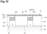
- the space 1 is formed between a pair of adjacent heat sinks 50.
- the space 1 is defined by the notches 53 formed in the respective heat dissipation fins 52 of a pair of adjacent heat sinks 50. More specifically, the space 1 is defined by the respective notches 53 of a pair of adjacent heat sinks 50 and the inner sidewalls 21i, 22i, and 23i, and takes a shape of a rectangular parallelepiped.
- a plurality of (two in this embodiment) second intake ports 2 through which air is sucked from the outside into the space 1 are provided in each of the respective side surfaces 22a and 23a of the pair of sidewall units 22 and 23 in the body section 15. That is, the plurality of second intake ports 2 which connect the space 1 directly to the outside are formed in each of the side surfaces 22a and 23a between the first intake port 11 and the exhaust port 13 in the housing 10.
- the second intake port 2 opens in a Z direction.
- the second intake port 2 includes an outer lid in which a plurality of slits are formed.
- a filter 3 formed of urethane or the like, for example, is attached to the second intake port 2.
- the second intake port 2 is provided in a position where the second intake port 2 overlaps the space 1 when seen from a Z direction.
- the space 1 is positioned in the neighborhood of (around) the second intake ports 2.
- the second intake port 2 which is formed in the side surface 22a and the second intake port 2 which is formed in the side surface 23a face each other along a Z direction.
- the second intake ports 2 are provided in an upper end (that is, an end spaced apart from an illuminated object) of each of the side surfaces 22a and 23a.
- the second intake ports 2 are provided so as not to communicate with the inter-wall space 24 while communicating with the space 1.
- the second intake port 2 includes a through hole which penetrates the outer sidewall 22o and the inner sidewall 22i, and the through hole is closed to the outer sidewall 22o and the inner sidewall 22i.
- the second intake port 2 penetrates the inter-wall space 24 until it reaches the space 1 while keeping itself from communicating with the inter-wall space 24.
- a cover 93 with which the passage area R is covered is attached to a lower end of each of the side surfaces 22a and 23a of the housing 10.
- the cover 93 is a plate member having a width along a Z direction and a great length along an X direction. The cover 93 protects the passage area R from light.
- temperature rise of the LED elements 31 which are provided on a side close to the exhaust port 13 and are easily subjected to temperature rise can be effectively suppressed.
- a temperature gradient among the plurality of LED elements 31 can be reduced, and a difference in temperature between the LED element 31 in the neighborhood of the first intake port 11 and the LED element 31 in the neighborhood of the exhaust port 13 can be reduced, so that temperatures of the plurality of LED elements 31 can be equalized.
- An efficiency of cooling the light source device 100 as a whole can be increased, which makes it possible to miniaturize the device.
- An illuminance gradient among the plurality of LED elements 31 is reduced, so that a difference in illuminance between the LED element 31 in the neighborhood of the first intake port 11 and the LED element 31 in the neighborhood of the exhaust port 13 can be reduced.
- the space 1 is defined by the notches 53 formed in the heat dissipation fins 52. Because of such a configuration of the space 1, it is possible to effectively achieve a technique in which fresh air is sucked from the outside via the second intake ports 2 and is allowed to flow among the heat dissipation fins 52.
- the space 1 is formed between a pair of adjacent heat sinks 50. In this situation, in a case where the plurality of heat sinks 50 are placed, the space 1 can be efficiently formed.
- the space 1 is defined by the notches 53 formed in the respective heat dissipation fins 52 of a pair of adjacent heat sinks 50. Because of such a configuration of the space 1, in a case where the plurality of heat sinks 50 are placed, it is possible to effectively achieve a technique in which fresh air is sucked from the outside via the second intake ports 2 and is allowed to flow among the heat dissipation fins 52.
- the second intake ports 2 are provided in respective ends on an upper side spaced apart from an illuminated object in the side surfaces 22a and 23a. In this situation, mist or the like which is possibly produced from an illuminated object can be prevented from being sucked into the housing 10 via the second intake ports 2.
- each of the sidewall units 21, 22, and 23 of the housing 10 has a double-wall structure, and the inter-wall space 24 in which air sucked through the first intake port 11 is allowed to flow along an X direction is formed.
- the second intake ports 2 are provided so as not to communicate with the inter-wall space 24 while communicating with the space 1. Accordingly, air sucked through the first intake port 11 is allowed to flow in the inter-wall space 24, and so it is possible to surely allowing outside fresh air sucked through the second intake ports 2 to flow into not the inter-wall space 24, but the space 1, and then, among the heat dissipation fins 52, while suppressing temperature rise of the sidewall units 21, 22, and 23 of the housing 10.
- FIG. 7 is a perspective view for showing a simulation result of an air flow around the second intake ports 2.
- an air flow is shown by stream lines.
- the simulation result in FIG. 7 indicates that fresh air which is sucked into the space 1 in the housing 10 via the second intake ports 2 can be surely allowed to flow among the heat dissipation fins 52 on a downstream side.
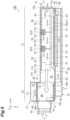
- FIG. 8 is a section view for showing a simulation result of temperature distribution in the housing 10.
- a level of a temperature is shown by a color gradation, and a darker color means a lower temperature.
- a section in FIG. 8 corresponds to a section in FIG. 4 except that the buffer unit 19 and the radial-flow fan 70 are omitted.
- the simulation result in FIG. 8 indicates that temperature rise of the LED element 31 which is provided on a side close to the exhaust port 13 and is easily subjected to temperature rise is suppressed and a temperature gradient among the plurality of LED elements 31 is reduced, so that temperatures of the plurality of LED elements 31 can be equalized.
- a temperature of the light shielding case 80 may possibly be increased to approximately 200 °C, for example, when light emitted via the light emission window 18 falls on the light shielding case 80.
- a temperature of the sidewall unit 20 on a lower side in the housing 10 may possibly be increased under the influence of heat of the light shielding case 80.
- the lower space 42 (the first lower space 44) in which air is allowed to flow along an inner surface of the sidewall unit 20 of the housing 10 is provided. This can suppress temperature rise of the sidewall unit 20.
- the filter 3 is attached to the second intake port 2. Accordingly, dust can be prevented from entering into the housing 10 via the second intake port 2.
- the driving circuits 60 are placed downstream of the LED substrates 30 by a predetermined distance or larger along an X direction. More specifically, the driving circuits 60 are located downstream of the LED substrates 30 by some distance with the buffer unit 19 being interposed therebetween, and are provided in an end on a downstream side in the housing 10 in this embodiment. Accordingly, it is possible to prevent heat of the driving circuits 60 from adversely affecting cooling of the LED elements 31.
- the driving circuits 60 are cooled by air used for cooling the LED elements 31, and thus, an efficiency of cooling of the light source device 100 as a whole can be increased.
- the driving circuits 60 can be cooled by air of which flow is buffered by the buffer unit 19.
- the light source device 100 includes the pair of driving circuits 60.
- the pair of driving circuits 60 are placed in such a manner that the respective circuit heat sinks 61 do not overlap each other along an X direction. This configuration allows heat of the respective circuit heat sinks 61 to be effectively dissipated by air flowing along an X direction.
- the downstream section 25 of the housing 10 is partitioned into the wire holding space 27 and the ventilation space 28 by the partition plate 26. Accordingly, a space in which the wire C1 is held and a space in which air flows are separated from each other, so that it is possible to prevent an air flow from becoming turbulent due to presence of the wire C1.
- the light source device 100 includes the light shielding case 80. With the light shielding case 80, it is possible to shut out light emitted via the light emission window 18 while forming the passage area R where an illuminated object passes or is placed.
- each of the heat dissipation fins 52 may be formed in a shape of a rectangular plate in which the notch 53 (refer to FIG. 4 ) is not provided, and the space 1 may be formed between the plurality of heat sinks 50.
- Each of the heat sinks 50 may include a heat pipe in the above-described embodiment.
- a third intake port through which air is sucked into the buffer unit 19 from the outside may be further included in a position where the third intake port faces the buffer unit 19 in a side surface between the first intake port 11 and the exhaust port 13 of the housing 10.
- the manner in which the LED substrates 30 and the LED elements 31 are arranged is not limited to any specific manner, and it will be sufficient if the plurality of LED elements 31 are arranged along at least an X direction.
- a light emitting element is not limited to the LED element 31, and the other known light emitting element may be used.
- a light source device which can equalize temperatures of a plurality of light emitting elements can be provided.
Landscapes
- Engineering & Computer Science (AREA)
- General Engineering & Computer Science (AREA)
- Health & Medical Sciences (AREA)
- General Health & Medical Sciences (AREA)
- Toxicology (AREA)
- Cooling Or The Like Of Electrical Apparatus (AREA)
- Arrangement Of Elements, Cooling, Sealing, Or The Like Of Lighting Devices (AREA)
- Supply, Installation And Extraction Of Printed Sheets Or Plates (AREA)
- Non-Portable Lighting Devices Or Systems Thereof (AREA)
- Led Device Packages (AREA)
Claims (6)
- Lichtquellen-Vorrichtung, die umfasst:ein Gehäuse (10), das so ausgeführt ist, dass es eine große Länge in einer vorgegebenen Richtung (X) hat;eine Vielzahl lichtemittierender Elemente (31), die in dem Gehäuse (10) positioniert und in wenigstens der vorgegebenen Richtung (X) angeordnet sind;ein oder mehrere Wärmeableitelement/e (50), das/die in dem Gehäuse (10) angeordnet und thermisch mit den lichtemittierenden Elementen (31) verbunden sind; sowie eine Licht abschirmende Verkleidung (80), wobeieine erste Einlassöffnung (11), über die Luft von außen in das Gehäuse (10) eingesaugt wird, in einem Ende (10a) an einer Seite des Gehäuses (10) in der vorgegebenen Richtung (X) vorhanden ist,eine Auslassöffnung (13), über die Luft nach außen aus dem Gehäuse (10) abgeleitet wird, in einem anderen Ende (10b) an einer anderen Seite des Gehäuses (10) in der vorgegebenen Richtung (X) vorhanden ist,die Licht abschirmende Verkleidung (80) abnehmbar an dem Gehäuse (10) angebracht ist,die Licht abschirmende Verkleidung (80) so ausgeführt ist, dass sie von der Lichtquellen-Vorrichtung (100) emittiertes Licht abhält,das Gehäuse (10) mit einem Lichtemissions-Fenster (18) versehen ist, das so ausgeführt ist, dass es Licht von den lichtemittierenden Elementen (31) durchlässt,die Licht abschirmende Verkleidung (80) an dem Gehäuse (10) so angebracht ist, dass sie Licht von dem Lichtemission-Fenster (18) abschirmt, undeine Fläche der Licht abschirmenden Verkleidung (80) mit einem Durchlassbereich (9) versehen ist, der Durchlass eines beleuchteten Objektes in einer Richtung senkrecht zu der vorgegebenen Richtung (X) zulässt.
- Lichtquellen-Vorrichtung nach Anspruch 1, wobeidie Licht abschirmende Verkleidung (80) in eine Luftauslass-Seite eines Zentrifugallüfters (70) eingesetzt ist und eine Innenseite der Licht abschirmenden Verkleidung (80) mit einer Luftauslass-Seite des Zentrifugallüfters (70) in Verbindung steht, undim Inneren der Licht abschirmenden Verkleidung (80) die von dem Zentrifugallüfter (70) angesaugt und unter Druck zugeführte Luft in einer Richtung entgegengesetzt zu einem Luftstrom in dem Gehäuse (10) strömt, und die Seite des Lichtemissions-Fensters (18) der Licht abschirmenden Verkleidung (80) durch die Luft gekühlt wird.
- Lichtquellen-Vorrichtung nach Anspruch 2, wobei
die Luft über eine Auslassöffnung (82) der Licht abschirmenden Verkleidung in einen stromauf liegenden Abschnitt des Gehäuses (10) einströmt und sich mit der über die erste Einlassöffnung (11) angesaugten Luft vermischt. - Lichtquellen-Vorrichtung nach Anspruch 1, wobeiein Raum (1), in dem die andere Seite in der vorgegebenen Richtung (X) dem Wärmeableitelement (50) zugewandt ist, in dem Gehäuse (10) ausgebildet ist, undeine zweite Einlassöffnung (2), über die Luft von außen in den Raum (1) eingesaugt wird, in einer Seitenfläche zwischen der ersten Einlassöffnung (11) und der Auslassöffnung (13) in dem Gehäuse (10) vorhanden ist.
- Lichtquellen-Vorrichtung nach Anspruch 4, wobeidie zweite Einlassöffnung (2) in dem Gehäuse (10) an einer Seite vorhanden ist, die der Stelle gegenüberliegt, von der die lichtemittierenden Elemente (31) das Licht emittieren, undein Raum (1), in den die zweite Einlassöffnung (2) gerichtet ist, ein Teil des Bereiches ist, in dem die Wärmeableitelemente (50) nicht vorhanden sind.
- Lichtquellen-Vorrichtung nach Anspruch 5, wobeidas Gehäuse (10) eine äußere Seitenwand (22o, 23o) zwischen der ersten Einlassöffnung (11) und der Auslassöffnung (13) sowie eine innere Seitenwand (22i, 23i) einschließt, die in Bezug auf die äußere Seitenwand (22o,23o) nach innen gerichtet angeordnet ist,ein Raum (24) zwischen Wänden, der zulässt, dass über die erste Einlassöffnung (11) angesaugte Luft in der vorgegebenen Richtung (X) strömt, zwischen der äußeren Seitenwand und der inneren Seitenwand (22i, 23i) in dem Gehäuse (10) ausgebildet ist, unddie zweite Einlassöffnung (2) so eingerichtet ist, dass sie nicht mit dem Raum (24) zwischen Wänden in Verbindung steht, während sie mit dem Raum (1) in Verbindung steht.
Applications Claiming Priority (2)
| Application Number | Priority Date | Filing Date | Title |
|---|---|---|---|
| JP2017182473A JP7058095B2 (ja) | 2017-09-22 | 2017-09-22 | 光源装置 |
| EP18195907.3A EP3460322B1 (de) | 2017-09-22 | 2018-09-21 | Leuchtevorrichtung |
Related Parent Applications (2)
| Application Number | Title | Priority Date | Filing Date |
|---|---|---|---|
| EP18195907.3A Division-Into EP3460322B1 (de) | 2017-09-22 | 2018-09-21 | Leuchtevorrichtung |
| EP18195907.3A Division EP3460322B1 (de) | 2017-09-22 | 2018-09-21 | Leuchtevorrichtung |
Publications (2)
| Publication Number | Publication Date |
|---|---|
| EP4122713A1 EP4122713A1 (de) | 2023-01-25 |
| EP4122713B1 true EP4122713B1 (de) | 2025-05-21 |
Family
ID=63678467
Family Applications (2)
| Application Number | Title | Priority Date | Filing Date |
|---|---|---|---|
| EP18195907.3A Active EP3460322B1 (de) | 2017-09-22 | 2018-09-21 | Leuchtevorrichtung |
| EP22196570.0A Active EP4122713B1 (de) | 2017-09-22 | 2018-09-21 | Befestigbares lichtabschirmungsgehäuse für eine lichtquellenvorrichtung |
Family Applications Before (1)
| Application Number | Title | Priority Date | Filing Date |
|---|---|---|---|
| EP18195907.3A Active EP3460322B1 (de) | 2017-09-22 | 2018-09-21 | Leuchtevorrichtung |
Country Status (4)
| Country | Link |
|---|---|
| US (2) | US10895376B2 (de) |
| EP (2) | EP3460322B1 (de) |
| JP (3) | JP7058095B2 (de) |
| ES (2) | ES2934793T3 (de) |
Families Citing this family (4)
| Publication number | Priority date | Publication date | Assignee | Title |
|---|---|---|---|---|
| JP6832910B2 (ja) * | 2018-12-24 | 2021-02-24 | Hoya株式会社 | 光照射装置 |
| CN112413512B (zh) * | 2020-11-24 | 2021-06-29 | 烟台旭泰新能源科技有限公司 | 一种太阳能除尘路灯 |
| JP7542428B2 (ja) | 2020-12-24 | 2024-08-30 | 浜松ホトニクス株式会社 | ヒートシンク、活性エネルギ照射装置及び活性エネルギ照射システム |
| JP7542429B2 (ja) * | 2020-12-24 | 2024-08-30 | 浜松ホトニクス株式会社 | 活性エネルギ照射装置及び活性エネルギ照射システム |
Family Cites Families (28)
| Publication number | Priority date | Publication date | Assignee | Title |
|---|---|---|---|---|
| JPH03278831A (ja) * | 1990-03-29 | 1991-12-10 | Toshiba Lighting & Technol Corp | 紫外線照射装置 |
| JP2002292825A (ja) * | 2001-03-30 | 2002-10-09 | Iwasaki Electric Co Ltd | 紫外線照射装置 |
| JP3104468U (ja) | 2004-04-06 | 2004-09-16 | 浩▲しん▼股▲ふん▼有限公司 | 冷却装置の導風装置 |
| JP2006259290A (ja) | 2005-03-17 | 2006-09-28 | Casio Comput Co Ltd | 光源装置及びそれを備えたプロジェクタ |
| DE102005045203B4 (de) * | 2005-09-21 | 2009-08-20 | Uviterno Ag | Modulare Bestrahlungsvorrichtung |
| US7547123B2 (en) * | 2005-09-26 | 2009-06-16 | Advanced Illumination, Inc. | High efficiency, compact, modular forced air cooling system for high intensity LED light source |
| US7338186B1 (en) * | 2006-08-30 | 2008-03-04 | Chaun-Choung Technology Corp. | Assembled structure of large-sized LED lamp |
| WO2008037940A1 (en) * | 2006-09-26 | 2008-04-03 | Ghollam Tahmosybayat | Lamp assembly |
| TW201040453A (en) * | 2009-05-08 | 2010-11-16 | Foxconn Tech Co Ltd | LED lamp with a heat dissipation device |
| US8256927B2 (en) | 2009-09-14 | 2012-09-04 | Leotek Electronics Corporation | Illumination device |
| JP2011165509A (ja) | 2010-02-10 | 2011-08-25 | Moritex Corp | Led照明装置 |
| US8993983B2 (en) * | 2010-05-13 | 2015-03-31 | Nail Alliance Llc | UV LED curing apparatus with improved housing and switch controller |
| KR101216084B1 (ko) | 2010-06-23 | 2012-12-26 | 엘지전자 주식회사 | 조명장치 및 모듈식 조명장치 |
| JP2012024993A (ja) | 2010-07-21 | 2012-02-09 | Nk Works Kk | Led光照射装置及び印刷装置 |
| JPWO2012014516A1 (ja) * | 2010-07-30 | 2013-09-12 | Nkワークス株式会社 | Led発光装置 |
| JP5677795B2 (ja) | 2010-09-27 | 2015-02-25 | パナソニック デバイスSunx株式会社 | Ledユニット |
| US8864332B2 (en) * | 2012-03-14 | 2014-10-21 | Light Emitting Design, Inc. | Passive cooling lighting fixture |
| JP2013215647A (ja) | 2012-04-05 | 2013-10-24 | Gs Yuasa Corp | 紫外線照射装置 |
| KR101228757B1 (ko) * | 2012-08-17 | 2013-01-31 | 주식회사 비솔 | 이중 냉각 구조를 갖는 led 조명장치 |
| US9404648B2 (en) * | 2014-01-15 | 2016-08-02 | Chilled Tech, Llc | LED light with cooling system |
| JP6041158B2 (ja) * | 2014-02-28 | 2016-12-07 | 岩崎電気株式会社 | Ledランプ |
| JP6254035B2 (ja) | 2014-03-31 | 2017-12-27 | Hoya Candeo Optronics株式会社 | 光照射装置 |
| CA2916070C (en) * | 2014-12-19 | 2021-10-26 | Nextlight, LLC | Led grow light |
| US10145551B2 (en) | 2015-04-15 | 2018-12-04 | Titan LED, Inc. | LED lamp with active chamber cooling |
| KR101647501B1 (ko) * | 2015-11-20 | 2016-08-10 | 경일전산폼(주) | 자외선 조사장치를 가지는 병렬 uv 옵셋인쇄장치 |
| JP6294898B2 (ja) * | 2016-01-15 | 2018-03-14 | Hoya Candeo Optronics株式会社 | 光照射装置 |
| CN106004083B (zh) * | 2016-05-26 | 2017-12-15 | 北京印刷学院 | 标签印刷机的反光倍增紫外线固化装置 |
| US10295168B1 (en) * | 2017-11-03 | 2019-05-21 | Aluminis, LLC | LED light fixture with inter-LED flow-through cooling |
-
2017
- 2017-09-22 JP JP2017182473A patent/JP7058095B2/ja active Active
-
2018
- 2018-09-20 US US16/136,554 patent/US10895376B2/en active Active
- 2018-09-21 EP EP18195907.3A patent/EP3460322B1/de active Active
- 2018-09-21 EP EP22196570.0A patent/EP4122713B1/de active Active
- 2018-09-21 ES ES18195907T patent/ES2934793T3/es active Active
- 2018-09-21 ES ES22196570T patent/ES3034288T3/es active Active
-
2020
- 2020-12-09 US US17/116,213 patent/US11204160B2/en active Active
-
2022
- 2022-04-11 JP JP2022065191A patent/JP7529716B2/ja active Active
-
2024
- 2024-04-12 JP JP2024064636A patent/JP7656115B2/ja active Active
Also Published As
| Publication number | Publication date |
|---|---|
| US20210088207A1 (en) | 2021-03-25 |
| JP2019057471A (ja) | 2019-04-11 |
| US20190093872A1 (en) | 2019-03-28 |
| EP3460322B1 (de) | 2022-11-30 |
| EP3460322A1 (de) | 2019-03-27 |
| EP4122713A1 (de) | 2023-01-25 |
| ES3034288T3 (en) | 2025-08-14 |
| JP2024074991A (ja) | 2024-05-31 |
| ES2934793T3 (es) | 2023-02-27 |
| JP7529716B2 (ja) | 2024-08-06 |
| JP7058095B2 (ja) | 2022-04-21 |
| JP7656115B2 (ja) | 2025-04-02 |
| US10895376B2 (en) | 2021-01-19 |
| US11204160B2 (en) | 2021-12-21 |
| JP2022088679A (ja) | 2022-06-14 |
Similar Documents
| Publication | Publication Date | Title |
|---|---|---|
| US11204160B2 (en) | Light source device | |
| US20100073872A1 (en) | Air-cooling of electronics cards | |
| US8622577B2 (en) | Lighting device with air circulation means | |
| JP6349098B2 (ja) | 紫外線照射ヘッド及び紫外線照射装置 | |
| TWI627072B (zh) | Light irradiation device | |
| JP6862803B2 (ja) | 照射装置 | |
| KR20210103545A (ko) | 광조사 장치 및 인쇄 장치 | |
| US20080019125A1 (en) | Backlight module | |
| WO2016042974A1 (ja) | 光照射装置 | |
| EP4250351A1 (de) | Kühlkörper, aktivenergiebestrahlungsvorrichtung und aktivenergiebestrahlungssystem | |
| US10260725B2 (en) | Light emitting device | |
| US12529474B2 (en) | Electronics housing assembly with improved heat dissipation | |
| CN110088528B (zh) | 光照射装置 | |
| US12409667B2 (en) | Active energy irradiation device and active energy irradiation system | |
| WO2013145812A1 (ja) | Led照明装置 | |
| US20240066893A1 (en) | Active energy emission device | |
| JP6859814B2 (ja) | 光照射装置 | |
| JP2024166219A (ja) | 光照射装置 | |
| JP5851390B2 (ja) | 電子機器筺体 | |
| JP2008186844A (ja) | 電子機器 |
Legal Events
| Date | Code | Title | Description |
|---|---|---|---|
| PUAI | Public reference made under article 153(3) epc to a published international application that has entered the european phase |
Free format text: ORIGINAL CODE: 0009012 |
|
| STAA | Information on the status of an ep patent application or granted ep patent |
Free format text: STATUS: REQUEST FOR EXAMINATION WAS MADE |
|
| 17P | Request for examination filed |
Effective date: 20220920 |
|
| AC | Divisional application: reference to earlier application |
Ref document number: 3460322 Country of ref document: EP Kind code of ref document: P |
|
| AK | Designated contracting states |
Kind code of ref document: A1 Designated state(s): AL AT BE BG CH CY CZ DE DK EE ES FI FR GB GR HR HU IE IS IT LI LT LU LV MC MK MT NL NO PL PT RO RS SE SI SK SM TR |
|
| GRAP | Despatch of communication of intention to grant a patent |
Free format text: ORIGINAL CODE: EPIDOSNIGR1 |
|
| STAA | Information on the status of an ep patent application or granted ep patent |
Free format text: STATUS: GRANT OF PATENT IS INTENDED |
|
| INTG | Intention to grant announced |
Effective date: 20250130 |
|
| GRAS | Grant fee paid |
Free format text: ORIGINAL CODE: EPIDOSNIGR3 |
|
| GRAA | (expected) grant |
Free format text: ORIGINAL CODE: 0009210 |
|
| STAA | Information on the status of an ep patent application or granted ep patent |
Free format text: STATUS: THE PATENT HAS BEEN GRANTED |
|
| AC | Divisional application: reference to earlier application |
Ref document number: 3460322 Country of ref document: EP Kind code of ref document: P |
|
| AK | Designated contracting states |
Kind code of ref document: B1 Designated state(s): AL AT BE BG CH CY CZ DE DK EE ES FI FR GB GR HR HU IE IS IT LI LT LU LV MC MK MT NL NO PL PT RO RS SE SI SK SM TR |
|
| REG | Reference to a national code |
Ref country code: GB Ref legal event code: FG4D |
|
| REG | Reference to a national code |
Ref country code: CH Ref legal event code: EP |
|
| REG | Reference to a national code |
Ref country code: DE Ref legal event code: R096 Ref document number: 602018082237 Country of ref document: DE |
|
| P01 | Opt-out of the competence of the unified patent court (upc) registered |
Free format text: CASE NUMBER: APP_23037/2025 Effective date: 20250514 |
|
| REG | Reference to a national code |
Ref country code: IE Ref legal event code: FG4D |
|
| REG | Reference to a national code |
Ref country code: ES Ref legal event code: FG2A Ref document number: 3034288 Country of ref document: ES Kind code of ref document: T3 Effective date: 20250814 |
|
| REG | Reference to a national code |
Ref country code: NL Ref legal event code: MP Effective date: 20250521 |
|
| PG25 | Lapsed in a contracting state [announced via postgrant information from national office to epo] |
Ref country code: FI Free format text: LAPSE BECAUSE OF FAILURE TO SUBMIT A TRANSLATION OF THE DESCRIPTION OR TO PAY THE FEE WITHIN THE PRESCRIBED TIME-LIMIT Effective date: 20250521 Ref country code: PT Free format text: LAPSE BECAUSE OF FAILURE TO SUBMIT A TRANSLATION OF THE DESCRIPTION OR TO PAY THE FEE WITHIN THE PRESCRIBED TIME-LIMIT Effective date: 20250922 |
|
| PGFP | Annual fee paid to national office [announced via postgrant information from national office to epo] |
Ref country code: DE Payment date: 20250730 Year of fee payment: 8 |
|
| REG | Reference to a national code |
Ref country code: LT Ref legal event code: MG9D |
|
| PG25 | Lapsed in a contracting state [announced via postgrant information from national office to epo] |
Ref country code: GR Free format text: LAPSE BECAUSE OF FAILURE TO SUBMIT A TRANSLATION OF THE DESCRIPTION OR TO PAY THE FEE WITHIN THE PRESCRIBED TIME-LIMIT Effective date: 20250822 Ref country code: NO Free format text: LAPSE BECAUSE OF FAILURE TO SUBMIT A TRANSLATION OF THE DESCRIPTION OR TO PAY THE FEE WITHIN THE PRESCRIBED TIME-LIMIT Effective date: 20250821 |
|
| PG25 | Lapsed in a contracting state [announced via postgrant information from national office to epo] |
Ref country code: NL Free format text: LAPSE BECAUSE OF FAILURE TO SUBMIT A TRANSLATION OF THE DESCRIPTION OR TO PAY THE FEE WITHIN THE PRESCRIBED TIME-LIMIT Effective date: 20250521 Ref country code: PL Free format text: LAPSE BECAUSE OF FAILURE TO SUBMIT A TRANSLATION OF THE DESCRIPTION OR TO PAY THE FEE WITHIN THE PRESCRIBED TIME-LIMIT Effective date: 20250521 |
|
| PG25 | Lapsed in a contracting state [announced via postgrant information from national office to epo] |
Ref country code: BG Free format text: LAPSE BECAUSE OF FAILURE TO SUBMIT A TRANSLATION OF THE DESCRIPTION OR TO PAY THE FEE WITHIN THE PRESCRIBED TIME-LIMIT Effective date: 20250521 |
|
| PGFP | Annual fee paid to national office [announced via postgrant information from national office to epo] |
Ref country code: GB Payment date: 20250731 Year of fee payment: 8 |
|
| PG25 | Lapsed in a contracting state [announced via postgrant information from national office to epo] |
Ref country code: HR Free format text: LAPSE BECAUSE OF FAILURE TO SUBMIT A TRANSLATION OF THE DESCRIPTION OR TO PAY THE FEE WITHIN THE PRESCRIBED TIME-LIMIT Effective date: 20250521 |
|
| PG25 | Lapsed in a contracting state [announced via postgrant information from national office to epo] |
Ref country code: RS Free format text: LAPSE BECAUSE OF FAILURE TO SUBMIT A TRANSLATION OF THE DESCRIPTION OR TO PAY THE FEE WITHIN THE PRESCRIBED TIME-LIMIT Effective date: 20250821 |
|
| PG25 | Lapsed in a contracting state [announced via postgrant information from national office to epo] |
Ref country code: IS Free format text: LAPSE BECAUSE OF FAILURE TO SUBMIT A TRANSLATION OF THE DESCRIPTION OR TO PAY THE FEE WITHIN THE PRESCRIBED TIME-LIMIT Effective date: 20250921 |
|
| PG25 | Lapsed in a contracting state [announced via postgrant information from national office to epo] |
Ref country code: LV Free format text: LAPSE BECAUSE OF FAILURE TO SUBMIT A TRANSLATION OF THE DESCRIPTION OR TO PAY THE FEE WITHIN THE PRESCRIBED TIME-LIMIT Effective date: 20250521 |
|
| REG | Reference to a national code |
Ref country code: AT Ref legal event code: MK05 Ref document number: 1796456 Country of ref document: AT Kind code of ref document: T Effective date: 20250521 |
|
| PG25 | Lapsed in a contracting state [announced via postgrant information from national office to epo] |
Ref country code: DK Free format text: LAPSE BECAUSE OF FAILURE TO SUBMIT A TRANSLATION OF THE DESCRIPTION OR TO PAY THE FEE WITHIN THE PRESCRIBED TIME-LIMIT Effective date: 20250521 Ref country code: SM Free format text: LAPSE BECAUSE OF FAILURE TO SUBMIT A TRANSLATION OF THE DESCRIPTION OR TO PAY THE FEE WITHIN THE PRESCRIBED TIME-LIMIT Effective date: 20250521 Ref country code: AT Free format text: LAPSE BECAUSE OF FAILURE TO SUBMIT A TRANSLATION OF THE DESCRIPTION OR TO PAY THE FEE WITHIN THE PRESCRIBED TIME-LIMIT Effective date: 20250521 |
|
| PG25 | Lapsed in a contracting state [announced via postgrant information from national office to epo] |
Ref country code: CZ Free format text: LAPSE BECAUSE OF FAILURE TO SUBMIT A TRANSLATION OF THE DESCRIPTION OR TO PAY THE FEE WITHIN THE PRESCRIBED TIME-LIMIT Effective date: 20250521 |
|
| PG25 | Lapsed in a contracting state [announced via postgrant information from national office to epo] |
Ref country code: EE Free format text: LAPSE BECAUSE OF FAILURE TO SUBMIT A TRANSLATION OF THE DESCRIPTION OR TO PAY THE FEE WITHIN THE PRESCRIBED TIME-LIMIT Effective date: 20250521 |
|
| PG25 | Lapsed in a contracting state [announced via postgrant information from national office to epo] |
Ref country code: SK Free format text: LAPSE BECAUSE OF FAILURE TO SUBMIT A TRANSLATION OF THE DESCRIPTION OR TO PAY THE FEE WITHIN THE PRESCRIBED TIME-LIMIT Effective date: 20250521 |
|
| PG25 | Lapsed in a contracting state [announced via postgrant information from national office to epo] |
Ref country code: IT Free format text: LAPSE BECAUSE OF FAILURE TO SUBMIT A TRANSLATION OF THE DESCRIPTION OR TO PAY THE FEE WITHIN THE PRESCRIBED TIME-LIMIT Effective date: 20250521 |
|
| PGFP | Annual fee paid to national office [announced via postgrant information from national office to epo] |
Ref country code: ES Payment date: 20251013 Year of fee payment: 8 |
|
| PG25 | Lapsed in a contracting state [announced via postgrant information from national office to epo] |
Ref country code: RO Free format text: LAPSE BECAUSE OF FAILURE TO SUBMIT A TRANSLATION OF THE DESCRIPTION OR TO PAY THE FEE WITHIN THE PRESCRIBED TIME-LIMIT Effective date: 20250521 |