EP4121709B1 - Interne konfiguration für redox-basierte wärmespeichersysteme - Google Patents
Interne konfiguration für redox-basierte wärmespeichersysteme Download PDFInfo
- Publication number
- EP4121709B1 EP4121709B1 EP21714276.9A EP21714276A EP4121709B1 EP 4121709 B1 EP4121709 B1 EP 4121709B1 EP 21714276 A EP21714276 A EP 21714276A EP 4121709 B1 EP4121709 B1 EP 4121709B1
- Authority
- EP
- European Patent Office
- Prior art keywords
- reactor
- active
- previous
- beds
- metal
- Prior art date
- Legal status (The legal status is an assumption and is not a legal conclusion. Google has not performed a legal analysis and makes no representation as to the accuracy of the status listed.)
- Active
Links
Images


Classifications
-
- F—MECHANICAL ENGINEERING; LIGHTING; HEATING; WEAPONS; BLASTING
- F28—HEAT EXCHANGE IN GENERAL
- F28D—HEAT-EXCHANGE APPARATUS, NOT PROVIDED FOR IN ANOTHER SUBCLASS, IN WHICH THE HEAT-EXCHANGE MEDIA DO NOT COME INTO DIRECT CONTACT
- F28D20/00—Heat storage plants or apparatus in general; Regenerative heat-exchange apparatus not covered by groups F28D17/00 or F28D19/00
- F28D20/003—Heat storage plants or apparatus in general; Regenerative heat-exchange apparatus not covered by groups F28D17/00 or F28D19/00 using thermochemical reactions
-
- B—PERFORMING OPERATIONS; TRANSPORTING
- B01—PHYSICAL OR CHEMICAL PROCESSES OR APPARATUS IN GENERAL
- B01J—CHEMICAL OR PHYSICAL PROCESSES, e.g. CATALYSIS OR COLLOID CHEMISTRY; THEIR RELEVANT APPARATUS
- B01J8/00—Chemical or physical processes in general, conducted in the presence of fluids and solid particles; Apparatus for such processes
- B01J8/02—Chemical or physical processes in general, conducted in the presence of fluids and solid particles; Apparatus for such processes with stationary particles, e.g. in fixed beds
- B01J8/04—Chemical or physical processes in general, conducted in the presence of fluids and solid particles; Apparatus for such processes with stationary particles, e.g. in fixed beds the fluid passing successively through two or more beds
- B01J8/0446—Chemical or physical processes in general, conducted in the presence of fluids and solid particles; Apparatus for such processes with stationary particles, e.g. in fixed beds the fluid passing successively through two or more beds the flow within the beds being predominantly vertical
- B01J8/0449—Chemical or physical processes in general, conducted in the presence of fluids and solid particles; Apparatus for such processes with stationary particles, e.g. in fixed beds the fluid passing successively through two or more beds the flow within the beds being predominantly vertical in two or more cylindrical beds
- B01J8/0453—Chemical or physical processes in general, conducted in the presence of fluids and solid particles; Apparatus for such processes with stationary particles, e.g. in fixed beds the fluid passing successively through two or more beds the flow within the beds being predominantly vertical in two or more cylindrical beds the beds being superimposed one above the other
-
- B—PERFORMING OPERATIONS; TRANSPORTING
- B01—PHYSICAL OR CHEMICAL PROCESSES OR APPARATUS IN GENERAL
- B01J—CHEMICAL OR PHYSICAL PROCESSES, e.g. CATALYSIS OR COLLOID CHEMISTRY; THEIR RELEVANT APPARATUS
- B01J8/00—Chemical or physical processes in general, conducted in the presence of fluids and solid particles; Apparatus for such processes
- B01J8/02—Chemical or physical processes in general, conducted in the presence of fluids and solid particles; Apparatus for such processes with stationary particles, e.g. in fixed beds
- B01J8/04—Chemical or physical processes in general, conducted in the presence of fluids and solid particles; Apparatus for such processes with stationary particles, e.g. in fixed beds the fluid passing successively through two or more beds
- B01J8/0496—Heating or cooling the reactor
-
- B—PERFORMING OPERATIONS; TRANSPORTING
- B01—PHYSICAL OR CHEMICAL PROCESSES OR APPARATUS IN GENERAL
- B01J—CHEMICAL OR PHYSICAL PROCESSES, e.g. CATALYSIS OR COLLOID CHEMISTRY; THEIR RELEVANT APPARATUS
- B01J2208/00—Processes carried out in the presence of solid particles; Reactors therefor
- B01J2208/00008—Controlling the process
- B01J2208/00017—Controlling the temperature
- B01J2208/00389—Controlling the temperature using electric heating or cooling elements
- B01J2208/00398—Controlling the temperature using electric heating or cooling elements inside the reactor bed
-
- B—PERFORMING OPERATIONS; TRANSPORTING
- B01—PHYSICAL OR CHEMICAL PROCESSES OR APPARATUS IN GENERAL
- B01J—CHEMICAL OR PHYSICAL PROCESSES, e.g. CATALYSIS OR COLLOID CHEMISTRY; THEIR RELEVANT APPARATUS
- B01J2208/00—Processes carried out in the presence of solid particles; Reactors therefor
- B01J2208/00008—Controlling the process
- B01J2208/00017—Controlling the temperature
- B01J2208/00389—Controlling the temperature using electric heating or cooling elements
- B01J2208/00415—Controlling the temperature using electric heating or cooling elements electric resistance heaters
-
- B—PERFORMING OPERATIONS; TRANSPORTING
- B01—PHYSICAL OR CHEMICAL PROCESSES OR APPARATUS IN GENERAL
- B01J—CHEMICAL OR PHYSICAL PROCESSES, e.g. CATALYSIS OR COLLOID CHEMISTRY; THEIR RELEVANT APPARATUS
- B01J2208/00—Processes carried out in the presence of solid particles; Reactors therefor
- B01J2208/00008—Controlling the process
- B01J2208/00017—Controlling the temperature
- B01J2208/00477—Controlling the temperature by thermal insulation means
- B01J2208/00495—Controlling the temperature by thermal insulation means using insulating materials or refractories
-
- Y—GENERAL TAGGING OF NEW TECHNOLOGICAL DEVELOPMENTS; GENERAL TAGGING OF CROSS-SECTIONAL TECHNOLOGIES SPANNING OVER SEVERAL SECTIONS OF THE IPC; TECHNICAL SUBJECTS COVERED BY FORMER USPC CROSS-REFERENCE ART COLLECTIONS [XRACs] AND DIGESTS
- Y02—TECHNOLOGIES OR APPLICATIONS FOR MITIGATION OR ADAPTATION AGAINST CLIMATE CHANGE
- Y02E—REDUCTION OF GREENHOUSE GAS [GHG] EMISSIONS, RELATED TO ENERGY GENERATION, TRANSMISSION OR DISTRIBUTION
- Y02E60/00—Enabling technologies; Technologies with a potential or indirect contribution to GHG emissions mitigation
- Y02E60/14—Thermal energy storage
Definitions
- the invention is in the field of energy storage and conversion.
- the invention is in particular directed to a system for thermal energy storage.
- alternative energy sources such as solar, wind and hydro-powered energy generally depends on the amount of available sunlight, wind, water etc.
- these alternative energy sources are associated with fluctuating supplies, and as society moves from fossil-fuel based energy supplies to alternative energy sources, the need for energy storage systems to accommodate these fluctuating supplies and to cover mismatch between supply and demand has become more pronounced, in particular on the level of households or neighborhoods.
- thermochemical energy storage devices include hot water tanks (boiler technology), lithium-ion batteries and thermochemical energy storage devices.
- thermochemical energy storage for concentrating solar power is disclosed in US 2018/180325 A1 .
- the system is based on an ammonia based thermochemical energy storage system, which may dissociate endothermically to hydrogen and nitrogen and the stored energy may be released when the hydrogen and nitrogen associate.
- An example of a chemical heat storage device is disclosed in EP3006883 , which is configured such that a reaction vessel is moved and the heat storage material comprised in the reaction vessel is agitated by a flow force of a heat-exchange fluid which flows along an outer surface of the reaction vessel.
- EP3396289 discloses another example of a chemical heat storage apparatus comprising a reaction material that may generate heat by reaction with a reaction medium.
- JPS6152550 discloses another chemical heat storage device to provide hot water.
- CLC chemical looping combustion
- oxidizing reactor a metal is brought into contact with an oxygen-containing gas (also referred to as an oxidizing gas, e.g. air) to produce metal oxides and heat.
- an oxygen-containing gas also referred to as an oxidizing gas, e.g. air
- the fuel also referred to as a reducing gas, e.g.
- CLC is used for energy conversion, CO 2 capture and to decouple the fuel gases nitrogen gas and CO 2 in the fuel combustion and not for the storage of energy.
- a system for energy storage including a chemical combustion reactor submerged in a heat transfer fluid (HTF) tank is disclosed.
- the chemical combustion reactor is at least partially filled with a metal and the heat generated during reaction of the metal may be transferred to the HTF.
- WO 2019/050397 discloses a similar energy storage system. Instead of being submerged in an HTF tank, the system comprises heat exchangers that are thermally connected to the chemical combustion reactor.
- the systems may reduce heat loss and increase control over supply and demand.
- a common drawback of the chemical combustion reactor based storage systems is the possible sintering of the metal within the chemical combustion reactor. Sintering typically increases the internal heat transfer leading to a reduced performance. Furthermore, the generated heat is typically rapidly exchanged to the environment thereby resulting in incomplete redox reactions throughout the longitudinal direction of the reactor.
- a chemical combustion reactor comprising a reactor segment comprising at least one active fixed bed, more particularly at least two active beds that are separated by an inactive insulating layer that are at least partially directly surrounded by an insulating mantle provides improved performance in energy storage and supply. Further advantages include providing a balance between a continuous reaction front and a decrease of sintering due to the presence of an inactive insulating layer.
- the invention is directed to a system for energy storage comprising a chemical combustion reactor (1) wherein a flow path (2) is provided in the longitudinal direction of said reactor, said reactor comprising a reactor segment (3) that comprises at least one porous active fixed bed (4) comprising a metal and/or oxide thereof that is at least partially surrounded by an insulating mantle (6) in the longitudinal direction of said reactor.
- the present invention is directed to a system for energy storage comprising a chemical combustion reactor (1) wherein a flow path (2) is provided in a longitudinal direction of said reactor, said reactor comprising a reactor segment (3) that comprises at least two porous active fixed beds (4) placed in the flow path, said active beds comprising a metal and/or oxide thereof, wherein said active beds are separated by a porous inactive insulating layer (5), and wherein said active beds and said insulating layer are at least partially directly surrounded by an insulating mantle (6) in the longitudinal direction of said reactor.
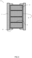
- a particular embodiment of the chemical combustion reactor (herein also referred to as reactor), wherein a flow path is provided in the longitudinal direction of the reactor is illustrated in Figure 1 .
- reactor a reactor
- the reactor may thus be alternatingly used as oxidizing and reducing reactor.
- the reactor comprises a reactor segment that comprises at least two porous active fixed beds (herein also referred to as simply the active beds) comprising a metal and/or an oxide thereof (herein also referred to as active material) placed in the flow path.
- the chemical combustion reactor and its constituents have a cylindrical shape.
- the shape of the active beds (4) may also be referred to as disk shaped (i.e. a flat circular shape).
- the beds are stacked in the longitudinal direction with a flat side of a first active bed to a flat side of a second active bed, wherein the flow path (2) is preferably provided perpendicular on the flat sides as also illustrated in Figure 1 .
- the flow path may be used for a gas stream provided through a gas inlet (12) and removed through a gas outlet (13) as depicted in Figure 1 .
- a spacing (17) is provided between the gas inlet and/or outlet and the active bed as illustrated in Figure 1 . This typically allows for an even distribution of the gas before entering the active beds.
- the gas-distributor typically actively distributes the gas in such a way that it will be evenly distributed before entering the active bed.
- the gas stream typically flows through the active beds and can thus come in contact with the active material, thereby generating a reaction front (i.e. the local site where the gas stream reacts with the metal and/or oxide thereof) that moves through the reactor along the longitudinal direction of the reactor.
- Flow parameters such as the pressure, temperature, concentration of the reducing and oxidizing agent and flow rate of the gas stream may i.a. be tuned to control the charging (reduction reaction) and discharging (oxidation reaction) of the system.
- it may be favorable to tune the flow parameters over the cycles as typically the active bed slightly changes in shape and/or composition after a cycle.
- the reaction front may move at an optimal rate to remain sharp, thin and locally well-defined such that it moves evenly through the reactor within an optimal range of reaction temperatures. Additionally, a more efficient use of the active material in the chemical combustion reactor is allowed.
- the reaction front moves through the chemical combustion reactor with a rate in the range of 0.05 to 0.5 mm/s, preferably about 0.2 mm/s.
- a chemical combustion reactor having a length of 2 meter (which would typically fit in a household environment), being discharged at a rate of 0.2 mm/s would last about 3 hours.
- active bed and "inactive insulating layer” (herein also referred to as inactive or insulating layer) relate to their respective reactivity and use when the system is operated.
- the active bed comprises a metal and/or an oxide thereof that can undergo a redox reaction to store or release heat. Because the active bed can undergo this redox reaction (typically with oxygen-containing or hydrogen-containing gas) at the condition applied during operation of the system, it is referred to as “active" bed.
- the inactive insulating layer if present, does essentially not undergo a redox reaction. It is essentially inert at these conditions.
- the difference in reactivity between the active bed and the inactive layer can for instance be achieved by basing the inactive layer on a material having a higher oxidation potential (i.e. more noble and thus less prone to oxidation) with respect to that of the active bed.
- a material having a higher oxidation potential i.e. more noble and thus less prone to oxidation
- the metal or the oxide thereof in the active bed can selectively be oxidized.
- the resulting oxidized product can then be selectively reduced over the inactive layer as well.
- the system further comprises one or more heaters (9) that are thermally connected to at least one active bed.
- the heaters are located in the reactor. This may be at the end of the gas inlet, where the heaters heat up the gas to the extent where enough energy can be provided to initiate the reaction.
- the heaters may be in contact with the active bed as illustrated in Figure 4 and Figure 5 .
- the heaters may for instance comprise heating elements that are fully or partially penetrating into the active bed. It is preferred to have the heaters in contact with the active bed, as the reactions typically require a high activation energy and thus high temperatures that may not be provided by a heated gas.
- the heaters may further be used to reinitiate a reaction after it ceases.
- Oxidation and reduction reactions can both either be exothermic or endothermic, depending on the nature of the reactants.
- the oxidation reaction and thus discharging of the reactor is exothermic.
- the released energy may be used as activation energy for subsequent oxidation reactions.
- a single initiation of an oxidation reaction may provide a chain of further oxidation reactions without requiring additional energy.
- a continuous energy supply such as placing the reactor in an oven, is typically needed for the metal oxide to be reduced in the reactor. Additionally, a continuous energy supply may be necessary for oxidation reactions that are insufficiently exothermic for a subsequent reaction to be initiated. If both the oxidation and reduction reactions are sufficiently exothermic, such energy supply will not be required.
- both reduction and oxidation reactions of the active material are exothermic. More preferably, it is preferred that they are sufficiently exothermic to provide the required activation energy for a subsequent reaction.
- the reaction can be self-sustainable. However, if too much heat would be transferred to the surroundings, the temperature of the chemical combustion reactor can drop below a critical minimal threshold (i.e. the minimum temperature at which the reaction is self-sustainable) and the discharging and/or charging may cease. However, if too little heat would be transferred, the temperature of the chemical combustion reactor can increase above a critical maximum threshold and the active material may sinter, melt, cluster or otherwise be damaged or displaced.
- the critical minimal threshold depends i.a. on the type of active material, the type of optional inactive material, the flow speed of reactive gases, and concentration of the reducing or oxidizing agent.
- the active bed comprises a metal and/or oxide thereof (depending on the charge status of the reactor).
- the metal may be a mixture of a plurality of metals such as separate metals, metal alloys, minerals, or combinations thereof.
- the metal is an active metal meaning that it is not inert but can be oxidized with oxygen.
- Suitable metals comprise one or more metal elements selected from the group consisting of Al, Ti, V, Cr, Mn, Fe, Co, Ni, Cu, Zn, Zr and Sn, preferably Cu, Fe, Ni, Co, or Mn, preferably Cu, Fe, Ni, Co, and/or Mn. More preferably, the metal comprises copper.
- the metal may be metallic metal, or may be part of a salt or mineral such as ilmenite.
- the active bed is porous to allow the reaction front to pass through the active bed.
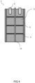
- the reactor segment comprises at least two active beds as depicted in Figures 1 and 2 . It is preferred that each bed has an individual porosity between 40-85%, preferably between 50-70%, more preferably between 50-60%, expressed as the percentage void of the total volume occupied by the active bed.
- the porosity typically provides good access of the gas to the active material, while maintaining optimal use of the space in the reactor to provide a high energy storage density.
- the porosity typically allows the gas to flow through the active bed even when the active material is expanded due to heating.
- each bed may have its individual porosity it is typically preferred when the reactor segment comprises multiple beds that the beds have similar porosities (e.g. between about +/- 10% variation from the porosity of the adjacent or other active beds in the segment or reactor).
- an evenly distributed reaction front may move continuously through the reactor. Generally, this ensures optimal efficiency.
- the active bed is typically built up from structures.
- the shape of the active bed may be tuned to provide optimal storage density and to provide a self-supporting structure (i.e. it should not compress without additional load present).
- These structures include, but are not limited to a single wire, multiple wires, wovens, non-wovens, particles, casted structures, mesh, grains, disks, rods, porous carriers such as zeolite having a metal and/or oxide thereof on its surface or in its volume, and combinations or stacks thereof.
- the structures may further be processed to reach the desired porosity e.g. by compression.
- the structures may for instance be shaped (e.g. woven) from a single or multiple wires.
- the diameter of the wires is typically tuned for an optimal balance between storage density and efficiency. Typically, the preferred wire diameter is between 0.05 and 0.3 mm. This dimension is particularly preferred for copper-comprising active beds.
- the single or multiple wires may comprise a single metal and/or oxide thereof, or it may have a core surrounded by a layer of the metal and/or oxide thereof.
- the layer may for example be sputtered or coated on the core.
- the core is typically an inert material, or at least does not participate significantly in the redox reactions under the given circumstances.
- Materials for such cores typically have a high oxidation resistance and high melting temperatures (e.g. above 1000°C). Such materials may include stainless steel, ceramics and/or alloys.
- the metal oxide is less physically stable than the metal. More metal may be oxidized (e.g. more than 50%) when using wires comprising a core as the core typically provides stability to minimize compromising the active bed.
- the catalyst may be a noble metal, preferably the catalyst and its respective oxide have a high melting temperature (e.g. above 1000 °C) and low volatility.
- a preferred catalyst may comprise platinum and/or palladium.
- the catalyst may be sputtered or coated on the active bed or on the structure before the active bed is formed. Alternatively or additionally, the catalyst may be provided as part of an alloy with the metal. Regardless of the application method, the catalyst and the metal and/or oxide thereof often form an alloy after one or more discharging/ charging cycles.
- the reactor segment further preferably comprises a porous inactive insulating layer (5) that separates the at least two active beds.
- the insulating layer typically tunes the heat conductivity of the reactor segment in the longitudinal direction of the reactor.
- the insulating layer may thus typically ensures a further control over the balance between the energy produced in the reaction front and the heat that is transferred in the longitudinal direction of the reactor. Accordingly, it preferably comprises a material with lower thermal conductivity than the active beds.
- Materials for the insulating layer typically have a high oxidation resistance and high melting temperatures (e.g. above 1000°C). These materials may for instance include ceramics, alloys, and/or stainless steel.
- the insulating layer is porous to allow the reaction front (i.a. the gas) to move through the insulating layer.
- the porous insulating layer has a porosity of up to 90%, preferably between 5-85%, more preferably between 20-70%, most preferably between 40-60%, expressed as the percentage void of the total volume occupied by the insulating layer.
- the porosity of the insulating layer is similar to the porosity of the active bed (e.g. between about +/- 10% variation from the porosity of the adjacent active bed). It may also be preferred that the reaction front is homogeneously redistributed in the direction perpendicular to the longitudinal direction of the reactor.
- the insulating layer typically prevents or at least limits sintering of the active material in those active beds that are separated by sandwiched insulating layer.
- the layer thus preferably has a higher melting temperature than the active material.
- the material of the insulating layer preferably inhibits sintering with the active material.
- the heat generation and heat transfer is well preserved, leading to more efficient use of the active material.
- maintenance of the reactor is facilitated if sintering of the active material over the entire length of the reactor is prevented.
- the active bed and/or insulating layer may comprise an anti-sintering material or catalytic material to lower the activation energy and required temperature.
- an anti-sintering material or catalytic material to lower the activation energy and required temperature.
- metals and/or metal oxides such as ZrO 2 , CaO, Mo and Ce may be sufficient.
- sintering may be limited by choosing a suitable metal and/or an oxide thereof.
- the insulating layer is as thin as possible in the longitudinal direction of the reactor.
- a thinner insulating layer typically enables a higher storage density in the reactor.
- the dimensions of the layer may be altered in accordance with the desired thermal conductivity relative to the active material.
- the ratio between the thickness of the active bed and the thickness of the layer is preferably at least 5:1, more preferably at least 50:1, most preferably at least 100:1.
- the reactor segment further comprises an insulating mantle (herein also simply referred to as mantle) that at least partially, preferably entirely, surrounds the active bed in the longitudinal direction of the reactor.
- the reactor segment further comprises the insulating layer, and accordingly the mantle at least partially, preferably entirely, surrounds the active bed and the insulating layer in the longitudinal direction of the reactor.
- the mantle is insulating to advantageously enable the reaction front to continuously flow through the reactor, without excess heat transfer to the adjacent layer e.g. the reactor wall (14) as illustrated in Figure 1 , or the surroundings.
- the insulating mantle is preferably not too little insulating such that too much heat is transferred to the surroundings such that the reactions would cease due to limited heating of the active material to a temperature higher than the critical minimal temperature required to initiate the reaction.
- the reactor may, however, also be used as heat supply when submerged in a tank (16) as illustrated in Figure 1 e.g. an HTF tank as disclosed in WO 2019/050398 , wherein the insulating mantle transfers heat to the HTF via the adjacent layer (e.g. the reactor wall (14)).
- the HTF may circulate around the reactor wall (14) due to convection.
- the tank may also comprise a means to actively circulate the HTF fluid around the reactor wall such as a pump, this is in the art also known as a cooling jacket.
- the heated active bed may expand in the direction perpendicular to the flow path.
- the expansion is approximately 2.5% of the diameter of the active bed.
- the active bed may be permanently deformed or the active bed may compress and/or deform the adjacent material.
- the active bed may contract again to dimensions similar to its initial state after the reaction front has passed due to a decreased temperature. This can leave a gap between the adjacent layer and the active bed, if no suitable counter-measures would be taken. A subsequent gas stream may therefore partially pass through the gap instead of through the active material, reducing efficiency.
- the mantle comprises a compressible material that after compression at least partially decompresses to its initial shape.
- Compressible may also be interpreted as flexible, malleable, ductile, elastic, formable and the like which all herein at least mean that the mantle material is preferably capable of at least partially reforming back to its initial shape after deformation. More preferably the material reforms completely back to its initial shape.
- the mantle directly (partially or entirely) surrounds the active bed and optional insulating layer. Directly surrounding herein means that no other layer or structure is placed in between the insulating mantle and the active bed and optional insulating layer assembly. If the active bed does not suffer from expansion and contraction in such an extent that a compressible material is present in the mantle, an additional structure (e.g. an intermediate, rigid wall) may be placed in between the insulating mantle and the active bed and optional insulating layer assembly.
- an additional structure e.g. an intermediate, rigid wall
- the mantle material preferably has a higher gas flow resistance than the active bed and the optional insulating layer.
- the higher resistance typically allows for the gas stream to flow through the active material and optional insulating layer instead of leaking to the mantle.
- the mantle material may therefore comprise ceramics such as ceramic fibers, ceramic fabrics, open- and/or closed-cell ceramic structures, or inert metal meshes, open- and/or closed-cell foams or combinations thereof.
- the thickness of the insulating mantle typically depends on the desired balance between insulation and heat transfer. Typically, the thickness of the mantle exceeds the maximum expansion of the active bed. The thickness is preferably 1 to 15% of the easy direction of the active bed perpendicular to the longitudinal direction of the reactor. More preferably the thickness is from 2 to 10%, most preferably from 2 to 6%. Easy direction herein relates to the length of the active bed in the direction that expands the furthest when the active bed is heated. For instance, in a cylindrically shaped reactor the easy direction is the diameter of the active bed.
- the reactor segment further preferably comprises a support structure (7) comprising a fixation element (8) as illustrated in Figure 3 .
- the support structure supports or carries the active bed, optionally the insulating layer and preferably the insulating mantle as well.
- the support structure can limit the forces that of the active beds exert on one another and on the optional insulating layer (i.e . the pressure of the load of the higher-placed active bed onto the lower-placed active bed and optional insulating layer). Additional forces may be exerted on the active beds due to a pressure drop over the complete reactor during operation. Limiting the forces can also be achieved by placing the reactor non-vertically, e.g.
- the assembly as illustrated in Figure 3 may be stackable in and removable from the reactor as described herein below, and can accordingly be considered a cartridge (11).
- the fixation element may be removably fixated to the support structure to simplify placing the constituents (i.a. active beds and optional insulating layer) in the support structure.
- the fixation element may for example be in the form of a retaining ring for a cylindrical shaped reactor segment. Usually a fixation element is placed on top of the placed constituents and a fixation element is placed below (in the longitudinal direction of the reactor). It may be preferred to secure one or more of the fixation elements to increase the stability.
- An additional aspect of the present invention is directed to the cartridge (11) comprising a reactor segment and a support structure.
- An example of such cartridge is illustrated in Figures 3 and 6 .
- the cartridge is preferably adapted to be removable from and stackable within the reactor.
- Figure 6 illustrates the stackable nature of the cartridges within the reactor.
- Cartridges allow this replacement in an easy fashion to restore functionality of the reactor. Additionally, it typically allows for full replacement of the content of the reactor in an simple manner.
- a gap filled with a linking structure can be created when stacking two or more reaction segments comprising a support structure or when stacking two or more cartridges.
- This linking structure may advantageously be placed to enable a gapless continuation of the reaction front from one reaction segment to a second reaction segment.
- the linking structure may comprise an additional active bed, or at least it may comprise the same active material. Additionally or alternatively, it may comprise an insulating material (e.g. similar to the material used for the insulating layer). The chosen material may for instance be dependent on the dimensions of the gap.
- the system preferably comprises a temperature sensor (10), as illustrated in Figures 4 and 5 , that is preferably located in the chemical combustion reactor such that it can measure a representative temperature of at least one active bed.
- the sensor is typically used as an indication of the movement of the reaction front.
- the sensor may comprise a thermocouple with one or more measurement points. Additionally or alternatively, it may comprise temperature fiber optic sensors such as fiber Bragg grating sensors, for example glass fibers.
- these fibers have a small diameter that may minimize the influence on the performance of the reactor. Furthermore, the glass typically does not interfere significantly with the heat transfer.
- the temperature sensor may further also be used as a support structure.
- the temperature sensor usually measures a representative temperature of at least one active bed.
- the representative temperature may depend on the shape of the active bed. For a cylindrical active bed, the representative temperature is typically in the center of the active bed.
- the temperature within the reactor may be dependent on the active material used as the temperature typically rises up to the melting temperature of the active material. For instance, when using copper and/or copper oxide the temperature may rise up to 1000°C. Therefore, the temperature sensor should withstand such temperatures and should be capable of measuring these. Moreover, it is typically required that all constituents within the system are able to withstand the obtained temperatures.
- the system may comprise multiple chemical combustion reactors as described herein. Typically, energy for a couple hours is provided from one reactor. A plurality of reactors may thus be used as energy supply for short periods e.g. for households when the renewable energy source is low. In embodiments with the plurality of the chemical combustion reactors, it is preferred that each reactor can be operated (i.e. charged and discharged) independently. This provides additional flexibility to the system and enables for instance simultaneous charging and discharging of the system and energy conversion, which may be desirable during a change of circumstances, such as going from an energy excess to shortage or vice versa.
- Charging of the chemical combustion reactor can be carried out by providing a reducing gas stream, preferably a reducing gas stream comprising methane or hydrogen, and leading the reducing gas stream into the reactor and allowing the reducing gas stream to react with a metal oxide in the reactor to reduce the metal oxide.
- the system further comprises a reducing gas supply system.
- a reducing gas hydrogen is used. This gas advantageously typically only produces water upon charging of the reactor.
- the system further comprises a condenser to liquefy the water.
- Discharging of the chemical combustion reactor can be carried out by providing an oxidizing gas stream, preferably an oxidizing gas stream comprising oxygen, and leading the oxidizing gas stream into the reactor and allowing the oxidizing gas stream to react with the metal to oxidize the metal.
- the system further comprises an oxidizing gas supply system.
- a single inlet and a single gas outlet for the chemical combustion reactor is preferred, as this improves the reliability and decreases the chance of system failures.
- the inlet and outlet of the reactor can be used as such for both the reduction and the oxidation gas streams, such that the reactor is discharged and charged with gas streams flowing in the same direction.
- the direction in which the reactor is charged may also be reverse of the direction in which the reactor is discharged.
- the inlet and outlet may thus switch their function: the inlet becomes the outlet and vice versa.
- a particular method for storing energy in a system in accordance with the present invention comprises providing a reducing gas stream, preferably a reducing gas stream comprising hydrogen gas, and leading said reducing gas stream into the chemical combustion reactor and allowing the reducing gas stream to react with a metal oxide in the chemical combustion reactor to reduce the metal.
- a particular method for discharging energy from a system in accordance with the present invention comprises providing an oxidizing gas stream, preferably an oxidizing gas stream comprising oxygen gas, and leading said oxidizing gas stream into the reactor and allowing the oxidizing gas stream to react with a metal in the reactor to oxidize the metal.
- the present invention can be illustrated by the following nonlimiting examples.
- Example 1 Reactor segment comprising copper active beds
- a tube shaped reactor segment was made in a stainless steel tube containing 17 active beds separated by inactive insulating layers and surrounded by an insulating mantle.
- the active beds were stacks of copper meshes and had a diameter of 77.5 mm.
- the copper mesh structure was prepared from wires with about 0.1 mm diameter.
- the porosity of the active beds was 76%.
- the copper mass was 2185.8 g.
- the insulating mantle had a thickness of 1mm.
- the inactive insulating layers were stainless steel (SS) meshes, with a 77.5 mm diameter and a wire diameter of about 0.2 mm.
- a stainless steel tube with a length of 200 mm and retaining rings were used to assemble the reactor segment.
- the reactor segment was assembled using multipoint thermocouples. A stainless steel tube with 200mm length was used. The six heaters were set in the upper part with a depth of approximately 35mm.
- the stainless steel meshes were inserted in between of the copper active beds every 1.5 cm to match the spacing of the thermocouples.
- the head of a thermocouple with 6 sensors was placed 5 mm in the active bed.
- a 80 mm diameter circular filter of stainless steel mesh was place on the bottom to prevent small particle pollution and a retaining ring was used to hold it.
- the heaters were inserted in the stacks of active beds as illustrated in Figure 4 and the active beds were stacked and kept in place via compression on the top and bottom before the insulation mantle was placed around it.
- the stack including insulating mantle was carefully inserted in the stainless steel tube.
- the total mass of the cartridge was 3355.1 g.
- Example 2 Reactor segment comprising copper active beds
- a tube shaped reactor segment was made of a stainless steel tube containing 6 active beds separated by inactive insulating layers and surrounded by an insulating mantle.
- the active beds were stacks of copper meshes and had a diameter of 77.5 mm.
- the copper mesh structure was prepared from wires with about 0.1 mm diameter.
- the porosity of the active beds was 76%.
- the copper mass was 1022.23 g.
- the insulating mantle had a thickness of 1mm.
- the inactive insulating layers were stainless steel (SS) meshes, with a 77.5 mm diameter and a wire diameter of about 0.2 mm.
- a stainless steel tube of 100 mm length and retaining rings were used to assemble the cartridge.
- the reactor segment was assembled using a multipoint thermocouple.
- the stainless steel meshes were inserted in the middle of the copper active beds every 1.5 cm to match the spacing of the thermocouple.
- the active beds were separated by the inactive stainless steel meshes were stacked and kept in place via compression on the top and bottom before insulation mantle was placed around. The stack was carefully inserted in the stainless steel tube such that the insulation mantle kept in place. The total mass of the cartridge was 1382.2 g. At the bottom a filter element was inserted between the last active bed and a retaining ring.
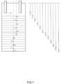
- the internal layout of the reactor segment is schematically illustrated in Figure 8 , where the dotted line indicates the thermocouple with the black dots as temperature sensors.
- the linking structure is positioned at the top of this bottom segment.
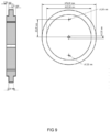
- a stack of copper meshes with a total mass of 99.93 g was used. Small holes were drilled in the linking structure to bind the copper meshes together using copper wire. A single plie layer of insulating material was applied to the outer perimeter of the linking structure, which was held in place by copper wire before the mass was weighted. A schematic illustration and top view hereof is illustrated in Figure 9 .
- Example 1 and Example 2 are stacked and connected by a linking structure according to Example 3.
- the total length was 300mm with a copper mass of 3307.7 g.
- a schematic overview of stacking is illustrated in Figure 6 .
Landscapes
- Chemical & Material Sciences (AREA)
- Chemical Kinetics & Catalysis (AREA)
- Organic Chemistry (AREA)
- Engineering & Computer Science (AREA)
- General Chemical & Material Sciences (AREA)
- Physics & Mathematics (AREA)
- Thermal Sciences (AREA)
- Mechanical Engineering (AREA)
- General Engineering & Computer Science (AREA)
- Physical Or Chemical Processes And Apparatus (AREA)
Claims (13)
- System zur Energiespeicherung, umfassend einen chemischen Verbrennungsreaktor (1), wobei ein Strömungsweg (2) in einer Längsrichtung des Reaktors vorgesehen ist, wobei der Reaktor ein Reaktorsegment (3) umfasst, das zumindest zwei poröse aktive Festbetten (4) umfasst, angeordnet in dem Strömungsweg, wobei die aktiven Betten ein Metall und/oder ein Oxid davon umfassen,dadurch gekennzeichnet, dass die aktiven Betten durch eine poröse, inaktive Isolierschicht (5) getrennt sind, unddass die aktiven Betten und die Isolierschicht zumindest teilweise direkt von einem isolierenden Mantel (6) in Längsrichtung des Reaktors umgeben sind.
- System nach dem vorhergehenden Anspruch, wobei das Reaktorsegment (3) eine Trägerstruktur (7) umfasst, wobei die Trägerstruktur ein Befestigungselement (8) umfasst, das zum Tragen zumindest der aktiven Betten (4) und optional der Isolierschicht (5) in dem chemischen Verbrennungsreaktor (1) angepasst ist.
- System nach einem der vorhergehenden Ansprüche, ferner umfassend ein oder mehrere Heizgeräte (9), vorzugsweise so angeordnet in dem chemischen Verbrennungsreaktor (1), dass sie mit zumindest einem aktiven Bett (4) thermisch verbunden sind, wobei das eine oder die mehreren Heizgeräte vorzugsweise ein Heizelement umfassen, das das aktive Bett durchdringt, mit dem es thermisch verbunden ist.
- System nach einem der vorhergehenden Ansprüche, ferner umfassend einen Temperatursensor (10), vorzugsweise in dem chemischen Verbrennungsreaktor (1) angeordnet und angepasst um eine repräsentative Temperatur zumindest eines aktiven Bettes (4) zu messen, wobei der Temperatursensor vorzugsweise ein Sensorelement umfasst, das das aktive Bett, typischerweise die Mitte des aktiven Bettes, durchdringt, an das es angepasst ist, um dessen Temperatur zu messen.
- System nach einem der vorhergehenden Ansprüche, wobei das Metall und/oder ein Oxid davon ein Metallelement umfasst, ausgewählt aus der Gruppe bestehend aus Al, Ti, V, Cr, Mn, Fe, Co, Ni, Cu, Zn, Zr, Sn und Kombinationen davon, vorzugsweise Cu, Fe, Ni, Co und Mn, besonders bevorzugt Kupfer.
- System nach einem der vorhergehenden Ansprüche, wobei die aktiven Betten (4) ferner einen Katalysator, vorzugsweise Platin und/oder Palladium, umfassen.
- System nach einem der vorhergehenden Ansprüche, wobei die aktiven Betten (4) individuell eine Porosität zwischen 40-85%, vorzugsweise zwischen 50-70%, besonders bevorzugt zwischen 50-60% haben, ausgedrückt als prozentualer Leerraum, bezogen auf das vom Aktivbett eingenommene Gesamtvolumen.
- System nach einem der vorhergehenden Ansprüche, wobei die poröse Isolierschicht (5) ein inaktives Material mit geringerer Wärmeleitfähigkeit als das Metall und/oder Oxid davon umfasst, wobei das inaktive Material vorzugsweise rostfreien Stahl umfasst.
- System nach einem der vorhergehenden Ansprüche, wobei die poröse Isolierschicht (5) eine Porosität von bis zu 90 %, vorzugsweise zwischen 5-85 %, stärker bevorzugt zwischen 20-70 %, am meisten bevorzugt zwischen 40-60 % hat, ausgedrückt als prozentualer Leerraum des von der Isolierschicht eingenommenen Gesamtvolumens,.
- System nach einem der vorhergehenden Ansprüche, wobei der isolierende Mantel (6) ein komprimierbares Material umfasst, das sich nach der Kompression zumindest teilweise in seine ursprüngliche Form dekomprimiert, vorzugsweise vollständig in seine ursprüngliche Form dekomprimiert, und wobei der isolierende Mantel einen höheren Gasströmungswiderstand hat als jedes der aktiven Betten.
- Kartusche (11) zur Verwendung in einem System nach einem der vorhergehenden Ansprüche, umfassend ein Reaktorsegment (3), wie in einem der vorhergehenden Ansprüche definiert, und eine Trägerstruktur zum Tragen des Reaktorsegments, wobei die Kartusche angepasst ist, um entfernbar aus und stapelbar innerhalb des chemischen Verbrennungsreaktors (1) nach einem der vorhergehenden Ansprüche zu sein.
- Verfahren zur Energiespeicherung in einem System nach einem der Ansprüche 1 bis 10, wobei das Verfahren Bereitstellen eines reduzierenden Gasstroms umfasst, vorzugsweise eines reduzierenden Gasstroms umfassend Wasserstoffgas, und Leiten des reduzierenden Gasstroms in den chemischen Verbrennungsreaktor (1) und Ermöglichen des Reagierens des reduzierenden Gasstroms mit einem Metall in dem chemischen Verbrennungsreaktor, um das Metall zu reduzieren.
- Verfahren zum Abführen von Energie aus einem System nach einem der Ansprüche 1 bis 10, wobei das Verfahren Bereitstellen eines oxidierenden Gasstroms umfasst, vorzugsweise eines oxidierenden Gasstroms umfassend Sauerstoffgas, und Leiten des oxidierenden Gasstroms in den chemischen Verbrennungsreaktor (1) und Ermöglichen des Reagierens des oxidierenden Gasstroms mit einem Metall in dem chemischen Verbrennungsreaktor, um das Metall zu oxidieren.
Applications Claiming Priority (2)
| Application Number | Priority Date | Filing Date | Title |
|---|---|---|---|
| EP20164249.3A EP3882554A1 (de) | 2020-03-19 | 2020-03-19 | Interne konfiguration für redox-basierte wärmespeichersysteme |
| PCT/NL2021/050188 WO2021187987A1 (en) | 2020-03-19 | 2021-03-19 | Internal configuration for redox-based heat storage systems |
Publications (2)
| Publication Number | Publication Date |
|---|---|
| EP4121709A1 EP4121709A1 (de) | 2023-01-25 |
| EP4121709B1 true EP4121709B1 (de) | 2025-05-07 |
Family
ID=69846351
Family Applications (2)
| Application Number | Title | Priority Date | Filing Date |
|---|---|---|---|
| EP20164249.3A Withdrawn EP3882554A1 (de) | 2020-03-19 | 2020-03-19 | Interne konfiguration für redox-basierte wärmespeichersysteme |
| EP21714276.9A Active EP4121709B1 (de) | 2020-03-19 | 2021-03-19 | Interne konfiguration für redox-basierte wärmespeichersysteme |
Family Applications Before (1)
| Application Number | Title | Priority Date | Filing Date |
|---|---|---|---|
| EP20164249.3A Withdrawn EP3882554A1 (de) | 2020-03-19 | 2020-03-19 | Interne konfiguration für redox-basierte wärmespeichersysteme |
Country Status (3)
| Country | Link |
|---|---|
| US (1) | US12298084B2 (de) |
| EP (2) | EP3882554A1 (de) |
| WO (1) | WO2021187987A1 (de) |
Families Citing this family (1)
| Publication number | Priority date | Publication date | Assignee | Title |
|---|---|---|---|---|
| CN118463687B (zh) * | 2024-06-04 | 2024-11-12 | 江苏瑞鼎环境工程有限公司 | 一种焚烧炉低温段烟气余热的储冷系统及其工艺 |
Family Cites Families (36)
| Publication number | Priority date | Publication date | Assignee | Title |
|---|---|---|---|---|
| US4034569A (en) * | 1974-11-04 | 1977-07-12 | Tchernev Dimiter I | Sorption system for low-grade (solar) heat utilization |
| US4161211A (en) * | 1975-06-30 | 1979-07-17 | International Harvester Company | Methods of and apparatus for energy storage and utilization |
| DE2717101C2 (de) * | 1977-04-18 | 1986-04-03 | Didier Engineering Gmbh, 4300 Essen | Verfahren zur katalytischen Umsetzung eines reduzierenden Gases |
| US4470931A (en) * | 1978-10-24 | 1984-09-11 | The Standard Oil Company | Combination fixed-fluid bed reactor |
| US4341262A (en) * | 1980-05-05 | 1982-07-27 | Alspaugh Thomas R | Energy storage system and method |
| US4424397A (en) * | 1982-09-27 | 1984-01-03 | E. I. Du Pont De Nemours And Company | Formaldehyde process |
| JPS6152550A (ja) * | 1984-08-21 | 1986-03-15 | Hitachi Chem Co Ltd | 化学蓄熱給湯システム |
| JPS62288495A (ja) * | 1986-06-03 | 1987-12-15 | Sumitomo Metal Ind Ltd | 熱交換器 |
| US4928496A (en) * | 1989-04-14 | 1990-05-29 | Advanced Materials Corporation | Hydrogen heat pump |
| CA2171279C (fr) * | 1996-03-07 | 2007-09-18 | Richard Auger | Reacteur pour le traitement d'un liquide |
| US6117812A (en) * | 1998-10-06 | 2000-09-12 | China Petro-Chemical Corporation | Dual functional catalyst of packing type and the catalytic distillation equipment |
| US6478077B1 (en) * | 2001-05-15 | 2002-11-12 | Sandia National Laboratories | Self supporting heat transfer element |
| US7393510B2 (en) * | 2003-03-25 | 2008-07-01 | Crystaphase International, Inc. | Decontamination of process streams |
| JP4167607B2 (ja) * | 2004-02-27 | 2008-10-15 | 株式会社豊田自動織機 | 水素貯蔵タンク |
| EP1723844A1 (de) | 2005-05-18 | 2006-11-22 | Nederlandse Organisatie voor toegepast-natuurwetenschappelijk Onderzoek TNO | Verfahren für die Regulierung von Wärme und CO2 Inhalt in der Luft eines geschlossenen Raumes |
| DE102006010636A1 (de) * | 2005-12-19 | 2007-06-21 | BLüCHER GMBH | Sorptionsspeichereinheit für Gase |
| DE102007026712A1 (de) * | 2007-06-06 | 2008-12-11 | Uhde Gmbh | Vorrichtung und Verfahren für katalytische Gasphasenreaktionen sowie deren Verwendung |
| WO2010091171A1 (en) * | 2009-02-04 | 2010-08-12 | Purdue Research Foundation | Finned heat exchangers for metal hydride storage systems |
| US8778063B2 (en) * | 2009-02-04 | 2014-07-15 | Purdue Research Foundation | Coiled and microchannel heat exchangers for metal hydride storage systems |
| GB0918246D0 (en) * | 2009-10-19 | 2009-12-02 | Davy Process Techn Ltd | Apparatus |
| WO2012005277A1 (ja) * | 2010-07-06 | 2012-01-12 | 株式会社ルネッサンス・エナジー・リサーチ | 一酸化炭素変成装置及び方法並びに水素製造装置 |
| JP5698056B2 (ja) * | 2011-03-31 | 2015-04-08 | 株式会社豊田中央研究所 | 化学蓄熱装置 |
| EP2515037A1 (de) | 2011-04-21 | 2012-10-24 | Nederlandse Organisatie voor toegepast -natuurwetenschappelijk onderzoek TNO | Chemische Schlaufenverbrennung mit festem Bett |
| JP6056691B2 (ja) * | 2013-07-12 | 2017-01-11 | アイシン精機株式会社 | 化学蓄熱装置 |
| WO2016210433A1 (en) * | 2015-06-26 | 2016-12-29 | The Regents Of The University Of California | High temperature synthesis for power production and storage |
| JP6493338B2 (ja) * | 2015-12-24 | 2019-04-03 | 株式会社豊田自動織機 | 化学蓄熱装置 |
| US10054140B2 (en) * | 2016-02-12 | 2018-08-21 | Crystaphase Products, Inc. | Use of treating elements to facilitate flow in vessels |
| JP6868393B2 (ja) * | 2016-12-28 | 2021-05-12 | 日本ペイントホールディングス株式会社 | 蓄放熱装置 |
| US10329225B2 (en) * | 2017-01-20 | 2019-06-25 | Saudi Arabian Oil Company | Dual catalyst processes and systems for propylene production |
| EP3382314A1 (de) * | 2017-03-30 | 2018-10-03 | Nederlandse Organisatie voor toegepast- natuurwetenschappelijk onderzoek TNO | Verbesserte tcm-herstellung und verwendung |
| EP3453998A1 (de) | 2017-09-06 | 2019-03-13 | Nederlandse Organisatie voor toegepast- natuurwetenschappelijk onderzoek TNO | System zur energiespeicherung mit wärmetauschern |
| EP3453997A1 (de) * | 2017-09-06 | 2019-03-13 | Nederlandse Organisatie voor toegepast- natuurwetenschappelijk onderzoek TNO | System zur energiespeicherung mit einem wärmetransferfluidtank |
| AU2018386998B2 (en) * | 2017-12-21 | 2023-03-30 | Casale Sa | Multi-bed catalytic converter |
| KR102142355B1 (ko) * | 2018-11-23 | 2020-08-07 | 한국화학연구원 | 촉매 비활성화 방지를 위한 다층의 촉매층 배열을 갖는 cdr 반응기 |
| WO2020146361A1 (en) * | 2019-01-07 | 2020-07-16 | Board Of Trustees Of Michigan State University | System and operation for thermochemical renewable energy storage |
| US20230266074A1 (en) * | 2022-02-20 | 2023-08-24 | Molecule Works Inc. | Device for mass and/or heat transfer and process for capturing a molecule in a process fluid using the device |
-
2020
- 2020-03-19 EP EP20164249.3A patent/EP3882554A1/de not_active Withdrawn
-
2021
- 2021-03-19 US US17/906,306 patent/US12298084B2/en active Active
- 2021-03-19 EP EP21714276.9A patent/EP4121709B1/de active Active
- 2021-03-19 WO PCT/NL2021/050188 patent/WO2021187987A1/en not_active Ceased
Also Published As
| Publication number | Publication date |
|---|---|
| EP3882554A1 (de) | 2021-09-22 |
| US12298084B2 (en) | 2025-05-13 |
| WO2021187987A1 (en) | 2021-09-23 |
| EP4121709A1 (de) | 2023-01-25 |
| US20230139510A1 (en) | 2023-05-04 |
Similar Documents
| Publication | Publication Date | Title |
|---|---|---|
| EP1636132B1 (de) | Methode zur herstellung von elektrizität mittels temperaturwechselreformierung und festoxid-brennstoffzelle | |
| US5366819A (en) | Thermally integrated reformer for solid oxide fuel cells | |
| US6641795B2 (en) | Reformer and method for operation thereof | |
| US20150129805A1 (en) | Method for producing co and/or h2 in an alternating operation between two operating modes | |
| EP0925107B1 (de) | Shift converter | |
| JP2011020118A (ja) | 温度制御付きのマイクロチャンネル反応器 | |
| EP2336083A1 (de) | Gasgenerator und Verfahren zur Umwandlung eines Brennstoffs in ein sauerstoffarmen Gases und/oder wasserstoffangereicherten Gases | |
| McCrary et al. | An experimental study of the CO2 CH4 reforming-methanation cycle as a mechanism for converting and transporting solar energy | |
| EP1519784A2 (de) | Dampfreformierung von katalysatorstrukturen | |
| US20200173734A1 (en) | System for energy storage including a heat transfer fluid tank | |
| Agrafiotis et al. | Cobalt oxide-based structured thermochemical reactors/heat exchangers for solar thermal energy storage in Concentrated Solar Power plants | |
| EP4121709B1 (de) | Interne konfiguration für redox-basierte wärmespeichersysteme | |
| Delsman et al. | Comparison between conventional fixed-bed and microreactor technology for a portable hydrogen production case | |
| WO2019050397A1 (en) | ENERGY STORAGE SYSTEM COMPRISING HEAT EXCHANGERS | |
| EP1953858B1 (de) | Brennstoffzelle | |
| KR100719484B1 (ko) | 금속모노리스 촉매를 이용한 컴팩트형 수증기개질구조촉매 및 이를 이용한 수소의 제조방법 | |
| WO2014042800A1 (en) | Catalytic plate reactors | |
| EP3121547A1 (de) | System und verfahren zur speicherung und abgabe von wärme | |
| CN100540459C (zh) | 使用变温重整和固态氧化物燃料电池发电的方法 | |
| Agrafiotis et al. | Hybrid sensible/thermochemical storage of solar energy in cascades of redox-oxide-pair-based porous ceramics | |
| JP2008239390A (ja) | 改質反応装置、燃料電池発電装置および水素製造装置 | |
| EP2006945A1 (de) | Verfahren zum Starten einer Brennstoffzellenanordnung | |
| KR100905422B1 (ko) | 연료개질기 및 그 제조방법 | |
| US11325090B1 (en) | Catalytic solar reactor | |
| EA043688B1 (ru) | Производство водорода из аммиака |
Legal Events
| Date | Code | Title | Description |
|---|---|---|---|
| STAA | Information on the status of an ep patent application or granted ep patent |
Free format text: STATUS: UNKNOWN |
|
| STAA | Information on the status of an ep patent application or granted ep patent |
Free format text: STATUS: THE INTERNATIONAL PUBLICATION HAS BEEN MADE |
|
| PUAI | Public reference made under article 153(3) epc to a published international application that has entered the european phase |
Free format text: ORIGINAL CODE: 0009012 |
|
| STAA | Information on the status of an ep patent application or granted ep patent |
Free format text: STATUS: REQUEST FOR EXAMINATION WAS MADE |
|
| 17P | Request for examination filed |
Effective date: 20221010 |
|
| AK | Designated contracting states |
Kind code of ref document: A1 Designated state(s): AL AT BE BG CH CY CZ DE DK EE ES FI FR GB GR HR HU IE IS IT LI LT LU LV MC MK MT NL NO PL PT RO RS SE SI SK SM TR |
|
| DAV | Request for validation of the european patent (deleted) | ||
| DAX | Request for extension of the european patent (deleted) | ||
| P01 | Opt-out of the competence of the unified patent court (upc) registered |
Effective date: 20230522 |
|
| GRAP | Despatch of communication of intention to grant a patent |
Free format text: ORIGINAL CODE: EPIDOSNIGR1 |
|
| STAA | Information on the status of an ep patent application or granted ep patent |
Free format text: STATUS: GRANT OF PATENT IS INTENDED |
|
| RIC1 | Information provided on ipc code assigned before grant |
Ipc: B01J 8/04 20060101ALI20240404BHEP Ipc: B01J 8/00 20060101ALI20240404BHEP Ipc: F28D 20/00 20060101AFI20240404BHEP |
|
| INTG | Intention to grant announced |
Effective date: 20240426 |
|
| GRAJ | Information related to disapproval of communication of intention to grant by the applicant or resumption of examination proceedings by the epo deleted |
Free format text: ORIGINAL CODE: EPIDOSDIGR1 |
|
| STAA | Information on the status of an ep patent application or granted ep patent |
Free format text: STATUS: REQUEST FOR EXAMINATION WAS MADE |
|
| INTC | Intention to grant announced (deleted) | ||
| GRAP | Despatch of communication of intention to grant a patent |
Free format text: ORIGINAL CODE: EPIDOSNIGR1 |
|
| STAA | Information on the status of an ep patent application or granted ep patent |
Free format text: STATUS: GRANT OF PATENT IS INTENDED |
|
| INTG | Intention to grant announced |
Effective date: 20241017 |
|
| GRAS | Grant fee paid |
Free format text: ORIGINAL CODE: EPIDOSNIGR3 |
|
| GRAA | (expected) grant |
Free format text: ORIGINAL CODE: 0009210 |
|
| STAA | Information on the status of an ep patent application or granted ep patent |
Free format text: STATUS: THE PATENT HAS BEEN GRANTED |
|
| AK | Designated contracting states |
Kind code of ref document: B1 Designated state(s): AL AT BE BG CH CY CZ DE DK EE ES FI FR GB GR HR HU IE IS IT LI LT LU LV MC MK MT NL NO PL PT RO RS SE SI SK SM TR |
|
| REG | Reference to a national code |
Ref country code: GB Ref legal event code: FG4D |
|
| REG | Reference to a national code |
Ref country code: CH Ref legal event code: EP |
|
| REG | Reference to a national code |
Ref country code: DE Ref legal event code: R096 Ref document number: 602021030404 Country of ref document: DE |
|
| REG | Reference to a national code |
Ref country code: IE Ref legal event code: FG4D |
|
| REG | Reference to a national code |
Ref country code: NL Ref legal event code: FP |
|
| PG25 | Lapsed in a contracting state [announced via postgrant information from national office to epo] |
Ref country code: PT Free format text: LAPSE BECAUSE OF FAILURE TO SUBMIT A TRANSLATION OF THE DESCRIPTION OR TO PAY THE FEE WITHIN THE PRESCRIBED TIME-LIMIT Effective date: 20250908 Ref country code: ES Free format text: LAPSE BECAUSE OF FAILURE TO SUBMIT A TRANSLATION OF THE DESCRIPTION OR TO PAY THE FEE WITHIN THE PRESCRIBED TIME-LIMIT Effective date: 20250507 Ref country code: FI Free format text: LAPSE BECAUSE OF FAILURE TO SUBMIT A TRANSLATION OF THE DESCRIPTION OR TO PAY THE FEE WITHIN THE PRESCRIBED TIME-LIMIT Effective date: 20250507 |
|
| REG | Reference to a national code |
Ref country code: LT Ref legal event code: MG9D |
|
| PG25 | Lapsed in a contracting state [announced via postgrant information from national office to epo] |
Ref country code: NO Free format text: LAPSE BECAUSE OF FAILURE TO SUBMIT A TRANSLATION OF THE DESCRIPTION OR TO PAY THE FEE WITHIN THE PRESCRIBED TIME-LIMIT Effective date: 20250807 Ref country code: GR Free format text: LAPSE BECAUSE OF FAILURE TO SUBMIT A TRANSLATION OF THE DESCRIPTION OR TO PAY THE FEE WITHIN THE PRESCRIBED TIME-LIMIT Effective date: 20250808 |
|
| PG25 | Lapsed in a contracting state [announced via postgrant information from national office to epo] |
Ref country code: PL Free format text: LAPSE BECAUSE OF FAILURE TO SUBMIT A TRANSLATION OF THE DESCRIPTION OR TO PAY THE FEE WITHIN THE PRESCRIBED TIME-LIMIT Effective date: 20250507 |
|
| REG | Reference to a national code |
Ref country code: AT Ref legal event code: MK05 Ref document number: 1792874 Country of ref document: AT Kind code of ref document: T Effective date: 20250507 |
|
| PG25 | Lapsed in a contracting state [announced via postgrant information from national office to epo] |
Ref country code: BG Free format text: LAPSE BECAUSE OF FAILURE TO SUBMIT A TRANSLATION OF THE DESCRIPTION OR TO PAY THE FEE WITHIN THE PRESCRIBED TIME-LIMIT Effective date: 20250507 |
|
| PG25 | Lapsed in a contracting state [announced via postgrant information from national office to epo] |
Ref country code: HR Free format text: LAPSE BECAUSE OF FAILURE TO SUBMIT A TRANSLATION OF THE DESCRIPTION OR TO PAY THE FEE WITHIN THE PRESCRIBED TIME-LIMIT Effective date: 20250507 |
|
| PG25 | Lapsed in a contracting state [announced via postgrant information from national office to epo] |
Ref country code: AT Free format text: LAPSE BECAUSE OF FAILURE TO SUBMIT A TRANSLATION OF THE DESCRIPTION OR TO PAY THE FEE WITHIN THE PRESCRIBED TIME-LIMIT Effective date: 20250507 |
|
| PG25 | Lapsed in a contracting state [announced via postgrant information from national office to epo] |
Ref country code: RS Free format text: LAPSE BECAUSE OF FAILURE TO SUBMIT A TRANSLATION OF THE DESCRIPTION OR TO PAY THE FEE WITHIN THE PRESCRIBED TIME-LIMIT Effective date: 20250807 |
|
| PG25 | Lapsed in a contracting state [announced via postgrant information from national office to epo] |
Ref country code: IS Free format text: LAPSE BECAUSE OF FAILURE TO SUBMIT A TRANSLATION OF THE DESCRIPTION OR TO PAY THE FEE WITHIN THE PRESCRIBED TIME-LIMIT Effective date: 20250907 |
|
| PG25 | Lapsed in a contracting state [announced via postgrant information from national office to epo] |
Ref country code: LV Free format text: LAPSE BECAUSE OF FAILURE TO SUBMIT A TRANSLATION OF THE DESCRIPTION OR TO PAY THE FEE WITHIN THE PRESCRIBED TIME-LIMIT Effective date: 20250507 |
|
| REG | Reference to a national code |
Ref country code: CH Ref legal event code: W10 Free format text: ST27 STATUS EVENT CODE: U-0-0-W10-W00 (AS PROVIDED BY THE NATIONAL OFFICE) Effective date: 20251224 |
|
| PG25 | Lapsed in a contracting state [announced via postgrant information from national office to epo] |
Ref country code: DK Free format text: LAPSE BECAUSE OF FAILURE TO SUBMIT A TRANSLATION OF THE DESCRIPTION OR TO PAY THE FEE WITHIN THE PRESCRIBED TIME-LIMIT Effective date: 20250507 Ref country code: SM Free format text: LAPSE BECAUSE OF FAILURE TO SUBMIT A TRANSLATION OF THE DESCRIPTION OR TO PAY THE FEE WITHIN THE PRESCRIBED TIME-LIMIT Effective date: 20250507 |
|
| PG25 | Lapsed in a contracting state [announced via postgrant information from national office to epo] |
Ref country code: CZ Free format text: LAPSE BECAUSE OF FAILURE TO SUBMIT A TRANSLATION OF THE DESCRIPTION OR TO PAY THE FEE WITHIN THE PRESCRIBED TIME-LIMIT Effective date: 20250507 |
|
| RAP4 | Party data changed (patent owner data changed or rights of a patent transferred) |
Owner name: NEDERLANDSE ORGANISATIE VOOR TOEGEPAST-NATUURWETENSCHAPPELIJK ONDERZOEK TNO |
|
| PG25 | Lapsed in a contracting state [announced via postgrant information from national office to epo] |
Ref country code: EE Free format text: LAPSE BECAUSE OF FAILURE TO SUBMIT A TRANSLATION OF THE DESCRIPTION OR TO PAY THE FEE WITHIN THE PRESCRIBED TIME-LIMIT Effective date: 20250507 |
|
| PG25 | Lapsed in a contracting state [announced via postgrant information from national office to epo] |
Ref country code: SK Free format text: LAPSE BECAUSE OF FAILURE TO SUBMIT A TRANSLATION OF THE DESCRIPTION OR TO PAY THE FEE WITHIN THE PRESCRIBED TIME-LIMIT Effective date: 20250507 |
|
| PG25 | Lapsed in a contracting state [announced via postgrant information from national office to epo] |
Ref country code: IT Free format text: LAPSE BECAUSE OF FAILURE TO SUBMIT A TRANSLATION OF THE DESCRIPTION OR TO PAY THE FEE WITHIN THE PRESCRIBED TIME-LIMIT Effective date: 20250507 |
|
| REG | Reference to a national code |
Ref country code: DE Ref legal event code: R097 Ref document number: 602021030404 Country of ref document: DE |
|
| PLBE | No opposition filed within time limit |
Free format text: ORIGINAL CODE: 0009261 |
|
| STAA | Information on the status of an ep patent application or granted ep patent |
Free format text: STATUS: NO OPPOSITION FILED WITHIN TIME LIMIT |
|
| REG | Reference to a national code |
Ref country code: CH Ref legal event code: L10 Free format text: ST27 STATUS EVENT CODE: U-0-0-L10-L00 (AS PROVIDED BY THE NATIONAL OFFICE) Effective date: 20260318 |