EP2006945A1 - Verfahren zum Starten einer Brennstoffzellenanordnung - Google Patents
Verfahren zum Starten einer Brennstoffzellenanordnung Download PDFInfo
- Publication number
- EP2006945A1 EP2006945A1 EP07012131A EP07012131A EP2006945A1 EP 2006945 A1 EP2006945 A1 EP 2006945A1 EP 07012131 A EP07012131 A EP 07012131A EP 07012131 A EP07012131 A EP 07012131A EP 2006945 A1 EP2006945 A1 EP 2006945A1
- Authority
- EP
- European Patent Office
- Prior art keywords
- fuel cell
- fuel
- reformer
- temperature
- oxidation
- Prior art date
- Legal status (The legal status is an assumption and is not a legal conclusion. Google has not performed a legal analysis and makes no representation as to the accuracy of the status listed.)
- Withdrawn
Links
Images


Classifications
-
- C—CHEMISTRY; METALLURGY
- C01—INORGANIC CHEMISTRY
- C01B—NON-METALLIC ELEMENTS; COMPOUNDS THEREOF; METALLOIDS OR COMPOUNDS THEREOF NOT COVERED BY SUBCLASS C01C
- C01B3/00—Hydrogen; Gaseous mixtures containing hydrogen; Separation of hydrogen from mixtures containing it; Purification of hydrogen
- C01B3/02—Production of hydrogen or of gaseous mixtures containing a substantial proportion of hydrogen
- C01B3/32—Production of hydrogen or of gaseous mixtures containing a substantial proportion of hydrogen by reaction of gaseous or liquid organic compounds with gasifying agents, e.g. water, carbon dioxide, air
- C01B3/34—Production of hydrogen or of gaseous mixtures containing a substantial proportion of hydrogen by reaction of gaseous or liquid organic compounds with gasifying agents, e.g. water, carbon dioxide, air by reaction of hydrocarbons with gasifying agents
- C01B3/38—Production of hydrogen or of gaseous mixtures containing a substantial proportion of hydrogen by reaction of gaseous or liquid organic compounds with gasifying agents, e.g. water, carbon dioxide, air by reaction of hydrocarbons with gasifying agents using catalysts
- C01B3/386—Catalytic partial combustion
-
- H—ELECTRICITY
- H01—ELECTRIC ELEMENTS
- H01M—PROCESSES OR MEANS, e.g. BATTERIES, FOR THE DIRECT CONVERSION OF CHEMICAL ENERGY INTO ELECTRICAL ENERGY
- H01M8/00—Fuel cells; Manufacture thereof
- H01M8/04—Auxiliary arrangements, e.g. for control of pressure or for circulation of fluids
- H01M8/04298—Processes for controlling fuel cells or fuel cell systems
- H01M8/043—Processes for controlling fuel cells or fuel cell systems applied during specific periods
- H01M8/04302—Processes for controlling fuel cells or fuel cell systems applied during specific periods applied during start-up
-
- B—PERFORMING OPERATIONS; TRANSPORTING
- B01—PHYSICAL OR CHEMICAL PROCESSES OR APPARATUS IN GENERAL
- B01J—CHEMICAL OR PHYSICAL PROCESSES, e.g. CATALYSIS OR COLLOID CHEMISTRY; THEIR RELEVANT APPARATUS
- B01J8/00—Chemical or physical processes in general, conducted in the presence of fluids and solid particles; Apparatus for such processes
- B01J8/02—Chemical or physical processes in general, conducted in the presence of fluids and solid particles; Apparatus for such processes with stationary particles, e.g. in fixed beds
- B01J8/0285—Heating or cooling the reactor
-
- H—ELECTRICITY
- H01—ELECTRIC ELEMENTS
- H01M—PROCESSES OR MEANS, e.g. BATTERIES, FOR THE DIRECT CONVERSION OF CHEMICAL ENERGY INTO ELECTRICAL ENERGY
- H01M8/00—Fuel cells; Manufacture thereof
- H01M8/04—Auxiliary arrangements, e.g. for control of pressure or for circulation of fluids
- H01M8/04007—Auxiliary arrangements, e.g. for control of pressure or for circulation of fluids related to heat exchange
- H01M8/04037—Electrical heating
-
- H—ELECTRICITY
- H01—ELECTRIC ELEMENTS
- H01M—PROCESSES OR MEANS, e.g. BATTERIES, FOR THE DIRECT CONVERSION OF CHEMICAL ENERGY INTO ELECTRICAL ENERGY
- H01M8/00—Fuel cells; Manufacture thereof
- H01M8/04—Auxiliary arrangements, e.g. for control of pressure or for circulation of fluids
- H01M8/04223—Auxiliary arrangements, e.g. for control of pressure or for circulation of fluids during start-up or shut-down; Depolarisation or activation, e.g. purging; Means for short-circuiting defective fuel cells
- H01M8/04225—Auxiliary arrangements, e.g. for control of pressure or for circulation of fluids during start-up or shut-down; Depolarisation or activation, e.g. purging; Means for short-circuiting defective fuel cells during start-up
-
- H—ELECTRICITY
- H01—ELECTRIC ELEMENTS
- H01M—PROCESSES OR MEANS, e.g. BATTERIES, FOR THE DIRECT CONVERSION OF CHEMICAL ENERGY INTO ELECTRICAL ENERGY
- H01M8/00—Fuel cells; Manufacture thereof
- H01M8/06—Combination of fuel cells with means for production of reactants or for treatment of residues
- H01M8/0606—Combination of fuel cells with means for production of reactants or for treatment of residues with means for production of gaseous reactants
- H01M8/0612—Combination of fuel cells with means for production of reactants or for treatment of residues with means for production of gaseous reactants from carbon-containing material
-
- B—PERFORMING OPERATIONS; TRANSPORTING
- B01—PHYSICAL OR CHEMICAL PROCESSES OR APPARATUS IN GENERAL
- B01J—CHEMICAL OR PHYSICAL PROCESSES, e.g. CATALYSIS OR COLLOID CHEMISTRY; THEIR RELEVANT APPARATUS
- B01J2208/00—Processes carried out in the presence of solid particles; Reactors therefor
- B01J2208/00008—Controlling the process
- B01J2208/00628—Controlling the composition of the reactive mixture
-
- B—PERFORMING OPERATIONS; TRANSPORTING
- B01—PHYSICAL OR CHEMICAL PROCESSES OR APPARATUS IN GENERAL
- B01J—CHEMICAL OR PHYSICAL PROCESSES, e.g. CATALYSIS OR COLLOID CHEMISTRY; THEIR RELEVANT APPARATUS
- B01J2208/00—Processes carried out in the presence of solid particles; Reactors therefor
- B01J2208/00008—Controlling the process
- B01J2208/00716—Means for reactor start-up
-
- B—PERFORMING OPERATIONS; TRANSPORTING
- B01—PHYSICAL OR CHEMICAL PROCESSES OR APPARATUS IN GENERAL
- B01J—CHEMICAL OR PHYSICAL PROCESSES, e.g. CATALYSIS OR COLLOID CHEMISTRY; THEIR RELEVANT APPARATUS
- B01J2219/00—Chemical, physical or physico-chemical processes in general; Their relevant apparatus
- B01J2219/00049—Controlling or regulating processes
- B01J2219/00191—Control algorithm
-
- C—CHEMISTRY; METALLURGY
- C01—INORGANIC CHEMISTRY
- C01B—NON-METALLIC ELEMENTS; COMPOUNDS THEREOF; METALLOIDS OR COMPOUNDS THEREOF NOT COVERED BY SUBCLASS C01C
- C01B2203/00—Integrated processes for the production of hydrogen or synthesis gas
- C01B2203/02—Processes for making hydrogen or synthesis gas
- C01B2203/025—Processes for making hydrogen or synthesis gas containing a partial oxidation step
- C01B2203/0261—Processes for making hydrogen or synthesis gas containing a partial oxidation step containing a catalytic partial oxidation step [CPO]
-
- C—CHEMISTRY; METALLURGY
- C01—INORGANIC CHEMISTRY
- C01B—NON-METALLIC ELEMENTS; COMPOUNDS THEREOF; METALLOIDS OR COMPOUNDS THEREOF NOT COVERED BY SUBCLASS C01C
- C01B2203/00—Integrated processes for the production of hydrogen or synthesis gas
- C01B2203/06—Integration with other chemical processes
- C01B2203/066—Integration with other chemical processes with fuel cells
-
- C—CHEMISTRY; METALLURGY
- C01—INORGANIC CHEMISTRY
- C01B—NON-METALLIC ELEMENTS; COMPOUNDS THEREOF; METALLOIDS OR COMPOUNDS THEREOF NOT COVERED BY SUBCLASS C01C
- C01B2203/00—Integrated processes for the production of hydrogen or synthesis gas
- C01B2203/08—Methods of heating or cooling
- C01B2203/0805—Methods of heating the process for making hydrogen or synthesis gas
- C01B2203/0811—Methods of heating the process for making hydrogen or synthesis gas by combustion of fuel
- C01B2203/0822—Methods of heating the process for making hydrogen or synthesis gas by combustion of fuel the fuel containing hydrogen
-
- C—CHEMISTRY; METALLURGY
- C01—INORGANIC CHEMISTRY
- C01B—NON-METALLIC ELEMENTS; COMPOUNDS THEREOF; METALLOIDS OR COMPOUNDS THEREOF NOT COVERED BY SUBCLASS C01C
- C01B2203/00—Integrated processes for the production of hydrogen or synthesis gas
- C01B2203/08—Methods of heating or cooling
- C01B2203/0805—Methods of heating the process for making hydrogen or synthesis gas
- C01B2203/0811—Methods of heating the process for making hydrogen or synthesis gas by combustion of fuel
- C01B2203/0827—Methods of heating the process for making hydrogen or synthesis gas by combustion of fuel at least part of the fuel being a recycle stream
-
- C—CHEMISTRY; METALLURGY
- C01—INORGANIC CHEMISTRY
- C01B—NON-METALLIC ELEMENTS; COMPOUNDS THEREOF; METALLOIDS OR COMPOUNDS THEREOF NOT COVERED BY SUBCLASS C01C
- C01B2203/00—Integrated processes for the production of hydrogen or synthesis gas
- C01B2203/08—Methods of heating or cooling
- C01B2203/0805—Methods of heating the process for making hydrogen or synthesis gas
- C01B2203/085—Methods of heating the process for making hydrogen or synthesis gas by electric heating
-
- C—CHEMISTRY; METALLURGY
- C01—INORGANIC CHEMISTRY
- C01B—NON-METALLIC ELEMENTS; COMPOUNDS THEREOF; METALLOIDS OR COMPOUNDS THEREOF NOT COVERED BY SUBCLASS C01C
- C01B2203/00—Integrated processes for the production of hydrogen or synthesis gas
- C01B2203/10—Catalysts for performing the hydrogen forming reactions
- C01B2203/1005—Arrangement or shape of catalyst
- C01B2203/1011—Packed bed of catalytic structures, e.g. particles, packing elements
- C01B2203/1017—Packed bed of catalytic structures, e.g. particles, packing elements characterised by the form of the structure
-
- C—CHEMISTRY; METALLURGY
- C01—INORGANIC CHEMISTRY
- C01B—NON-METALLIC ELEMENTS; COMPOUNDS THEREOF; METALLOIDS OR COMPOUNDS THEREOF NOT COVERED BY SUBCLASS C01C
- C01B2203/00—Integrated processes for the production of hydrogen or synthesis gas
- C01B2203/10—Catalysts for performing the hydrogen forming reactions
- C01B2203/1041—Composition of the catalyst
- C01B2203/1047—Group VIII metal catalysts
- C01B2203/1064—Platinum group metal catalysts
-
- C—CHEMISTRY; METALLURGY
- C01—INORGANIC CHEMISTRY
- C01B—NON-METALLIC ELEMENTS; COMPOUNDS THEREOF; METALLOIDS OR COMPOUNDS THEREOF NOT COVERED BY SUBCLASS C01C
- C01B2203/00—Integrated processes for the production of hydrogen or synthesis gas
- C01B2203/10—Catalysts for performing the hydrogen forming reactions
- C01B2203/1041—Composition of the catalyst
- C01B2203/1082—Composition of support materials
-
- C—CHEMISTRY; METALLURGY
- C01—INORGANIC CHEMISTRY
- C01B—NON-METALLIC ELEMENTS; COMPOUNDS THEREOF; METALLOIDS OR COMPOUNDS THEREOF NOT COVERED BY SUBCLASS C01C
- C01B2203/00—Integrated processes for the production of hydrogen or synthesis gas
- C01B2203/16—Controlling the process
- C01B2203/1604—Starting up the process
-
- H—ELECTRICITY
- H01—ELECTRIC ELEMENTS
- H01M—PROCESSES OR MEANS, e.g. BATTERIES, FOR THE DIRECT CONVERSION OF CHEMICAL ENERGY INTO ELECTRICAL ENERGY
- H01M8/00—Fuel cells; Manufacture thereof
- H01M8/10—Fuel cells with solid electrolytes
- H01M8/12—Fuel cells with solid electrolytes operating at high temperature, e.g. with stabilised ZrO2 electrolyte
- H01M2008/1293—Fuel cells with solid oxide electrolytes
-
- Y—GENERAL TAGGING OF NEW TECHNOLOGICAL DEVELOPMENTS; GENERAL TAGGING OF CROSS-SECTIONAL TECHNOLOGIES SPANNING OVER SEVERAL SECTIONS OF THE IPC; TECHNICAL SUBJECTS COVERED BY FORMER USPC CROSS-REFERENCE ART COLLECTIONS [XRACs] AND DIGESTS
- Y02—TECHNOLOGIES OR APPLICATIONS FOR MITIGATION OR ADAPTATION AGAINST CLIMATE CHANGE
- Y02E—REDUCTION OF GREENHOUSE GAS [GHG] EMISSIONS, RELATED TO ENERGY GENERATION, TRANSMISSION OR DISTRIBUTION
- Y02E60/00—Enabling technologies; Technologies with a potential or indirect contribution to GHG emissions mitigation
- Y02E60/30—Hydrogen technology
- Y02E60/50—Fuel cells
-
- Y—GENERAL TAGGING OF NEW TECHNOLOGICAL DEVELOPMENTS; GENERAL TAGGING OF CROSS-SECTIONAL TECHNOLOGIES SPANNING OVER SEVERAL SECTIONS OF THE IPC; TECHNICAL SUBJECTS COVERED BY FORMER USPC CROSS-REFERENCE ART COLLECTIONS [XRACs] AND DIGESTS
- Y02—TECHNOLOGIES OR APPLICATIONS FOR MITIGATION OR ADAPTATION AGAINST CLIMATE CHANGE
- Y02P—CLIMATE CHANGE MITIGATION TECHNOLOGIES IN THE PRODUCTION OR PROCESSING OF GOODS
- Y02P20/00—Technologies relating to chemical industry
- Y02P20/10—Process efficiency
Definitions
- the present document pertains to the technical field of fuel cells. Specifically, a method for starting up a fuel cell assembly comprising at least one hydrocarbon fuel source, at least one reformer for conversion of a fuel/air mixture into hydrogen at least in steady-state conditions, and at least one fuel cell arranged downstream of the reformer for oxidation of hydrogen with concomitant generation of electrical energy is described.
- a catalytic hydrocarbon fuel reformer converts a hydrocarbon fuel stream comprising, for example, natural gas, light distillates, butane, gasoline, diesel fuel, and air, into a hydrogen-rich reformate fuel stream comprising a gaseous blend of hydrogen and carbon monoxide.
- the hydrocarbon fuel stream is typically fed through a catalyst bed or beds contained within reactor tubes or channels mounted in the reformer vessel.
- the catalytic conversion process is typically carried out at elevated catalyst temperatures in the range of about several hundred degrees centigrade, e.g. at 600°C.
- the produced hydrogen-rich reformate stream may be used, for example, as the fuel gas stream feeding the anode of an electrochemical fuel cell after e.g. passing the reformate stream through a water gas shift reactor and/or other purification means such as a carbon monoxide selective oxidizer. Reformate is particularly well suited to operate a solid oxide fuel cell (SOFC) system because the purification step for removal of carbon monoxide is not required for an SOFC.
- SOFC solid oxide fuel cell
- Fuel cells are usually classified by the type of electrolyte used.
- the electrolyte is a specially treated dense material that conducts only ions, and does not conduct electrons.
- An SOFC uses a hard ceramic electrolyte and typically operates at temperatures up to about 1000°C.
- a mixture of zirconium oxide and yttrium oxide is typically used to form a crystal lattice that becomes the solid electrolyte.
- Other oxide combinations have also been used as electrolytes.
- the solid electrolyte is coated on both sides with specialized porous electrode materials.
- the specialized porous materials act as a catalyst to facilitate an energy-producing reaction between oxygen and a fuel, such as hydrogen as provided in the form of the above-mentioned reformate or other simple hydrocarbons.
- the anode is the negative pole of the fuel cell.
- oxygen ions migrate through the crystal lattice of the electrolyte.
- a fuel gas containing hydrogen commonly propane, methane, or butane
- a flow of negatively charged oxygen ions moves across the electrolyte to oxidize the fuel.
- electrons are freed that are conducted by the anode as a current that can be used in an external circuit.
- the oxygen is supplied, usually from air, at the cathode.
- the cathode is the positive post of the fuel cell and similarly, is designed to evenly distribute oxygen (usually air) to the surface of a catalyst.
- the cathode also conducts the electrons back from the external circuit to the catalyst. Electrons generated at the anode travel through an external load to the cathode, completing the circuit and supplying electric power along the way. Power generation efficiencies of SOFC's can go up to about 60 percent.
- the SOFC hardware can consist of an array of tubes or a planar stack of cells.
- the fuel cell comprises the actual fuel cell element and a catalytic combustor, a so-called post-combustor, downstream of the fuel cell.
- a catalytic combustor a so-called post-combustor, downstream of the fuel cell.
- the catalytic combustor is activated and heated, and the heat generated therein is used for heating the fuel cell element by means of specific heat exchange elements.
- a method shall be presented for starting up a fuel cell assembly, wherein the fuel cell assembly comprises or is connected to at least one hydrocarbon fuel source, at least one reformer for conversion of a fuel/air mixture into hydrogen at least in steady-state conditions, at least one fuel cell arranged downstream of the reformer for oxidation of hydrogen with concomitant generation of electrical energy.
- the fuel cell assembly may also comprise elements like a fuel container, heat exchange units, post-combustor elements, battery/capacitor, control units, etc.
- the present invention proposes to start up the fuel cell assembly by first heating up essentially only the reformer (unlike according to the state-of-the-art, where all the hot elements of the fuel cell assembly are heated up concomitantly) by means of an external energy source up to reaching at least locally the reaction temperature of the fuel/air mixture in said reformer.
- This heating will initiate catalytic conversion of said fuel/air mixture into heated products in an exothermic reaction in the reformer.
- the heated products are then directed through the fuel cell for heating up the fuel cell from the inside using the normal gas/reactant pathway in the fuel cell assembly. This is carried on until said fuel cell reaches light-off temperature, and subsequently the mode of operation is switched to steady state operation essentially as soon as the fuel cell assembly, as well as if need be optional additional elements of the fuel cell assembly, has reached normal operation temperature.
- the proposed method for starting up the fuel cell assembly does not necessitate the presence of additional elements for heat transfer/exchange/convection, and furthermore the proposed start-up mechanism heats the elements of the fuel cell assembly mainly from the inside, so with the maximum efficiency possible in such a set up, by the hot product gases of the reformer.
- a particularly efficient starting up method essentially free of any unnecessary losses is possible if, according to an embodiment of the present invention, until the fuel cell reaches light-off temperature, the fuel to air ratio at the inlet of the reformer is kept essentially at or near to an optimum stoichiometric ratio for total oxidation of the fuel.
- the fuel to air ratio fed into the reformer is adjusted for a conversion process in the reformer which leads to the generation of carbon dioxide and water and is essentially free of generation of carbon monoxide and hydrogen (essentially no partial oxidation).
- the fuel to air ratio at the inlet of the reformer is kept preferably not more than 20 % off the optimum stoichiometric ratio for total oxidation of the fuel (stoichiometric factor +/-20%), preferably not more than 10% off the optimum stoichiometric ratio for total oxidation of the fuel.
- the butane/oxygen ratio is preferably kept within a range of 1:4-1:8, even more preferably in the range of 1:6-1:7.
- the air flow can also be adjusted to be somewhat higher in order to regulate the temperature of the outlet gas of the reformer (e.g.
- the fuel to air ratio at the inlet of the reformer is kept such that excess air and/or oxygen is present favouring the total oxidation of the fuel (e.g. up to or even exceeding 100% excess air compared to optimum stoichiometric ratio for total oxidation of the fuel), and/or wherein at and subsequent to the fuel cell reaching light-off temperature the fuel to air ratio at the inlet of the reformer is increased continuously or immediately by reduction of air/oxygen supply to favour partial oxidation of the fuel.
- This also allows to control the temperature of the combustion gases by excess air and to avoid overheating of components.
- the reformer in this start-up phase the reformer is essentially operated under a condition in which all the energy available in the hydrocarbon fuel is converted into heat and the reformer does not generate any hydrogen which can be used by the fuel cell element. So the reformer is operated under unusual conditions for the start up process.
- the fuel cell is not at a sufficiently high temperature at this stage yet anyway for conversion of hydrogen, this does not matter.
- the products carbon dioxide and water
- the product gas temperature can, if needed and appropriate, be specifically adjusted (lowered) by changing the fuel to air ratio.
- no detrimental exhaust is produced, and the products do not negatively affect downstream components (no coking).
- the fuel cell reaches light-off temperature, so essentially beginning at the moment when the fuel cell is at a temperature sufficiently high for starting operation, the fuel to air ratio at the inlet of the reformer is changed immediately or smoothly/continuously to or near to the optimum stoichiometric ratio for partial oxidation of the fuel.
- This change of ratio of fuel to air can be carried out by ramping up smoothly in an S-type curve to the stoichiometric ratio of the partial oxidation of the fuel which then provides carbon monoxide and hydrogen allowing the fuel cell to start operation and generation of electricity.
- the fuel to air ratio at the inlet of the reformer is kept preferably not more than 20 % off the optimum stoichiometric ratio for partial oxidation of the fuel (stoichiometric factor +/-20%), preferably not more than 10% off the optimum stoichiometric ratio for partial oxidation of the fuel.
- the butane/oxygen ratio is preferably kept within a range of 1:1-1:3, even more preferably in the range of 1:1.5-1:2.5.
- heat produced in the reformer is additionally transported to the other units of the fuel cell assembly by means of conduction and/or radiation.
- the fuel cell assembly may, as already pointed out above, additionally comprise at least one post combustor.
- This post-combustor can also be heated by the heated reaction products of the reformer which have passed the at least one fuel cell.
- the external energy source mentioned above comprises at least one resistive heating unit, preferentially connected to a battery/capacitor charged by the fuel cell under steady state operation.
- This resistive heating unit e.g. comprises at least one electrically resistive element, e.g. a heating wire or coil, located in the inside of the reformer.
- a further embodiment of the invention is characterised in that the reformer comprises at least one catalytically active reaction zone which can be efficiently operated for total oxidation of the fuel as well as for partial oxidation of the fuel.
- the reformer comprises channel structures and/or bead type structures comprising ceramic support structures with catalytic coatings, e.g. comprising noble metals.
- One such catalyst allowing partial as well as a total oxidation conditions with high efficiency controllably depending on the fuel to air ratio is given if the reformer e.g. comprises a rhodium-based catalyst, preferably a Rh/Al 2 O 3 or a Rh/Ce 0.5 Zr 0.5 O 2 catalyst.
- a catalyst suitable for partial oxidation can be used, preferably a noble metal based catalyst (e.g. Rh, Ru).
- a Perovskite type catalyst also possible. Also catalysts based on combinations/mixtures of these are possible.
- the fuel cell used in the present context is a solid oxide fuel cell.
- the present invention relates to the use of essentially only a reformer for starting up a fuel cell assembly.
- the reformer of the fuel cell assembly is initially heated by means of an external energy source up to reaching at least locally the reaction temperature of the fuel/air mixture in said reformer initiating catalytic conversion of said mixture into heated products in an exothermic reaction, preferably und total oxidation conditions, and directing the heated products through the fuel cell for heating up the fuel cell until said fuel cell reaches light-off temperature.
- hybrid operation i.e. it is possible to start up the fuel cell assembly by first heating up essentially only using the reformer by means of the external energy source up to reaching at least locally the reaction temperature of the fuel/air mixture in said reformer, wherein the input of energy via the external energy source is then essentially continued until also the fuel cell reaches light-off temperature.
- stop the action of the external energy source as soon as the reformer starts to produce heat, it is however also possible to continue the action of the external energy source in order to furthermore speed up the heating of the fuel cell assembly, e.g. until a temperature is reached when the external energy source is not efficient any more (e.g. above 300°C), or even until the fuel cell reaches light-off temperature (e.g. around 600°C), or even until the whole fuel cell assembly has reached steady-state temperature conditions.
- a reformer which comprises at least two sections and/or chambers and/or channels, arranged in parallel and/or sequentially, wherein at least one first section/chamber/channel is adapted for total oxidation of the fuel and at least one second chamber/section/channel is adapted for partial oxidation. Then, especially if additionally means like directing flaps, valves or the like are provided to control the flow through these sections/chambers/channels depending on the desired oxidation conditions startup can be optimized.
- the section/chamber/channel adapted for total oxidation can be equipped with a catalyst fully optimized for TOX only, and the section/chamber/channel adapted for partial oxidation with a catalyst fully optimized for POX only (e.g. Pt based catalysts).
- Such a reformer may also not be separated into individual first and second sections/chambers/channels, but it may also comprise a mixture of catalyst systems fully optimized for TOX with catalyst systems fully optimized for POX (bead mixture), or in case of coated channel structures may comprise regions with catalyst systems (e.g. coating) fully optimized for TOX and regions with catalyst systems fully optimized for POX (e.g. alternating stripes, rings or the like). It is noted that such a reformer structure as such is an inventive unit not known in the state of the art however fully within the gist of the above method.
- the present invention relates to a fuel cell assembly, for example for carrying out a method as given above.
- This fuel cell assembly comprises at least one hydrocarbon fuel source, at least one reformer for conversion of a fuel/air mixture into hydrogen at least in steady-state conditions, at least one fuel cell arranged downstream of the reformer for oxidation of hydrogen with concomitant generation of electrical energy, as well as optionally at least one fuel container, at least one post combustor, at least one battery/capacitor and/or additional units wherein at least one of the reformers is provided either centrally surrounded by the further elements of the fuel cell assembly which during steady-state operation are at an elevated temperature, or is provided surrounding the further elements of the fuel cell assembly which during steady-state operation are at an elevated temperature.
- a fuel cell system 100 includes a fuel cell/fuel cell stack 105 for conducting an electrochemical reaction to produce an electrical current, a reformer 103 to catalytically convert a mixture containing fuel and preferably air (an oxygen containing reactant) to produce a hydrogen rich gas that can be used by the fuel cell 105, a battery or a capacitor 107 that is able to store electrical energy, and possibly other components e.g. a post-combustor 106 or several pretreatment units 102,104 (see Figure 1 ).
- a fuel cell/fuel cell stack 105 for conducting an electrochemical reaction to produce an electrical current
- a reformer 103 to catalytically convert a mixture containing fuel and preferably air (an oxygen containing reactant) to produce a hydrogen rich gas that can be used by the fuel cell 105
- a battery or a capacitor 107 that is able to store electrical energy
- possibly other components e.g. a post-combustor 106 or several pretreatment units 102,104 (see Figure 1 ).
- the electrical energy stored in the battery/capacitor 107 is used to preheat parts of the reformer 103 until locally a temperature is reached where catalytic total oxidation of the reactant gas starts.
- the fuel/air mixture is thereby supplied from a fuel container 101 to the reformer 103 where it oxidizes.
- the heat released by this exothermic reaction is used to heat the reformer 103 and the other components of the fuel cell system 100 leading to a fast and exergetic efficient start-up.
- SOFC solid oxide fuel cell
- a fuel cell system typically consists of a fuel (e.g. hydrocarbons) container 101, a reformer 103, a fuel cell 105, a post-combustor 106, an electrical energy storage 107 (e.g. battery) and optionally several pretreaters 102,104 (see Fig. 1 ) or blowers 108.
- a fuel e.g. hydrocarbons
- reformer 103 e.g. hydrocarbons
- a fuel cell 105 e.g. hydrocarbons
- a post-combustor 106 e.g. battery
- an electrical energy storage 107 e.g. battery
- pretreaters 102,104 see Fig. 1
- blowers 108 e.g. blowers 108.
- the micro fuel cell system is a candidate to replace the conventional battery, due to a potentially higher energy density than a common battery. It can be charged immediately and can also provide geographical independence.
- micro fuel cell systems include portable electronic devices, such as industrial scanners, video cameras, laptops, mobile phones, portable data collectors, medical devices or digital assistants, health care devices, PDAs, portable data collectors, industrial scanners etc..
- portable electronic devices such as industrial scanners, video cameras, laptops, mobile phones, portable data collectors, medical devices or digital assistants, health care devices, PDAs, portable data collectors, industrial scanners etc.
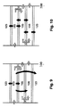
- a high/medium temperature fuel cell system 100 consists usually of a hot and a cold part.
- the hot part 112 (see Fig. 2 ) is thermally insulated and consists typically of the reformer 103, fuel cell 105 and post-combustor unit 106.
- the pretreaters 102, 104 can be totally or partly included.
- the cold part is at about room temperature and the hot part is for a SOFC at around 550°C and higher.
- the battery/capacitor 107, the blower 108, and the fuel container 101 lie in the cold part.
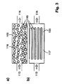
- a typical fuel reformer 103 has at least one inlet 113 and one outlet 114.
- the reactants (fuel and air) enter either premixed or unmixed the reformer 103 at the inlet 113. They are catalytically converted into a product gas that leaves the reformer 103 at the outlet 114.
- the catalytically active substance is usually a noble metal on a ceramic support. It usually lies on beads 116 (see Fig. 3a ) or on the inside of channels 117 or similar structures (see Fig. 3b ).
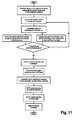
- the start-up is a transient process that brings the whole system from an initial condition to the (e.g. steady state or optimum) operation condition.
- the mass fluxes are zero and the temperature of the hot part is lower than the normal operation temperature. Therefore, the start-up process usually implies an increase of temperature of the hot part of the fuel cell system.
- the whole hot part is heated by an electrical heater in order to reach the optimum operation temperature (see Fig. 4 ) by using a heating coil (Joule heating) for the hot part of the system.
- Fig. 6 The operation scheme during start-up of ISP is schematically shown in Fig. 6 , here the reformer 103 provides the thermal energy to heat up the other components.
- the reformer 103 consists of a catalytically active reaction zone made out of a structure that is itself reactive or that is coated with an active material and an electrically resistive element 122 that can be heated by Joule heating (see Fig. 7 ).
- the catalyst used for the post-combustor is usually: Pt (+ Support) or Pd (+ Support) ⁇ Pt/Pd is known for high total oxidation capability e.g.: C 4 H 10 + 6.5 O 2 ⁇ 4 CO 2 + 5 H 2 O
- the catalyst used for the reformer is usually: Rh (+ Support), seldom Ru/Pt ⁇ Rh is known for high partial oxidation capability e.g.: C 4 H 10 + 2 O 2 ⁇ 4 CO + 5 H 2
- the existing idea as given above and in accordance with the state-of the-art is to heat the fuel cell system 100 by the post-combustor 106, due to its ability to totally oxidize fuel und thus thermal energy generation.
- the reformer 103 is also able to totally oxidize the fuel, it can also be used as a heat generating source at the start-up process.
- exergy unit (ExU) to be heated up from initial temperature to the normal operation temperature.
- CSP1 the whole exergy amount is provided by the battery/capacitor with an assumed efficiency of 1.
- the battery/capacitor must be charged by the fuel cell system under normal operation.
- An exergetic efficiency of 0.19 is realistic leading to a chemical exergy input by the fuel of 5.3 ExU (see Fig. 11 showing the exergy flow scheme of CSP1.
- the numbers correspond to an arbitrary exergy unit, ExU).
- Hot combustion gases In the ISP hot combustion gases directly heat the other units from the inside. Thus, totally oxidized, hot gases leaving the reformer directly enter the other units. In CSP2 the other components are only heated indirectly via a heat exchanger that heats the inflow gases leading to a lower efficiency (see Fig. 12 , showing the gas flow and temperature of (a) ISP and (b) CSP2).
- Coking and deactivation of the fuel cell Coking and other deactivation mechanisms are a serious problem in fuel cell research, because they lower the performance of the fuel cell.
- the fuel/air mixture In the ISP, the fuel/air mixture is completely burnt before the inlet of the fuel cell. Thus, a mixture of CO 2 and H 2 O and air is very unlikely to deactivate the fuel cell.
- the CSP2 unburned or partially burned fuel flows through the fuel cell. The fuel cell temperature rises constantly during the start-up process. It is known that for certain mixtures with carbon contents (other than CO 2 ) and certain temperatures, deactivation of the fuel cell occurs. During start-up, it is likely that at least at one moment the condition inside the fuel cell is in the deactivation regime (see Fig. 13 , showing the gas composition of (a) ISP and (b) CSP2).
- the volume flow of the fuel through the fuel cell system is usually controlled by a valve 129 behind the fuel container 101.
- a valve 129 behind the fuel container 101.
- the valve needs to be adjusted. Since the hottest part of the fuel cell system during start-up is the heat source, the temperature measurement is preferably taken in the reformer for the ISP and in the post-combustor for CSP2.
- the volume of the unreacted gases forms a buffer volume (see Fig. 15 , showing the volume of unreacted gases inside the fuel cell system (a) in the ISP and (b) in CSP2).
- the ISP is easier and faster to control than the CSP2 because its buffer volume is much smaller. Furthermore, small buffer volumes usually lead to higher efficiencies.
- the reactor volume of the post-combustor is estimated as follows:
- the stoichiometric fuel to air ratio inside the fuel cell is high.
- the reformer equivalence ratio, based on partial oxidation is 0.8
- the fuel is butane and that the space time inside the reformer is similar to that of the post-combustor.
- the advantage of the ISP is the smaller volume that needs to be heated up electrically.
- a possible set up for the fuel cell assembly as proposed herein can be built by using concentric quartz tubes in which in a certain section catalyst material is provided and the catalyst section is closed on both ends by a plug material.
- the catalyst material for the re-former can be provided, between the innermost tube and the second tube the catalyst/structure for the fuel cell and/or post-combustor or vice versa.
- Possible dimensions for a micro fuel cell are for example two concentric tubes with wall thickness of about 1 mm and an inner diameter of the inner tube of 1.5 mm and an inner diameter of the outer tube of 5 mm.
- the catalyst section of the reformer can for example have a length of around 10mm for a sufficient reaction area.
- the catalyst used for the experiments was a packed bed (PB) with catalytic nanoparticles.
- PB packed bed
- a catalyst consisting of Rh/Ce 0.5 Zr 0.5 O 2 nano particles was used and SiO 2 was used as supporting material to reduce the pressure drop (weight ratio of 1:3 of these two components within the packed bed).
- Figure 18 shows a schematic view of the SiO 2 sand surrounded by the catalyst nano particles (centre picture) as well as SEM pictures (top pictures) of the particles.
- the catalyst section was closed in both cases by using Al 2 O 3 /SiO 2 fibre plugs as indicated in figure 18 (bottom picture).
- the heat source 132 for the start-up process (reformer, and for comparison post-combustor) is located centrally in the innermost tube and is provided with a resistive heating unit 122 (e.g. Kanthal D wire).
- the fuel/air mixture 131 e.g. butane/air enters this setup in the central tube from the left side and during the start-up phase, when total oxidation (TOX) conditions are maintained, exits the central tube as water and carbon dioxide on the right side.
- the further components 133 of the fuel cell are surrounding this heat source element 132 leading to the heat transfer as indicated by the solid arrows during start up.
- This whole hot area of the fuel cell assembly is surrounded by an insulation 118.
- the fuel/air mixture 131 enters from the left side in the interspace between the innermost tube and the outer tube and the fully oxidated reaction products exit towards the right side.
- the resistive heating unit 122 is provided in the interspace where the heat source 132 is located. The advantage of this second set up is the larger volume available on the outside and the higher possible mass flow.
Landscapes
- Chemical & Material Sciences (AREA)
- Chemical Kinetics & Catalysis (AREA)
- Engineering & Computer Science (AREA)
- General Chemical & Material Sciences (AREA)
- Sustainable Energy (AREA)
- Sustainable Development (AREA)
- Manufacturing & Machinery (AREA)
- Electrochemistry (AREA)
- Life Sciences & Earth Sciences (AREA)
- Organic Chemistry (AREA)
- Combustion & Propulsion (AREA)
- Health & Medical Sciences (AREA)
- General Health & Medical Sciences (AREA)
- Inorganic Chemistry (AREA)
- Hydrogen, Water And Hydrids (AREA)
- Fuel Cell (AREA)
Priority Applications (2)
| Application Number | Priority Date | Filing Date | Title |
|---|---|---|---|
| EP07012131A EP2006945A1 (de) | 2007-06-21 | 2007-06-21 | Verfahren zum Starten einer Brennstoffzellenanordnung |
| PCT/EP2008/004401 WO2008155015A1 (en) | 2007-06-21 | 2008-06-03 | Method for starting up a fuel cell assembly |
Applications Claiming Priority (1)
| Application Number | Priority Date | Filing Date | Title |
|---|---|---|---|
| EP07012131A EP2006945A1 (de) | 2007-06-21 | 2007-06-21 | Verfahren zum Starten einer Brennstoffzellenanordnung |
Publications (1)
| Publication Number | Publication Date |
|---|---|
| EP2006945A1 true EP2006945A1 (de) | 2008-12-24 |
Family
ID=38565893
Family Applications (1)
| Application Number | Title | Priority Date | Filing Date |
|---|---|---|---|
| EP07012131A Withdrawn EP2006945A1 (de) | 2007-06-21 | 2007-06-21 | Verfahren zum Starten einer Brennstoffzellenanordnung |
Country Status (2)
| Country | Link |
|---|---|
| EP (1) | EP2006945A1 (de) |
| WO (1) | WO2008155015A1 (de) |
Cited By (1)
| Publication number | Priority date | Publication date | Assignee | Title |
|---|---|---|---|---|
| KR101751102B1 (ko) | 2014-08-22 | 2017-06-28 | 한양대학교 산학협력단 | 연료전지 시스템 |
Citations (5)
| Publication number | Priority date | Publication date | Assignee | Title |
|---|---|---|---|---|
| DE10142578A1 (de) * | 2001-09-02 | 2003-04-10 | Webasto Thermosysteme Gmbh | System zum Erzeugen elektrischer Energie und Verfahren zum Betreiben eines Systems zum Erzeugen elektrischer Energie |
| EP1408003A1 (de) * | 2002-10-10 | 2004-04-14 | Matsushita Electric Industrial Co., Ltd. | Wasserstofferzeuger und ein denselben verwendenden elektrischer Generator |
| US20040081871A1 (en) * | 2002-10-28 | 2004-04-29 | Kearl Daniel A. | Fuel cell using a catalytic combustor to exchange heat |
| US20050112452A1 (en) * | 2003-10-30 | 2005-05-26 | Crumm Aaron T. | Solid oxide fuel cell tube with internal fuel processing |
| EP1739777A2 (de) * | 2005-06-28 | 2007-01-03 | J. Eberspächer GmbH Co. KG | Brennstoffzellensystem für ein Fahrzeug |
Family Cites Families (2)
| Publication number | Priority date | Publication date | Assignee | Title |
|---|---|---|---|---|
| CA2519340A1 (en) * | 2003-03-17 | 2004-09-30 | Matsushita Electric Industrial Co., Ltd. | Fuel cell |
| DE102005019297A1 (de) * | 2005-04-26 | 2006-11-09 | Mtu Aero Engines Gmbh | Verfahren zur Herstellung von wasserstoffselektiven Lösungs-Diffusionsmembranen |
-
2007
- 2007-06-21 EP EP07012131A patent/EP2006945A1/de not_active Withdrawn
-
2008
- 2008-06-03 WO PCT/EP2008/004401 patent/WO2008155015A1/en active Application Filing
Patent Citations (5)
| Publication number | Priority date | Publication date | Assignee | Title |
|---|---|---|---|---|
| DE10142578A1 (de) * | 2001-09-02 | 2003-04-10 | Webasto Thermosysteme Gmbh | System zum Erzeugen elektrischer Energie und Verfahren zum Betreiben eines Systems zum Erzeugen elektrischer Energie |
| EP1408003A1 (de) * | 2002-10-10 | 2004-04-14 | Matsushita Electric Industrial Co., Ltd. | Wasserstofferzeuger und ein denselben verwendenden elektrischer Generator |
| US20040081871A1 (en) * | 2002-10-28 | 2004-04-29 | Kearl Daniel A. | Fuel cell using a catalytic combustor to exchange heat |
| US20050112452A1 (en) * | 2003-10-30 | 2005-05-26 | Crumm Aaron T. | Solid oxide fuel cell tube with internal fuel processing |
| EP1739777A2 (de) * | 2005-06-28 | 2007-01-03 | J. Eberspächer GmbH Co. KG | Brennstoffzellensystem für ein Fahrzeug |
Non-Patent Citations (2)
| Title |
|---|
| ADAM F. LEE, CHÉ R. SEABOURNE, KAREN WILSON: "Sulphate-promotion and structure-sensitivity in hydrocarbon combustion over Rh/Al2O3 catalysts", CATALYSIS COMMUNICATIONS, vol. 7, no. 8, 9 March 2006 (2006-03-09), pages 566 - 570, XP002454988 * |
| NICO HOTZ, MICHAEL J. STUTZ, STEFAN LOHER, WENDELIN J. STARK, DIMOS POULIKAKOS: "Syngas production from butane using a flame-made Rh/Ce0.5Zr0.5O2 catalyst", APPLIED CATALYSIS B: ENVIRONMENTAL, vol. 73, 12 January 2007 (2007-01-12), pages 336 - 344, XP002454987 * |
Cited By (1)
| Publication number | Priority date | Publication date | Assignee | Title |
|---|---|---|---|---|
| KR101751102B1 (ko) | 2014-08-22 | 2017-06-28 | 한양대학교 산학협력단 | 연료전지 시스템 |
Also Published As
| Publication number | Publication date |
|---|---|
| WO2008155015A1 (en) | 2008-12-24 |
Similar Documents
| Publication | Publication Date | Title |
|---|---|---|
| US8309270B2 (en) | Solid oxide fuel cell systems with improved gas channeling and heat exchange | |
| JP5773240B2 (ja) | 燃料を低酸素ガスおよび/または高水素ガスに転化するためのガス発生器および方法 | |
| JP6204605B2 (ja) | 液体及びガス状の燃料両用の改質器及び改質方法 | |
| AU2001272281B2 (en) | Integrated module for solid oxide fuel cell systems | |
| US7695841B2 (en) | Solid oxide fuel cell tube with internal fuel processing | |
| TWI392543B (zh) | 燃料重組反應物中快速加熱之方法與裝置 | |
| AU2006201057B2 (en) | Reformer fuel cell system with external burner | |
| JP4854037B2 (ja) | 燃料改質装置及びその駆動方法、並びに燃料電池システム | |
| EP3336946B1 (de) | Festoxidbrennstoffzellensystem | |
| EP1148024A1 (de) | Vorrichtung zur herstellung von wasserstoffgas und verwendung dieses gases in einem brennstoffzellensystem | |
| JP2008247727A (ja) | 反応容器および反応装置 | |
| JP2007080761A (ja) | 燃料電池およびその起動方法 | |
| WO2005077820A1 (ja) | 燃料改質装置 | |
| JP2007200709A (ja) | 固体酸化物形燃料電池スタックおよびその運転方法 | |
| EP2006945A1 (de) | Verfahren zum Starten einer Brennstoffzellenanordnung | |
| EP2183811B1 (de) | Festoxid-brennstoffzellensysteme mit verbesserter gaskanalisierung und verbessertem wärmeaustausch | |
| JP5805524B2 (ja) | 改質器及びこれを使用した燃料電池システム | |
| JP2009302010A (ja) | 燃料電池コージェネレーションシステム | |
| EP1231664B1 (de) | Temperatur- und Umsatzkontrollsystem für Brennstoffreformer | |
| JPH11149931A (ja) | 燃料電池用改質装置の起動方法 | |
| RU2447545C2 (ru) | Системы твердооксидных топливных элементов с улучшенными канализированием газов и теплообменом | |
| JP3763092B2 (ja) | 燃料電池用水素製造装置 |
Legal Events
| Date | Code | Title | Description |
|---|---|---|---|
| PUAI | Public reference made under article 153(3) epc to a published international application that has entered the european phase |
Free format text: ORIGINAL CODE: 0009012 |
|
| AK | Designated contracting states |
Kind code of ref document: A1 Designated state(s): AT BE BG CH CY CZ DE DK EE ES FI FR GB GR HU IE IS IT LI LT LU LV MC MT NL PL PT RO SE SI SK TR |
|
| AX | Request for extension of the european patent |
Extension state: AL BA HR MK RS |
|
| AKX | Designation fees paid | ||
| REG | Reference to a national code |
Ref country code: DE Ref legal event code: 8566 |
|
| STAA | Information on the status of an ep patent application or granted ep patent |
Free format text: STATUS: THE APPLICATION IS DEEMED TO BE WITHDRAWN |
|
| 18D | Application deemed to be withdrawn |
Effective date: 20090625 |