EP4120693A1 - Lautsprecher verzerrungskorrektur vorrichtung - Google Patents
Lautsprecher verzerrungskorrektur vorrichtung Download PDFInfo
- Publication number
- EP4120693A1 EP4120693A1 EP22183593.7A EP22183593A EP4120693A1 EP 4120693 A1 EP4120693 A1 EP 4120693A1 EP 22183593 A EP22183593 A EP 22183593A EP 4120693 A1 EP4120693 A1 EP 4120693A1
- Authority
- EP
- European Patent Office
- Prior art keywords
- speaker
- vibration
- input
- relative
- detection unit
- Prior art date
- Legal status (The legal status is an assumption and is not a legal conclusion. Google has not performed a legal analysis and makes no representation as to the accuracy of the status listed.)
- Granted
Links
- 238000012937 correction Methods 0.000 title claims abstract description 52
- 230000003044 adaptive effect Effects 0.000 claims abstract description 34
- 238000012546 transfer Methods 0.000 claims abstract description 33
- 238000001514 detection method Methods 0.000 claims description 41
- 238000010438 heat treatment Methods 0.000 claims description 9
- 230000008014 freezing Effects 0.000 claims description 7
- 238000007710 freezing Methods 0.000 claims description 7
- 230000007257 malfunction Effects 0.000 claims description 7
- 230000007613 environmental effect Effects 0.000 claims description 4
- 229920006395 saturated elastomer Polymers 0.000 claims description 3
- 238000005259 measurement Methods 0.000 abstract description 12
- 238000000034 method Methods 0.000 description 65
- 238000006073 displacement reaction Methods 0.000 description 12
- 230000000694 effects Effects 0.000 description 7
- 238000004364 calculation method Methods 0.000 description 5
- 230000005236 sound signal Effects 0.000 description 4
- 230000032683 aging Effects 0.000 description 3
- 238000010586 diagram Methods 0.000 description 3
- XEEYBQQBJWHFJM-UHFFFAOYSA-N Iron Chemical compound [Fe] XEEYBQQBJWHFJM-UHFFFAOYSA-N 0.000 description 2
- 230000007423 decrease Effects 0.000 description 2
- 230000003247 decreasing effect Effects 0.000 description 2
- 239000000428 dust Substances 0.000 description 2
- 230000004907 flux Effects 0.000 description 2
- 230000001419 dependent effect Effects 0.000 description 1
- 230000020169 heat generation Effects 0.000 description 1
- 229910052742 iron Inorganic materials 0.000 description 1
- 238000004519 manufacturing process Methods 0.000 description 1
- 238000012360 testing method Methods 0.000 description 1
Images


Classifications
-
- H—ELECTRICITY
- H04—ELECTRIC COMMUNICATION TECHNIQUE
- H04R—LOUDSPEAKERS, MICROPHONES, GRAMOPHONE PICK-UPS OR LIKE ACOUSTIC ELECTROMECHANICAL TRANSDUCERS; DEAF-AID SETS; PUBLIC ADDRESS SYSTEMS
- H04R3/00—Circuits for transducers, loudspeakers or microphones
- H04R3/04—Circuits for transducers, loudspeakers or microphones for correcting frequency response
-
- H—ELECTRICITY
- H04—ELECTRIC COMMUNICATION TECHNIQUE
- H04R—LOUDSPEAKERS, MICROPHONES, GRAMOPHONE PICK-UPS OR LIKE ACOUSTIC ELECTROMECHANICAL TRANSDUCERS; DEAF-AID SETS; PUBLIC ADDRESS SYSTEMS
- H04R3/00—Circuits for transducers, loudspeakers or microphones
- H04R3/007—Protection circuits for transducers
-
- H—ELECTRICITY
- H04—ELECTRIC COMMUNICATION TECHNIQUE
- H04R—LOUDSPEAKERS, MICROPHONES, GRAMOPHONE PICK-UPS OR LIKE ACOUSTIC ELECTROMECHANICAL TRANSDUCERS; DEAF-AID SETS; PUBLIC ADDRESS SYSTEMS
- H04R29/00—Monitoring arrangements; Testing arrangements
- H04R29/001—Monitoring arrangements; Testing arrangements for loudspeakers
-
- H—ELECTRICITY
- H04—ELECTRIC COMMUNICATION TECHNIQUE
- H04R—LOUDSPEAKERS, MICROPHONES, GRAMOPHONE PICK-UPS OR LIKE ACOUSTIC ELECTROMECHANICAL TRANSDUCERS; DEAF-AID SETS; PUBLIC ADDRESS SYSTEMS
- H04R3/00—Circuits for transducers, loudspeakers or microphones
-
- H—ELECTRICITY
- H04—ELECTRIC COMMUNICATION TECHNIQUE
- H04R—LOUDSPEAKERS, MICROPHONES, GRAMOPHONE PICK-UPS OR LIKE ACOUSTIC ELECTROMECHANICAL TRANSDUCERS; DEAF-AID SETS; PUBLIC ADDRESS SYSTEMS
- H04R3/00—Circuits for transducers, loudspeakers or microphones
- H04R3/002—Damping circuit arrangements for transducers, e.g. motional feedback circuits
-
- H—ELECTRICITY
- H04—ELECTRIC COMMUNICATION TECHNIQUE
- H04R—LOUDSPEAKERS, MICROPHONES, GRAMOPHONE PICK-UPS OR LIKE ACOUSTIC ELECTROMECHANICAL TRANSDUCERS; DEAF-AID SETS; PUBLIC ADDRESS SYSTEMS
- H04R2499/00—Aspects covered by H04R or H04S not otherwise provided for in their subgroups
- H04R2499/10—General applications
- H04R2499/13—Acoustic transducers and sound field adaptation in vehicles
Definitions
- the present invention relates to a technique that corrects distortion of output from a speaker relative to input.
- a technique that controls driving of a speaker on the basis of an equivalent circuit a technique is also known that corrects a sound signal that drives a speaker to remove distortion of output from the speaker relative to input, on the basis of an equivalent circuit of the speaker ( JP 6522668 B2 ).
- a technique of Motional Feedback is also known that is equipped with a sensor detecting vibration of a diaphragm of a speaker, and according to the vibration detected by the sensor, controls driving of the speaker (e.g., JP 2008-228214 A and JP 2010-124026 A ).
- an adaptive filter is applied to the correction of a sound signal, and coefficients of the adaptive filter are updated to minimize an error that is the difference between an ideal vibration and detected vibration to remove distortion of the speaker.
- characteristics of a speaker include linear characteristics and nonlinear characteristics.
- Bl, KMS, Le(x, i), and the like represent nonlinear characteristics.
- Fig. 7 is an equivalent circuit illustrated in the above-described "Modeling the large signal behavior of micro-speakers", 133rd Audio Engineering Society Convention 2012, Paper Number 8749, October 25, 2012, written by Klippel, Wolfgang .
- a nonlinear-distortion correction filter that corrects distortion due to nonlinear characteristics of a speaker is provided at a stage before an adaptive filter, and distortion due to linear characteristics of the speaker is corrected with the adaptive filter while transfer characteristics of the nonlinear-distortion correction filter are updated according to the variation in the nonlinear characteristics of the speaker estimated from the variation in the environment, such as a temperature, and the behavior of the speaker.
- an object of the present invention is to restrict the occurrence of the unusual operation while appropriately correcting distortion of a speaker with a relatively simple configuration.
- the invention relates to a speaker distortion correction device and a speaker unit according to the appended claims. Embodiments are disclosed in the dependent claims.
- An aspect of the present invention provides a speaker distortion correction device for correcting distortion of output from a speaker relative to an input signal
- the speaker distortion correction device including: a vibration detection unit configured to detect vibration of a vibration system of the speaker; a variable filter into which the input signal is input and configured to output an output signal that drives the speaker; an adaptive-algorithm execution unit configured to execute a predetermined adaptive algorithm to perform an adaptive operation that updates a transfer characteristic of the variable filter so that vibration detected by the vibration detection unit becomes vibration without distortion relative to the input signal; and a control unit.
- control unit is configured to determine whether or not an amplitude of vibration detected by the vibration detection unit is deviated from a range considered normal relative to a level of an output signal output by the variable filter, and when the amplitude of the vibration detected by the vibration detection unit is deviated from the range considered normal relative to the level of the output signal output by the variable filter, stop an update on the transfer characteristic of the variable filter updated by the adaptive operation of the adaptive-algorithm execution unit.
- a speaker distortion correction device for correcting distortion of output from a speaker relative to an input signal
- the speaker distortion correction device including: a vibration detection unit configured to detect vibration of a vibration system of the speaker; a nonlinear-portion correction filter into which the input signal is input; a variable filter into which output from the nonlinear-portion correction filter is input, the variable filter being configured to output an output signal that drives the speaker; an adaptive-algorithm execution unit configured to execute a predetermined adaptive algorithm to perform an adaptive operation that updates a transfer characteristic of the variable filter so that vibration detected by the vibration detection unit becomes vibration without distortion relative to the input signal; and a control unit.
- a transfer characteristic is set for the nonlinear-portion correction filter, in which the transfer characteristic corrects distortion of output from the speaker relative to the input signal due to a nonlinear characteristic of the speaker.
- the control unit is configured to determine whether or not the amplitude of vibration detected by the vibration detection unit is deviated from a range considered normal relative to a level of an output signal output by the variable filter, and when the amplitude of the vibration detected by the vibration detection unit is deviated from the range considered normal relative to the level of the output signal output by the variable filter, stop an update on the transfer characteristic of the variable filter updated by the adaptive operation of the adaptive-algorithm execution unit.
- the speaker distortion correction device may be configured such that the control unit is configured to, when the amplitude of vibration detected by the vibration detection unit is deviated from, in an excess direction, from the range considered normal, check whether or not a center of the amplitude of the vibration detected by the vibration detection unit is positionally deviated from a defined center position, when the center is positionally deviated from the defined center position, estimate stiffness of the vibration system of the speaker, from an input voltage input into the speaker, an input electric current input into the speaker, and the vibration detected by the vibration detection unit, and when the estimated stiffness is smaller than a defined stiffness range, estimate occurrence of a mechanical malfunction of the vibration system of the speaker.
- the speaker distortion correction device may further include an amplifier configured to drive the speaker by an output signal output by the variable filter
- the control unit may be configured to, when the amplitude of vibration detected by the vibration detection unit is deviated from, in the excess direction, from the range considered normal, and a center of the amplitude of the vibration detected by the vibration detection unit is not positionally deviated from the defined center position, estimate a relationship between stiffness of the vibration system of the speaker and a positional deviation of the vibration system, from an input voltage input into the speaker, an input electric current input into the speaker, and the vibration detected by the vibration detection unit, when in the estimated relationship, a variation in the stiffness relative to the positional deviation of the vibration system is gentle, check whether or not the input electric current input into the speaker relative to the input voltage input into the speaker is smaller than a defined magnitude, and when the input electric current input into the speaker relative to the input voltage input into the speaker is smaller than the defined magnitude, estimate occurrence of a heating unusualness of the speaker.
- the speaker distortion correction device may be configured such that the control unit is configured to, when the amplitude of vibration detected by the vibration detection unit is deviated, in an insufficiency direction, from the range considered normal, determine whether or not clipping within an allowable vibration range has occurred, the clipping within the allowable vibration range being a phenomenon in which a peak portion of waveform of the vibration detected by the vibration detection unit does not reach an upper or lower limit of the allowable vibration range of the vibration system of the speaker and is saturated and deformed at a fixed level, and when clipping has occurred, estimate occurrence of an unusualness that the vibration of the vibration system of the speaker is obstructed by an external object.
- the speaker distortion correction device may further include an amplifier configured to drive the speaker by an output signal output by the variable filter
- the control unit may be configured to, when the amplitude of vibration detected by the vibration detection unit is deviated, in the insufficiency direction, from the range considered normal and clipping within the allowable vibration range has not occurred, estimate a relationship between stiffness of the vibration system of the speaker and a positional deviation of the vibration system, from an input voltage input into the speaker, an input electric current input into the speaker, and the vibration detected by the vibration detection unit, when in the estimated relationship, a variation in the stiffness relative to the positional deviation of the vibration system is steep, check whether or not the input electric current input into the speaker relative to the input voltage input into the speaker is larger than a defined magnitude, and when the input electric current input into the speaker relative to the input voltage input into the speaker is larger than the defined magnitude, estimate occurrence of a heating unusualness of the speaker.
- control unit may be configured to, when the amplitude of vibration detected by the vibration detection unit is deviated, in the insufficiency direction, from the range considered normal, clipping within the allowable vibration range has not occurred, a variation in stiffness of the vibration system of the speaker relative to a positional deviation of the vibration system is steep, and an input electric current input into the speaker relative to an input voltage input into the speaker is not larger than the defined magnitude, check whether or not an environmental temperature is lower than a predetermined temperature, and when the environmental temperature is lower than the predetermined temperature, estimate occurrence of a freezing unusualness of the speaker.
- the above speaker distortion correction device and the speaker may be integrated together to constitute a speaker unit.
- the speaker distortion correction device and speaker unit as described herein, when an unusualness of measured vibration of the vibration system of the speaker occurs, an adaptive operation of an adaptive filter is stopped, and the occurrence of an unusual operation, such as the occurrence of an unpleasant sound, is restricted even when distortion of the speaker is corrected with a relatively simple configuration in which the nonlinear-portion correction filter is provided at a stage before the adaptive filter, and the adaptive filter is used to correct only distortion due to linear characteristics of the speaker. Further, since the measured vibration of the vibration system of the speaker is used to estimate the cause of an unusualness that has occurred, the estimated cause is appropriately dealt with.
- the occurrence of an unusual operation is restricted while distortion of a speaker is appropriately corrected with a relatively simple configuration.
- Fig. 1 illustrates a configuration of the audio system according to an embodiment.
- the audio system includes a control unit 1, a speaker 2, a vibration measurement unit 3 that measures vibration/displacement of a vibration system of the speaker 2, a signal correction unit 4 that outputs an output signal So, an amplifier 5 into which the output signal So is input and that is for driving the speaker 2, and an audio device 6 that outputs an input signal Si that is a sound signal.
- the signal correction unit 4 corrects an input signal Si output by the audio device 6, and outputs the corrected input signal Si as an output signal So.
- the amplifier 5 converts the output signal So into an analog signal (voltage signal), amplifies the analog signal (voltage signal), and drives the speaker 2.
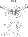
- Fig. 2 illustrates an embodiment of a configuration of the speaker 2.
- the speaker 2 includes a yoke 201, a magnet 202, a top plate 203, a voice coil bobbin 204, a voice coil 205, a frame 206, a damper 207, a diaphragm 208, an edge 209, a dust cap 210, a displacement detection magnet 211, and a magnetic angle sensor 212.
- the yoke 201 has a protrusion 2011 that protrudes forward at the center of the yoke 201.
- the magnet 202 that is annular is provided around an outer periphery portion of the protrusion 2011.
- the top plate 203 that is annular is provided on the magnet 202.
- the top plate 203 is constituted by a conductive member, such as iron.
- the voice coil bobbin 204 has a hollow cylindrical shape.
- the voice coil 205 to which signals are applied from the amplifier 5 is wound around the outer periphery of the voice coil bobbin 204.
- the protrusion 2011 of the yoke 201 is inserted in the hollow of the voice coil bobbin 204 from behind such that the voice coil bobbin 204 can move forward and backward relative to the yoke 201.
- the voice coil 205 is positioned between the protrusion 2011 of the yoke 201 and the top plate 203, at a position where magnetic flux generated between inner-periphery ends of the top plate 203 by the magnetic circuit 220 passes through.
- the diaphragm 208 has a shape similar to the lateral side of a conical frustum whose height direction substantially is a front-back direction of the front speaker.
- the outer-periphery end of the diaphragm 208 is coupled to the front end of the frame 206 by the edge 209.
- the inner-periphery end of the diaphragm 208 is fixed to the front end of the voice coil bobbin 204.
- the displacement detection magnet 211 is fixed to the voice coil bobbin 204 to move upward and downward with the voice coil bobbin 204.
- the magnetic angle sensor 212 is fixed on the top plate 203 or the like so that the position of the magnetic angle sensor 212 does not vary relative to the magnetic circuit 220.
- the magnetic angle sensor 212 detects and outputs the angle of a synthetic vector of a magnetic-flux vector generated by the magnetic circuit 220 and a magnetic-flux vector generated by the displacement detection magnet 211. Due to displacement of the displacement detection magnet 211 that accompanies displacement of the voice coil bobbin 204, the magnetic-flux vector generated by the displacement detection magnet 211 seen from the magnetic angle sensor 212 varies. Therefore, the angle of the synthetic vector represents the displacement amount of the voice coil bobbin 204.
- the vibration measurement unit 3 in Fig. 1 measures the vibration/displacement of the vibration system, such as the voice coil bobbin 204 and the diaphragm 208, of the speaker 2.
- information such as the temperature in the automobile interior, and an aging time of the audio system (the manufacture year, a current time, and the like), is input into the control unit 1, as external information. Further, information about a playing state, such as music being played/no music being played, and an audio source (radio/compact disc (CD) or the like) that is outputting an input signal Si, and information, such as an output level (volume or the like), are input into the control unit 1 from the audio device 6. Further, information about an input voltage and an input electric current is input into the control unit 1 from the speaker 2.
- the signal correction unit 4 includes a nonlinear-portion correction filter 41, a linear inverse filter 42, an adaptive-algorithm execution unit 43, and an error calculation unit 44.
- An input signal Si output by the audio device 6 passes through the nonlinear-portion correction filter 41, is input, as an intermediate corrected signal Sm, into the linear inverse filter 42, passes through the linear inverse filter 42, and is output, as an output signal So, into the speaker 2 through the amplifier 5.
- Transfer characteristics (filter coefficients) of the nonlinear-portion correction filter 41 are switchable from the control unit 1.
- the control unit 1 sets the transfer characteristics of the nonlinear-portion correction filter 41, to transfer characteristics that eliminate distortion of output from the speaker 2 relative to an input signal Si due to nonlinear characteristics of the speaker 2 when the speaker 2 is driven by an intermediate corrected signal Sm output by the nonlinear-portion correction filter 41, that is to say, transfer characteristics that correct distortion due to the nonlinear characteristics of the speaker 2.
- the error calculation unit 44 calculates a difference between vibration of the speaker 2 without the distortion relative to an input signal Si and actual vibration of the speaker 2 measured by the vibration measurement unit 3.
- the linear inverse filter 42 is a variable filter.
- the adaptive-algorithm execution unit 43 and the linear inverse filter 42 constitute an adaptive filter. With an intermediate corrected signal Sm as a reference signal r, and a difference, as an error e, calculated by the error calculation unit 44, the adaptive-algorithm execution unit 43 performs an adaptive operation that updates transfer characteristics (filter coefficients) of the linear inverse filter 42, using a least mean squares (LMS) algorithm or the like, to minimize the error e.
- LMS least mean squares
- control unit 1 estimates current nonlinear characteristics of the speaker 2.
- control unit 1 performs a process of updating the transfer characteristics of the nonlinear-portion correction filter 41 so that the variation is followed.
- nonlinear characteristics at a time of each combination of a temperature in the automobile interior, an aging time of the audio system, and an output level of the audio device 6 are preliminarily determined and stored as a library, and nonlinear characteristics that correspond to a current environment are estimated from the library, as current nonlinear characteristics of the speaker 2.
- a behavior of the speaker 2 relative to input is calculated from vibration of the speaker 2 measured by the vibration measurement unit 3. From the calculated behavior, current nonlinear characteristics of the speaker 2 are estimated.
- the transfer characteristics of the nonlinear-portion correction filter 41 are switched to transfer characteristics that correspond to the estimated current nonlinear characteristics of the speaker 2.
- the transfer characteristics that correspond to the nonlinear characteristics are transfer characteristics that correct distortion due to the nonlinear characteristics.
- a speaker model that reflects estimated nonlinear characteristics may be used to calculate corresponding transfer characteristics.
- transfer characteristics that correspond to each set of nonlinear characteristics may be preliminarily determined and stored to calculate transfer characteristics that correspond to estimated nonlinear characteristics.
- transfer characteristics that correspond to nonlinear characteristics at a time of each combination of a temperature in the automobile interior, an aging time of the audio system, and an output level of the audio device 6 may be preliminarily determined and stored as a library, transfer characteristics that correspond to current nonlinear characteristics of the speaker 2 may be selected from the library, and the transfer characteristics of the nonlinear-portion correction filter 41 may be switched to the selected transfer characteristics.
- Fig. 3 illustrates an embodiment of a procedure of the adaptive-operation control process.
- the control unit 1 determines whether or not the amplitude of vibration measured by the vibration measurement unit 3 is deviated from a defined range that is a range considered normal relative to the level of an output signal So from the linear inverse filter 42 (step 302).
- the level of an output signal So from the linear inverse filter 42 may be directly detected, or may be estimated from the level of output from the audio device 6 or the nonlinear-portion correction filter 41, an input voltage input into the speaker 2, or the like.
- step 306 it is determined whether the amplitude of the vibration is deviated, in an excess direction, from the defined range, or is deviated, in an insufficiency direction, from the defined range.
- step 308 an excessive-amplitude error process is executed (step 308), and the adaptive-operation control process is ended.
- step 302 it is determined that the amplitude of the vibration does not deviate from the defined range, it is checked whether or not an adaptive operation of the adaptive-algorithm execution unit 43 is currently stopped (step 312). When an adaptive operation of the adaptive-algorithm execution unit 43 is not stopped, the adaptive-operation control process is intactly ended.
- step 312 when an adaptive operation of the adaptive-algorithm execution unit 43 is currently stopped (step 312), the adaptive operation of the adaptive-algorithm execution unit 43 is restarted (step 314), the update on the transfer characteristics of the linear inverse filter 42 is restarted, and the adaptive-operation control process is ended.
- step 308 the excessive-amplitude error process performed in step 308 and the insufficient-amplitude error process performed in step 310 of the adaptive-operation control process will be described.
- Fig. 4 illustrates an embodiment of a procedure of the excessive-amplitude error process.
- the control unit 1 checks whether or not the center of an amplitude of vibration measured by the vibration measurement unit 3 is positionally deviated (shifted) from a normal position by a predetermined level or larger (step 402).
- step 402 it is determined that the center of the amplitude of the vibration is positionally deviated from the normal position by the predetermined level or larger, it is checked whether or not Kms(x) is entirely smaller than a standard value (step 410).
- So such as a test signal, a music signal, or an audio watermark signal
- the curve of Kms(x) is, for example, a Kms(x) curve B that entirely has values smaller than a standard Kms(x) curve A illustrated in Fig. 6 , it is determined that the current Kms(x) curve is entirely smaller than the standard values.
- step 408 an error message that informs to the effect that there is a possibility that an unusualness occurs at the speaker 2 is displayed or output by a sound.
- step 412 an error message that informs to the effect that there is a possibility that the damper 207 or the edge 209 of the speaker 2 malfunctions is displayed or output by a sound.
- step 402 when the center of the amplitude of the vibration is not positionally deviated (step 402), it is checked whether or not a current Kms(x) (stiffness) curve of the equivalent circuit of the speaker 2 is gentler than a standard Kms(x) curve preliminarily set (step 404).
- step 404 when the curve of calculated Kms(x) is, for example, a Kms(x) curve C that has a curve gentler than the standard Kms(x) curve A illustrated in Fig. 6 , it is determined in step 404 that the current Kms(x) curve is gentler than the standard Kms(x) curve.
- step 404 it is determined that a current Kms(x) curve is not gentler than the standard Kms(x) curve, the general-error process is performed (step 408), and the excessive-amplitude error process is ended.
- step 406 it is determined that the magnitude of an input electric current input into the speaker 2 relative to an input voltage input into the speaker 2 is smaller than the defined magnitude, a voice coil heating error process is performed, considering a possibility that the voice coil 205 is heated due to the increase in the resistance of the speaker 2 (step 414), and the excessive-amplitude error process is ended.
- step 414 an error message that informs to the effect that there is a possibility that the voice coil 205 is heated is displayed or output by a sound, and a process of decreasing the gain of the amplifier 5 to restrict the heat generation is performed.
- Fig. 5 illustrates an embodiment of a procedure of the insufficient-amplitude error process.
- the control unit 1 checks whether or not, in vibration measured by the vibration measurement unit 3, clipping within the allowable vibration range has occurred (step 502).
- the clipping within the allowable vibration range is a phenomenon in which peak portions of the vibration waveform do not reach an upper or lower limit of the allowable vibration range and are saturated and deformed at a fixed level.
- step 502 it is determined that clipping within the allowable vibration range occurs, an object-contact-obstructed-vibration error process is performed (step 512), and the insufficient-amplitude error process is ended.
- an error message that informs to the effect that there is a possibility that an unusualness due to object contact occurs at the speaker 2 is displayed or output by a sound, and a process of decreasing the gain of the amplifier 5 is performed to make peaks of vibration of the vibration system of the speaker 2 smaller than the level at which the saturation of the vibration waveform occurs.
- step 502 when clipping within the allowable vibration range has not occurred (step 502), it is checked whether or not a current Kms(x) curve of the equivalent circuit of the speaker 2 is steeper than a standard Kms(x) curve preliminarily set (step 504).
- the curve of Kms(x) is, for example, a Kms(x) curve D that has a curve steeper than the standard Kms(x) curve A illustrated in Fig. 6 , it is determined that the current Kms(x) curve is steeper than the standard Kms(x) curve.
- step 504 it is not determined that a current Kms(x) curve of the equivalent circuit of the speaker 2 is steeper than the standard Kms(x) curve preliminarily set, a general-error process is performed (step 510), and the insufficient-amplitude error process is ended.
- step 510 an error message that informs to the effect that there is a possibility that an unusualness occurs at the speaker 2 is displayed or output by a sound.
- step 504 when it is determined that a current Kms(x) curve is steeper than the standard Kms(x) curve (step 504), the fact indicates that the vibration system of the speaker 2 is less likely to be displaced relative to an input voltage input into the speaker 2. Therefore, it is checked whether or not the magnitude of an input electric current input into the speaker 2 relative to an input voltage input into the speaker 2 is larger than a defined magnitude by a predetermined level or larger, that is to say, whether or not the resistance of the speaker 2 decreases (step 506).
- step 506 it is determined that the magnitude of an input electric current input into the speaker 2 relative to an input voltage input into the speaker 2 is larger than the defined magnitude by the predetermined level or larger, a voice coil overcurrent heating error process is performed (step 514), and the insufficient-amplitude error process is ended.
- step 514 an error message that informs to the effect that there is a possibility that a malfunction due to short circuit occurs at the speaker 2 is displayed or output by a sound, and operation of the amplifier 5 is stopped.
- step 506 when the magnitude of an input electric current input into the speaker 2 relative to an input voltage input into the speaker 2 is not larger than the defined magnitude by the predetermined level or larger (step 506), it is checked whether or not the temperature in the automobile interior is an extremely low temperature to the degree at which freezing occurs (step 508). When the temperature in the automobile interior is not an extremely low temperature, the general-error process is performed (step 510), and the insufficient-amplitude error process is ended.
- step 508 it is determined that the temperature in the automobile interior is an extremely low temperature, a freezing error process is performed (step 516), and the insufficient-amplitude error process is ended.
- step 516 an error message that informs to the effect that there is a possibility that freezing occurs at the speaker 2 is displayed or output by a sound.
- an adaptive operation of the adaptive filter is stopped, and the occurrence of an unusual operation, such as the occurrence of an unpleasant sound, is restricted while distortion of the speaker 2 is appropriately corrected with a relatively simple configuration in which the nonlinear-portion correction filter 41 is provided at a stage before the adaptive filter, and the adaptive filter is used to correct only distortion due to linear characteristics of the speaker 2. Further, the measured vibration of the vibration system of the speaker 2 is used to estimate the cause of an unusualness that has occurred, and the estimated cause is appropriately dealt with.
- the nonlinear-portion correction filter 41 may not be provided, and an input signal Si may be directly input into the linear inverse filter 42. Even in such a case, due to the processes in Figs. 3 , 4 , and 5 , the occurrence of an unusual operation, such as the occurrence of an unpleasant sound, is restricted, the cause of an unusualness that has occurred is estimated, and the estimated cause is appropriately dealt with.
- the speaker 2, the vibration measurement unit 3, and the signal correction unit 4 may be integrated together as a speaker unit.
Landscapes
- Physics & Mathematics (AREA)
- Engineering & Computer Science (AREA)
- Acoustics & Sound (AREA)
- Signal Processing (AREA)
- Health & Medical Sciences (AREA)
- General Health & Medical Sciences (AREA)
- Otolaryngology (AREA)
- Circuit For Audible Band Transducer (AREA)
Applications Claiming Priority (1)
| Application Number | Priority Date | Filing Date | Title |
|---|---|---|---|
| JP2021117549A JP2023013398A (ja) | 2021-07-16 | 2021-07-16 | スピーカの歪み補正装置及びスピーカユニット |
Publications (2)
| Publication Number | Publication Date |
|---|---|
| EP4120693A1 true EP4120693A1 (de) | 2023-01-18 |
| EP4120693B1 EP4120693B1 (de) | 2024-04-10 |
Family
ID=82403572
Family Applications (1)
| Application Number | Title | Priority Date | Filing Date |
|---|---|---|---|
| EP22183593.7A Active EP4120693B1 (de) | 2021-07-16 | 2022-07-07 | Lautsprecherverzerrungskorrekturvorrichtung |
Country Status (4)
| Country | Link |
|---|---|
| US (1) | US20230012785A1 (de) |
| EP (1) | EP4120693B1 (de) |
| JP (1) | JP2023013398A (de) |
| CN (1) | CN115623404A (de) |
Citations (7)
| Publication number | Priority date | Publication date | Assignee | Title |
|---|---|---|---|---|
| JPH0222668B2 (de) | 1984-10-15 | 1990-05-21 | Matsushita Electric Works Ltd | |
| JPH0784584A (ja) * | 1993-09-14 | 1995-03-31 | Matsushita Electric Ind Co Ltd | 消音装置 |
| JP2007081815A (ja) * | 2005-09-14 | 2007-03-29 | Matsushita Electric Ind Co Ltd | スピーカ装置 |
| JP2008228214A (ja) | 2007-03-15 | 2008-09-25 | Funai Electric Co Ltd | スピーカ装置 |
| JP2010124026A (ja) | 2008-11-17 | 2010-06-03 | Nidec Pigeon Corp | スピーカ |
| WO2017179539A1 (ja) | 2016-04-12 | 2017-10-19 | 株式会社 Trigence Semiconductor | スピーカ駆動装置、スピーカ装置およびプログラム |
| US20210204043A1 (en) * | 2019-12-30 | 2021-07-01 | Harman Becker Automotive Systems Gmbh | System and method for adaptive control of online extraction of loudspeaker parameters |
Family Cites Families (4)
| Publication number | Priority date | Publication date | Assignee | Title |
|---|---|---|---|---|
| US10200000B2 (en) * | 2012-03-27 | 2019-02-05 | Htc Corporation | Handheld electronic apparatus, sound producing system and control method of sound producing thereof |
| US9432771B2 (en) * | 2013-09-20 | 2016-08-30 | Cirrus Logic, Inc. | Systems and methods for protecting a speaker from overexcursion |
| US11184705B2 (en) * | 2019-11-01 | 2021-11-23 | Synaptics Incorporated | Protection of speaker from excess excursion |
| JP7369948B2 (ja) * | 2019-11-19 | 2023-10-27 | パナソニックIpマネジメント株式会社 | 能動騒音低減装置、移動体装置、及び、能動騒音低減方法 |
-
2021
- 2021-07-16 JP JP2021117549A patent/JP2023013398A/ja active Pending
-
2022
- 2022-07-07 EP EP22183593.7A patent/EP4120693B1/de active Active
- 2022-07-08 US US17/860,861 patent/US20230012785A1/en active Pending
- 2022-07-08 CN CN202210815305.2A patent/CN115623404A/zh active Pending
Patent Citations (7)
| Publication number | Priority date | Publication date | Assignee | Title |
|---|---|---|---|---|
| JPH0222668B2 (de) | 1984-10-15 | 1990-05-21 | Matsushita Electric Works Ltd | |
| JPH0784584A (ja) * | 1993-09-14 | 1995-03-31 | Matsushita Electric Ind Co Ltd | 消音装置 |
| JP2007081815A (ja) * | 2005-09-14 | 2007-03-29 | Matsushita Electric Ind Co Ltd | スピーカ装置 |
| JP2008228214A (ja) | 2007-03-15 | 2008-09-25 | Funai Electric Co Ltd | スピーカ装置 |
| JP2010124026A (ja) | 2008-11-17 | 2010-06-03 | Nidec Pigeon Corp | スピーカ |
| WO2017179539A1 (ja) | 2016-04-12 | 2017-10-19 | 株式会社 Trigence Semiconductor | スピーカ駆動装置、スピーカ装置およびプログラム |
| US20210204043A1 (en) * | 2019-12-30 | 2021-07-01 | Harman Becker Automotive Systems Gmbh | System and method for adaptive control of online extraction of loudspeaker parameters |
Non-Patent Citations (1)
| Title |
|---|
| KLIPPELWOLFGANG: "Modeling the large signal behavior of micro-speakers", 133RD AUDIO ENGINEERING SOCIETY CONVENTION 2012, 25 October 2012 (2012-10-25) |
Also Published As
| Publication number | Publication date |
|---|---|
| JP2023013398A (ja) | 2023-01-26 |
| US20230012785A1 (en) | 2023-01-19 |
| EP4120693B1 (de) | 2024-04-10 |
| CN115623404A (zh) | 2023-01-17 |
Similar Documents
| Publication | Publication Date | Title |
|---|---|---|
| US10734959B2 (en) | Sound processing device and method to suppress an excessive amplitude | |
| US8073149B2 (en) | Loudspeaker device | |
| EP3021597B1 (de) | System und verfahren zur schätzung der bewegung eines lautsprecherkonus | |
| US9838794B2 (en) | Double coil speaker | |
| KR101647315B1 (ko) | 입력 신호를 출력 신호로 변환하고 입력 신호와 출력 신호 사이에서 기설정된 전달 반응을 생성하는 장치 및 방법 | |
| EP2026326A1 (de) | System zur aktiven rauschunterdrückung | |
| US20200275206A1 (en) | Loudspeaker enhancement | |
| EP2929700B1 (de) | Akustischer wandler | |
| WO2014019717A1 (en) | Electroacoustic driver | |
| EP4120693A1 (de) | Lautsprecher verzerrungskorrektur vorrichtung | |
| US20030118193A1 (en) | Method and system for digitally controlling a speaker | |
| JP2006197206A (ja) | スピーカ装置 | |
| CN109951787B (zh) | 扩音器参数预测系统 | |
| JP2023125746A (ja) | スピーカの歪み補正装置及びスピーカユニット | |
| US20060029238A1 (en) | Device and method for driving speaker | |
| CN113993041A (zh) | 宽带扬声器及其控制方法 | |
| KR101800575B1 (ko) | 외부 환경을 이용한 고성능 트랜스듀서 | |
| JP2022143855A (ja) | スピーカの歪み補正装置及びスピーカユニット | |
| JP2012134687A (ja) | 音響システム | |
| EP4325889A1 (de) | Audiosystem | |
| KR102663024B1 (ko) | 진동스피커 및 그 제어방법 | |
| JP6997478B1 (ja) | アンプ装置、オーディオ装置、及びアンプ装置の制御方法 | |
| US20240137698A1 (en) | Speaker output characteristic correction system and sound system | |
| US20240187793A1 (en) | Speaker | |
| JP2021175058A (ja) | スピーカユニット、スピーカ装置、制御方法、プログラム |
Legal Events
| Date | Code | Title | Description |
|---|---|---|---|
| PUAI | Public reference made under article 153(3) epc to a published international application that has entered the european phase |
Free format text: ORIGINAL CODE: 0009012 |
|
| STAA | Information on the status of an ep patent application or granted ep patent |
Free format text: STATUS: THE APPLICATION HAS BEEN PUBLISHED |
|
| AK | Designated contracting states |
Kind code of ref document: A1 Designated state(s): AL AT BE BG CH CY CZ DE DK EE ES FI FR GB GR HR HU IE IS IT LI LT LU LV MC MK MT NL NO PL PT RO RS SE SI SK SM TR |
|
| STAA | Information on the status of an ep patent application or granted ep patent |
Free format text: STATUS: REQUEST FOR EXAMINATION WAS MADE |
|
| 17P | Request for examination filed |
Effective date: 20230703 |
|
| RBV | Designated contracting states (corrected) |
Designated state(s): AL AT BE BG CH CY CZ DE DK EE ES FI FR GB GR HR HU IE IS IT LI LT LU LV MC MK MT NL NO PL PT RO RS SE SI SK SM TR |
|
| GRAJ | Information related to disapproval of communication of intention to grant by the applicant or resumption of examination proceedings by the epo deleted |
Free format text: ORIGINAL CODE: EPIDOSDIGR1 |
|
| STAA | Information on the status of an ep patent application or granted ep patent |
Free format text: STATUS: GRANT OF PATENT IS INTENDED |
|
| GRAP | Despatch of communication of intention to grant a patent |
Free format text: ORIGINAL CODE: EPIDOSNIGR1 |
|
| RIC1 | Information provided on ipc code assigned before grant |
Ipc: H04R 29/00 20060101ALI20231102BHEP Ipc: H04R 3/00 20060101ALI20231102BHEP Ipc: H04R 3/04 20060101AFI20231102BHEP |
|
| INTG | Intention to grant announced |
Effective date: 20231117 |
|
| RAP3 | Party data changed (applicant data changed or rights of an application transferred) |
Owner name: ALPS ALPINE CO., LTD. |
|
| GRAS | Grant fee paid |
Free format text: ORIGINAL CODE: EPIDOSNIGR3 |
|
| GRAA | (expected) grant |
Free format text: ORIGINAL CODE: 0009210 |
|
| STAA | Information on the status of an ep patent application or granted ep patent |
Free format text: STATUS: THE PATENT HAS BEEN GRANTED |
|
| AK | Designated contracting states |
Kind code of ref document: B1 Designated state(s): AL AT BE BG CH CY CZ DE DK EE ES FI FR GB GR HR HU IE IS IT LI LT LU LV MC MK MT NL NO PL PT RO RS SE SI SK SM TR |
|
| REG | Reference to a national code |
Ref country code: GB Ref legal event code: FG4D |
|
| REG | Reference to a national code |
Ref country code: CH Ref legal event code: EP |
|
| P01 | Opt-out of the competence of the unified patent court (upc) registered |
Effective date: 20240315 |
|
| REG | Reference to a national code |
Ref country code: DE Ref legal event code: R096 Ref document number: 602022002796 Country of ref document: DE |
|
| REG | Reference to a national code |
Ref country code: IE Ref legal event code: FG4D |