EP4119756A1 - Türbetätiger-brandschutzanordnung - Google Patents
Türbetätiger-brandschutzanordnung Download PDFInfo
- Publication number
- EP4119756A1 EP4119756A1 EP21185318.9A EP21185318A EP4119756A1 EP 4119756 A1 EP4119756 A1 EP 4119756A1 EP 21185318 A EP21185318 A EP 21185318A EP 4119756 A1 EP4119756 A1 EP 4119756A1
- Authority
- EP
- European Patent Office
- Prior art keywords
- door
- box
- door operator
- fire protection
- protection arrangement
- Prior art date
- Legal status (The legal status is an assumption and is not a legal conclusion. Google has not performed a legal analysis and makes no representation as to the accuracy of the status listed.)
- Withdrawn
Links
- 239000011230 binding agent Substances 0.000 claims description 4
- 239000000463 material Substances 0.000 claims description 4
- 239000003921 oil Substances 0.000 description 9
- QVGXLLKOCUKJST-UHFFFAOYSA-N atomic oxygen Chemical compound [O] QVGXLLKOCUKJST-UHFFFAOYSA-N 0.000 description 4
- 239000012530 fluid Substances 0.000 description 4
- 239000001301 oxygen Substances 0.000 description 4
- 229910052760 oxygen Inorganic materials 0.000 description 4
- 238000005538 encapsulation Methods 0.000 description 3
- 238000007789 sealing Methods 0.000 description 3
- 238000010276 construction Methods 0.000 description 2
- 239000007789 gas Substances 0.000 description 2
- 229910052751 metal Inorganic materials 0.000 description 2
- 239000002184 metal Substances 0.000 description 2
- 239000000853 adhesive Substances 0.000 description 1
- 238000004026 adhesive bonding Methods 0.000 description 1
- 230000001070 adhesive effect Effects 0.000 description 1
- 229910052782 aluminium Inorganic materials 0.000 description 1
- XAGFODPZIPBFFR-UHFFFAOYSA-N aluminium Chemical compound [Al] XAGFODPZIPBFFR-UHFFFAOYSA-N 0.000 description 1
- 230000001419 dependent effect Effects 0.000 description 1
- 230000000694 effects Effects 0.000 description 1
- 230000005662 electromechanics Effects 0.000 description 1
- 239000010720 hydraulic oil Substances 0.000 description 1
- 230000002093 peripheral effect Effects 0.000 description 1
- 238000009420 retrofitting Methods 0.000 description 1
Images



Classifications
-
- E—FIXED CONSTRUCTIONS
- E05—LOCKS; KEYS; WINDOW OR DOOR FITTINGS; SAFES
- E05F—DEVICES FOR MOVING WINGS INTO OPEN OR CLOSED POSITION; CHECKS FOR WINGS; WING FITTINGS NOT OTHERWISE PROVIDED FOR, CONCERNED WITH THE FUNCTIONING OF THE WING
- E05F3/00—Closers or openers with braking devices, e.g. checks; Construction of pneumatic or liquid braking devices
- E05F3/04—Closers or openers with braking devices, e.g. checks; Construction of pneumatic or liquid braking devices with liquid piston brakes
-
- E—FIXED CONSTRUCTIONS
- E05—LOCKS; KEYS; WINDOW OR DOOR FITTINGS; SAFES
- E05F—DEVICES FOR MOVING WINGS INTO OPEN OR CLOSED POSITION; CHECKS FOR WINGS; WING FITTINGS NOT OTHERWISE PROVIDED FOR, CONCERNED WITH THE FUNCTIONING OF THE WING
- E05F15/00—Power-operated mechanisms for wings
- E05F15/60—Power-operated mechanisms for wings using electrical actuators
- E05F15/603—Power-operated mechanisms for wings using electrical actuators using rotary electromotors
- E05F15/611—Power-operated mechanisms for wings using electrical actuators using rotary electromotors for swinging wings
-
- E—FIXED CONSTRUCTIONS
- E05—LOCKS; KEYS; WINDOW OR DOOR FITTINGS; SAFES
- E05F—DEVICES FOR MOVING WINGS INTO OPEN OR CLOSED POSITION; CHECKS FOR WINGS; WING FITTINGS NOT OTHERWISE PROVIDED FOR, CONCERNED WITH THE FUNCTIONING OF THE WING
- E05F15/00—Power-operated mechanisms for wings
- E05F15/60—Power-operated mechanisms for wings using electrical actuators
- E05F15/603—Power-operated mechanisms for wings using electrical actuators using rotary electromotors
- E05F15/611—Power-operated mechanisms for wings using electrical actuators using rotary electromotors for swinging wings
- E05F15/63—Power-operated mechanisms for wings using electrical actuators using rotary electromotors for swinging wings operated by swinging arms
-
- E—FIXED CONSTRUCTIONS
- E05—LOCKS; KEYS; WINDOW OR DOOR FITTINGS; SAFES
- E05F—DEVICES FOR MOVING WINGS INTO OPEN OR CLOSED POSITION; CHECKS FOR WINGS; WING FITTINGS NOT OTHERWISE PROVIDED FOR, CONCERNED WITH THE FUNCTIONING OF THE WING
- E05F3/00—Closers or openers with braking devices, e.g. checks; Construction of pneumatic or liquid braking devices
- E05F3/22—Additional arrangements for closers, e.g. for holding the wing in opened or other position
- E05F2003/228—Arrangements where the end of the closer arm is sliding in a track
-
- E—FIXED CONSTRUCTIONS
- E05—LOCKS; KEYS; WINDOW OR DOOR FITTINGS; SAFES
- E05F—DEVICES FOR MOVING WINGS INTO OPEN OR CLOSED POSITION; CHECKS FOR WINGS; WING FITTINGS NOT OTHERWISE PROVIDED FOR, CONCERNED WITH THE FUNCTIONING OF THE WING
- E05F15/00—Power-operated mechanisms for wings
- E05F15/60—Power-operated mechanisms for wings using electrical actuators
- E05F15/603—Power-operated mechanisms for wings using electrical actuators using rotary electromotors
- E05F15/611—Power-operated mechanisms for wings using electrical actuators using rotary electromotors for swinging wings
- E05F15/63—Power-operated mechanisms for wings using electrical actuators using rotary electromotors for swinging wings operated by swinging arms
- E05F2015/631—Power-operated mechanisms for wings using electrical actuators using rotary electromotors for swinging wings operated by swinging arms the end of the arm sliding in a track; Slider arms therefor
-
- E—FIXED CONSTRUCTIONS
- E05—LOCKS; KEYS; WINDOW OR DOOR FITTINGS; SAFES
- E05Y—INDEXING SCHEME ASSOCIATED WITH SUBCLASSES E05D AND E05F, RELATING TO CONSTRUCTION ELEMENTS, ELECTRIC CONTROL, POWER SUPPLY, POWER SIGNAL OR TRANSMISSION, USER INTERFACES, MOUNTING OR COUPLING, DETAILS, ACCESSORIES, AUXILIARY OPERATIONS NOT OTHERWISE PROVIDED FOR, APPLICATION THEREOF
- E05Y2201/00—Constructional elements; Accessories therefor
- E05Y2201/10—Covers; Housings
-
- E—FIXED CONSTRUCTIONS
- E05—LOCKS; KEYS; WINDOW OR DOOR FITTINGS; SAFES
- E05Y—INDEXING SCHEME ASSOCIATED WITH SUBCLASSES E05D AND E05F, RELATING TO CONSTRUCTION ELEMENTS, ELECTRIC CONTROL, POWER SUPPLY, POWER SIGNAL OR TRANSMISSION, USER INTERFACES, MOUNTING OR COUPLING, DETAILS, ACCESSORIES, AUXILIARY OPERATIONS NOT OTHERWISE PROVIDED FOR, APPLICATION THEREOF
- E05Y2201/00—Constructional elements; Accessories therefor
- E05Y2201/10—Covers; Housings
- E05Y2201/11—Covers
-
- E—FIXED CONSTRUCTIONS
- E05—LOCKS; KEYS; WINDOW OR DOOR FITTINGS; SAFES
- E05Y—INDEXING SCHEME ASSOCIATED WITH SUBCLASSES E05D AND E05F, RELATING TO CONSTRUCTION ELEMENTS, ELECTRIC CONTROL, POWER SUPPLY, POWER SIGNAL OR TRANSMISSION, USER INTERFACES, MOUNTING OR COUPLING, DETAILS, ACCESSORIES, AUXILIARY OPERATIONS NOT OTHERWISE PROVIDED FOR, APPLICATION THEREOF
- E05Y2201/00—Constructional elements; Accessories therefor
- E05Y2201/20—Brakes; Disengaging means; Holders; Stops; Valves; Accessories therefor
-
- E—FIXED CONSTRUCTIONS
- E05—LOCKS; KEYS; WINDOW OR DOOR FITTINGS; SAFES
- E05Y—INDEXING SCHEME ASSOCIATED WITH SUBCLASSES E05D AND E05F, RELATING TO CONSTRUCTION ELEMENTS, ELECTRIC CONTROL, POWER SUPPLY, POWER SIGNAL OR TRANSMISSION, USER INTERFACES, MOUNTING OR COUPLING, DETAILS, ACCESSORIES, AUXILIARY OPERATIONS NOT OTHERWISE PROVIDED FOR, APPLICATION THEREOF
- E05Y2201/00—Constructional elements; Accessories therefor
- E05Y2201/20—Brakes; Disengaging means; Holders; Stops; Valves; Accessories therefor
- E05Y2201/23—Actuation thereof
- E05Y2201/232—Actuation thereof by automatically acting means
- E05Y2201/236—Actuation thereof by automatically acting means using force or torque
-
- E—FIXED CONSTRUCTIONS
- E05—LOCKS; KEYS; WINDOW OR DOOR FITTINGS; SAFES
- E05Y—INDEXING SCHEME ASSOCIATED WITH SUBCLASSES E05D AND E05F, RELATING TO CONSTRUCTION ELEMENTS, ELECTRIC CONTROL, POWER SUPPLY, POWER SIGNAL OR TRANSMISSION, USER INTERFACES, MOUNTING OR COUPLING, DETAILS, ACCESSORIES, AUXILIARY OPERATIONS NOT OTHERWISE PROVIDED FOR, APPLICATION THEREOF
- E05Y2201/00—Constructional elements; Accessories therefor
- E05Y2201/40—Motors; Magnets; Springs; Weights; Accessories therefor
- E05Y2201/43—Motors
- E05Y2201/448—Fluid motors; Details thereof
- E05Y2201/458—Valves
-
- E—FIXED CONSTRUCTIONS
- E05—LOCKS; KEYS; WINDOW OR DOOR FITTINGS; SAFES
- E05Y—INDEXING SCHEME ASSOCIATED WITH SUBCLASSES E05D AND E05F, RELATING TO CONSTRUCTION ELEMENTS, ELECTRIC CONTROL, POWER SUPPLY, POWER SIGNAL OR TRANSMISSION, USER INTERFACES, MOUNTING OR COUPLING, DETAILS, ACCESSORIES, AUXILIARY OPERATIONS NOT OTHERWISE PROVIDED FOR, APPLICATION THEREOF
- E05Y2600/00—Mounting or coupling arrangements for elements provided for in this subclass
- E05Y2600/40—Mounting location; Visibility of the elements
- E05Y2600/46—Mounting location; Visibility of the elements in or on the wing
-
- E—FIXED CONSTRUCTIONS
- E05—LOCKS; KEYS; WINDOW OR DOOR FITTINGS; SAFES
- E05Y—INDEXING SCHEME ASSOCIATED WITH SUBCLASSES E05D AND E05F, RELATING TO CONSTRUCTION ELEMENTS, ELECTRIC CONTROL, POWER SUPPLY, POWER SIGNAL OR TRANSMISSION, USER INTERFACES, MOUNTING OR COUPLING, DETAILS, ACCESSORIES, AUXILIARY OPERATIONS NOT OTHERWISE PROVIDED FOR, APPLICATION THEREOF
- E05Y2800/00—Details, accessories and auxiliary operations not otherwise provided for
- E05Y2800/10—Additional functions
- E05Y2800/12—Sealing
-
- E—FIXED CONSTRUCTIONS
- E05—LOCKS; KEYS; WINDOW OR DOOR FITTINGS; SAFES
- E05Y—INDEXING SCHEME ASSOCIATED WITH SUBCLASSES E05D AND E05F, RELATING TO CONSTRUCTION ELEMENTS, ELECTRIC CONTROL, POWER SUPPLY, POWER SIGNAL OR TRANSMISSION, USER INTERFACES, MOUNTING OR COUPLING, DETAILS, ACCESSORIES, AUXILIARY OPERATIONS NOT OTHERWISE PROVIDED FOR, APPLICATION THEREOF
- E05Y2800/00—Details, accessories and auxiliary operations not otherwise provided for
- E05Y2800/26—Form or shape
- E05Y2800/28—Form or shape tubular, annular
-
- E—FIXED CONSTRUCTIONS
- E05—LOCKS; KEYS; WINDOW OR DOOR FITTINGS; SAFES
- E05Y—INDEXING SCHEME ASSOCIATED WITH SUBCLASSES E05D AND E05F, RELATING TO CONSTRUCTION ELEMENTS, ELECTRIC CONTROL, POWER SUPPLY, POWER SIGNAL OR TRANSMISSION, USER INTERFACES, MOUNTING OR COUPLING, DETAILS, ACCESSORIES, AUXILIARY OPERATIONS NOT OTHERWISE PROVIDED FOR, APPLICATION THEREOF
- E05Y2900/00—Application of doors, windows, wings or fittings thereof
- E05Y2900/10—Application of doors, windows, wings or fittings thereof for buildings or parts thereof
- E05Y2900/13—Type of wing
- E05Y2900/132—Doors
- E05Y2900/134—Fire doors
Definitions
- the present invention relates to a door operator fire protection arrangement for use with a door operator, in particular a door closer or door drive.
- Door operators are used to close and/or open doors.
- door closers and door drives are referred to as door actuators.
- a spring accumulator is usually charged by the manual opening movement. The energy stored in this way is used to close the door.
- the door drive for example, the door can be opened and/or closed independently by means of electromechanics or hydraulics.
- Door operators are usually attached to the door leaf or frame or wall.
- the door operator fire protection assembly includes a box.
- This box is designed to encapsulate a complete door operator in an airtight manner.
- the box is therefore not a part of the usual door operator, ie the door closer or the door drive, and also not a specific area within the door operator. Rather, the box is designed so large that the entire door operator can be accommodated within the box and encapsulated in an airtight manner by the box.
- the box is made of a non-combustible material, such as metal.
- the box can be designed in such a way that, taken by itself, it encapsulates the door operator in an airtight manner.
- the box it is also possible for the box to be open on its rear side and, together with its mounting surface, in particular the door leaf, to form a closed, airtight space for accommodating the door operator.
- Door operators usually have an output shaft that is driven by the door operator, for example by a closer spring in the door closer or by a corresponding drive in the door drive.
- This output axle is connected via a linkage. If the door operator is on the door leaf, the linkage is used to connect it to the frame or wall.
- the linkage can be, for example, a scissor linkage or a slide rail linkage.
- the box of the door operator fire protection assembly preferably has an axle opening.
- the output shaft of the door operator can project outwards through the shaft opening, or the output shaft is located within the box in alignment with the shaft opening, so that the linkage can project through the shaft opening from the outside into the box.
- a seal is preferably located at the axle opening.
- the seal provides an airtight seal between the axle opening or box and the output axle and/or linkage.
- a preferred variant provides that the seal is made of intumescent material and thus expands under the influence of heat. Provision can certainly be made for the seal not to form a seal during normal operation of the door operator fire protection arrangement or the door operator and only expands and seals the axle opening when there is a corresponding thermal effect, ie in the event of a fire.
- the box preferably has an overpressure valve which opens to the atmosphere when there is overpressure inside the box.
- this overpressure valve is designed in such a way that it only opens in the direction from the inside to the outside and thus does not allow any air or oxygen into the interior of the box.
- the valve is preferably arranged in such a way that in the event of use or excess pressure, the escaping gases are released in a direction pointing away from the door, so that these gases do not ignite on the hot door and/or frame.
- the door operator fire protection assembly preferably has an oil binder inside the box. Additionally or alternatively, an oil pan, in which escaping hydraulic fluid collects, can be formed in the box. The oil binding agent is located in particular in this oil pan. The oil pan can also be an integral part of the box.
- a back side is defined on the box.
- the box is preferably in contact with its mounting surface, ie in particular the door leaf.
- the box is closed at its rear with a rear wall.
- this rear wall can have openings for the passage of fastening means, in particular screws.
- a seal and/or adhesive is positioned between the rear wall and the mounting surface.
- a seal can also be provided in the area of the openings for the fastening means.
- the box has a base body and a cover.
- the base preferably extends in a closed ring around the door operator and is closed on its front side by the cover.
- the cover and the base body are designed for an airtight connection.
- the cover be glued to the base body.
- another seal can also be provided between the cover and the base body, e.g. in connection with a screw connection.
- the door actuator fire protection arrangement preferably also includes the door actuator, which is designed to be arranged completely within the box.
- This door operator preferably has its own housing in which at least one hydraulic pressure chamber is formed.
- the housing is a Metal housing, for example made of die-cast aluminum.
- the at least one hydraulic pressure chamber is used to move the output shaft of the door operator.
- the closer spring is preferably also located in the housing.
- the door operator may also have a casing surrounding the housing. This door operator with its housing and optional trim is entirely within the box.
- the box can have a closed rear wall.
- the box is first positioned during assembly and then the door operator or its mounting plate is placed so that the rear wall is located between the mounting surface (door leaf) and the door operator or its mounting plate. Accordingly, the door operator or its mounting plate rests against the rear wall on the inside.
- the box in an alternative embodiment, it is possible for the box to be open on its rear side, so that the door operator or its mounting plate is in direct contact with the mounting surface.
- the back of the box is then designed accordingly in order to encircle the door operator or its mounting plate in a closed manner and to lie tightly against the mounting surface.
- the door operator fire protection arrangement also includes the linkage.
- the linkage is designed, for example, as a scissors linkage or slide rail linkage.
- an axle hole can be provided in the box, in which case the linkage is placed outside the box.
- the box is designed so large that it encapsulates not only the door operator, but also the entire linkage in an airtight manner; it being provided that this airtight encapsulation is present in particular only when the door is closed.
- the box is mounted on the door leaf and protrudes upwards over the door leaf and can thus also accommodate the linkage.
- the box thus protrudes into the area of the frame and is open at the back in the area of the frame.
- the box detaches from the frame and is not airtight.
- the box is in airtight contact with the frame in the area of the frame and can thus enable the airtight encapsulation of the door operator together with the linkage.
- a door actuator fire protection arrangement 1 according to several exemplary embodiments based on FIG Figures 1 to 8 described in detail. Identical or functionally identical components are always provided with the same reference symbols.
- the door operator fire protection assembly 1 comprises a box 2 which is used to encapsulate a door operator 100 in an airtight manner.
- the door operator fire protection arrangement 1 also includes the door operator 100.
- the door operator 100 can be embodied as a door closer or door drive.
- the door operator 100 can be mounted on a mounting plate 102 (see Fig. 4 ) must be mounted on its mounting surface.
- the door operator 100 has an output shaft 101 .
- FIG. 1 also shows a linkage 103 which, designed here as a slide rail linkage, connects the output shaft 101 to a frame 105 of a door.
- a door leaf 104 is rotatably arranged in the frame 105 .
- the door operator 100 and the box 2 are attached to the door leaf 104 .
- the box comprises a base body 3 and a cover 4.
- the base body 3 surrounds the door operator 100 in a closed manner.
- an axle opening 5 is provided on the upper side of the base body 3.
- the output shaft 101 of the door operator 100 is accessible via this shaft opening 5 .
- the box 2 has a pressure relief valve 7 that is located in the cover 4 in the exemplary embodiment shown.
- the base body 3 of the box 2 has a 3 illustrated rear wall 9 on.
- This rear wall 9 is a closed surface in this construction and has only openings 10 for fasteners.
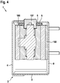
- the sectional view in 4 makes it clear that the rear wall 9 is located between the door leaf 104 (mounting surface) and the mounting plate 102.
- the Figures 5 to 7 show a variant of the first embodiment.
- the box 2 in particular the base body 3, is open at the rear with a recess 11.
- a peripheral area of the rear wall is formed around the recess 11 and can rest against the door leaf 104 in a sealing manner.
- Corresponding openings 10 for fastening means are also located in this area of the rear wall.
- the door operator 100 or its mounting plate 102 can be positioned in the recess 11 of the box 2 so that the door operator 100 or its mounting plate 102 directly contacts the door leaf 104 and the box 2 also seals directly against the door leaf 104 . This is advantageous, for example, when retrofitting a door operator 100 with box 2.
- an oil pan 8 can be positioned in the box 2.
- an oil binding agent is preferably arranged in the box 2.
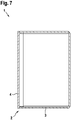
- Figure 7 shows a sectional view of an embodiment of the cover 4 as an alternative to the one in 4 shown construction.
- the cover 4 surrounds the base body 3, whereas according to 7 the cover 4 engages in the base body 3 .
- an airtight connection between the cover 4 and the base body 3 is provided, for example by gluing or sealing.
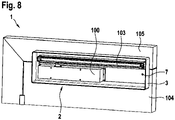
- the box 2 can be designed so large that it encapsulates not only the door operator 100 but also the linkage 103.
- the door operator 100 and the box 2 are attached to the door panel 104 .
- the box 2 extends upwards over the door leaf 104 into the area of the frame 105 and thus also accommodates the linkage 103 .
- the box 2 In the area of the linkage 103, ie above the door leaf 104, the box 2 is open at the back so that the door can be opened. When the door is closed, however, the box 2 rests against the frame 105 in a sealing manner.
Landscapes
- Special Wing (AREA)
Abstract
Die Erfindung betrifft einen Türbetätiger-Brandschutzanordnung (1), umfassend eine Box (2), ausgebildet zum luftdichten Kapseln eines Türbetätigers (100).
Description
- Vorliegende Erfindung betrifft eine Türbetätiger-Brandschutzanordnung, zur Verwendung mit einem Türbetätiger, insbesondere Türschließer oder Türantrieb.
- Türbetätiger werden dazu verwendet, Türen zu Schließen und/oder zu Öffnen. Als Türbetätiger werden insbesondere Türschließer und Türantriebe bezeichnet. Beim Türschließer wird im Regelfall durch die manuelle Öffnungsbewegung ein Federspeicher geladen. Die dabei gespeicherte Energie wird zum Schließen der Tür genutzt. Beim Türantrieb kann beispielsweise mittels Elektromechanik oder Hydraulik die Tür selbstständig geöffnet und/oder geschlossen werden. Türbetätiger werden üblicherweise auf dem Türblatt oder Zarge bzw. Wand befestigt.
- Insbesondere bei Brandschutztüren ist zu beachten, dass in den Türbetätigern oftmals brennbare Fluide, insbesondere Hydrauliköle, zur Anwendung kommen. Durch geeignete Maßnahmen ist möglichst zu vermeiden, dass der Türbetätiger sich im Brandfall entzündet.
- Es ist Aufgabe vorliegender Erfindung, eine Türbetätiger-Brandschutzanordnung anzugeben, die einen möglichst sicheren Betrieb eines Türbetätigers ermöglicht.
- Die Lösung der Aufgabe erfolgt durch die Merkmale des unabhängigen Anspruchs. Die abhängigen Ansprüche haben bevorzugte Ausgestaltungen der Erfindung zum Gegenstand.
- Die Türbetätiger-Brandschutzanordnung umfasst eine Box. Diese Box ist dazu ausgebildet, einen kompletten Türbetätiger luftdicht zu kapseln. Bei der Box handelt es sich somit nicht um einen Bestandteil des üblichen Türbetätigers, also des Türschließers oder des Türantriebs, und auch nicht um einen bestimmten Bereich innerhalb des Türbetätigers. Vielmehr ist die Box so groß ausgestaltet, dass der vollständige Türbetätiger innerhalb der Box Platz findet und durch die Box luftdicht gekapselt werden kann.
- Die Box ist insbesondere aus einem nicht-brennbaren Material, beispielsweise Metall, gefertigt. Die Box kann so ausgestaltet sein, dass sie für sich genommen den Türbetätiger luftdicht kapselt. Allerdings ist es auch möglich, dass die Box an ihrer Rückseite offen ist und zusammen mit ihrer Montagefläche, insbesondere dem Türblatt, einen abgeschlossenen luftdichten Raum zur Aufnahme des Türbetätigers bildet.
- In dem durch die Box gebildeten, nach außen hin luftdicht abgeschlossenen Raum, befindet sich entsprechend wenig Luft bzw. Sauerstoff, so dass es bei einer Erwärmung des Türbetätigers zu keiner Entzündung kommt oder falls sich ein Bestandteil des Türbetätigers entzündet, das Feuer möglichst schnell aufgrund von Sauerstoffmangel erlischt. Insbesondere kann solch ein Ereignis eintreten, wenn aufgrund eines Brandes sich der Türbetätiger erwärmt und Hydraulikfluid aus dem Türbetätiger austritt. Dieses Fluid könnte sich aufgrund der herrschenden Temperaturen entzünden, befindet sich jedoch erfindungsgemäß nach Austritt aus dem Türbetätiger noch innerhalb der Box und somit innerhalb des gekapselten Bereichs, in dem möglichst wenig Sauerstoff vorhanden ist.
- Türbetätiger weisen üblicherweise eine Abtriebsachse auf, die vom Türbetätiger angetrieben wird, beispielsweise durch eine Schließerfeder im Türschließer oder durch einen entsprechenden Antrieb im Türantrieb.
- Diese Abtriebsachse wird über ein Gestänge angebunden. Befindet sich der Türbetätiger am Türblatt, so erfolgt über das Gestänge die Verbindung zur Zarge bzw. Wand. Bei dem Gestänge kann es sich beispielsweise um ein Scherengestänge oder ein Gleitschienengestänge handeln.
- Die Box der Türbetätiger-Brandschutzanordnung weist vorzugsweise eine Achsöffnung auf. Im montierten Zustand kann die Abtriebsachse des Türbetätigers durch die Achsöffnung nach außen ragen oder die Abtriebsachse befindet sich innerhalb der Box fluchtend mit der Achsöffnung, so dass durch die Achsöffnung von außen hindurch das Gestänge in die Box ragen kann.
- An der Achsöffnung befindet sich vorzugsweise eine Dichtung. Die Dichtung sorgt für einen luftdichten Abschluss zwischen der Achsöffnung bzw. Box und der Abtriebsachse und/oder dem Gestänge. Dabei sieht eine bevorzugte Variante vor, dass die Dichtung aus intumeszierendem Material gefertigt ist und sich somit bei thermischer Einwirkung ausdehnt. So kann durchaus vorgesehen sein, dass die Dichtung im normalen Betrieb der Türbetätiger-Brandschutzanordnung bzw. des Türbetätigers nicht dichtend abschließt und erst bei entsprechender thermischer Einwirkung, also im Brandfall, sich ausdehnt und die Achsöffnung abdichtet.
- Vorzugsweise weist die Box ein Überdruckventil auf, das bei einem Überdruck im Inneren der Box zur Umgebung hin öffnet. Selbstverständlich ist dieses Überdruckventil so ausgebildet, dass es nur in Richtung von innen nach außen öffnet und somit keine Luft bzw. Sauerstoff in das Innere der Box lässt. Vorzugsweise ist das Ventil so angeordnet, dass im Einsatz- bzw. Überdruckfall, die entweichenden Gase in eine von der Tür wegweisenden Richtung entlässt, damit diese Gase sich nicht an der heißen Tür und/oder Zarge entzünden.
- Die Türbetätiger-Brandschutzanordnung weist vorzugsweise im Inneren der Box ein Ölbindemittel auf. Zusätzlich oder alternativ kann in der Box eine Ölwanne ausgebildet sein, in der sich austretendes Hydraulikfluid sammelt. Das Ölbindemittel befindet sich insbesondere in dieser Ölwanne. Die Ölwanne kann auch integraler Bestandteil der Box sein.
- An der Box ist eine Rückseite definiert. Mit dieser Rückseite liegt die Box vorzugsweise an ihrer Montagefläche, also insbesondere dem Türblatt, an. Gemäß einer bevorzugten Ausgestaltung ist die Box an ihrer Rückseite mit einer Rückwand geschlossen. Diese Rückwand kann trotz ihrer geschlossenen Ausgestaltung Öffnungen zum Durchführen von Befestigungsmitteln, insbesondere Schrauben, aufweisen. Zwischen der Rückwand und der Montagefläche wird insbesondere eine Dichtung und/oder Verklebung positioniert. Zusätzlich oder alternativ kann auch eine Abdichtung im Bereich der Öffnungen für die Befestigungsmittel vorgesehen sein.
- Des Weiteren ist bevorzugt vorgesehen, dass die Box einen Grundkörper und einen Deckel aufweist. Der Grundkörper erstreckt sich vorzugsweise geschlossen ringförmig rund um den Türbetätiger und ist auf seiner Vorderseite durch den Deckel verschlossen. Der Deckel und der Grundkörper sind zur luftdichten Verbindung ausgebildet. Insbesondere ist vorgesehen, den Deckel mit dem Grundkörper zu verkleben. Zusätzlich oder alternativ kann auch eine sonstige Dichtung zwischen Deckel und Grundkörper z.B. in Verbindung mit einer Verschraubung vorgesehen sein.
- Die Türbetätiger-Brandschutzanordnung umfasst neben der Box vorzugsweise auch den Türbetätiger, der zur vollständigen Anordnung innerhalb der Box ausgebildet ist. Dieser Türbetätiger weist vorzugsweise ein eigenes Gehäuse auf, in dem zumindest eine Hydraulikdruckkammer ausgebildet ist. Insbesondere handelt es sich bei dem Gehäuse um ein Metallgehäuse, beispielsweise aus Aluminium-Druckguss. In dem Gehäuse befinden sich insbesondere mehrere Hydraulikdruckkammern. Die zumindest eine Hydraulikdruckkammer wird dazu verwendet, um die Abtriebsachse des Türbetätigers zu bewegen. Bei Ausgestaltung des Türbetätigers als Türschließer befindet sich in dem Gehäuse vorzugsweise auch die Schließerfeder. Der Türbetätiger kann zusätzlich zu seinem Gehäuse auch eine Verkleidung aufweisen, die das Gehäuse umgibt. Dieser Türbetätiger mit seinem Gehäuse und optionaler Verkleidung befindet sich vollständig innerhalb der Box.
- Wie beschrieben, kann die Box eine geschlossene Rückwand aufweisen. In diesem Fall wird bei der Montage zunächst die Box positioniert und dann der Türbetätiger oder dessen Montageplatte aufgesetzt, so dass sich die Rückwand zwischen der Montagefläche (Türblatt) und dem Türbetätiger bzw. dessen Montageplatte befindet. Entsprechend liegt der Türbetätiger oder dessen Montageplatte innenseitig an der Rückwand an.
- Bei einer alternativen Ausgestaltung ist es möglich, dass die Box an ihrer Rückseite offen ist, so dass der Türbetätiger bzw. seine Montageplatte direkt an der Montagefläche anliegt. Die Rückseite der Box ist dann entsprechend ausgebildet, um den Türbetätiger bzw. seine Montageplatte geschlossen umlaufend zu umgeben und dabei dichtend an der Montagefläche anzuliegen.
- Des Weiteren ist bevorzugt vorgesehen, dass die Türbetätiger-Brandschutzanordnung auch das Gestänge umfasst. Das Gestänge ist beispielsweise als Scherengestänge oder Gleitschienengestänge ausgebildet.
- Wie bereits beschrieben, kann in der Box eine Achsöffnung vorgesehen sein, wobei dann das Gestänge außerhalb der Box angeordnet wird. Gemäß einer alternativen Variante ist die Box so groß gestaltet, dass sie nicht nur den Türbetätiger, sondern auch das vollständige Gestänge luftdicht kapselt; wobei vorgesehen ist, dass diese luftdichte Kapselung insbesondere nur im geschlossenen Zustand der Tür vorliegt.
- Für das Kapseln des Türbetätigers und des Gestänges ist insbesondere vorgesehen, dass die Box am Türblatt montiert ist und nach oben über das Türblatt hinweg ragt und dadurch das Gestänge mit aufnehmen kann. Die Box ragt somit in den Bereich der Zarge und ist im Bereich der Zarge rückseitig offen. Beim Öffnen der Türe löst sich die Box von der Zarge und ist nicht luftdicht. Bei geschlossener Lage der Türe liegt die Box allerdings im Bereich der Zarge luftdicht an der Zarge an und kann dadurch die luftdichte Kapselung des Türbetätigers samt Gestänge ermöglichen.
- Die Erfindung wird nun anhand mehrerer Ausführungsbeispiele näher beschrieben. Dabei zeigen:
- Fig. 1
- eine erfindungsgemäße Türbetätiger-Brandschutzanordnung gemäß einem ersten Ausführungsbeispiel,
- Fig. 2
- eine Box der erfindungsgemäßen Türbetätiger-Brandschutzanordnung gemäß dem ersten Ausführungsbeispiel im geöffneten Zustand,
- Fig. 3
- eine Rückseite der Box aus
Fig. 2 , - Fig. 4
- eine Schnittansicht der Box aus
Fig. 3 samt Türbetätiger, - Fig. 5 bis 7
- eine Variante der Box der erfindungsgemäßen Türbetätiger Brandschutzanordnung gemäß dem ersten Ausführungsbeispiel, und
- Fig. 8
- die erfindungsgemäße Türbetätiger-Brandschutzanordnung gemäß einem zweiten Ausführungsbeispiel.
- Im Folgenden wird eine Türbetätiger-Brandschutzanordnung 1 gemäß mehrerer Ausführungsbeispiele anhand der
Fig. 1 bis 8 im Detail beschrieben. Gleiche bzw. funktional gleiche Bauteile sind dabei stets mit den gleichen Bezugszeichen versehen. - Gemäß
Fig. 1 umfasst die Türbetätiger-Brandschutzanordnung 1 eine Box 2, die dazu verwendet wird, einen Türbetätiger 100 luftdicht zu kapseln. Insbesondere umfasst die Türbetätiger-Brandschutzanordnung 1 auch den Türbetätiger 100. Der Türbetätiger 100 kann als Türschließer oder Türantrieb ausgebildet sein. Der Türbetätiger 100 kann über eine Montageplatte 102 (s.Fig. 4 ) an seiner Montagefläche montiert sein. Des Weiteren weist der Türbetätiger 100 eine Abtriebsachse 101 auf. -
Fig. 1 zeigt ferner ein Gestänge 103, das, hier ausgebildet als Gleitschienengestänge, die Abtriebsachse 101 mit einer Zarge 105 einer Tür verbindet. In der Zarge 105 ist ein Türblatt 104 drehbar angeordnet. Der Türbetätiger 100 sowie die Box 2 sind am Türblatt 104 befestigt. -
Fig. 2 zeigt eine Vorderseite der Box 2 im geöffneten Zustand. Demgemäß umfasst die Box einen Grundkörper 3 und einen Deckel 4. Der Grundkörper 3 umgibt geschlossen umlaufend den Türbetätiger 100. Auf der Oberseite des Grundkörpers 3 ist eine Achsöffnung 5 vorgesehen. Über diese Achsöffnung 5 ist die Abtriebsachse 101 des Türbetätigers 100 zugänglich. - Die Box 2 weist ein Überdruckventil 7 auf, dass sich im gezeigten Ausführungsbeispiel im Deckel 4 befindet.
- Der Grundkörper 3 der Box 2 weist eine in
Fig. 3 dargestellte Rückwand 9 auf. Diese Rückwand 9 ist in dieser Konstruktion eine geschlossene Fläche und weist lediglich Öffnungen 10 für Befestigungsmittel auf. - Die Schnittdarstellung in
Fig. 4 verdeutlicht, dass sich die Rückwand 9 zwischen dem Türblatt 104 (Montagefläche) und der Montageplatte 102 befindet. - Des Weiteren zeigt die Schnittdarstellung in
Fig. 4 , dass an der Achsöffnung 5 eine Dichtung 6 angeordnet ist. Für die Dichtung 6 ist hier ein intumeszierendes Material verwendet, das bei thermischer Einwirkung sein Volumen vergrößert und dadurch die Achsöffnung 5 abdichtet. - Die
Fig. 5 bis 7 zeigen eine Variante des ersten Ausführungsbeispiels. GemäßFig. 5 und 6 ist die Box 2, insbesondere der Grundkörper 3, an der Rückseite mit einer Aussparung 11 offen. Rund um die Aussparung 11 ist ein umlaufender Bereich der Rückwand ausgebildet, der dichtend an dem Türblatt 104 anliegen kann. In diesem Bereich der Rückwand befinden sich auch entsprechende Öffnungen 10 für Befestigungsmittel. - In der Aussparung 11 der Box 2 kann der Türbetätiger 100 bzw. dessen Montageplatte 102 positioniert werden, so dass der Türbetätiger 100 bzw. dessen Montageplatte 102 unmittelbar das Türblatt 104 kontaktiert und die Box 2 ebenfalls direkt gegenüber dem Türblatt 104 abdichtet. Dieses ist beispielsweise vorteilhaft bei einer Nachrüstung eines Türbetätigers 100 mit der Box 2.
- Unabhängig von der Gestaltung der Rückseite der Box 2 kann, wie dies in den
Fig. 5 und 6 gezeigt ist, eine Ölwanne 8 in der Box 2 positioniert werden. In dieser Ölwanne 8 oder auch ohne der Ölwanne 8, wird vorzugsweise ein Ölbindemittel in der Box 2 angeordnet. -
Fig. 7 zeigt in einer Schnittdarstellung eine Ausgestaltung des Deckels 4 als Alternative zu der inFig. 4 gezeigten Konstruktion. GemäßFig. 4 umgreift der Deckel 4 den Grundkörper 3, wohingegen gemäßFig. 7 der Deckel 4 in den Grundkörper 3 eingreift. In beiden Varianten ist eine luftdichte Verbindung zwischen Deckel 4 und Grundkörper 3 vorgesehen, beispielsweise durch Verkleben oder Dichtung. -
Fig. 8 zeigt gemäß einem zweiten Ausführungsbeispiel, dass die Box 2 so groß ausgestaltet werden kann, dass sie nicht nur den Türbetätiger 100, sondern auch das Gestänge 103 kapselt. Der Türbetätiger 100 sowie die Box 2 sind an dem Türblatt 104 befestigt. Die Box 2 erstreckt sich nach oben über das Türblatt 104 hinweg bis in den Bereich der Zarge 105 und nimmt somit auch das Gestänge 103 auf. - Im Bereich des Gestänges 103, also über dem Türblatt 104, ist die Box 2 an ihrer Rückseite offen, so dass die Tür geöffnet werden kann. Im geschlossenen Zustand der Tür allerdings liegt die Box 2 dichtend an der Zarge 105 an.
-
- 1
- Türbetätiger-Brandschutzanordnung
- 2
- Box
- 3
- Grundkörper
- 4
- Deckel
- 5
- Achsöffnung
- 6
- Dichtung
- 7
- Überdruckventil
- 8
- Ölwanne
- 9
- Rückwand
- 10
- Öffnung
- 11
- Aussparung
- 100
- Türbetätiger
- 101
- Abtriebsachse
- 102
- Montageplatte
- 103
- Gestänge
- 104
- Türblatt
- 105
- Zarge
Claims (13)
- Türbetätiger-Brandschutzanordnung (1), umfassend• eine Box (2), ausgebildet zum luftdichten Kapseln eines Türbetätigers (100).
- Türbetätiger-Brandschutzanordnung nach Anspruch 1, wobei in der Box (2) eine Achsöffnung (5) zum Anschließen eines Gestänges (103) an eine Abtriebsachse (101) des Türbetätigers (100) ausgebildet ist.
- Türbetätiger-Brandschutzanordnung nach Anspruch 2, wobei die Box (2) rundum die Achsöffnung (5) eine Dichtung (6), vorzugsweise aus intumeszierendem Material, aufweist.
- Türbetätiger-Brandschutzanordnung nach einem der vorhergehenden Ansprüche, wobei an der Box (2) ein Überdruckventil (7) angeordnet ist.
- Türbetätiger-Brandschutzanordnung nach einem der vorhergehenden Ansprüche, wobei in der Box (2) ein Ölbindemittel angeordnet ist.
- Türbetätiger-Brandschutzanordnung nach einem der vorhergehenden Ansprüche, wobei die Box (2) eine Rückwand (9) aufweist, die, mit Ausnahme von optionalen Öffnungen (10) für Befestigungsmittel, geschlossen ist.
- Türbetätiger-Brandschutzanordnung nach einem der vorhergehenden Ansprüche, wobei die Box (2) einen Grundkörper (3) und einen Deckel (4) aufweist, wobei der Deckel (4) zur luftdichten Verbindung mit dem Grundkörper (3) ausgebildet ist.
- Türbetätiger-Brandschutzanordnung nach einem der vorhergehenden Ansprüche, umfassend den Türbetätiger (100), der zur vollständigen Anordnung in der Box (2) ausgebildet ist.
- Türbetätiger-Brandschutzanordnung nach Anspruch 8, wobei der Türbetätiger (100) ein Gehäuse aufweist, indem zumindest eine Hydraulikdruckkammer ausgebildet ist.
- Türbetätiger-Brandschutzanordnung nach einem der Ansprüche 8 oder 9, wobei die Box (2) die Rückwand (9) aufweist, an der der Türbetätiger (100) oder dessen Montageplatte (102) innenseitig anliegt.
- Türbetätiger-Brandschutzanordnung nach einem der vorhergehenden Ansprüche, umfassend ein am Türbetätiger angeschlossenes Gestänge (103), wobei die Box zur Aufnahme und luftdichten Kapselung des Türbetätigers (100) und des Gestänges (103) ausgebildet ist.
- Türbetätiger-Brandschutzanordnung nach einem der vorhergehenden Ansprüche, umfassend eine Tür, wobei der Türbetätiger (100) an einem Türblatt (104) der Tür befestigt ist.
- Türbetätiger-Brandschutzanordnung nach Anspruch 12, wobei sich die Box (2) zur Kapselung des Gestänges (103) über das Türblatt (104) hinweg erstreckt und im geschlossenen Zustand der Tür luftdicht an der Zarge (105) anliegt.
Priority Applications (1)
| Application Number | Priority Date | Filing Date | Title |
|---|---|---|---|
| EP21185318.9A EP4119756A1 (de) | 2021-07-13 | 2021-07-13 | Türbetätiger-brandschutzanordnung |
Applications Claiming Priority (1)
| Application Number | Priority Date | Filing Date | Title |
|---|---|---|---|
| EP21185318.9A EP4119756A1 (de) | 2021-07-13 | 2021-07-13 | Türbetätiger-brandschutzanordnung |
Publications (1)
| Publication Number | Publication Date |
|---|---|
| EP4119756A1 true EP4119756A1 (de) | 2023-01-18 |
Family
ID=76920573
Family Applications (1)
| Application Number | Title | Priority Date | Filing Date |
|---|---|---|---|
| EP21185318.9A Withdrawn EP4119756A1 (de) | 2021-07-13 | 2021-07-13 | Türbetätiger-brandschutzanordnung |
Country Status (1)
| Country | Link |
|---|---|
| EP (1) | EP4119756A1 (de) |
Citations (4)
| Publication number | Priority date | Publication date | Assignee | Title |
|---|---|---|---|---|
| CH437042A (de) * | 1966-03-10 | 1967-05-31 | Appatex Textil Apparate Ag | Türschliessvorrichtung mit einem Dämpfungskolben |
| JP2006348652A (ja) * | 2005-06-17 | 2006-12-28 | Ykk Ap株式会社 | 建具 |
| JP2009180036A (ja) * | 2008-01-31 | 2009-08-13 | Ryobi Ltd | ドアクローザ |
| KR20110039084A (ko) * | 2009-10-09 | 2011-04-15 | (주) 아이레보 금강씨에스 | 방화용 도어 클로저 |
-
2021
- 2021-07-13 EP EP21185318.9A patent/EP4119756A1/de not_active Withdrawn
Patent Citations (4)
| Publication number | Priority date | Publication date | Assignee | Title |
|---|---|---|---|---|
| CH437042A (de) * | 1966-03-10 | 1967-05-31 | Appatex Textil Apparate Ag | Türschliessvorrichtung mit einem Dämpfungskolben |
| JP2006348652A (ja) * | 2005-06-17 | 2006-12-28 | Ykk Ap株式会社 | 建具 |
| JP2009180036A (ja) * | 2008-01-31 | 2009-08-13 | Ryobi Ltd | ドアクローザ |
| KR20110039084A (ko) * | 2009-10-09 | 2011-04-15 | (주) 아이레보 금강씨에스 | 방화용 도어 클로저 |
Similar Documents
| Publication | Publication Date | Title |
|---|---|---|
| DE3138753C2 (de) | Feuersicherer Ventilantrieb | |
| DE1775691A1 (de) | Ventildichtung | |
| EP3916183B1 (de) | Türbetätiger zum öffnen und/oder schliessen einer tür | |
| DE102021132643B3 (de) | Druckbehälter und Verfahren zu dessen Befüllen | |
| DE2811879C2 (de) | Eigenmediumgesteuertes Schaltventil | |
| EP4182531A1 (de) | Brandschutzbefestigungseinrichtung zur befestigung eines türbetätigers | |
| EP3644402A1 (de) | Ventil zum druckausgleich und/oder drucküberlastabbau für ein batteriegehäuse | |
| DE3328857C2 (de) | ||
| EP2019915A1 (de) | Thermostatventil | |
| DE202017102260U1 (de) | Frostsicheres Ventil | |
| DE10120319A1 (de) | Vorgesteuertes Ventil mit einem Druckausgleichskanal | |
| DE102006037831A1 (de) | Pyrotechnischer Aktor | |
| EP3173561B1 (de) | Gehäuse für einen antrieb einer tür oder eines fensters | |
| DE202007010395U1 (de) | Hubventil | |
| DE3900817A1 (de) | Gasfeder | |
| DE202021106738U1 (de) | Druckbehälter | |
| DE102010029024A1 (de) | Antrieb für einen Flügel einer Tür oder eines Fensters | |
| DE102007025781A1 (de) | Thermostatventil | |
| EP2388422B1 (de) | Antrieb für einen Flügel einer Tür oder eines Fensters | |
| DE3008995A1 (de) | Vorrichtung zum oeffnen und schliessen einer rauch- und waermeabzugsklappe | |
| DE4021875A1 (de) | Gasdichter flachschieber fuer hohe temperaturen | |
| DE1951465B2 (de) | Hydraulische sicherheitsvorrichtung fuer kessel-bodenventile | |
| EP0892175A1 (de) | Druckmittelbetätigbarer Arbeitszylinder | |
| CH647059A5 (en) | Safety shut-off valve, especially for gas-pressure regulating systems | |
| DE102022207560A1 (de) | Türantrieb |
Legal Events
| Date | Code | Title | Description |
|---|---|---|---|
| PUAI | Public reference made under article 153(3) epc to a published international application that has entered the european phase |
Free format text: ORIGINAL CODE: 0009012 |
|
| STAA | Information on the status of an ep patent application or granted ep patent |
Free format text: STATUS: THE APPLICATION HAS BEEN PUBLISHED |
|
| AK | Designated contracting states |
Kind code of ref document: A1 Designated state(s): AL AT BE BG CH CY CZ DE DK EE ES FI FR GB GR HR HU IE IS IT LI LT LU LV MC MK MT NL NO PL PT RO RS SE SI SK SM TR |
|
| STAA | Information on the status of an ep patent application or granted ep patent |
Free format text: STATUS: THE APPLICATION IS DEEMED TO BE WITHDRAWN |
|
| 18D | Application deemed to be withdrawn |
Effective date: 20230719 |