EP4119744B1 - Armstütze und arbeitsvorrichtung - Google Patents
Armstütze und arbeitsvorrichtung Download PDFInfo
- Publication number
- EP4119744B1 EP4119744B1 EP20924785.7A EP20924785A EP4119744B1 EP 4119744 B1 EP4119744 B1 EP 4119744B1 EP 20924785 A EP20924785 A EP 20924785A EP 4119744 B1 EP4119744 B1 EP 4119744B1
- Authority
- EP
- European Patent Office
- Prior art keywords
- plate
- side plate
- bending portion
- arm support
- connecting portion
- Prior art date
- Legal status (The legal status is an assumption and is not a legal conclusion. Google has not performed a legal analysis and makes no representation as to the accuracy of the status listed.)
- Active
Links
Images



Classifications
-
- E—FIXED CONSTRUCTIONS
- E04—BUILDING
- E04G—SCAFFOLDING; FORMS; SHUTTERING; BUILDING IMPLEMENTS OR AIDS, OR THEIR USE; HANDLING BUILDING MATERIALS ON THE SITE; REPAIRING, BREAKING-UP OR OTHER WORK ON EXISTING BUILDINGS
- E04G21/00—Preparing, conveying, or working-up building materials or building elements in situ; Other devices or measures for constructional work
- E04G21/02—Conveying or working-up concrete or similar masses able to be heaped or cast
-
- E—FIXED CONSTRUCTIONS
- E04—BUILDING
- E04G—SCAFFOLDING; FORMS; SHUTTERING; BUILDING IMPLEMENTS OR AIDS, OR THEIR USE; HANDLING BUILDING MATERIALS ON THE SITE; REPAIRING, BREAKING-UP OR OTHER WORK ON EXISTING BUILDINGS
- E04G21/00—Preparing, conveying, or working-up building materials or building elements in situ; Other devices or measures for constructional work
- E04G21/02—Conveying or working-up concrete or similar masses able to be heaped or cast
- E04G21/04—Devices for both conveying and distributing
- E04G21/0418—Devices for both conveying and distributing with distribution hose
- E04G21/0445—Devices for both conveying and distributing with distribution hose with booms
-
- A—HUMAN NECESSITIES
- A62—LIFE-SAVING; FIRE-FIGHTING
- A62C—FIRE-FIGHTING
- A62C27/00—Fire-fighting land vehicles
-
- B—PERFORMING OPERATIONS; TRANSPORTING
- B66—HOISTING; LIFTING; HAULING
- B66C—CRANES; LOAD-ENGAGING ELEMENTS OR DEVICES FOR CRANES, CAPSTANS, WINCHES, OR TACKLES
- B66C23/00—Cranes comprising essentially a beam, boom, or triangular structure acting as a cantilever and mounted for translatory of swinging movements in vertical or horizontal planes or a combination of such movements, e.g. jib-cranes, derricks, tower cranes
- B66C23/62—Constructional features or details
- B66C23/64—Jibs
- B66C23/68—Jibs foldable or otherwise adjustable in configuration
-
- B—PERFORMING OPERATIONS; TRANSPORTING
- B66—HOISTING; LIFTING; HAULING
- B66C—CRANES; LOAD-ENGAGING ELEMENTS OR DEVICES FOR CRANES, CAPSTANS, WINCHES, OR TACKLES
- B66C23/00—Cranes comprising essentially a beam, boom, or triangular structure acting as a cantilever and mounted for translatory of swinging movements in vertical or horizontal planes or a combination of such movements, e.g. jib-cranes, derricks, tower cranes
- B66C23/62—Constructional features or details
- B66C23/64—Jibs
- B66C23/70—Jibs constructed of sections adapted to be assembled to form jibs or various lengths
- B66C23/701—Jibs constructed of sections adapted to be assembled to form jibs or various lengths telescopic
- B66C23/705—Jibs constructed of sections adapted to be assembled to form jibs or various lengths telescopic telescoped by hydraulic jacks
-
- E—FIXED CONSTRUCTIONS
- E04—BUILDING
- E04G—SCAFFOLDING; FORMS; SHUTTERING; BUILDING IMPLEMENTS OR AIDS, OR THEIR USE; HANDLING BUILDING MATERIALS ON THE SITE; REPAIRING, BREAKING-UP OR OTHER WORK ON EXISTING BUILDINGS
- E04G21/00—Preparing, conveying, or working-up building materials or building elements in situ; Other devices or measures for constructional work
- E04G21/02—Conveying or working-up concrete or similar masses able to be heaped or cast
- E04G21/04—Devices for both conveying and distributing
-
- Y—GENERAL TAGGING OF NEW TECHNOLOGICAL DEVELOPMENTS; GENERAL TAGGING OF CROSS-SECTIONAL TECHNOLOGIES SPANNING OVER SEVERAL SECTIONS OF THE IPC; TECHNICAL SUBJECTS COVERED BY FORMER USPC CROSS-REFERENCE ART COLLECTIONS [XRACs] AND DIGESTS
- Y10—TECHNICAL SUBJECTS COVERED BY FORMER USPC
- Y10T—TECHNICAL SUBJECTS COVERED BY FORMER US CLASSIFICATION
- Y10T137/00—Fluid handling
- Y10T137/8593—Systems
- Y10T137/8807—Articulated or swinging flow conduit
Definitions
- the present invention relates to the technical field of working devices, in particular, to an arm support and a working device.
- JP S59 50987 U discloses an arm support as summarized in the preamble of claim 1. Further reference is made to CN 207 554 069 U , CN 106 499 187 A , WO 2016/059061 A1 , and CN 206 917 279 U .
- the present invention aims to solve at least one of the technical problems in the prior art or related art.
- a first aspect of the present invention provides an arm support with the features of claim 1.
- a second aspect of the present invention provides a working device with the features of claim 9.
- the first aspect of the present invention provides an arm support comprising a frame structure, wherein the arm support comprises: a top plate; a bottom plate, wherein the bottom plate and the top plate are oppositely disposed at an interval; a first side plate; a second side plate, wherein the second side plate and the first side plate are oppositely disposed at an interval; wherein a first side of the first side plate is provided with a first bending portion, at least a portion of the first bending portion and the top plate are attached and spliced to each other, a second side of the first side plate opposite to the first bending portion is provided with a second bending portion, at least a portion of the second bending portion and the bottom plate are attached and spliced to each other; and a first side of the second side plate is provided with a third bending portion, at least a portion of the third bending portion and the top plate are attached and spliced to each other, a second side of the second side plate opposite to the third bending portion is
- All the top plate, the bottom plate, the first side plate and the second side plate are of a plate structure with a uniform thickness, and the top plate and the bottom plate with an equal thickness can fully exert the compressive and tensile properties of the bottom plate and the top plate.
- corresponding mounting holes are machined in the first side plate and the second side plate according to the structural features of the arm support for installing an axle sleeve, an oil cylinder and etc., and the shape of the bottom plate is matched with a side of the first side plate and a side of the second side plate which are away from the top plate.
- the top plate is a flat plate
- the first bending portion and the third bending portion respectively form an included angle with the body of the first side plate and the body of the second side plate, and the included angle is 90°, and therefore, both the first bending portion and the third bending portion can be attached to the top plate.
- the second bending portion and the fourth bending portion can match the shape of the plate surface of the bottom plate. Therefore, the top plate, the bottom plate, the first side plate and the second side plate are spliced to each other, and then the arm support is assembled.
- the splicing structure is firm and simple and is suitable for the combined use of different materials, and this can be easily achieved. Therefore, compared with the arm support with an integral structure, the cost of the mold for making the arm support is reduced, and at the same time, the production efficiency of the arm support is improved.
- the above arm support can further comprise the following additional technical features.
- the first bending portion and the second bending portion are respectively integrally formed with the first side plate; and the third bending portion and the fourth bending portion are respectively integrally formed with the second side plate.
- the two ends of the first side plate are respectively bent to form the first bending portion and the second bending portion, thereby improving the molding efficiency of the first side plate.
- the two ends of the second side plate are respectively bent to form the third bending portion and the fourth bending portion, thereby improving the molding efficiency of the second side plate. Therefore, the production efficiency of the arm support is further improved.
- the arm support further comprises a first rib plate, provided on the first side plate and disposed between the first bending portion and the second bending portion; and a second rib plate, provided on the second side plate and disposed between the third bending portion and the fourth bending portion.
- the first rib plate and the first side plate are integrally formed, the second rib plate and the second side plate are further integrally formed, and this can not only increase the structure strength of the first side plate and the second side plate, but further simplify the structure and simplify the processing technology.
- the arm support further comprises: a middle body; a first connecting portion, provided at one end of the middle body in a length direction; a second connecting portion, provided at the other end of the middle body in a length direction; wherein, the first connecting portion, the second connecting portion and the middle body are enclosed and defined by the top plate, the bottom plate, the first side plate and the second side plate.
- the arm support is relatively long, wherein the first connecting portion, the second connecting portion and the middle body are enclosed and defined by the top plate, the bottom plate, the first side plate and the second side plate to form a frame structure.
- An oil cylinder mounting seat is provided in one end of the first side plate and one end of the second side plate of the middle body away from the top plate.
- the oil cylinder mounting seat comprises two oil cylinder mounting holes provided in the first side plate and the second side plate, and the two oil cylinder mounting holes are disposed opposite to each other.
- the third plate body extends an ear plate structure at the connection of the first connecting portion and the end portion of the top plate in a direction away from the second connecting portion and in a direction away from the top plate, and therefore, the side of the third plate body located at the first connecting portion away from the top plate is arc-shaped, and the bottom plate located at the first connecting portion is further arc-shaped, and then, the second bending portion located at the first connecting portion is further arc-shaped.
- the second connecting portion further has an ear plate structure, the side of the third plate body located at the second connecting portion away from the top plate is arc-shaped, and the bottom plate located at the second connecting portion is further arc-shaped, and then, the second bending portion located at the second connecting portion is further arc-shaped.
- the bottom plate located between the first connecting portion and the second connecting portion can be a plate structure, and thus, the second bending portion located between the first connecting portion and the second connecting portion is further a plate structure, so that the second bending portion is attached to the bottom plate; through the first bending portion and the second bending portion, the first side plate is spliced to the top plate and the bottom plate, and this simplifies the splicing structure and can be achieved easily, and can improve the splicing efficiency of the arm support.
- the fourth plate body extends an ear plate structure at the connection of the first connecting portion and the end portion of the top plate in a direction away from the second connecting portion and in a direction away from the top plate, and therefore, the side of the fourth plate body located at the first connecting portion away from the top plate is arc-shaped, and the bottom plate located at the first connecting portion is further arc-shaped, and then, the fourth bending portion located at the first connecting portion is further arc-shaped.
- the second connecting portion further has an ear plate structure, the side of the fourth plate body located at the second connecting portion away from the top plate is arc-shaped, and the bottom plate located at the second connecting portion is further arc-shaped, and then, the fourth bending portion located at the second connecting portion is further arc-shaped.
- the bottom plate located between the first connecting portion and the second connecting portion can be a plate structure, and thus, the fourth bending portion located between the first connecting portion and the second connecting portion is further a plate structure, so that the fourth bending portion is attached to the bottom plate; through the third bending portion and the fourth bending portion, the second side plate is spliced to the top plate and the bottom plate, and this simplifies the splicing structure and can be easily achieved, and can improve the splicing efficiency of the arm support.
- the aluminum alloy is lighter compared with a steel plate, and therefore, for the arm support assembled by joining a carbon fiber plate and an aluminum alloy plate, its weight is reduced and its compressive performance is further ensured, and compared with the arm support made from a pure carbon fiber material, the cost of raw materials is reduced.
- the cost of the mold for the manufactured arm support is further greatly reduced, and at the same time, compared with the integrally formed carbon fiber arm support, the molding efficiency of the arm support is further improved.
- a first steel guard plate is provided on the top of the first connecting portion, and the two opposite sides of the first steel guard plate are respectively connected with the first side plate and the second side plate;
- a second steel guard plate is provided at the bottom of the first connecting portion, and the second steel guard plate is attached to and fixed with the bottom plate;
- a third steel guard plate is provided on the top of the second connecting portion, and the two opposite sides of the third steel guard plate are respectively connected with the first side plate and the second side plate;
- a fourth steel guard plate is provided at the bottom of the second connecting portion, and the fourth steel guard plate is attached to and fixed with the bottom plate.
- the first steel guard plate is provided on the top of the inclined portion of the first connecting portion
- the second steel guard plate is provided at the bottom of the inclined portion of the first connecting portion
- the second steel guard plate and the bottom plate have the same radian, so that the second steel guard plate and the bottom plate are attached to each other at the portion of the first connecting portion.
- the third steel guard plate is provided on the top of the inclined portion of the second connecting portion
- the fourth steel guard plate is provided at the bottom of the inclined portion of the second connecting portion
- the fourth steel guard plate and the bottom plate have the same radian, so that the fourth steel guard plate and the bottom plate are attached to each other at the portion of the second connecting portion.
- the first side plate and/or the second side plate further comprises: a first plate body; a second plate body, disposed with the first plate body side by side; wherein a thickness of the first plate body is greater than a thickness of the second plate body, the first side plate and the second side plate are respectively provided with a first plate body at two ends in the length direction, and the second plate body is respectively connected with the two first plate bodies on two opposite sides by friction welding, to splice out the first side plate or the second side plate.
- the thickness of the first plate body is greater than that of the second plate body, so as to increase structure strength and play a better connecting function.
- the inner surface of the first plate body and the inner surface of the second plate body are in the same plane, that is, the outer surface of the first plate body protrudes from the outer surface of the second plate body, which can facilitate the installation of the axle sleeve and the like on the first connecting portion and the second connecting portion, and makes the connection between a plurality of arm supports more convenient.
- Friction welding is a method of using the heat generated by the mutual movement and the mutual friction of the end faces of a workpiece to achieve a thermoplastic state of end portions, and then quickly conducting upsetting and completing welding.
- Friction stir welding is a kind of friction welding.
- the friction stir welding further uses friction heat and plastic deformation heat as welding heat sources.
- the welding process of the friction stir welding is that a stirring needle of a cylinder shape or another shape (for example, a threaded cylinder) is extended into the joint of a workpiece, and the high-speed rotation of a welding head makes it rub against a welding workpiece material, and then the temperature of the material at the connection portion raises, and then the material is softened.
- the first plate body and the second plate body are connected to each other through the friction stir welding, which can ensure the integral structure strength of the first side plate or the second side plate.
- the arm support further comprises: an axle sleeve, connected with the first side plate and/or the second side plate through friction welding; wherein the first side plate and the second side plate are provided with at least two axle sleeves opposite to each other.
- the axle sleeve in the first side plate and the axle sleeve in the second side plate are symmetrically arranged, and the axle sleeve and the first side plate or the second side plate are further connected by friction welding, wherein the friction welding can further be friction stir welding.
- the friction stir welding is a mature welding process and is not repeated herein.
- the top plate and the bottom plate are respectively bonded with and mechanically connected with the first side plate and the second side plate.
- the first side plate is bonded with and mechanically connected with the top plate and the bottom plate
- the second side plate is bonded with and mechanically connected with the top plate and the bottom plate
- the mechanical connection is a fastener connecting or riveting
- the fastener connecting can be screw connection, bolt connection, and etc.
- the top plate and the bottom plate are respectively bonded with the first bending portion and the second bending portion, and then they are connected through fasteners.
- the top plate and the bottom plate are respectively bonded with the third bending portion and the fourth bending portion, and then they are connected through fasteners.
- the second aspect of the present invention provides a working device which comprises: a chassis; an arm support system, provided on the chassis, wherein the arm support system is provided with a pump tube for conveying materials; wherein the arm support system comprises a plurality of arm supports according to any one of the above embodiments, two adjacent arm supports are hinged to each other, and an arm support at the end portion is connected with the chassis.
- the working device provided in the present invention comprises the arm support in any one of the designs in the first aspect, and thus it has all the beneficial effects of the arm support of any one of the designs in the first aspect, and is not repeated herein.
- the production method of the arm support of a carbon fiber composite material comprises inflating a retractable air bag to form an air bag with a first state, laying a carbon fiber prepreg on the outer surface of the air bag, obtaining a component and putting it into a box-shaped mold, and inflating the air bag, and then compressing and shaping the carbon fiber prepreg to obtain a second transition component.
- the second transition component is subjected to temperature rise and then solidified, and then cooled and demolded after solidification to obtain a carbon fiber arm support.
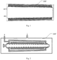
- the cost of the integral carbon fiber arm support 100' is relatively high, and this leads to relatively high manufacturing costs of the arm support and a lowered performance-price ratio; and the mold used for the integrally formed arm support model is complex and expensive, and the investment in early process verification is too large. Each structural optimization requires re-adjusting the mold, and this is further extremely unfavorable for the costs of later mass production.
- a carbon fiber arm support 100" for a concrete pump truck is provided with an outer mold, the outer mold is composed of an upper mold and a lower mold and has a hollow structure, and the carbon fiber prepreg for manufacturing the carbon fiber arm support 100" is laid on the inner surfaces of the upper mold and the lower mold.
- the mechanical properties and dimensions of this composite material arm support have extremely high requirements for mold tooling and processes, and this will lead to process instability, and then leads to problems such as internal defects, and there is a connection strength problem in steel structure components, aluminum structure components and carbon fiber composite material structure components.
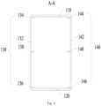
- the present embodiment provides an arm support 100 with a frame structure, wherein the arm support 100 comprises: a top plate 110, a bottom plate 120, a first side plate 130 and a second side plate 140, wherein the bottom plate 120 and the top plate 110 are oppositely disposed at an interval, and the second side plate 140 and the first side plate 130 are oppositely disposed at an interval; wherein a first side of the first side plate 130 is provided with a first bending portion 134, at least a portion of the first bending portion 134 is attached and spliced to the top plate 110, a second side of the first side plate 130 opposite to the first bending portion 134 is provided with a second bending portion 136, at least a portion of the second bending portion 136 is attached and spliced to the bottom plate 120; and a first side of the second side plate 140 is provided with a third bending portion 144, at least a portion of the third bending portion 144 is attached and spliced to
- all the top plate 110, the bottom plate 120, the first side plate 130 and the second side plate 140 are of a plate structure with a uniform thickness, the top plate 110 and the bottom plate 120 with an equal thickness can fully exert the compressive and tensile properties of the bottom plate 120 and the top plate 110.
- corresponding mounting holes are machined in the first side plate 130 and the second side plate 140 according to the structural features of the arm support 100 for installing an axle sleeve 150, an oil cylinder and etc., and the shape of the bottom plate 120 is matched with a side of the first side plate 130 and a side of the second side plate 140 away from the top plate 110.
- the top plate is a flat plate
- the first bending portion and the third bending portion respectively form an included angle with the body of the first side plate 130 and the body of the second side plate 140, and the included angle is 90°, and therefore, both the first bending portion and the third bending portion can be attached to the top plate.
- the second bending portion and the fourth bending portion can match the shape of the plate surface of the bottom plate.
- the top plate 110, the bottom plate 120, the first side plate 130 and the second side plate 140 are spliced to each other, and then the arm support 100 is assembled, and compared with the arm support 100 with an integral structure, the cost of the mold for making the arm support 100 is reduced, and at the same time, the production efficiency of the arm support 100 is improved.
- the present embodiment provides an arm support 100. Besides the technical features of the above embodiment, the present embodiment further comprises the following technical features.
- the first bending portion 134 and the second bending portion 136 are respectively integrally formed with the first side plate 130; and the third bending portion 144 and the fourth bending portion 146 are respectively integrally formed with the second side plate 140.
- the two ends of the first side plate 130 are respectively bent to form the first bending portion 134 and the second bending portion 136, thereby improving the molding efficiency of the first side plate.
- the two ends of the second side plate 140 are respectively bent to form the third bending portion 144 and the fourth bending portion 146, thereby improving the molding efficiency of the second side plate 140. Therefore, the production efficiency of the arm support 100 is further improved.
- the present embodiment provides an arm support 100. Besides the technical features of the above embodiments, the present embodiment further comprises the following technical features.
- the arm support 100 further comprises a first rib plate 138, provided on the first side plate 130 and disposed between the first bending portion 134 and the second bending portion 136; and a second rib plate 148, provided on the second side plate 140 and disposed between the third bending portion 144 and the fourth bending portion 146.
- first rib plate 138 and the first side plate 130 are integrally formed
- second rib plate 148 and the second side plate 140 are further integrally formed, and this can not only increase the structure strength of the first side plate 130 and the second side plate 140, but further simplify the structure and simplify the processing technology.
- the present embodiment provides an arm support 100. Besides the technical features of the above embodiments, the present embodiment further comprises the following technical features.
- the arm support 100 further comprises: a middle body 102, a first connecting portion 104 and a second connecting portion 106, wherein the first connecting portion 104 is provided at one end of the middle body 102 in a length direction; the second connecting portion 106 is provided at the other end of the middle body 102 in a length direction; wherein the first connecting portion 104, the second connecting portion 106 and the middle body 102 are enclosed and defined by the top plate 110, the bottom plate 120, the first side plate 130 and the second side plate 140, and the cross sections of the middle body 102 are equal to each other.
- the arm support 100 is relatively long, wherein the first connecting portion 104, the second connecting portion 106 and the middle body 102 are enclosed and defined by the top plate 110, the bottom plate 120, the first side plate 130 and the second side plate 140 to form a frame structure.
- An oil cylinder mounting seat 180 is provided at one end of the first side plate 130 and one end of the second side plate 140 of the middle body 102 away from the top plate 110.
- the oil cylinder mounting seat 180 comprises two oil cylinder mounting holes provided in the first side plate 130 and the second side plate 140, and the two oil cylinder mounting holes are disposed opposite to each other.
- the cross sections of the middle body 102 are equal to each other, and the middle body 102 has a simple structure and can be conveniently manufactured, and thus the manufacturing process can be simplified.
- the present embodiment provides an arm support 100. Besides the technical features of the above embodiments, the present embodiment further comprises the following technical features.
- the top plate 110 and the bottom plate 120 are respectively carbon fiber plates, and the first side plate 130 and the second side plate 140 are respectively aluminum alloy plates.
- a 7-series aluminum alloy is selected as the top plate 110 and the bottom plate 120, wherein, the 7-series aluminum alloy is a common alloy in aluminum alloys, and includes zinc and magnesium.
- the aluminum alloy is lighter compared with a steel plate. Therefore, for the arm support 100 assembled by joining carbon fiber plates and aluminum alloy plates, its weight is reduced and its compressive performance is further ensured, and compared with the arm support 100 made from a pure carbon fiber material, the cost of raw materials is reduced.
- the welding of aluminum alloys has not been the concern of the engineering field all the time, especially the 7 series aluminum alloy.
- the present invention boldly adopts a friction stir welding process of the 7 series aluminum alloy.
- the cost of the mold for the manufactured arm support 100 is further greatly reduced, and at the same time, compared with the integrally formed carbon fiber arm support, the molding efficiency of the arm support 100 is further improved.
- the present embodiment provides an arm support 100. Besides the technical features of the above embodiments, the present embodiment further comprises the following technical features.
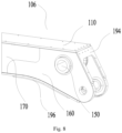
- the arm support 100 further comprises: a first steel guard plate 190, a second steel guard plate 192, a third steel guard plate 194 and a fourth steel guard plate 196, wherein the first steel guard plate is provided on the top of the first connecting portion 104, and the two opposite sides of the first steel guard plate 190 are respectively connected with the first side plate 130 and the second side plate 140; the second steel guard plate 192 is provided at the bottom of the first connecting portion 104, and the second steel guard plate 192 is attached to and fixed with the bottom plate 120; the third steel guard plate 194 is provided on the top of the second connecting portion 106, and the two opposite sides of the third steel guard plate 194 are respectively connected with the first side plate 130 and the second side plate 140; and the fourth steel guard plate 196 is provided at the bottom of the second connecting portion 106, and the fourth steel guard plate 196 is attached to and fixed with the bottom plate 120.
- the first connecting portion 104 and the second connecting portion 106 need to bear the extruding force and gravity generated by rotating connection in the case of hinged connection
- the first steel guard plate 190 is provided on the top of the inclined portion of the first connecting portion 104
- the second steel guard plate 192 is provided at the bottom of the inclined portion of the first connecting portion 104
- the second steel guard plate 192 and the bottom plate 120 have the same radian, so that the second steel guard plate 192 and the bottom plate 120 are attached to each other at the portion of the first connecting portion 104.
- the third steel guard plate 194 is provided on the top of the inclined portion of the second connecting portion 106
- the fourth steel guard plate 196 is provided at the bottom of the inclined portion of the second connecting portion 106
- the fourth steel guard plate 196 and the bottom plate 120 have the same radian, so that the fourth steel guard plate 196 and the bottom plate 120 are attached to each other at the portion of the second connecting portion 106.
- the first steel guard plate 190 and the third steel guard plate 194 are welded with the first side plate 130 and the second side plate 140 respectively and connected by fasteners. Other connection structures can further be used.
- the second steel guard plate 192 and the fourth steel guard plate 196 are respectively connected with the bottom plate 120, for example, friction welding can be used, and then connection is implemented by fasteners such as screws.
- the present embodiment provides an arm support 100. Besides the technical features of the above embodiments, the present embodiment further comprises the following technical features.
- the first side plate 130 comprises: a third plate body 132, a first bending portion 134 and a second bending portion 136, wherein the first bending portion 134 is provided at one side of the third plate body 132; the second bending portion 136 is provided at the other side of the third plate body 132 opposite to the first bending portion 134; wherein the first bending portion 134 and the second bending portion 136 are respectively integrally formed with the third plate body 132, at least a portion of the first bending portion 134 is attached to the top plate 110, and at least a portion of the second bending portion 136 is attached to the bottom plate 120.
- the first bending portion 134 and the second bending portion 136 are respectively integrally formed with the third plate body 132; the first bending portion 134 and the second bending portion 136 respectively form an included angle with the third plate body 132, and the included angle is 90°, the top plate 110 is a plate structure, and therefore, the first bending portion 134 can be attached to the top plate 110.
- the third plate body 132 extends an ear plate structure at the connection of the first connecting portion 104 and the end portion of the top plate 110 in a direction away from the second connecting portion 106 and in a direction away from the top plate 110, and therefore, the side of the third plate body 132 located at the first connecting portion 104 away from the top plate 110 is arc-shaped, and the bottom plate 120 located at the first connecting portion 104 is further arc-shaped, and then, the second bending portion 136 located at the first connecting portion 104 is further arc-shaped.
- the second connecting portion 106 further has an ear plate structure, the side of the third plate body 132 located at the second connecting portion 106 away from the top plate 110 is arc-shaped, and the bottom plate 120 located at the second connecting portion 106 is further arc-shaped, and then, the second bending portion 136 located at the second connecting portion 106 is further arc-shaped.
- the bottom plate 120 located between the first connecting portion 104 and the second connecting portion 106 can be a plate structure, and thus, the second bending portion 136 located between the first connecting portion 104 and the second connecting portion 106 is further a plate structure, so that the second bending portion 136 is attached to the bottom plate 120; through the first bending portion 134 and the second bending portion 136, the first side plate 130 is spliced to the top plate 110 and the bottom plate 120, and this simplifies the splicing structure and can be achieved easily, and can improve the splicing efficiency of the arm support 100.
- the second side plate 140 comprises: a fourth plate body 142, a third bending portion 144 and a fourth bending portion 146, wherein the third bending portion 144 is provided at one end of the fourth plate body 142, and the fourth bending portion 146 is provided at the other end of the fourth plate body 142 opposite to the third bending portion 144; wherein the third bending portion 144 and the fourth bending portion 146 are respectively integrally formed with the fourth plate body 142, at least a portion of the third bending portion 144 is attached to the top plate 110, and at least a portion of the fourth bending portion 146 is attached to the bottom plate 120.
- the third bending portion 144 and the fourth bending portion 146 are respectively integrally formed with the fourth plate body 142; the third bending portion 144 and the fourth bending portion 146 respectively form an included angle with the fourth plate body 142, and the included angle is 90°, the top plate 110 is a plate structure, and therefore, the third bending portion 144 can be attached to the top plate 110.
- the fourth plate body 142 extends an ear plate structure at the connection of the first connecting portion 104 and the end portion of the top plate 110 in a direction away from the second connecting portion 106 and in a direction away from the top plate 110, and therefore, the side of the fourth plate body 142 located at the first connecting portion 104 away from the top plate 110 is arc-shaped, and the bottom plate 120 located at the first connecting portion 104 is arc-shaped, and then, the fourth bending portion 146 located at the first connecting portion 104 is further arc-shaped.
- the second connecting portion 106 further has an ear plate structure, the side of the fourth plate body 142 located at the second connecting portion 106 away from the top plate 110 is arc-shaped, and the bottom plate 120 located at the second connecting portion 106 is further arc-shaped, and then, the fourth bending portion 146 located at the second connecting portion 106 is further arc-shaped.
- the bottom plate 120 located between the first connecting portion 104 and the second connecting portion 106 can be a plate structure, and thus, the fourth bending portion 146 located between the first connecting portion 104 and the second connecting portion 106 is further a plate structure, so that the fourth bending portion 146 is attached to the bottom plate 120; through the third bending portion 144 and the fourth bending portion 146, the second side plate 140 is spliced to the top plate 110 and the bottom plate 120, and this simplifies the splicing structure and can be easily achieved, and can improve the splicing efficiency of the arm support 100.
- the present embodiment provides an arm support 100. Besides the technical features of the above embodiments, the present embodiment further comprises the following technical features.
- the first side plate 130 and/or the second side plate 140 further comprises: a first plate body 160 and a second plate body 170, wherein the second plate body 170 is connected with the first plate body 160 in the same plane; wherein a thickness of the first plate body 160 is greater than a thickness of the second plate body 170, the first side plate 130 and the second side plate 140 are respectively provided with a first plate body 160 at two ends in the length direction, and the second plate body 170 is respectively connected with the two first plate bodies 160 on two opposite sides by friction stir welding, so as to splice the first side plate 130 or the second side plate 140.
- the thickness of the first plate body 160 is greater than that of the second plate body 170, so as to increase structure strength and play a better connecting function.
- the inner surface of the first plate body 160 and the inner surface of the second plate body 170 are in the same plane, that is, the outer surface of the first plate body 160 protrudes from the outer surface of the second plate body 170, which can facilitate the installation of the axle sleeve 150 and the like on the first connecting portion 104 and the second connecting portion 106, and makes the connection between multiple arm supports 100 more convenient.
- Friction welding is a method of using the heat generated by the mutual movement and the mutual friction of the end faces of a workpiece to achieve a thermoplastic state of end portions, and then quickly conducting upsetting and completing welding.
- Friction stir welding is a kind of friction welding.
- the friction stir welding further uses friction heat and plastic deformation heat as welding heat sources.
- the welding process of the friction stir welding is that a stirring needle of a cylinder shape or another shape (for example, a threaded cylinder) is extended into the joint of a workpiece, and the high-speed rotation of a welding head makes it rub against a welding workpiece material, and then the temperature of the material at the connection portion raises and then the material is softened.
- the first plate body 160 and the second plate body 170 are connected to each other through the friction stir welding, which can ensure the integral structure strength of the first side plate 130 or the second side plate 140.
- the present embodiment provides an arm support 100. Besides the technical features of the above embodiments, the present embodiment further comprises the following technical features.
- the arm support 100 further comprises: an axle sleeve 150, wherein the axle sleeve 150 is connected with the first side plate 130 and/or the second side plate 140 through friction welding; wherein the first side plate 130 and the second side plate 140 are provided with at least two axle sleeves opposite to each other.
- the axle sleeve 150 in the first side plate 130 and the axle sleeve 150 in the second side plate 140 are symmetrically arranged, and the axle sleeve 150 and the first side plate 130 or the second side plate 140 are further connected by friction welding, wherein the friction welding can further be friction stir welding.
- the friction stir welding is a mature welding process and is not repeated herein.
- the present embodiment provides an arm support 100. Besides the technical features of the above embodiments, the present embodiment further comprises the following technical features.
- the top plate 110 and the bottom plate 120 are respectively bonded with and mechanically connected with the first side plate 130 and the second side plate 140.
- the first side plate 130 is bonded with and mechanically connected with the top plate 110 and the bottom plate 120
- the second side plate 140 is bonded with and mechanically connected with the top plate 110 and the bottom plate 120
- the mechanical connection is a fastener connecting or riveting
- the fastener connecting can be screw connection, bolt connection, and etc.
- the top plate 110 and the bottom plate 120 are respectively bonded with the first bending portion 134 and the second bending portion 136, and then they are connected through fasteners.
- the top plate 110 and the bottom plate 120 are respectively bonded with the third bending portion 144 and the fourth bending portion 146, and then they are connected through fasteners.
- the present embodiment provides a working device, which can be a device with a working arm support, such as a concrete pump truck, a fire truck and a crane.
- the working device comprises a chassis and an arm support system, wherein the arm support system is provided on the chassis, and the arm support system is provided with a pump tube for conveying materials; wherein the arm support system comprises the arm support 100 in any one of the above embodiments, and two adjacent arm supports 100 are hinged to each other.
- the arm support system is composed of parts such as multiple sections of arm supports 100, a connecting rod, an oil cylinder and a connecting member.
- the arm support system is driven by a hydraulic oil cylinder and then is unfolded and extended to convey materials.
- the arm support system needs to be folded and placed in the vehicle body, and therefore, under the effect of the telescopic rod of the oil cylinder, the working device has a foldable or telescopic arm support system.
- the arm support 100 is joined through the top plate 110, the bottom plate 120, the first side plate 130 and the second side plate 140, which is suitable for mass production, and compared with an integrally formed mold, a variety of simple molds are used, and the cost of later design changes is low.
- Carbon fiber plates are used as the top plate 110 and the bottom plate 120, and aluminum alloy plates and sectional materials are used as the first side plate 130 and the second side plate 140, so that the costs of raw materials and molds are lower compared with the pure carbon fiber arm support, and compared with the steel arm support, the weight is reduced by more than 35%, the stress is lowered by more than 50%, and the rigidity is lowered by less than 10%.
- the difficulty and cost of later maintenance of the spliced arm support 100 are far less than the arm support that is integrally formed with carbon fiber composite materials.
- the terms of “first”, “second” and “third” are used only for the purpose of description and shall not be understood to indicate or imply any relative importance; the term of “multiple” refers to two or more, unless otherwise clearly defined.
- the terms of “mounting”, “connected to”, “connected with”, “fix” and the like should be understood in a broad sense, for example, the term “connect with” can be a fixed connection, a detachable connection, or an integral connection; the term “connected to” can be a direct connection or an indirect connection through an intermediate medium.
Landscapes
- Engineering & Computer Science (AREA)
- Architecture (AREA)
- Mechanical Engineering (AREA)
- Civil Engineering (AREA)
- Structural Engineering (AREA)
- Health & Medical Sciences (AREA)
- Public Health (AREA)
- Business, Economics & Management (AREA)
- Emergency Management (AREA)
- Vehicle Body Suspensions (AREA)
- Jib Cranes (AREA)
Claims (9)
- Armstütze (100), umfassend eine Rahmenstruktur, wobei die Armstütze (100) Folgendes umfasst:eine obere Platte (110);eine untere Platte (120), wobei die untere Platte (120) und die obere Platte (110) in einem Abstand gegenüberliegend angeordnet sind;eine erste Seitenplatte (130);eine zweite Seitenplatte (140), wobei die zweite Seitenplatte (140) und die erste Seitenplatte (130) in einem Abstand gegenüberliegend angeordnet sind,wobei eine erste Seite der ersten Seitenplatte (130) mit einem ersten Biegeabschnitt (134) versehen ist, wobei zumindest ein Teil des ersten Biegeabschnitts (134) und die obere Platte (110) aneinander befestigt und miteinander verbunden sind, wobei eine zweite Seite der ersten Seitenplatte (130), die dem ersten Biegeabschnitt (134) gegenüberliegt, mit einem zweiten Biegeabschnitt (136) versehen ist, wobei zumindest ein Teil des zweiten Biegeabschnitts (136) und die untere Platte (120) aneinander befestigt und miteinander verbunden sind; und eine erste Seite der zweiten Seitenplatte (140) mit einem dritten Biegeabschnitt (144) versehen ist, wobei zumindest ein Teil des dritten Biegeabschnitts (144) und die obere Platte (110) aneinander befestigt und miteinander verbunden sind, eine zweite Seite der zweiten Seitenplatte (140) gegenüber dem dritten Biegeabschnitt (144) mit einem vierten Biegeabschnitt (146) versehen ist, wobei zumindest ein Teil des vierten Biegeabschnitts (146) und die untere Platte (120) aneinander befestigt und miteinander verbunden sind und die Rahmenstruktur bilden;dadurch gekennzeichnet, dassdie obere Platte (110) und die untere Platte (120) jeweils Kohlefaserplatten sind und die erste Seitenplatte (130) und die zweite Seitenplatte (140) jeweils Platten aus einer Aluminiumlegierung sind.
- Die Armstütze (100) nach Anspruch 1, wobeider erste Biegeabschnitt (134) und der zweite Biegeabschnitt (136) jeweils einstückig mit der ersten Seitenplatte (130) ausgebildet sind; undder dritte Biegeabschnitt (144) und der vierte Biegeabschnitt (146) jeweils einstückig mit der zweiten Seitenplatte (140) ausgebildet sind.
- Die Armstütze (100) nach Anspruch 1, ferner umfassend:eine erste Rippenplatte (138), die an der ersten Seitenplatte (130) vorgesehen und zwischen dem ersten Biegeabschnitt (134) und dem zweiten Biegeabschnitt (136) angeordnet ist; undeine zweite Rippenplatte (140), die an der zweiten Seitenplatte (140) vorgesehen und zwischen dem dritten Biegeabschnitt (144) und dem vierten Biegeabschnitt (146) angeordnet ist.
- Die Armstütze (100) nach Anspruch 1, ferner umfassend:einen Mittelkörper (102);einen ersten Verbindungsabschnitt (104), der an einem Ende des Mittelkörpers (102) in einer Längsrichtung vorgesehen ist;einen zweiten Verbindungsabschnitt (106), der an dem anderen Ende des Mittelkörpers (102) in einer Längsrichtung vorgesehen ist; undwobei der erste Verbindungsabschnitt (104), der zweite Verbindungsabschnitt (106) und der Mittelkörper (102) durch die obere Platte (110), die untere Platte (120), die erste Seitenplatte (130) und die zweite Seitenplatte (140) umschlossen und definiert sind.
- Die Armstütze (100) nach Anspruch 4, ferner umfassend:eine erste Stahlschutzplatte (190), die an der Oberseite des ersten Verbindungsabschnitts (104) vorgesehen ist, wobei die zwei gegenüberliegenden Seiten der ersten Stahlschutzplatte (190) jeweils mit der ersten Seitenplatte (130) und der zweiten Seitenplatte (140) verbunden sind;eine zweite Stahlschutzplatte (192), die an der Unterseite des ersten Verbindungsabschnitts (104) vorgesehen ist, wobei die zweite Stahlschutzplatte (192) an der unteren Platte (120) angebracht und mit dieser befestigt ist;eine dritte Stahlschutzplatte, die an der Oberseite des zweiten Verbindungsabschnitts (106) vorgesehen ist, wobei die zwei gegenüberliegenden Seiten der dritten Stahlschutzplatte (194) jeweils mit der ersten Seitenplatte (130) und der zweiten Seitenplatte (140) verbunden sind; undeine vierte Stahlschutzplatte (196), die an der Unterseite des zweiten Verbindungsabschnitts (106) vorgesehen ist, wobei die vierte Stahlschutzplatte (196) an der unteren Platte (120) angebracht und mit dieser befestigt ist.
- Die Armstütze (100) nach Anspruch 1, wobei die erste Seitenplatte (130) und die zweite Seitenplatte (140) ferner Folgendes umfassen:einen ersten Plattenkörper (160);einen zweiten Plattenkörper (170), der mit dem ersten Plattenkörper (160) Seite an Seite angeordnet ist; undwobei eine Dicke des ersten Plattenkörpers (160) größer ist als eine Dicke des zweiten Plattenkörpers (170) ist, die erste Seitenplatte (130) oder die zweite Seitenplatte (140) jeweils mit dem ersten Plattenkörper (160) an zwei Enden in einer Längsrichtung versehen ist und der zweite Plattenkörper (170) jeweils mit den zwei ersten Plattenkörpern (160) an zwei gegenüberliegenden Seiten durch Reibschweißen verbunden ist, um die erste Seitenplatte (130) oder die zweite Seitenplatte (140) auszuspleissen.
- Die Armstütze (100) nach Anspruch 1, ferner umfassend:eine Achshülse (150), die durch Reibschweißen mit der ersten Seitenplatte (130) oder der zweiten Seitenplatte (140) verbunden ist;wobei die erste Seitenplatte (130) und die zweite Seitenplatte (140) mit mindestens zwei Achshülsen (150) versehen sind, die einander gegenüberliegen.
- Die Armstütze (100) nach Anspruch 1, wobei
die obere Platte (110) und die untere Platte (120) jeweils mit der ersten Seitenplatte (130) und der zweiten Seitenplatte (140) verklebt und mechanisch verbunden sind. - Ein Arbeitsgerät, umfassend:ein Fahrgestell; undein Armstützsystem, das an dem Fahrgestell vorgesehen ist, wobei das Armstützsystem mit einem Pumpenrohr zum Fördern von Materialien vorgesehen ist;wobei das Armstützsystem eine Vielzahl von Armstützen (100) nach einem der Ansprüche 1 bis 8 umfasst und zwei benachbarte Armstützen (100) gelenkig miteinander verbunden sind.
Applications Claiming Priority (2)
| Application Number | Priority Date | Filing Date | Title |
|---|---|---|---|
| CN202010161710.8A CN111335638A (zh) | 2020-03-10 | 2020-03-10 | 臂架和作业设备 |
| PCT/CN2020/112054 WO2021179547A1 (zh) | 2020-03-10 | 2020-08-28 | 臂架和作业设备 |
Publications (3)
| Publication Number | Publication Date |
|---|---|
| EP4119744A1 EP4119744A1 (de) | 2023-01-18 |
| EP4119744A4 EP4119744A4 (de) | 2024-03-20 |
| EP4119744B1 true EP4119744B1 (de) | 2025-02-19 |
Family
ID=71179978
Family Applications (1)
| Application Number | Title | Priority Date | Filing Date |
|---|---|---|---|
| EP20924785.7A Active EP4119744B1 (de) | 2020-03-10 | 2020-08-28 | Armstütze und arbeitsvorrichtung |
Country Status (4)
| Country | Link |
|---|---|
| US (1) | US12595669B2 (de) |
| EP (1) | EP4119744B1 (de) |
| CN (1) | CN111335638A (de) |
| WO (1) | WO2021179547A1 (de) |
Families Citing this family (3)
| Publication number | Priority date | Publication date | Assignee | Title |
|---|---|---|---|---|
| CN111173287B (zh) * | 2020-03-10 | 2024-05-28 | 三一汽车制造有限公司 | 臂架和作业设备 |
| CN112281653A (zh) * | 2020-10-30 | 2021-01-29 | 江苏徐工工程机械研究院有限公司 | 桥梁检测车的主臂及桥梁检测车 |
| CN114658226B (zh) * | 2022-04-08 | 2023-11-10 | 福建龙驰汽车有限公司 | 一种混凝土泵车末端软管防摆动装置及其使用方法 |
Family Cites Families (39)
| Publication number | Priority date | Publication date | Assignee | Title |
|---|---|---|---|---|
| US817862A (en) * | 1904-10-28 | 1906-04-17 | Samuel P Mitchell | Derrick-car. |
| US790478A (en) * | 1905-01-28 | 1905-05-23 | Vulcan Iron Works Company | Boom for excavators. |
| DE3016232A1 (de) * | 1980-04-26 | 1981-11-05 | Karl Dipl.-Ing. 7000 Stuttgart Schlecht | Selbstfahrende betonpumpe |
| JPS5950987U (ja) * | 1982-09-27 | 1984-04-04 | 株式会社小松製作所 | クレ−ンブ−ム |
| US6755212B1 (en) * | 2001-02-23 | 2004-06-29 | Schwing America, Inc. | Boom stiffening system |
| US6698451B2 (en) * | 2001-02-23 | 2004-03-02 | Schwing America, Inc. | Conveying pipeline mounted inside a boom |
| US6786233B1 (en) * | 2001-02-23 | 2004-09-07 | Schwing America, Inc. | Boom utilizing composite material construction |
| US6719009B1 (en) * | 2001-02-23 | 2004-04-13 | Schwing America, Inc. | Composite material piping system |
| JP4030833B2 (ja) * | 2002-01-04 | 2008-01-09 | 株式会社小松製作所 | 作業機の長尺構造部材 |
| GB2387373A (en) * | 2002-04-12 | 2003-10-15 | Bamford Excavators Ltd | Composite boom for a load handling machine |
| JP2004124357A (ja) * | 2002-08-02 | 2004-04-22 | Kobelco Contstruction Machinery Ltd | ブーム構造およびブーム部材の製造方法 |
| PL2297020T3 (pl) * | 2008-07-11 | 2013-02-28 | Palfinger Ag | Żuraw przejezdny z prowadzaniem przewodów giętkich |
| US8505184B2 (en) * | 2009-03-13 | 2013-08-13 | Cifa Spa | Method to make an arm for the distribution of concrete, and arm thus made |
| IT1398899B1 (it) * | 2010-03-12 | 2013-03-21 | Cifa Spa | Braccio di distribuzione di calcestruzzo e relativo procedimento di realizzazione |
| US9290363B2 (en) * | 2011-07-21 | 2016-03-22 | Manitowoc Crane Companies, Llc | Tailor welded panel beam for construction machine and method of manufacturing |
| CN202248920U (zh) * | 2011-09-28 | 2012-05-30 | 中联重科股份有限公司 | 混凝土泵车的臂架及混凝土泵车 |
| CN102535857B (zh) | 2012-03-21 | 2015-07-01 | 三一重工股份有限公司 | 一种箱形梁、臂架、支腿及工程机械 |
| DE102012207568A1 (de) * | 2012-04-13 | 2013-10-17 | Putzmeister Engineering Gmbh | Herstellungsverfahren für einen Mastarm und Betonverteilermast |
| CN102900235B (zh) * | 2012-09-19 | 2015-08-12 | 三一汽车制造有限公司 | 一种布料臂架、布料臂架的制造方法及泵送设备 |
| CN103015728A (zh) * | 2012-12-10 | 2013-04-03 | 中联重科股份有限公司 | 箱形臂节、混凝土泵车臂架以及箱形臂节加工方法 |
| CN203113791U (zh) * | 2013-01-17 | 2013-08-07 | 华菱星马汽车(集团)股份有限公司 | 一种混凝土泵车及其第五臂架 |
| CN103410326B (zh) * | 2013-08-20 | 2016-04-20 | 中联重科股份有限公司 | 过渡节臂及其制造方法、折叠臂架、布料设备 |
| CN203654762U (zh) * | 2013-09-27 | 2014-06-18 | 中联重科股份有限公司 | 臂架和混凝土泵车 |
| ITMI20131680A1 (it) * | 2013-10-11 | 2015-04-12 | Cifa Spa | Dispositivo ausiliario per una gru e gru comprendente tale dispositivo ausiliario |
| DE102013225228A1 (de) * | 2013-12-09 | 2015-06-11 | Putzmeister Engineering Gmbh | Knickmast, insbesondere für stationäre oder mobile Betonpumpen |
| CN203729593U (zh) * | 2014-01-08 | 2014-07-23 | 徐州徐工施维英机械有限公司 | 臂架以及混凝土设备 |
| CN203947781U (zh) * | 2014-06-05 | 2014-11-19 | 三一汽车制造有限公司 | 一种混凝土泵车臂架及混凝土泵车 |
| DE102014220754A1 (de) * | 2014-10-14 | 2016-04-14 | Putzmeister Engineering Gmbh | Mastarm und Betonverteilermast |
| DE102014224462A1 (de) * | 2014-11-28 | 2016-06-02 | Putzmeister Engineering Gmbh | Mast für eine Arbeitsmaschine und Verfahren zu dessen Herstellung |
| DE102016112748A1 (de) * | 2016-07-12 | 2018-01-18 | Schwing Gmbh | Großmanipulator mit gewichtoptimiertem Knickmast |
| CN106499187A (zh) * | 2016-12-14 | 2017-03-15 | 湖南五新隧道智能装备股份有限公司 | 一种臂架及混凝土湿喷机 |
| CN206418775U (zh) * | 2016-12-14 | 2017-08-18 | 湖南五新隧道智能装备股份有限公司 | 一种臂架及混凝土湿喷机 |
| CN206917279U (zh) * | 2017-07-04 | 2018-01-23 | 青岛吉特重工机械有限公司 | 一种新型臂架箱装置 |
| CN207554069U (zh) * | 2017-10-20 | 2018-06-29 | 青岛青科重工有限公司 | 混凝土湿喷台车臂架 |
| DE102017223240A1 (de) * | 2017-12-19 | 2019-06-19 | Putzmeister Engineering Gmbh | Betonpumpen-Mastarm-Segment mit in Längsrichtung variabler Blechstärke und Verfahren zum Herstellen eines solchen Betonpumpe-Mastarm-Segments |
| DE102019107456A1 (de) * | 2019-03-22 | 2020-09-24 | Schwing Gmbh | Knickmast mit Mastsegmenten und Verfahren zur Herstellung eines Mastsegmentes |
| CN111173287B (zh) * | 2020-03-10 | 2024-05-28 | 三一汽车制造有限公司 | 臂架和作业设备 |
| CN211946013U (zh) * | 2020-03-10 | 2020-11-17 | 三一汽车制造有限公司 | 臂架和作业设备 |
| US12221796B2 (en) * | 2020-07-14 | 2025-02-11 | Sany Automobile Manufacturing Co., Ltd. | Boom, boom assembly and work machine |
-
2020
- 2020-03-10 CN CN202010161710.8A patent/CN111335638A/zh active Pending
- 2020-08-28 WO PCT/CN2020/112054 patent/WO2021179547A1/zh not_active Ceased
- 2020-08-28 EP EP20924785.7A patent/EP4119744B1/de active Active
- 2020-08-28 US US17/909,926 patent/US12595669B2/en active Active
Also Published As
| Publication number | Publication date |
|---|---|
| US12595669B2 (en) | 2026-04-07 |
| EP4119744A4 (de) | 2024-03-20 |
| US20240200345A1 (en) | 2024-06-20 |
| CN111335638A (zh) | 2020-06-26 |
| WO2021179547A1 (zh) | 2021-09-16 |
| EP4119744A1 (de) | 2023-01-18 |
Similar Documents
| Publication | Publication Date | Title |
|---|---|---|
| US12595669B2 (en) | Arm support and working device | |
| EP4119743B1 (de) | Ausleger und arbeitsgerät | |
| JP4048301B2 (ja) | 自動車フレームのサイドメンバー及びその製造方法 | |
| CN113085938B (zh) | 一种转向架中一体化侧梁主体结构及制备方法 | |
| CN110340167A (zh) | 一种汽车桥壳及其挤压成形方法和模具 | |
| CN109927305A (zh) | 一种复合结构防撞梁及其制备方法 | |
| CN103318263A (zh) | 一种轻量化电动汽车 | |
| CN211946013U (zh) | 臂架和作业设备 | |
| CN212154170U (zh) | 臂架和作业设备 | |
| CN111113948A (zh) | 一种太阳能无人机动力舱复合材料双插耳片的成型模具 | |
| CN111634166A (zh) | 连接支架、前悬架下摆臂总成及汽车悬架 | |
| CN211943508U (zh) | 一种模块化复合车架 | |
| CN212154169U (zh) | 臂架和作业设备 | |
| CN211592227U (zh) | 轮毂电机驱动桥装置 | |
| CN104163209B (zh) | 一种碳纤维复合材料汽车车架胶合连接结构 | |
| CN223237826U (zh) | 一种摩托车用组合式车架结构 | |
| CN218505609U (zh) | 一种钢-铝复合材料推力杆 | |
| CN222538643U (zh) | 动力总成悬置和具有其的车辆 | |
| CN119218354A (zh) | 一种摩托车用组合式车架结构及其制造方法 | |
| CN206510709U (zh) | 一种轻量化的汽车摆臂结构 | |
| WO2022011783A1 (zh) | 臂架、臂架组件和作业机械 | |
| CN221414714U (zh) | 一种汽车车身支架用连续模具 | |
| JP6541378B2 (ja) | バンパ構造体 | |
| CN224146039U (zh) | 电动尾翼安装结构及车辆 | |
| CN214450098U (zh) | 一种汽车后桥上推力杆支座结构 |
Legal Events
| Date | Code | Title | Description |
|---|---|---|---|
| STAA | Information on the status of an ep patent application or granted ep patent |
Free format text: STATUS: THE INTERNATIONAL PUBLICATION HAS BEEN MADE |
|
| PUAI | Public reference made under article 153(3) epc to a published international application that has entered the european phase |
Free format text: ORIGINAL CODE: 0009012 |
|
| STAA | Information on the status of an ep patent application or granted ep patent |
Free format text: STATUS: REQUEST FOR EXAMINATION WAS MADE |
|
| 17P | Request for examination filed |
Effective date: 20220909 |
|
| AK | Designated contracting states |
Kind code of ref document: A1 Designated state(s): AL AT BE BG CH CY CZ DE DK EE ES FI FR GB GR HR HU IE IS IT LI LT LU LV MC MK MT NL NO PL PT RO RS SE SI SK SM TR |
|
| DAV | Request for validation of the european patent (deleted) | ||
| DAX | Request for extension of the european patent (deleted) | ||
| REG | Reference to a national code |
Ref legal event code: R079 Ref country code: DE Ref legal event code: R079 Ref document number: 602020046592 Country of ref document: DE Free format text: PREVIOUS MAIN CLASS: E04G0021020000 Ipc: E04G0021040000 |
|
| A4 | Supplementary search report drawn up and despatched |
Effective date: 20240219 |
|
| RIC1 | Information provided on ipc code assigned before grant |
Ipc: E04G 21/04 20060101AFI20240213BHEP |
|
| GRAP | Despatch of communication of intention to grant a patent |
Free format text: ORIGINAL CODE: EPIDOSNIGR1 |
|
| STAA | Information on the status of an ep patent application or granted ep patent |
Free format text: STATUS: GRANT OF PATENT IS INTENDED |
|
| INTG | Intention to grant announced |
Effective date: 20240916 |
|
| GRAS | Grant fee paid |
Free format text: ORIGINAL CODE: EPIDOSNIGR3 |
|
| GRAA | (expected) grant |
Free format text: ORIGINAL CODE: 0009210 |
|
| STAA | Information on the status of an ep patent application or granted ep patent |
Free format text: STATUS: THE PATENT HAS BEEN GRANTED |
|
| AK | Designated contracting states |
Kind code of ref document: B1 Designated state(s): AL AT BE BG CH CY CZ DE DK EE ES FI FR GB GR HR HU IE IS IT LI LT LU LV MC MK MT NL NO PL PT RO RS SE SI SK SM TR |
|
| REG | Reference to a national code |
Ref country code: GB Ref legal event code: FG4D |
|
| REG | Reference to a national code |
Ref country code: CH Ref legal event code: EP |
|
| REG | Reference to a national code |
Ref country code: IE Ref legal event code: FG4D |
|
| REG | Reference to a national code |
Ref country code: DE Ref legal event code: R096 Ref document number: 602020046592 Country of ref document: DE |
|
| REG | Reference to a national code |
Ref country code: NL Ref legal event code: MP Effective date: 20250219 |
|
| PG25 | Lapsed in a contracting state [announced via postgrant information from national office to epo] |
Ref country code: RS Free format text: LAPSE BECAUSE OF FAILURE TO SUBMIT A TRANSLATION OF THE DESCRIPTION OR TO PAY THE FEE WITHIN THE PRESCRIBED TIME-LIMIT Effective date: 20250519 |
|
| PG25 | Lapsed in a contracting state [announced via postgrant information from national office to epo] |
Ref country code: FI Free format text: LAPSE BECAUSE OF FAILURE TO SUBMIT A TRANSLATION OF THE DESCRIPTION OR TO PAY THE FEE WITHIN THE PRESCRIBED TIME-LIMIT Effective date: 20250219 |
|
| PG25 | Lapsed in a contracting state [announced via postgrant information from national office to epo] |
Ref country code: PL Free format text: LAPSE BECAUSE OF FAILURE TO SUBMIT A TRANSLATION OF THE DESCRIPTION OR TO PAY THE FEE WITHIN THE PRESCRIBED TIME-LIMIT Effective date: 20250219 |
|
| PG25 | Lapsed in a contracting state [announced via postgrant information from national office to epo] |
Ref country code: ES Free format text: LAPSE BECAUSE OF FAILURE TO SUBMIT A TRANSLATION OF THE DESCRIPTION OR TO PAY THE FEE WITHIN THE PRESCRIBED TIME-LIMIT Effective date: 20250219 |
|
| REG | Reference to a national code |
Ref country code: LT Ref legal event code: MG9D |
|
| PG25 | Lapsed in a contracting state [announced via postgrant information from national office to epo] |
Ref country code: NO Free format text: LAPSE BECAUSE OF FAILURE TO SUBMIT A TRANSLATION OF THE DESCRIPTION OR TO PAY THE FEE WITHIN THE PRESCRIBED TIME-LIMIT Effective date: 20250519 Ref country code: IS Free format text: LAPSE BECAUSE OF FAILURE TO SUBMIT A TRANSLATION OF THE DESCRIPTION OR TO PAY THE FEE WITHIN THE PRESCRIBED TIME-LIMIT Effective date: 20250619 |
|
| PG25 | Lapsed in a contracting state [announced via postgrant information from national office to epo] |
Ref country code: NL Free format text: LAPSE BECAUSE OF FAILURE TO SUBMIT A TRANSLATION OF THE DESCRIPTION OR TO PAY THE FEE WITHIN THE PRESCRIBED TIME-LIMIT Effective date: 20250219 |
|
| PG25 | Lapsed in a contracting state [announced via postgrant information from national office to epo] |
Ref country code: HR Free format text: LAPSE BECAUSE OF FAILURE TO SUBMIT A TRANSLATION OF THE DESCRIPTION OR TO PAY THE FEE WITHIN THE PRESCRIBED TIME-LIMIT Effective date: 20250219 |
|
| PG25 | Lapsed in a contracting state [announced via postgrant information from national office to epo] |
Ref country code: LV Free format text: LAPSE BECAUSE OF FAILURE TO SUBMIT A TRANSLATION OF THE DESCRIPTION OR TO PAY THE FEE WITHIN THE PRESCRIBED TIME-LIMIT Effective date: 20250219 Ref country code: PT Free format text: LAPSE BECAUSE OF FAILURE TO SUBMIT A TRANSLATION OF THE DESCRIPTION OR TO PAY THE FEE WITHIN THE PRESCRIBED TIME-LIMIT Effective date: 20250620 |
|
| PG25 | Lapsed in a contracting state [announced via postgrant information from national office to epo] |
Ref country code: GR Free format text: LAPSE BECAUSE OF FAILURE TO SUBMIT A TRANSLATION OF THE DESCRIPTION OR TO PAY THE FEE WITHIN THE PRESCRIBED TIME-LIMIT Effective date: 20250520 Ref country code: BG Free format text: LAPSE BECAUSE OF FAILURE TO SUBMIT A TRANSLATION OF THE DESCRIPTION OR TO PAY THE FEE WITHIN THE PRESCRIBED TIME-LIMIT Effective date: 20250219 |
|
| REG | Reference to a national code |
Ref country code: AT Ref legal event code: MK05 Ref document number: 1768405 Country of ref document: AT Kind code of ref document: T Effective date: 20250219 |
|
| PG25 | Lapsed in a contracting state [announced via postgrant information from national office to epo] |
Ref country code: SE Free format text: LAPSE BECAUSE OF FAILURE TO SUBMIT A TRANSLATION OF THE DESCRIPTION OR TO PAY THE FEE WITHIN THE PRESCRIBED TIME-LIMIT Effective date: 20250219 |
|
| PG25 | Lapsed in a contracting state [announced via postgrant information from national office to epo] |
Ref country code: SM Free format text: LAPSE BECAUSE OF FAILURE TO SUBMIT A TRANSLATION OF THE DESCRIPTION OR TO PAY THE FEE WITHIN THE PRESCRIBED TIME-LIMIT Effective date: 20250219 |
|
| PG25 | Lapsed in a contracting state [announced via postgrant information from national office to epo] |
Ref country code: DK Free format text: LAPSE BECAUSE OF FAILURE TO SUBMIT A TRANSLATION OF THE DESCRIPTION OR TO PAY THE FEE WITHIN THE PRESCRIBED TIME-LIMIT Effective date: 20250219 |
|
| PG25 | Lapsed in a contracting state [announced via postgrant information from national office to epo] |
Ref country code: IT Free format text: LAPSE BECAUSE OF FAILURE TO SUBMIT A TRANSLATION OF THE DESCRIPTION OR TO PAY THE FEE WITHIN THE PRESCRIBED TIME-LIMIT Effective date: 20250219 |
|
| PG25 | Lapsed in a contracting state [announced via postgrant information from national office to epo] |
Ref country code: AT Free format text: LAPSE BECAUSE OF FAILURE TO SUBMIT A TRANSLATION OF THE DESCRIPTION OR TO PAY THE FEE WITHIN THE PRESCRIBED TIME-LIMIT Effective date: 20250219 |
|
| PGFP | Annual fee paid to national office [announced via postgrant information from national office to epo] |
Ref country code: FR Payment date: 20250821 Year of fee payment: 6 |
|
| PG25 | Lapsed in a contracting state [announced via postgrant information from national office to epo] |
Ref country code: CZ Free format text: LAPSE BECAUSE OF FAILURE TO SUBMIT A TRANSLATION OF THE DESCRIPTION OR TO PAY THE FEE WITHIN THE PRESCRIBED TIME-LIMIT Effective date: 20250219 Ref country code: EE Free format text: LAPSE BECAUSE OF FAILURE TO SUBMIT A TRANSLATION OF THE DESCRIPTION OR TO PAY THE FEE WITHIN THE PRESCRIBED TIME-LIMIT Effective date: 20250219 |
|
| PG25 | Lapsed in a contracting state [announced via postgrant information from national office to epo] |
Ref country code: RO Free format text: LAPSE BECAUSE OF FAILURE TO SUBMIT A TRANSLATION OF THE DESCRIPTION OR TO PAY THE FEE WITHIN THE PRESCRIBED TIME-LIMIT Effective date: 20250219 |
|
| PG25 | Lapsed in a contracting state [announced via postgrant information from national office to epo] |
Ref country code: SK Free format text: LAPSE BECAUSE OF FAILURE TO SUBMIT A TRANSLATION OF THE DESCRIPTION OR TO PAY THE FEE WITHIN THE PRESCRIBED TIME-LIMIT Effective date: 20250219 |
|
| REG | Reference to a national code |
Ref country code: DE Ref legal event code: R097 Ref document number: 602020046592 Country of ref document: DE |
|
| PLBE | No opposition filed within time limit |
Free format text: ORIGINAL CODE: 0009261 |
|
| STAA | Information on the status of an ep patent application or granted ep patent |
Free format text: STATUS: NO OPPOSITION FILED WITHIN TIME LIMIT |
|
| REG | Reference to a national code |
Ref country code: CH Ref legal event code: L10 Free format text: ST27 STATUS EVENT CODE: U-0-0-L10-L00 (AS PROVIDED BY THE NATIONAL OFFICE) Effective date: 20251231 |
|
| 26N | No opposition filed |
Effective date: 20251120 |
|
| REG | Reference to a national code |
Ref country code: DE Ref legal event code: R119 Ref document number: 602020046592 Country of ref document: DE |
|
| REG | Reference to a national code |
Ref country code: CH Ref legal event code: H13 Free format text: ST27 STATUS EVENT CODE: U-0-0-H10-H13 (AS PROVIDED BY THE NATIONAL OFFICE) Effective date: 20260324 |
|
| PG25 | Lapsed in a contracting state [announced via postgrant information from national office to epo] |
Ref country code: MC Free format text: LAPSE BECAUSE OF FAILURE TO SUBMIT A TRANSLATION OF THE DESCRIPTION OR TO PAY THE FEE WITHIN THE PRESCRIBED TIME-LIMIT Effective date: 20250219 |
|
| PG25 | Lapsed in a contracting state [announced via postgrant information from national office to epo] |
Ref country code: LU Free format text: LAPSE BECAUSE OF NON-PAYMENT OF DUE FEES Effective date: 20250828 |
|
| PG25 | Lapsed in a contracting state [announced via postgrant information from national office to epo] |
Ref country code: CH Free format text: LAPSE BECAUSE OF NON-PAYMENT OF DUE FEES Effective date: 20250831 |
|
| GBPC | Gb: european patent ceased through non-payment of renewal fee |
Effective date: 20250828 |