EP4119022A2 - Self-cleaning system and method for extraction cleaners - Google Patents
Self-cleaning system and method for extraction cleaners Download PDFInfo
- Publication number
- EP4119022A2 EP4119022A2 EP22192061.4A EP22192061A EP4119022A2 EP 4119022 A2 EP4119022 A2 EP 4119022A2 EP 22192061 A EP22192061 A EP 22192061A EP 4119022 A2 EP4119022 A2 EP 4119022A2
- Authority
- EP
- European Patent Office
- Prior art keywords
- cleaning
- fluid
- tray
- extraction cleaner
- fluid delivery
- Prior art date
- Legal status (The legal status is an assumption and is not a legal conclusion. Google has not performed a legal analysis and makes no representation as to the accuracy of the status listed.)
- Pending
Links
- 238000004140 cleaning Methods 0.000 title claims abstract description 307
- 238000000605 extraction Methods 0.000 title claims abstract description 172
- 239000012530 fluid Substances 0.000 claims abstract description 275
- 230000037361 pathway Effects 0.000 claims abstract description 49
- 239000007921 spray Substances 0.000 claims abstract description 48
- 238000011084 recovery Methods 0.000 claims description 64
- 238000004891 communication Methods 0.000 claims description 23
- 238000003032 molecular docking Methods 0.000 abstract description 41
- 238000000034 method Methods 0.000 abstract description 24
- 238000005507 spraying Methods 0.000 abstract description 19
- 238000011010 flushing procedure Methods 0.000 abstract description 17
- 230000004888 barrier function Effects 0.000 description 15
- 238000002156 mixing Methods 0.000 description 11
- 239000007788 liquid Substances 0.000 description 10
- 230000008901 benefit Effects 0.000 description 7
- 230000033001 locomotion Effects 0.000 description 7
- 230000007246 mechanism Effects 0.000 description 7
- 239000003599 detergent Substances 0.000 description 6
- 230000000977 initiatory effect Effects 0.000 description 6
- 239000000203 mixture Substances 0.000 description 6
- 238000013507 mapping Methods 0.000 description 4
- XLYOFNOQVPJJNP-UHFFFAOYSA-N water Substances O XLYOFNOQVPJJNP-UHFFFAOYSA-N 0.000 description 4
- 230000005540 biological transmission Effects 0.000 description 3
- 230000008878 coupling Effects 0.000 description 3
- 238000010168 coupling process Methods 0.000 description 3
- 238000005859 coupling reaction Methods 0.000 description 3
- 230000004807 localization Effects 0.000 description 3
- 230000003287 optical effect Effects 0.000 description 3
- -1 stains Substances 0.000 description 3
- 238000011144 upstream manufacturing Methods 0.000 description 3
- 230000001133 acceleration Effects 0.000 description 2
- 230000009471 action Effects 0.000 description 2
- 238000000151 deposition Methods 0.000 description 2
- 238000009826 distribution Methods 0.000 description 2
- 230000009977 dual effect Effects 0.000 description 2
- 239000000284 extract Substances 0.000 description 2
- 230000006870 function Effects 0.000 description 2
- 230000005484 gravity Effects 0.000 description 2
- 238000010438 heat treatment Methods 0.000 description 2
- 230000006872 improvement Effects 0.000 description 2
- 238000003825 pressing Methods 0.000 description 2
- 230000036962 time dependent Effects 0.000 description 2
- HBBGRARXTFLTSG-UHFFFAOYSA-N Lithium ion Chemical compound [Li+] HBBGRARXTFLTSG-UHFFFAOYSA-N 0.000 description 1
- 230000003213 activating effect Effects 0.000 description 1
- 238000013019 agitation Methods 0.000 description 1
- 230000008859 change Effects 0.000 description 1
- 239000012459 cleaning agent Substances 0.000 description 1
- 238000012790 confirmation Methods 0.000 description 1
- 238000001816 cooling Methods 0.000 description 1
- 230000000881 depressing effect Effects 0.000 description 1
- 238000001035 drying Methods 0.000 description 1
- 239000000428 dust Substances 0.000 description 1
- 230000000694 effects Effects 0.000 description 1
- 230000007613 environmental effect Effects 0.000 description 1
- 239000004744 fabric Substances 0.000 description 1
- 238000011049 filling Methods 0.000 description 1
- 230000003993 interaction Effects 0.000 description 1
- 229910001416 lithium ion Inorganic materials 0.000 description 1
- 238000007726 management method Methods 0.000 description 1
- 238000005259 measurement Methods 0.000 description 1
- 230000004048 modification Effects 0.000 description 1
- 238000012986 modification Methods 0.000 description 1
- 230000036961 partial effect Effects 0.000 description 1
- 238000012545 processing Methods 0.000 description 1
- 238000007789 sealing Methods 0.000 description 1
- 239000002689 soil Substances 0.000 description 1
- 238000003860 storage Methods 0.000 description 1
- 230000000007 visual effect Effects 0.000 description 1
- 238000009736 wetting Methods 0.000 description 1
Images


Classifications
-
- A—HUMAN NECESSITIES
- A47—FURNITURE; DOMESTIC ARTICLES OR APPLIANCES; COFFEE MILLS; SPICE MILLS; SUCTION CLEANERS IN GENERAL
- A47L—DOMESTIC WASHING OR CLEANING; SUCTION CLEANERS IN GENERAL
- A47L7/00—Suction cleaners adapted for additional purposes; Tables with suction openings for cleaning purposes; Containers for cleaning articles by suction; Suction cleaners adapted to cleaning of brushes; Suction cleaners adapted to taking-up liquids
- A47L7/0052—Containers for cleaning articles by suction
-
- A—HUMAN NECESSITIES
- A47—FURNITURE; DOMESTIC ARTICLES OR APPLIANCES; COFFEE MILLS; SPICE MILLS; SUCTION CLEANERS IN GENERAL
- A47L—DOMESTIC WASHING OR CLEANING; SUCTION CLEANERS IN GENERAL
- A47L11/00—Machines for cleaning floors, carpets, furniture, walls, or wall coverings
- A47L11/28—Floor-scrubbing machines, motor-driven
- A47L11/282—Floor-scrubbing machines, motor-driven having rotary tools
-
- A—HUMAN NECESSITIES
- A47—FURNITURE; DOMESTIC ARTICLES OR APPLIANCES; COFFEE MILLS; SPICE MILLS; SUCTION CLEANERS IN GENERAL
- A47L—DOMESTIC WASHING OR CLEANING; SUCTION CLEANERS IN GENERAL
- A47L9/00—Details or accessories of suction cleaners, e.g. mechanical means for controlling the suction or for effecting pulsating action; Storing devices specially adapted to suction cleaners or parts thereof; Carrying-vehicles specially adapted for suction cleaners
- A47L9/0009—Storing devices ; Supports, stands or holders
- A47L9/0063—External storing devices; Stands, casings or the like for the storage of suction cleaners
-
- A—HUMAN NECESSITIES
- A47—FURNITURE; DOMESTIC ARTICLES OR APPLIANCES; COFFEE MILLS; SPICE MILLS; SUCTION CLEANERS IN GENERAL
- A47L—DOMESTIC WASHING OR CLEANING; SUCTION CLEANERS IN GENERAL
- A47L11/00—Machines for cleaning floors, carpets, furniture, walls, or wall coverings
- A47L11/29—Floor-scrubbing machines characterised by means for taking-up dirty liquid
- A47L11/292—Floor-scrubbing machines characterised by means for taking-up dirty liquid having rotary tools
-
- A—HUMAN NECESSITIES
- A47—FURNITURE; DOMESTIC ARTICLES OR APPLIANCES; COFFEE MILLS; SPICE MILLS; SUCTION CLEANERS IN GENERAL
- A47L—DOMESTIC WASHING OR CLEANING; SUCTION CLEANERS IN GENERAL
- A47L11/00—Machines for cleaning floors, carpets, furniture, walls, or wall coverings
- A47L11/29—Floor-scrubbing machines characterised by means for taking-up dirty liquid
- A47L11/30—Floor-scrubbing machines characterised by means for taking-up dirty liquid by suction
- A47L11/302—Floor-scrubbing machines characterised by means for taking-up dirty liquid by suction having rotary tools
-
- A—HUMAN NECESSITIES
- A47—FURNITURE; DOMESTIC ARTICLES OR APPLIANCES; COFFEE MILLS; SPICE MILLS; SUCTION CLEANERS IN GENERAL
- A47L—DOMESTIC WASHING OR CLEANING; SUCTION CLEANERS IN GENERAL
- A47L11/00—Machines for cleaning floors, carpets, furniture, walls, or wall coverings
- A47L11/40—Parts or details of machines not provided for in groups A47L11/02 - A47L11/38, or not restricted to one of these groups, e.g. handles, arrangements of switches, skirts, buffers, levers
- A47L11/4013—Contaminants collecting devices, i.e. hoppers, tanks or the like
- A47L11/4016—Contaminants collecting devices, i.e. hoppers, tanks or the like specially adapted for collecting fluids
-
- A—HUMAN NECESSITIES
- A47—FURNITURE; DOMESTIC ARTICLES OR APPLIANCES; COFFEE MILLS; SPICE MILLS; SUCTION CLEANERS IN GENERAL
- A47L—DOMESTIC WASHING OR CLEANING; SUCTION CLEANERS IN GENERAL
- A47L11/00—Machines for cleaning floors, carpets, furniture, walls, or wall coverings
- A47L11/40—Parts or details of machines not provided for in groups A47L11/02 - A47L11/38, or not restricted to one of these groups, e.g. handles, arrangements of switches, skirts, buffers, levers
- A47L11/4036—Parts or details of the surface treating tools
-
- A—HUMAN NECESSITIES
- A47—FURNITURE; DOMESTIC ARTICLES OR APPLIANCES; COFFEE MILLS; SPICE MILLS; SUCTION CLEANERS IN GENERAL
- A47L—DOMESTIC WASHING OR CLEANING; SUCTION CLEANERS IN GENERAL
- A47L11/00—Machines for cleaning floors, carpets, furniture, walls, or wall coverings
- A47L11/40—Parts or details of machines not provided for in groups A47L11/02 - A47L11/38, or not restricted to one of these groups, e.g. handles, arrangements of switches, skirts, buffers, levers
- A47L11/408—Means for supplying cleaning or surface treating agents
- A47L11/4083—Liquid supply reservoirs; Preparation of the agents, e.g. mixing devices
-
- A—HUMAN NECESSITIES
- A47—FURNITURE; DOMESTIC ARTICLES OR APPLIANCES; COFFEE MILLS; SPICE MILLS; SUCTION CLEANERS IN GENERAL
- A47L—DOMESTIC WASHING OR CLEANING; SUCTION CLEANERS IN GENERAL
- A47L11/00—Machines for cleaning floors, carpets, furniture, walls, or wall coverings
- A47L11/40—Parts or details of machines not provided for in groups A47L11/02 - A47L11/38, or not restricted to one of these groups, e.g. handles, arrangements of switches, skirts, buffers, levers
- A47L11/408—Means for supplying cleaning or surface treating agents
- A47L11/4088—Supply pumps; Spraying devices; Supply conduits
-
- A—HUMAN NECESSITIES
- A47—FURNITURE; DOMESTIC ARTICLES OR APPLIANCES; COFFEE MILLS; SPICE MILLS; SUCTION CLEANERS IN GENERAL
- A47L—DOMESTIC WASHING OR CLEANING; SUCTION CLEANERS IN GENERAL
- A47L7/00—Suction cleaners adapted for additional purposes; Tables with suction openings for cleaning purposes; Containers for cleaning articles by suction; Suction cleaners adapted to cleaning of brushes; Suction cleaners adapted to taking-up liquids
- A47L7/0004—Suction cleaners adapted to take up liquids, e.g. wet or dry vacuum cleaners
- A47L7/0009—Suction cleaners adapted to take up liquids, e.g. wet or dry vacuum cleaners with means mounted on the nozzle; nozzles specially adapted for the recovery of liquid
Landscapes
- Engineering & Computer Science (AREA)
- Mechanical Engineering (AREA)
- Nozzles For Electric Vacuum Cleaners (AREA)
- Cleaning In General (AREA)
- Electric Vacuum Cleaner (AREA)
- Electric Suction Cleaners (AREA)
Abstract
Description
- This application claims the benefit of
U.S. Provisional Patent Application No. 62/514,095, filed June 2, 2017 - Extraction cleaners are well-known surface cleaning apparatuses for deep cleaning carpets and other fabric surfaces, such as upholstery. Most extraction cleaners, or deep cleaners, comprise a fluid delivery system that delivers cleaning fluid to a surface to be cleaned and a fluid recovery system that extracts spent cleaning fluid and debris (which may include dirt, dust, stains, soil, hair, and other debris) from the surface. The fluid delivery system typically includes one or more fluid supply containers for storing a supply of cleaning fluid, a fluid distributor for applying the cleaning fluid to the surface to be cleaned, and a fluid supply conduit for delivering the cleaning fluid from the fluid supply container to the fluid distributor. An agitator can be provided for agitating the cleaning fluid on the surface. The fluid recovery system usually comprises a recovery container, a nozzle adjacent the surface to be cleaned and in fluid communication with the recovery container through a working air conduit, and a source of suction in fluid communication with the working air conduit to draw the cleaning fluid from the surface to be cleaned and through the nozzle and the working air conduit to the recovery container.
- Many extraction cleaners for household use are uprights, and include a base and an upright body having a handle for directing the base across the surface to be cleaned. Some extraction cleaners have been provided as autonomous robots, which carry the systems on an autonomously-moveable unit.
- An aspect of the present disclosure relates to a cleaning tray for a surface cleaning apparatus having a base assembly with a suction nozzle and an agitator, including a body forming a tray having a recessed portion configured to at least partially surround at least one of the suction nozzle or the agitator, and an insert selectively received within at least a portion of the recessed portion and configured to engage the agitator.
- Another aspect of the present disclosure relates to a self-cleaning method for an extraction cleaner having a fluid supply container and a fluid distributor, including docking an extraction cleaner in a cleaning tray having a recessed portion configured to sealingly receive a suction nozzle and an agitator of the extraction cleaner and having an insert configured to engage the agitator, rotating the agitator such that engagement with the insert scrapes debris from the agitator, distributing cleaning fluid from the fluid supply container into the recessed portion via the fluid distributor, and suctioning the cleaning fluid from the recessed portion into the extraction cleaner..
- Yet another aspect of the present disclosure relates to a cleaning tray for a surface cleaning apparatus having a base assembly with a suction nozzle and an agitator, including a body forming a tray having a recessed portion configured to sealingly receive the suction nozzle and the agitator, the body having guide walls extending upwardly and configured to align the base assembly of the surface cleaning apparatus within the cleaning tray, and an insert selectively received within at least a portion of the recessed portion and configured to engage the agitator.
- In the drawings:
-
FIG. 1 is a schematic view of an exemplary extraction surface cleaning apparatus. -
FIG. 2 is a perspective view of the extraction surface cleaning apparatus ofFIG. 1 in the form of an upright extraction cleaner according to various aspects described herein. -
FIG. 3 is a cross-sectional view through an accessory hose of the extraction cleaner ofFIG. 2 . -
FIG. 4 is a perspective view of the extraction cleaner ofFIG. 2 docked with a cleaning tray according to various aspects described herein. -
FIG. 5 is a front perspective view of the cleaning tray fromFIG. 4 . -
FIG. 6 is a rear perspective view of the cleaning tray fromFIG. 4 , with the accessory hose attached to the tray. -
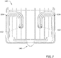
FIG. 7 is a bottom view of the cleaning tray fromFIG. 4 . -
FIG. 8 is a cross-sectional view taken through line VIII-VIII ofFIG. 4 . -
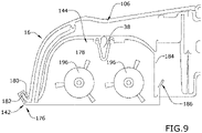
FIG. 9 is a cross-sectional view through the extraction cleaner ofFIG. 2 docked with another cleaning tray according to various aspects described herein. -
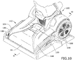
FIG. 10 is a perspective view of an extraction cleaner docked with another cleaning tray according to various aspects described herein. -
FIG. 11 is a cross-sectional view taken through line XI-XI ofFIG. 10 . -
FIG. 12 is an exploded view of the cleaning tray ofFIG. 10 . -
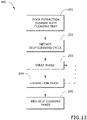
FIG. 13 is a flow chart depicting a self-cleaning method for an upright extraction cleaner using a cleaning tray. -
FIG. 14 is a schematic view of another extraction surface cleaning apparatus in the form of a deep cleaning robot according to various aspects described herein. -
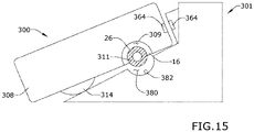
FIG. 15 is a perspective view of the deep cleaning robot ofFIG. 14 docked with a self-cleaning docking station according to various aspects described herein. -
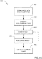
FIG. 16 is a flow chart depicting a self-cleaning method for the deep cleaning robot ofFIG. 15 using the docking station ofFIG. 15 . -
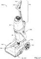
FIG. 17 is a perspective view of another extraction surface cleaning apparatus in the form of an upright extraction cleaner according to various aspects described herein. -
FIG. 18 is a cross-sectional view through a centerline of a base assembly of the extraction cleaner ofFIG. 17 . -
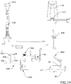
FIG. 19 is a schematic view of a fluid delivery system of the extraction cleaner ofFIG. 17 . -
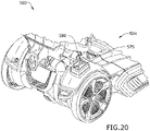
FIG. 20 is a rear perspective view of the base assembly of the extraction cleaner ofFIG. 17 to show a control pedal for a nozzle cleaning feature. -
FIG. 21 is a sectional view through a push-push flow control valve operably coupled with the control pedal fromFIG. 20 , where the valve is shown in a closed position. -
FIG. 22 is a sectional view similar toFIG. 21 , where the valve is shown in an open position. -
FIG. 23 is a partially exploded and partial sectional view through the valve ofFIG. 21 . - The disclosure generally relates to features and improvements for extraction cleaners for floor surfaces that have fluid delivery and recovery capabilities. In particular, the features and improvements relate to cleaning and maintaining such extraction cleaners.
-
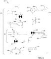
FIG. 1 is a schematic view of various functional systems of a surface cleaning apparatus in the form of anextraction cleaner 10. The functional systems of theextraction cleaner 10 can be arranged into any desired configuration, such as an upright extraction device having a base and an upright body for directing the base across the surface to be cleaned, a canister device having a cleaning implement connected to a wheeled base by a vacuum hose, a portable extractor adapted to be hand carried by a user for cleaning relatively small areas, or a commercial extractor. Any of the aforementioned extraction cleaners can be adapted to include a flexible vacuum hose, which can form a portion of the working air conduit between a nozzle and the suction source. - The
extraction cleaner 10 can include afluid delivery system 12 for storing cleaning fluid and delivering the cleaning fluid to the surface to be cleaned and arecovery system 14 for removing the spent cleaning fluid and debris from the surface to be cleaned and storing the spent cleaning fluid and debris. - The
recovery system 14 can include asuction nozzle 16, asuction source 18 in fluid communication with thesuction nozzle 16 for generating a working air stream, and arecovery container 20 for separating and collecting fluid and debris from the working airstream for later disposal. Aseparator 21 can be formed in a portion of therecovery container 20 for separating fluid and entrained debris from the working airstream. - The
suction source 18 is provided in fluid communication with therecovery container 20. The suction source is illustrated herein as a motor/fan assembly 19 that can be electrically coupled to apower source 22, such as a battery or by a power cord plugged into a household electrical outlet. Asuction power switch 24 between the motor/fan assembly 19 and thepower source 22 can be selectively closed by the user, thereby activating the motor/fan assembly 19. - The
suction nozzle 16 can be provided on a base or cleaning head adapted to move over the surface to be cleaned. Anagitator 26 can be provided adjacent to thesuction nozzle 16 for agitating the surface to be cleaned so that the debris is more easily ingested into thesuction nozzle 16. Some examples of agitators include, but are not limited to, a horizontally-rotating brushroll, dual horizontally-rotating brushrolls, one or more vertically-rotating brushrolls, or a stationary brush. - The
extraction cleaner 10 can also be provided with above-the-floor cleaning features. Anaccessory hose 28 can be selectively fluidly coupled to the motor/fan assembly 19 for above-the-floor cleaning using an above-thefloor accessory tool 30 with its own suction inlet. Adiverter assembly 32 can be selectively switched between on-the-floor and above-the floor cleaning by diverting fluid communication between either thesuction nozzle 16 or theaccessory hose 28 with the motor/fan assembly 19. Theaccessory hose 28 can also communicate with thefluid delivery system 12 to selectively deliver cleaning fluid. - The
fluid delivery system 12 can include at least onefluid container 34 for storing a supply of fluid. The fluid can comprise one or more of any suitable cleaning fluids, including, but not limited to, water, compositions, concentrated detergent, diluted detergent, etc., and mixtures thereof. For example, the fluid can comprise a mixture of water and concentrated detergent. - The
fluid delivery system 12 can further comprise aflow control system 36 for controlling the flow of fluid from thesupply container 34 to at least onefluid distributor 38. In one configuration, theflow control system 36 can comprise apump 40 which pressurizes thesystem 12 and aflow control valve 42 which controls the delivery of fluid to thedistributor 38. Anactuator 44 can be provided to actuate theflow control system 36 and dispense fluid to thedistributor 38. Theactuator 44 can be operably coupled to thevalve 42 such that pressing theactuator 44 will open thevalve 42. Thevalve 42 can be electrically actuated, such as by providing anelectrical switch 46 between thevalve 42 and thepower source 22 that is selectively closed when theactuator 44 is pressed, thereby powering thevalve 42 to move to an open position. In one example, thevalve 42 can be a solenoid valve. Thepump 40 can also be coupled with thepower source 22. In one example, thepump 40 can be a centrifugal pump. In another example, thepump 40 can be a solenoid pump. - The
fluid distributor 38 can include at least onedistributor outlet 48 for delivering fluid to the surface to be cleaned. The at least onedistributor outlet 48 can be positioned to deliver fluid directly to the surface to be cleaned, or indirectly by delivering fluid onto theagitator 26. The at least onedistributor outlet 48 can comprise any structure, such as a nozzle or spray tip;multiple outlets 48 can also be provided. As illustrated inFIG. 1 , thedistributor 38 can comprisemultiple sprayers 48 which distribute cleaning fluid to the surface to be cleaned. For above-the-floor cleaning, thecleaning tool 30 can include an auxiliary distributor (not shown) coupled with thefluid delivery system 12. - Optionally, a
heater 50 can be provided for heating the cleaning fluid prior to delivering the cleaning fluid to the surface to be cleaned. In the example illustrated inFIG. 1 , an in-line heater 50 can be located downstream of thecontainer 34 and upstream of thepump 40. Other types ofheaters 50 can also be used. In yet another example, the cleaning fluid can be heated using exhaust air from a motor-cooling pathway for the motor/fan assembly 19. - As another option, the fluid delivery system can be provided with an
additional container 52 for storing a cleaning fluid. For example, thefirst container 34 can store water and thesecond container 52 can store a cleaning agent such as detergent. Thecontainers first container 34 can be a bladder that is provided within therecovery container 20. Alternatively, a single container can define multiple chambers for different fluids. - In the case where
multiple containers flow control system 36 can further be provided with amixing system 54 for controlling the composition of the cleaning fluid that is delivered to the surface. The composition of the cleaning fluid can be determined by the ratio of cleaning fluids mixed together by the mixing system. As shown herein, the mixingsystem 54 includes a mixingmanifold 56 that selectively receives fluid from one or both of thecontainers valve 58 is fluidly coupled with an outlet of thesecond container 52, whereby when mixingvalve 58 is open, the second cleaning fluid will flow to the mixingmanifold 56. By controlling the orifice of the mixingvalve 58 or the time that the mixingvalve 58 is open, the composition of the cleaning fluid that is delivered to the surface can be selected. - In yet another configuration of the
fluid delivery system 12, thepump 40 can be eliminated and theflow control system 36 can comprise a gravity-feed system having a valve fluidly coupled with an outlet of the container(s) 34, 52, whereby when valve is open, fluid will flow under the force of gravity to thedistributor 38. The valve can be mechanically actuated or electrically actuated, as described above. - The
extraction cleaner 10 shown inFIG. 1 can be used to effectively remove debris and fluid from the surface to be cleaned in accordance with the following method. The sequence of steps discussed is for illustrative purposes only and is not meant to limit the method in any way as it is understood that the steps may proceed in a different logical order, additional or intervening steps may be included, or described steps may be divided into multiple steps, without detracting from the disclosure. - In operation, the
extraction cleaner 10 is prepared for use by coupling theextraction cleaner 10 to thepower source 22, and by filling thefirst container 34, and optionally thesecond container 52, with cleaning fluid. Cleaning fluid is selectively delivered to the surface to be cleaned via thefluid delivery system 12 by user-activation of theactuator 44, while theextraction cleaner 10 is moved back and forth over the surface. Theagitator 26 can simultaneously agitate the cleaning fluid into the surface to be cleaned. During operation of therecovery system 14, theextraction cleaner 10 draws in fluid and debris-laden working air through thesuction nozzle 16 orcleaning tool 30, depending on the position of thediverter assembly 32, and into thedownstream recovery container 20 where the fluid debris is substantially separated from the working air. The airstream then passes through the motor/fan assembly 19 prior to being exhausted from theextraction cleaner 10. Therecovery container 20 can be periodically emptied of collected fluid and debris. -
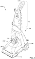
FIG. 2 is a perspective view of a surface cleaning apparatus in the form of an upright deep cleaner or extraction cleaner 100 according to various aspects described herein. The upright extraction cleaner can incorporate the systems and components shown inFIG. 1 , including thefluid delivery system 12 for storing and delivering a cleaning fluid to the surface to be cleaned and therecovery system 14 for extracting and storing the dispensed cleaning fluid, dirt and debris from the surface to be cleaned. As illustrated herein, theextraction cleaner 100 is an upright extraction cleaner having a housing that includes anupright assembly 102 that is pivotally connected to abase assembly 104 for directing thebase assembly 104 across the surface to be cleaned. - For purposes of description related to the figures, the terms "upper," "lower," "right," "left," "rear," "front," "vertical," "horizontal," "inner," "outer," and derivatives thereof shall relate to the
extraction cleaner 100 as oriented inFIG. 2 from the perspective of a user behind theextraction cleaner 100, which defines the rear of theextraction cleaner 100. However, it is to be understood that the disclosure may assume various alternative orientations, except where expressly specified to the contrary. - The various systems and components schematically described for
FIG. 1 , including thefluid delivery system 12 andfluid recovery system 14 can be supported by either or both the base assembly and the upright assembly. Thebase assembly 104 has been illustrated as including abase housing 106 supporting components of thefluid delivery system 12 and therecovery system 14, including, but not limited to, thesuction nozzle 16, theagitator 26, thepump 40, and at least onefluid distributor 38. Thebase assembly 104 can also support therecovery container 20 at a forward portion thereof, forward being defined as relative to the mounting location of theupright assembly 102 on thebase assembly 104, and the fluid container or supply tank, which is not visible inFIG. 2 , at a rearward portion thereof.Wheels 108 at least partially support the base housing for movement over the surface to be cleaned. An additional agitator in the form of stationary edge brushes 110 may also be provided on the base housing. The motor/fan assembly 19 (FIG. 1 ) can also be positioned within thebase assembly 104, in fluid communication with therecovery container 20. Theupright assembly 102 has anelongated housing 112 extending upwardly frombase assembly 104 that is provided with ahand grip 114 at one end that can be used for maneuvering theextraction cleaner 100 over a surface to be cleaned. Theelongated housing 112 can store an accessory hose 116 (shown inFIG. 3 ) when not in use for above-the-floor cleaning. Additional details of theextraction cleaner 100 are disclosed inU.S. Patent No. 7,784,148 , which is incorporated herein by reference in its entirety. -
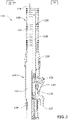
FIG. 3 illustrates that theaccessory hose 28 includes aflexible hose conduit 118, a flexiblefluid delivery conduit 120, a hose coupler (not shown) at one end of thehose conduit 118 which couples to theextraction cleaner 100 to place the hose in fluid communication with the fluid delivery andrecovery systems wand 122 at the opposite end of thehose conduit 118 for selectively coupling an accessory tool, such ascleaning tool 30 shown inFIG. 1 . Thewand 122 defines aninlet 124 of theaccessory hose 116. Only a portion of the length of thehose conduit 118 is shown inFIG. 3 for clarity, as indicated by the break lines through thehose conduit 118. - The
flexible hose conduit 118 can define anairflow pathway 126 and can carry the flexiblefluid delivery conduit 120 within theairflow pathway 126. Alternatively, thefluid delivery conduit 120 can extend externally to theairflow pathway 126. Theairflow pathway 126 is configured to be coupled with therecovery container 20, and thefluid delivery conduit 120, which defines afluid delivery pathway 128, is configured to be coupled with thesupply container 34. - The
wand 122 includes ahousing 130 with anairflow pathway 132 having anairflow connector 134 which fluidly couples with theairflow pathway 126 of thehose conduit 118, and afluid delivery pathway 136 having afluid connector 137 which fluidly couples with thefluid delivery pathway 128 of thedelivery conduit 120. Avalve 138 can be provided in thefluid delivery pathway 136 for controlling the flow of cleaning fluid to thefluid connector 137. Thevalve 138 can be controlled by the user via a valve actuator, such as atrigger 140 provided on the housing of thewand 122. -
FIG. 4 is a perspective view of the extraction cleaner ofFIG. 2 docked with a body forming acleaning tray 142 according to non-limiting aspects of the disclosure. Upright extraction cleaners can get very dirty, particularly in the brush chamber and extraction pathway, and can be difficult for the user to clean. A self-cleaning system and method using the cleaning tray shown inFIG. 4 is provided for theextraction cleaner 100, which saves the user considerable time and may lead to more frequent use of theextraction cleaner 100. - The
extraction cleaner 100 can have an integrated self-cleaning cycle configured to be run when theextraction cleaner 100 is docked with the cleaningtray 142 as shown inFIG. 4 . The cleaningtray 142 is configured to at least partially surround at least one of thesuction nozzle 16 andagitator 26. More specifically, the cleaningtray 142 can create a sealedcleaning pathway 146 between abrush chamber 144 andsuction nozzle 16 when installed. The user can then engage the self-cleaning cycle, which washes out thebrush chamber 144 via the sealedcleaning pathway 146. The self-cleaning cycle can utilize theaccessory hose 116 discussed forFIG. 3 in addition to thecleaning tray 142. - Referring to
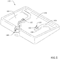
FIGS. 5-7 , thetray 142 is configured to support a portion of theextraction cleaner 100 thereon, and includes ahose receiver 148 at one end for fluidly coupling with theaccessory hose 116, which is coupled at the opposite end with theextraction cleaner 100 as described above, and afluid delivery manifold 150 fluidly connected to thehose receiver 148 at one end. Thetray 142 also includes one or more upward facingspray nozzles 152 fluidly connected to themanifold 150. The manifold 150 can includemultiple conduits 154 extending from thehose receiver 148 tomultiple spray nozzles 152. As shown twoconduits 154 extend from thehose receiver 148 along abottom side 156 of thetray 142, and each has anoutlet 158 fluidly coupled with aspray nozzle 152. The illustratedconduits 154 are flexible hoses fastened within a channel 160 on the bottom of thetray 142. Alternatively, integrally-moldedconduits 154 can be provided within thetray 142 itself. Thespray nozzles 152 have at least onespray nozzle outlet 162 oriented to direct a spray of cleaning fluid upwardly. It is contemplated that thetray 142 can form areservoir 164 which collects sprayed cleaning fluid. -
FIG. 8 is a cross-sectional view of the extraction cleaner docked with the cleaning tray. Thereservoir 164 of thetray 142 holds the collected cleaning fluid in the vicinity of thesuction nozzle 16, whereby thesuction nozzle 16 can draw the collected cleaning fluid into therecovery container 20. This also serves to flush out arecovery pathway 165 between thesuction nozzle 16 and therecovery container 20. It is noted that thesuction nozzle 16, rather than thehose 116, is in fluid communication with the motor/fan assembly 19 (FIG. 1 ) during self-cleaning; for example, the diverter assembly 32 (FIG. 1 ) of theextraction cleaner 100 is switched to on-the-floor cleaning. - The
tray 142 can be configured to physically support a portion of theextraction cleaner 100 in engagement with thecollection reservoir 164, and can include aforward support 166 for engaging the front of thesuction nozzle 16 and arearward support 168 which engages the bottom of thebase housing 106 behind thebrush chamber 144. Thetray 142 can also be used when storing theextraction cleaner 100 after use or self-cleaning, and can catch any drips from theextraction cleaner 100. - The front portion of the
base housing 106 of theextraction cleaner 100, which includes at least thesuction nozzle 16 and thebrush chamber 144, rests on top of thetray 142 in the illustrated example. - The
hose receiver 148 includes afluid connector coupler 170 in fluid communication with the manifold 150 that receives thefluid connector 137 of thehose 116. Atrigger actuator 172 is associated with thefluid connector coupler 170, and is configured to depress thetrigger 140 when thefluid connector 137 is received in thecoupler 170. Receipt of thefluid connector 137 in thefluid connector coupler 170 thereby simultaneously places thefluid connector 137 in fluid communication with the manifold 150 and opens thevalve 138 to open thefluid delivery pathway 128. Thehose receiver 148 further includes anairflow connector coupler 174 that receives theairflow connector 134 of thehose 116 to support thehose 116 in a substantially upright position on thetray 142. - Alternatively,
FIG. 9 illustrates that thetray 142 can be configured as a snap-fit cover 176, similar to a lid of a plastic storage container, which mounts to the bottom of thebase housing 106 and encloses thebrush chamber 144 andsuction nozzle 16, thereby creating acleaning chamber 178 for flushing thesuction nozzle 16 andbrush chamber 144. Thetray 142 can comprise a retainer such as ahook 180 on a forward portion that is configured to mount to a corresponding feature on thesuction nozzle 16, such as a mountinglip 182, on a lower, forward portion of thebase housing 106. Thetray 142 can further comprise flexible, resilientvertical walls 184 that can be press fit onto thebase housing 106 for sealing around the perimeter of thebase housing 106. A rear portion of thetray 142 can comprise apull tab 186 for releasing thetray 142 from thebase housing 106. A user can apply downward force on thepull tab 186 to slide thevertical walls 184 off thebase housing 106 while pivoting thetray 142 about thehook 180 to disengage the mountinglip 182 and remove thetray 142 from thebase housing 106. - In an alternate aspect of the present disclosure shown in
FIGS. 10-12 , thetray 142 can be configured as a cleaning tray that physically supports an entire extraction cleaner. The cleaning tray is shown in use with an extraction cleaner as disclosed inU.S. Patent Application Publication No. 2017/0071434, published March 16, 2017 , which is incorporated herein by reference in its entirety, but can alternatively be used with the extraction cleaner ofFIG. 1 or2 , or other extraction cleaners. - More specifically, a base of the
extraction cleaner 100 can be seated in thetray 142. As illustrated inFIG. 10 , the body forming thetray 142 can have a recessedportion 188 configured to at least partially surround at least one of thesuction nozzle 16 oragitator 26. In addition, the recessedportion 188 can sealingly receive thesuction nozzle 16 andagitator 26, such as by sealingly receiving thebrush chamber 144. Thetray 142 can also includeguide walls 189 extending upwardly and configured to align thebase assembly 104 of theextraction cleaner 100 within thetray 142. A rear portion of thetray 142 can comprisewheel wells 198 for receiving therear wheels 108 of theextraction cleaner 100. - Turning to
FIG. 11 , a side sectional view along line XI-XI is illustrated wherein aspects of thecleaning tray 142 can be seen in further detail. The recessedportion 188 can fluidly isolate, or seal, thesuction nozzle 16 and at least oneagitator 26, illustrated asbrushrolls 196 within thebrush chamber 144. - The recessed
portion 188 can further be configured to receive abrush cleaning insert 190. Thebrush cleaning insert 190 can include any suitable form, including arectangular base plate 192 having a plurality ofprojections 194 such as teeth, nubs or tines extending from thebase plate 192 and configured to contact the agitator. In the illustrated example theprojections 194 can engage the bristles ofbrushrolls 196 in thebrush chamber 144. In addition, while several rows of the same type ofprojection 194 are illustrated it will be understood that any of combination or placement ofprojections 194 can be utilized on thebrush cleaning insert 190. - In operation, the
extraction cleaner 100 can be docked within the cleaningtray 142. The docking can include aligning at least one of thesuction nozzle 16 orbrush chamber 144 over the recessedportion 188 within theguide walls 189. The docking can also include aligning thewheels 108 within thewheel wells 198. Once docked, cleaning fluid from the supply container 34 (FIG. 1 ) can be distributed to the recessedportion 188 via thefluid distributor 38, such as by spraying the cleaning fluid through at least onedistributor outlet 48. Thesuction nozzle 16 can be operated to suction the cleaning fluid from the recessedportion 188 to the recovery container 20 (FIG. 1 ), thereby cleaning thesuction nozzle 16. In addition, thebrushrolls 196 can rotate during either or both of the distributing/spraying phase or the suctioning phase. Theprojections 194 can scrape hair and other debris off thebrushrolls 196 as thebrushrolls 196 rotate during a cleaning cycle. - Referring now to
FIG. 12 , it is further contemplated that theinsert 190 can be removable from thetray 142 for ease of cleaning and replacement. Thebase plate 192 can include aprotrusion 191 extending from a periphery of thebase plate 192. Thetray 142 can include acorresponding notch 193 configured to receive theprotrusion 191. The coupledprotrusion 191 and notch 193 can at least partially hold theinsert 190 in place within thetray 142 when assembled. In this manner theinsert 190 can be selectively received within at least a portion of the recessedportion 188 and configured to engage the agitator, such as the brushrolls 196 (FIG. 11 ). In another non-limiting example, thebase plate 192 can be configured to snap fit into the recessed portion. - The
projections 194 are schematically illustrated as essentially rectangular nubs, and it should be understood that any desired geometric profile can be utilized for theprojections 194, including flexible bristles, teeth, pointed/triangular projections, or the like, or combinations thereof. In addition, a rear wall of thetray 142 can optionally comprise atool recess 199 for mounting additional cleaning tools or accessories. One such example is anozzle cleanout tool 199T, more fully disclosed inU.S. Patent Application Publication No. 2016/0270620, published September 22, 2016 , which is incorporated herein by reference in its entirety. - The
tray 142 shown inFIGS. 10-12 is not configured to utilize theaccessory hose 116 to deliver cleaning fluid as in the previous aspects of the disclosure, and thetray 142 does not include a fluid delivery manifold or spray nozzles. Instead, thetray 142 of the present aspect of the disclosure encloses thebrush chamber 144 andsuction nozzle 16 forming a sealedcleaning pathway 146 to thedownstream recovery container 20 and fluid is dispensed from adistributor 38 within thebrush chamber 144 to wash out thebrush chamber 144,suction nozzle 16, andairflow pathway 126 between thesuction nozzle 16 andrecovery container 20. -
FIG. 13 depicts one aspect of the disclosure of a self-cleaningmethod 200 for anupright extraction cleaner 100 using thecleaning tray 142. In use, a user at 201 docks theextraction cleaner 100 with the cleaningtray 142. The docking may include parking thebase housing 106 of theextraction cleaner 100 on thecleaning tray 142 and inserting theaccessory hose 116 into thehose receiver 148. The cleaningtray 142 creates a sealed cleaning pathway between thebrush chamber 144 and thesuction nozzle 16. The user can then initiate at 202 a self-cleaning cycle of theextraction cleaner 100. The self-cleaning cycle can be manual, with the user initiating the cycle by manually energizing theextraction cleaner 100 and depressing atrigger 140 on thehand grip 114 to distribute cleaning fluid. Alternatively, the self-cleaning cycle can be automated so that the cleaning cycle is controlled by a microcontroller on theextraction cleaner 100. In this case a user-engageable button or switch may be pressed by a user to initiate the automated self-cleaning cycle. - The self-cleaning cycle may begin at 203 with at least one spraying phase in which cleaning solution from the
supply container 34 is delivered to the specially-aimedspray nozzles 152 on thecleaning tray 142 that spray thebrush chamber 144. Because thehose receiver 148 depresses thetrigger 140 on thewand 122 of theaccessory hose 116, the pressurized fluid flow through theconduits 154 is sprayed through thespray nozzles 152 to wash off debris and hair from inside thebrush chamber 144, including thebrushrolls 196. The self-cleaning cycle may use the same cleaning fluid normally used by theextraction cleaner 100 for surface cleaning, or may use a different detergent focused on cleaning thefluid recovery system 14 of theextraction cleaner 100. - The self-cleaning cycle may also include at least one extraction phase at 204 in which the
suction source 18 is actuated to suction up the cleaning fluid via thesuction nozzle 16. During the extraction phase, the cleaning fluid and debris from thecollection reservoir 164 in thetray 142 is sucked through thesuction nozzle 16 and the downstream fluid recovery path. The flushing action also cleans the entire fluid recovery path of theextraction cleaner 100, including thesuction nozzle 16 and downstream conduits. - The extraction phase of the cleaning cycle can occur simultaneously with the spraying phase or after the spraying phase is complete. In yet another alternative, the extraction phase can initiate after a timed delay from the initiation of the spraying phase. The self-cleaning cycle can optionally repeat the spraying and extraction phases one or more times. For example, the self-cleaning cycle can be configured to repeat the spraying and extraction phases three times before the end of the cycle. The end of the self-cleaning cycle at 205 may be time-dependent, or may continue until the
recovery container 20 is full or thesupply container 34 is empty. During the spraying phase and/or the extraction phase, thebrushrolls 196 can rotate to propel fluid within thebrush chamber 144 and provide agitation that enhances the cleaning effect. - The self-cleaning system and method is described above with reference to an upright extraction cleaner, but are also generally applicable to other types of extraction cleaners. For example, the self-cleaning system and method can be applied to an autonomous a deep cleaning robot.
FIG. 14 is a schematic view of one example of such adeep cleaning robot 300. - The
deep cleaning robot 300 mounts the components of various functional systems of theextraction cleaner 10 in an autonomously moveable unit or housing, including components of afluid delivery system 12 for storing cleaning fluid and delivering the cleaning fluid to the surface to be cleaned, afluid recovery system 14 for removing the cleaning fluid and debris from the surface to be cleaned and storing the recovered cleaning fluid and debris, adrive system 310 for autonomously moving the robot over the surface to be cleaned, and a navigation/mapping system 320 for guiding the movement of therobot 300 over the surface to be cleaned, generating and storing maps of the surface to be cleaned, and recording status or other environmental variable information. Therobot 300 includes a main housing adapted to selectively mount components of the systems to form a unitary movable device. - A
controller 350 is operably coupled with the various function systems ofrobot 300 for controlling its operation. The controller can be a microcontroller unit (MCU) that contains at least one central processing unit (CPU). - As described above, the
fluid delivery system 12 can include asupply container 34 for storing a supply of cleaning fluid and afluid distributor 38 in fluid communication with thesupply container 34 for depositing a cleaning fluid onto the surface. The cleaning fluid can be a liquid such as water or a cleaning solution specifically formulated for carpet or hard surface cleaning. Thefluid distributor 38 can be one ormore spray nozzle 302 provided on the housing of therobot 300. Alternatively, thefluid distributor 38 can be a manifold having multiple outlets. Apump 40 driven by a pump motor 304 is provided in the fluid pathway between thesupply container 34 and thedistributor 38 to control the flow of fluid to thedistributor 38. Various combinations of optional components can be incorporated into the fluid delivery system as is commonly known in the art, such as a heater for heating the cleaning fluid before it is applied to the surface or one more fluid control and mixing valves. - At least one agitator or
brush 311 can be provided for agitating the surface to be cleaned onto which fluid has been dispensed. The brush can be a brushroll mounted for rotation about a substantially horizontal axis, relative to the surface over which therobot 300 moves. A drive assembly including a separate,dedicated brush motor 312 can be provided within therobot 300 to drive thebrush 311. Alternatively, thebrush 311 can be driven by the vacuum motor 313. Other aspects of the disclosure of agitators are also possible, including one or more stationary or non-moving brushes, or one or more brushes that rotate about a substantially vertical axis. - The fluid recovery system 14 (
FIG. 1 ) can include an extraction path through therobot 300 having an air inlet and an air outlet, an extraction or suction nozzle 16 (FIG. 15 ) which is positioned to confront the surface to be cleaned and defines the air inlet, arecovery container 20 for receiving dirt and liquid removed from the surface for later disposal, and asuction source 18 in fluid communication with the suction nozzle and the recovery container for generating a working air stream through the extraction path. Thesuction source 18 can be a vacuum motor 313 fluidly upstream of the air outlet, and can define a portion of the extraction path. Therecovery container 20 can also define a portion of the extraction path, and can comprise an air/liquid separator for separating liquid from the working airstream. Optionally, a pre-motor filter and/or a post-motor filter (not shown) can be provided as well. - While not shown, a squeegee can be provided on the
housing 308, adjacent thesuction nozzle 16, and is configured to contact the surface as therobot 300 moves across the surface to be cleaned. The squeegee wipes residual liquid from the surface to be cleaned so that it can be drawn into the fluid recovery pathway via thesuction nozzle 16, thereby leaving a moisture and streak-free finish on the surface to be cleaned. - The
drive system 310 can include drivewheels 314 for driving therobot 300 across a surface to be cleaned. Thedrive wheels 314 can be operated by acommon drive motor 315 or individual drive motors coupled with thedrive wheels 314 by a transmission, which may include a gear train assembly or another suitable transmission. Thedrive system 310 can receive inputs from thecontroller 350 for driving therobot 300 across a floor, based on inputs from the navigation/mapping system 320. Thedrive wheels 314 can be driven in in a forward or reverse direction in order to move therobot 300 forwardly or rearwardly. Furthermore, thedrive wheels 314 can be operated simultaneously or individually in order to turn therobot 300 in a desired direction. - The
controller 350 can receive input from the navigation/mapping system 320 for directing thedrive system 310 to move therobot 300 over the surface to be cleaned. The navigation/mapping system 320 can include amemory 322 that stores maps for navigation and inputs from various sensors, which is used to guide the movement of therobot 300. For example,wheel encoders 331 can be placed on the drive shafts of thewheel motors 315, and are configured to measure the distance traveled. This measurement can be provided as input to thecontroller 350. -
Motor drivers 305 can be provided for controlling the pump motor 304,brush motor 312, vacuum motor 313, and wheel motors 317 and acts as an interface between thecontroller 350 and themotors 304, 312, 313, 317. Themotor drivers 305 may be an integrated circuit chip (IC). For the wheel motors 317, onemotor driver 305 can controller the motors 317 simultaneously. - The
motor drivers 305 for the pump motor 304,brush motor 312, vacuum motor 313, and wheel motors 317 can be electrically coupled to abattery management system 360 which includes a rechargeable battery orbattery pack 362. In one example, thebattery pack 362 can include lithium ion batteries. Charging contacts for thebattery pack 362 can be provided on the exterior of thehousing 308. Adocking station 301 for receiving therobot 300 for charging can be provided with corresponding charging contacts. In one example, the charging contacts provided on therobot 300 may be an electrical connector such as a DC jack. - The controller is further operably coupled with a user interface (UI) for receiving inputs from a user. The
user interface 370 can be used to select an operation cycle for therobot 300 or otherwise control the operation of therobot 300. The user interface can have adisplay 372, such as an LED display, for providing visual notifications to the user. Adisplay driver 374 can be provided for controlling thedisplay 374, and acts as an interface between thecontroller 350 and thedisplay 372. Thedisplay driver 374 may be an integrated circuit chip (IC). Therobot 300 can further be provided with a speaker (not shown) for providing audible notifications to the user. - The
user interface 370 can further have one ormore switches 376 that are actuated by the user to provide input to thecontroller 350 to control the operation of various components of therobot 300. Aswitch driver 378 can be provided for controlling theswitch 376, and acts as an interface between thecontroller 350 and theswitch 376. - The
controller 350 can further be operably coupled with various sensors for receiving input about the environment and can use the sensor input to control the operation of therobot 300. The sensor input can further be stored in thememory 322 and/or used to develop maps for navigation. Some exemplary sensors are illustrated inFIG. 14 . It will be understood that not all sensors shown may be provided, additional sensors not shown may be provided, and that the sensors can be provided in any combination. - The
robot 300 can include a positioning orlocalization system 330 having one or more sensors determining the position of therobot 300 relative to objects, including thewheel encoders 331. The localization system can include one or more infrared (IR)obstacle sensors 332 for distance and position sensing. Theobstacle sensors 332 are mounted to the housing of theautonomous robot 300, such as at the front of therobot 300 to determine the distance to obstacles in front of therobot 300. Input from theobstacle sensors 332 can be used to slow down and/or adjust the course of therobot 300 when objects are detected. -
Bump sensors 333 can also be provided for determining front or side impacts to therobot 300. Thebump sensors 333 may be integrated with a bumper on thehousing 308 of therobot 300. Output signals from thebump sensors 333 provide inputs to the controller for selecting an obstacle avoidance algorithm. - In addition to the obstacle and bump sensors, the
localization system 330 can include additional sensors, including aside wall sensor 334, one ormore cliff sensors 335, and/or anaccelerometer 336. Theside wall sensor 334 can also be in the form of a wall following sensor located near the side of therobot 300, and can also include a side-facing optical position sensor that provides distance feedback and controls therobot 300 so that therobot 300 can follow near a wall without contacting the wall. Thecliff sensors 335 can be bottom-facing optical position sensors that provide distance feedback and control therobot 300 so that therobot 300 can avoid excessive drops such as stairwells or ledges. In addition to optical sensors, theside wall sensors 334 andcliff sensors 335 can be mechanical or ultrasonic sensors. - The
accelerometer 336 is an integrated inertial sensor located on the controller and can be a nine-axis gyroscope or accelerometer to sense linear, rotational and magnetic field acceleration. Theaccelerometer 336 can use acceleration input data to calculate and communicate change in velocity and pose to the controller for navigating therobot 300 around the surface to be cleaned. - The
robot 300 can further include one or more lift-upsensors 337, which detect when therobot 300 is lifted off the surface to be cleaned, such as when the user picks up therobot 300. This information is provided as an input to thecontroller 350, which will halt operation of the pump motor 304,brush motor 312, vacuum motor 313, and/or wheel motors 317. The lift-upsensors 337 may also detect when therobot 300 is in contact with the surface to be cleaned, such as when the user places therobot 300 back on the ground; upon such input, thecontroller 350 may resume operation of the pump motor 304,brush motor 312, vacuum motor 313, and wheel motors 317. - While not shown, the
robot 300 can optionally include one or more sensors for detecting the presence of the supply andrecovery containers supply container 34 and therecovery container 20 can be provided. This information is provided as an input to thecontroller 350, which may prevent operation of therobot 300 until the supply andrecovery containers controller 350 may also direct thedisplay 372 to provide a notification to the user that thesupply container 34 orrecovery container 20 is missing. - The
robot 300 can further include one or morefloor condition sensors 338 for detecting a condition of the surface to be cleaned. For example, therobot 300 can be provided with an infrared dirt sensor, a stain sensor, an odor sensor, and/or a wet mess sensor. Thefloor condition sensors 338 provide input to thecontroller 350, which may direct operation of therobot 300 based on the condition of the surface to be cleaned, such as by selecting or modifying a cleaning cycle. - An
artificial barrier system 340 can also be provided for containing therobot 300 within a user-determined boundary. Theartificial barrier system 340 can include anartificial barrier generator 342 that comprises a housing with at least one sonic receiver for receiving a sonic signal from therobot 300 and at least one IR transmitter for emitting an encoded IR beam towards a predetermined direction for a predetermined period of time. Theartificial barrier generator 342 can be battery-powered by rechargeable or non-rechargeable batteries. In one aspect of the disclosure, the sonic receiver can comprise a microphone configured to sense a predetermined threshold sound level, which corresponds with the sound level emitted by therobot 300 when it is within a predetermined distance away from the artificial barrier generator. Optionally, theartificial barrier generator 342 can further comprise a plurality of IR emitters near the base of the housing configured to emit a plurality of short field IR beams around the base of the artificial barrier generator housing. Theartificial barrier generator 342 can be configured to selectively emit one or more IR beams for a predetermined period of time, but only after the microphone senses the threshold sound level, which indicates therobot 300 is nearby. Thus, theartificial barrier generator 342 is able to conserve power by emitting IR beams only when therobot 300 is in the vicinity of the artificial barrier generator. - The
robot 300 can have a plurality ofIR transceivers 344 around the perimeter of therobot 300 to sense the IR signals emitted from theartificial barrier generator 342 and output corresponding signals to the controller, which can adjust drive wheel control parameters to adjust the position of therobot 300 to avoid the boundaries established by the artificial barrier encoded IR beam and the short field IR beams. This prevents therobot 300 from crossing the artificial boundary and/or colliding with the artificial barrier generator housing. TheIR transceivers 344 can also be used to guide therobot 300 toward thedocking station 301. - In operation, sound emitted from the
robot 300 greater than a predetermined threshold sound level is sensed by the microphone and triggers theartificial barrier generator 342 to emit one or more encoded IR beams as described previously for a predetermined period of time. The IR transceivers 344 on therobot 300 sense the IR beams and output signals to thecontroller 350, which then manipulates thedrive system 310 to adjust the position of therobot 300 to avoid the border established by theartificial barrier system 340 while continuing to perform a cleaning operation on the surface to be cleaned. -
FIG. 15 shows adeep cleaning robot 300 that includes the systems and components shown inFIG. 14 docked with a self-cleaningdocking station 301 according to non-limiting aspects of the disclosure. Like upright extraction cleaners, deep cleaning robots can get very dirty, particularly in the brush chamber and extraction pathway, and can be difficult for the user to clean. A self-cleaning system and method using the docking station shown inFIG. 15 is provided for thedeep cleaning robot 300, which saves the user considerable time and may lead to more frequent use of thedeep cleaning robot 300. - The
deep cleaning robot 300 can have an integrated self-cleaning mode or cycle configured to be run when thedeep cleaning robot 300 is docked with the docking station as shown inFIG. 15 . The docking station is configured to create a sealed cleaning pathway between abrush chamber 309 andsuction nozzle 16 when therobot 300 is docked therein. The user can then engage the self-cleaning cycle, which washes out thebrush chamber 309 via the sealed cleaning pathway. - The docking station can include a recessed portion in the form of a
sump 380 for collecting excess liquid and guiding it towards thesuction nozzle 16 for eventual extraction. Thesump 380 can be configured to align with thebrush chamber 309 of therobot 300, and can include one ormore spray nozzles 382 for spraying cleaning fluid into thebrush chamber 309. Thespray nozzles 382 can be in communication with a source of cleaning fluid stored on thedocking station 301, or can be coupled with thefluid delivery system 12 of therobot 300 when docked and be supplied with fluid from thesupply container 34. - The
docking station 301 can include a ramp 384 which therobot 300 drives up to couple with chargingcontacts 364 for recharging the battery pack 362 (FIG. 14 ). Thedocking station 301 itself can be connected to external power to charge thebattery pack 362. Thedocking station 301 can be configured such that when therobot 300 is docked for charging, it is also in correct alignment with thesump 380 for self-cleaning. Thedocking station 301 can also be used when storing therobot 300 after use or self-cleaning, and can catch any drips from therobot 300. -
FIG. 16 depicts one aspect of the disclosure of a self-cleaningmethod 400 for adeep cleaning robot 300 using thedocking station 301. In use, at 401 thedeep cleaning robot 300 docks with thedocking station 301. The docking may include autonomously driving therobot 300 to thedocking station 301 and up the ramp 384 to create a sealed cleaning pathway between thebrush chamber 309 and thesuction nozzle 16. Once docked, thedrive wheels 314 are stopped. Thedeep cleaning robot 300 may return to thedocking station 301 based on battery charge, the level of cleaning fluid in thesupply container 34 reaching a predetermined lower limit, or the level of recovered fluid in therecovery container 20 reaching a predetermined upper limit. When docked, the chargingcontacts 364 couple and thebattery pack 362 may begin being recharged. - Once docked, a self-cleaning cycle or mode of operation can be initiated at 402. Prior to initiation of the self-cleaning cycle, the
robot 300 may send a confirmation signal to thedocking station 301 indicating that therobot 300 has successfully docked, and it ready to commence self-cleaning. For example, an RF signal can be send from therobot 300 to thedocking station 301, and back to therobot 300. Alternatively, a pulsed signal can be sent through the charging pathway between the chargingcontacts 364. As yet another alternative, an IR signal can be sent to therobot 300 to an IR receiver on thedocking station 301. - The self-cleaning cycle can be manually initiated, with the user initiating the cycle by pressing a button on the user interface 370 (
FIG. 14 ). The self-cleaning cycle may be locked-out by the controller 350 (FIG. 14 ) when thedeep cleaning robot 300 is not docked to prevent inadvertent initiation of the self-cleaning cycle. - Alternatively, the self-cleaning cycle can be automated so that the cleaning cycle is controlled by the
controller 350 and automatically initiates once thedeep cleaning robot 300 is docked in thedocking station 301. For example, the self-cleaning cycle can be designed as a default setting configured to be run after each floor cleaning operation by therobot 300, after a predetermined amount of run time, or when the charge level of the battery 362 (FIG. 14 ) reaches a lower threshold. - It is also noted that the self-cleaning cycle may be initiated before the
robot 300 docks with thedocking station 301, and that the movement of therobot 300 into the docking relationship shown inFIG. 15 with thedocking station 301 may be considered part of the self-cleaning cycle. In this case a user-engageable button or switch may be pressed by a user to initiate the automated self-cleaning cycle and therobot 300 drives to and docks with thedocking station 301. - Alternatively, the
deep cleaning robot 300 can be provided with a sensor (not shown) for detecting when thefluid recovery system 14 and/or extraction pathway of therobot 300 is in need of cleaning, and input from the sensor can be provided to thecontroller 350 which implements the self-cleaning cycle. - The self-cleaning cycle may begin with at least one spraying phase at 403 in which cleaning solution is delivered to the at least one
spray nozzle 382 in thesump 380 that sprays thebrush chamber 309. During the spraying phase, the brush motor 312 (FIG. 14 ) is active and can spin thebrush 311 at a high rate while applying cleaning fluid to thebrush 311 to flush thebrush chamber 309 and cleaning lines, and wash debris from thebrush 311. The self-cleaning cycle may use the same cleaning fluid normally used by thedeep cleaning robot 300 for floor cleaning, or may use a different detergent focused on cleaning thefluid recovery system 14 of therobot 300. - The self-cleaning cycle may also include at least one extraction phase at 404 in which the suction source 18 (
FIG. 14 ) is actuated to suction up the cleaning fluid in thesump 380 via thesuction nozzle 16. The high-speed rotation of thebrush 311 may also help extract cleaning fluid from thebrush 311. During the extraction phase, the cleaning fluid and debris from the sump 380 s sucked through thesuction nozzle 16 and the downstream extraction path. The flushing action also cleans the entire extraction path of therobot 300, including thesuction nozzle 16 and downstream conduits. - The extraction phase of the cleaning cycle can occur simultaneously with the spraying phase or after the spraying phase is complete. In yet another alternative, the extraction phase can initiate after a timed delay from the initiation of the spraying phase. The self-cleaning cycle can optionally repeat the spraying and extraction phases one or more times. For example, the self-cleaning cycle can be configured to repeat the spraying and extraction phases three times before the end of the cycle. The end of the self-cleaning cycle at 405 may be time-dependent, or may continue until the
recovery container 20 is full or thesupply container 34 is empty. After the end of the self-cleaning cycle, the dockeddeep cleaning robot 300 can power off or continue to recharge the battery. - For a timed self-cleaning cycle, the
pump 40,brush motor 312, andsuction source 18 are energized and de-energized for predetermined periods of time. Optionally, thepump 40 orbrush motor 312 can pulse on/off intermittently so that any debris is flushed off of thebrush 311 and extracted into therecovery container 20. Optionally, thebrush 311 can be rotated at slower or faster speeds to facilitate more effective wetting, shedding of debris, and/or spin drying. Near the end of the cycle, thepump 40 can de-energize to end the spraying phase while thebrush motor 312 andsuction source 18 can remain energized to continue the extraction phase. This is to ensure that any liquid remaining in thesump 380, on thebrush 311, or in the fluid recovery path is completely extracted into therecovery container 20. -
FIG. 17 is a perspective view illustrating another extraction cleaner 500 that is similar to theextraction cleaner 100. As illustrated herein, theextraction cleaner 500 is an upright extraction cleaner having a housing that includes anupright assembly 502 that is pivotally connected to abase assembly 504 for directing thebase assembly 504 across the surface to be cleaned. Theextraction cleaner 500 can comprise the various systems and components schematically described forFIG. 1 , including thefluid delivery system 12 for storing and delivering a cleaning fluid to the surface to be cleaned and therecovery system 14 for extracting and storing the dispensed cleaning fluid, dirt and debris from the surface to be cleaned. The various systems and components schematically described forFIG. 1 , including thefluid delivery system 12 andfluid recovery system 14 can be supported by either or both thebase assembly 504 and theupright assembly 502. - For purposes of description related to the figures, the terms "upper," "lower," "right," "left," "rear," "front," "vertical," "horizontal," "inner," "outer," and derivatives thereof shall relate to the
extraction cleaner 500 as oriented inFIG. 17 from the perspective of a user behind theextraction cleaner 500, which defines the rear of theextraction cleaner 500. However, it is to be understood that the disclosure may assume various alternative orientations, except where expressly specified to the contrary. - The upright assembly includes a main support section or frame supporting components of the
fluid delivery system 12 and therecovery system 14, including, but not limited to, therecovery container 20 and thesupply container 34. Additional details of therecovery container 20 for theextraction cleaner 500, which can include an air/liquid separator assembly (not shown) are disclosed inU.S. Patent Application Publication No. 2017/0071434, published March 16, 2017 , which is incorporated herein by reference in its entirety. Theupright assembly 502 also has an elongatedhandle 512 extending upwardly from the frame that is provided with ahand grip 514 at one end that can be used for maneuvering theextraction cleaner 500 over a surface to be cleaned. Optionally, thehand grip 514 can include an actuator in the form of atrigger 515 for selective operation of one or more components of theextraction cleaner 500. The frame of the upright assembly can include container receivers for respectively receiving the recovery andsupply containers U.S. Patent Application Publication No. 2017/0071434 , incorporated above. A motor housing
516 is formed at a lower end of the frame and contains the motor/fan assembly 19 (FIG. 1 ) positioned therein in fluid communication with the recovery container. Additional details of themotor housing 516 are disclosed inU.S. Patent Application Publication No. 2017/0071434 , incorporated above. - The
base assembly 504 includes abase housing 506 supporting components of thefluid delivery system 12 and therecovery system 14, including, but not limited to, thesuction nozzle 16, theagitator 26, thepump 40, and at least onefluid distributor 38.Wheels 508 at least partially support thebase housing 506 for movement over the surface to be cleaned. Anadditional agitator 26 in the form of stationary edge brushes 510 may also be provided on thebase housing 506. -
FIG. 18 is a sectional view of a base assembly of theextraction cleaner 500 ofFIG. 17 . The suction nozzle of theextraction cleaner 500 can include anozzle assembly 520 having afront wall 522 and arear wall 524 defining anarrow suction pathway 526 therebetween with an opening forming asuction nozzle inlet 528 adjacent the surface to be cleaned. Thesuction pathway 526 is in fluid communication with a recovery airflow conduit 518 leading to therecovery container 20. Thesuction nozzle assembly 520 can be configured to be removable as a unit from thebase assembly 504, with the front andrear walls rear walls - An
agitator housing 530 is provided beneath thesuction nozzle 16 and defines an agitator orbrush chamber 532 for theagitator 26. Theagitator 26 of the illustrated aspect of the disclosure includes dual horizontally-rotatingbrushrolls 534 which are operatively coupled with the motor/fan assembly 19 (FIG. 1 ) via a transmission 536, which can include one or more belts, gears, shafts, pulleys, or combinations thereof. Details of the agitator drive can be found inU.S. Patent Application Publication No. 2017/0071434 , incorporated above. -
FIG. 19 is a schematic view of thefluid delivery system 12 of theextraction cleaner 500 ofFIG. 17-18 . Thefluid delivery system 12 of the illustrated aspect of the disclosure includes afluid distributor 38 in fluid communication with thesupply container 34 for depositing a cleaning fluid onto the surface and anozzle flushing manifold 540 in fluid communication with thesupply container 34 for cleaning thesuction nozzle 16, as well as the other components forming the working air path between thesuction nozzle 16 and therecovery container 20. Thefluid distributor 38 may be mounted to thebrush chamber 532 as illustrated. Thedistributor 38 can be removable with thebrush chamber 532. - The
fluid distributor 38 includes at least one sprayer 550 positioned to dispense fluid onto the surface to be cleaned. The at least one sprayer 550 can dispense fluid directly onto the surface to be cleaned, such as by having an outlet of the sprayer 550 positioned in opposition to the surface, or indirectly onto the surface to be cleaned, such as by having an outlet of the sprayer 550 positioned to dispense into the brushrolls 534 (seeFIG. 18 ). - The at least one sprayer 550 of the
fluid distributor 38 can be an elongatedspray bar 554 or manifold provided with a plurality ofdistributor outlets 556 along its length. Thespray bar 554 is trough-like, with an open top that receives fluid, which then flows along the length of thespray bar 554 and out through thedistributor outlets 556. Thedistributor outlets 556 can be positioned to dispense cleaning fluid between thebrushrolls 534, shown inFIG. 18 . Thespray bar 554 can be mounted on theagitator housing 530, and a portion of theagitator housing 530 may form a portion of aconduit 560 that supplies cleaning fluid from the fluid container to the spray bar. Here theagitator housing 530 may form an upper enclosure for afluid pathway 562 through thespray bar 554 leading to thedistributor outlets 556. Theconduit 560 can extend from thebase assembly 504 to thesupply container 34 in theupright assembly 502, and may be made up of one or more flexible and/or rigid sections. - The
nozzle flushing manifold 540 is mounted on thenozzle assembly 520, such as on therear wall 524 of thenozzle assembly 520. The flushingmanifold 540 includes one or a plurality ofoutlets 542 formed in the lowerrear wall 524 to form a flow path from the manifold 540 into thesuction pathway 526 of thesuction nozzle 16. In one aspect of the disclosure, a plurality ofoutlets 542 are provided along the width of thesuction nozzle 16. Theoutlets 542 spray directly into thesuction pathway 526, and do not spray towards the surface to be cleaned. - A flow control mechanism or
control valve 564 upstream from the manifold 540 can be fluidly connected to apressurized supply line 566. Thesupply line 566 may be made up of one or more flexible and/or rigid sections, and may include a pump. - To flush the
suction nozzle 16 and downstream working air path, a user selectively opens thecontrol valve 564 and cleaning solution flows into the manifold 540 and is forced through theoutlets 552, into the suction pathway of thesuction nozzle 16. The cleaning solution rinses debris and flushes away odor from the working air path. The cleaning solution flows through the working air path and is collected in therecovery container 20. - The
extraction cleaner 500 can also be provided with above-the-floor cleaning features. Anaccessory hose 570 can be selectively fluidly coupled to the motor/fan assembly 19 for above-the-floor cleaning using an above-thefloor cleaning tool 572 with its own suction inlet. A diverter assembly can be selectively switched between on-the-floor and above-the floor cleaning by diverting fluid communication between either thesuction nozzle 16 or theaccessory hose 570 with the motor/fan assembly 19. Theaccessory hose 570 can also communicate with thefluid delivery system 12 to selectively deliver cleaning fluid. - The outlet of the
supply container 34 is coupled to areceiver valve assembly 567 with two outlets to feed the pump and the fluid distributor, which is gravity-fed. Theconduit 560 feeding thefluid distributor 38 includes aflow controller assembly 568, which in this aspect of the disclosure includes an adjustable valve that permits varied flow rate operation. The conduit extending from the outlet of thepump 40 branches into two separate conduits, one feeding thenozzle flushing manifold 540 and one feeding theaccessory hose 570. When theaccessory hose 570 is not installed and thecontrol valve 564 is not open, thepump 40, which in this aspect of the disclosure is a centrifugal pump, operates in a "dead-head" condition, meaning thepump 40 continues to operate, but fluid is recirculated within thepump 40. Various combinations of optional components can be incorporated into thefluid delivery system 12 such as a heater, additional supply containers, and/or additional fluid control and mixing valves. - The
extraction cleaner 500 can be provided with separate actuators for the fluid distributor and the nozzle flushing manifold, such that the fluid distribution and nozzle cleaning features can be individually activated. In the illustrated aspect of the disclosure, the actuator for theprimary fluid distributor 38 comprises the trigger 515 (FIG. 17 ) provided within the hand grip and operably coupled with a flow controller assembly 568 (FIG. 19 ) of thefluid delivery system 12 to dispense fluid from thefluid distributor 38. Thetrigger 515 can be positioned inside of thehand grip 514 for easy manipulation by a trigger finger of the user's hand that is gripping thehand grip 514. -
FIG. 20 is a rear perspective view of thebase assembly 504 of theextraction cleaner 500 ofFIG. 17 to show acontrol pedal 575 for a push-pushflow control mechanism 580 of the nozzle flushing manifold 540 (FIG. 18 ). Thecontrol pedal 575 can be provided on thebase assembly 504 and is operably coupled with the push-pushflow control mechanism 580 to selectively flush thesuction nozzle 16. Thecontrol pedal 575 is configured and adapted to be actuated by the foot of a user of theextraction cleaner 500. Thepedal 575 is provided on a rear, upper portion of thebase assembly 504, such that it can be easily pressed by the foot of the user operating the extraction cleaner 500 from the normal operational position behind theextraction cleaner 500. -
FIG. 21 is a sectional view through a push-push flow control mechanism for the nozzle flushing feature. Thecontrol pedal 575 can comprise a push-pushflow control mechanism 580 and can include a mechanically-actuatedvalve assembly 582. The push-pushflow control mechanism 580 has a "push on/push off' configuration, where pushing thecontrol pedal 575 once starts fluid flow and subsequently pushing thecontrol pedal 575 again stops fluid flow. Astatus indicator 576 can be provided on thecontrol pedal 575 to indicate to the user whether thesuction nozzle 16 is being flushed. - The
valve assembly 582 includes avalve body 584 that remains fixed in its location, avalve piston 586 that moves up and down a central axis 588 of thevalve assembly 542, and aplunger 585 that moves up and down and rotates relative to the central axis of the valve assembly. Thecontrol pedal 575 acts as an interface between the operator and the valve assembly. Afirst spring 590 can bias the valve piston upwardly away from a bottom or end wall of the valve body, and asecond spring 591 biases thecontrol pedal 575 upwardly away from the valve housing. - The
valve body 584 includes aninlet 592 in fluid communication with the pump 40 (FIG. 19 ) and anoutlet 594 in fluid communication with thenozzle flushing manifold 540. Theoutlet 594 is blocked by thevalve piston 586 when thevalve assembly 582 is closed or thecontrol pedal 575 is in the "off position, as shown inFIG. 21 Thevalve piston 586 moves to unblock theoutlet 594 when thevalve assembly 582 is open or thecontrol pedal 575 is in the "on" position, as shown inFIG. 22 . More particularly, thevalve piston 586 includes aflange 596 and thevalve body 584 includes avalve seat 598 and avalve seal 600. Theflange 596 contacts the face of theseal 600 when thevalve assembly 582 is closed, as shown inFIG. 21 . When open, theflange 596 moves away from thevalve seal 600, to a position at least partially below theinlet 592, such that the fluid pathway through thevalve body 584 is open between theinlet 592 andoutlet 594. Thevalve seal 600 can be a resilient washer mounted on thevalve seat 598. O-rings 599 can be provided on thevalve piston 586 to ensure that fluid does not leak past thevalve piston 586 through an upper portion of thevalve body 584. - Referring to
FIG. 23 , the function of the valve assembly relies on cam interfaces between theplunger 585 and thevalve body 584 and between theplunger 585 and thevalve piston 586. The cam interfaces include anupper cam surface 602 and alower cam surface 604 on theplunger 585, acam surface 606 on thevalve body 584 that corresponds to theupper cam surface 602 on theplunger 585, and acam surface 608 on thevalve piston 586 that corresponds to thelower cam surface 604 on theplunger 585. The cam interfaces are configured to rotate theplunger 585 during both a downward stroke and upward return stroke. A cam guide can be provided for guiding the movement of thevalve piston 586 in a controlled manner; as shown, the cam guide can include one or more radial projections 610 from the valve piston which is received in a corresponding elongated slot 612 in the interior of the valve body. - The cam surfaces 602, 604, 606, 608 can include various cam profiles on the
plunger 585,valve body 584, andvalve piston 586. In one non-limiting aspect of the present disclosure, the cam interfaces are configured to rotate or index the plunger 585 a total of 60 degrees per cycle, each cycle comprising a downward and upward stroke of the plunger. Thelower cam surface 604 of theplunger 585 is offset from thecam surface 608 on thevalve piston 586 by 10 degrees and the remaining cam interfaces are configured such that on a downward stroke, theplunger 585 will rotate 20 degrees whereas on an upward stroke, theplunger 585 will rotate 40 degrees. - In operation, when the user or operator presses downward on the
control pedal 575, thelower cam surface 604 on theplunger 585 will engage thecam surface 608 of thevalve piston 586. As the downward motion continues, theupper cam surface 602 on theplunger 585 will clear the fixedcam surface 606 on thevalve body 584. The interface between theplunger 585 andvalve piston 586 will cause theplunger 585 to rotate. In the illustrated aspect of the present disclosure theplunger 585 rotates 20 degrees in a counterclockwise direction on the downward plunger stroke. When thepedal 575 is released, the spring force will cause theplunger 585 andvalve piston 586 to move upward, however, theplunger 585 will be fixed in a lower position due to the interface between theupper cam surface 602 of theplunger 585 and thevalve body 584. Thevalve piston 586 will not be able to return to its "seated" position, causing thevalve 582 to stay open, as shown inFIG. 22 . In the illustrated aspect of the present disclosure, theplunger 585 rotates 40 degrees in a counterclockwise direction on the upward plunger stroke. When the operator presses thecontrol pedal 575 again, the same interaction between all the cam surfaces 602, 604, 606, 608 will repeat causing theplunger 585 to rotate another 20 degrees. When thepedal 575 is released, the interface between theupper cam surface 602 of theplunger 585 and thevalve body 584 will rotate theplunger 585 another 40 degrees, allowing thevalve piston 586 to return to its "seated" position and thevalve 582 will close, as shown inFIG. 21 . - When the
valve 582 is open, a continuous spray of fluid will be provided by thenozzle flushing manifold 540 until thepedal 575 is pushed again. A mechanism can be provided for automatically turning off the spray from thenozzle flushing manifold 540 in case thepedal 575 is left in the "on" position. For example, a timer-controlled valve can be provided in the fluid pathway between the push-push valve 582 and thenozzle flushing manifold 540 which is configured to close after a predetermined amount of time. - Aspects of the present disclosure provide for a self-cleaning method for an extraction cleaner having a fluid supply container and a fluid distributor. The method includes docking an extraction cleaner in a cleaning tray having a recessed portion configured to sealingly receive a suction nozzle and an agitator of the extraction cleaner. The cleaning tray can also include an insert configured to engage the agitator. The method further includes rotating the agitator such that engagement with the insert scrapes debris from the agitator. Cleaning fluid can be distributed from the fluid supply container into the recessed portion via the fluid distributor, and the cleaning fluid can also be suctioned from the recessed portion into the extraction cleaner.
- Optionally, the method can include rotating the agitator during either or both of the distributing cleaning fluid or suctioning cleaning fluid. Optionally, the method can include sensing via a controller when the docking is completed. In such a case, the cleaning fluid distribution can be performed automatically when the controller senses the docking is completed. Optionally, the method can include distributing cleaning fluid through a sealed cleaning pathway between a brush chamber and the suction nozzle of the extraction cleaner via the recessed portion.
- There are several advantages of the present disclosure arising from the various features of the apparatus described herein. For example, aspects of the disclosure described above provide improved systems and methods for cleaning extraction cleaners. Extraction cleaners can get very dirty and can be difficult for the user to clean. The self-cleaning systems and method disclosed herein save the user considerable time, and may lead to more frequent use of the extraction cleaner.
- Another advantage arising from the various features of the apparatus described herein is that the aspects of the disclosure described above provide a cleaning tray for an upright extraction cleaner. In particular, the brush chamber, brushrolls, and/or suction nozzle of an upright extraction cleaner can be cleaned by the cleaning tray. This can reduce the need for the user to manually remove the brushroll or suction nozzle for cleaning. The cleaning tray can take advantage of the fluid supply system of the extraction cleaner, which conventionally distributes cleaning fluid onto the surface to be cleaned, to spray cleaning fluid into the brush chamber to clean the brushroll automatically and without direct user inaction.
- Yet another advantage arising from the various features of the apparatus described herein is that robotic extraction cleaners can be cleaned using a self-cleaning docking station. Prior robotic cleaners in need of cleaning have required the user to manually remove the brush, and rinse parts in the sink. Aspects of the present disclosure provide a docking station that can clean the brush chamber, brushroll, and/or suction nozzle of the robot when docked with the docking station according to an automatic cleaning cycle.
- Yet another advantage arising from the various features of the apparatus described herein is that a nozzle flushing manifold can be provided for an extraction cleaner having a suction nozzle. The flushing manifold is mounted on the nozzle assembly and can take advantage of the fluid supply system of the extraction cleaner, which conventionally distributes cleaning fluid onto the surface to be cleaned, to spray cleaning fluid into the suction pathway to clean the suction nozzle automatically and without direct user inaction.
- To the extent not already described, the features and structures of the various aspects of the present disclosure of the extraction cleaners, systems, and methods may be used in combination with each other as desired. That one feature may not be illustrated in all of the embodiments is not meant to be construed that it cannot be, but is done for brevity of description. Furthermore, while the extraction cleaners shown herein are upright or robot cleaners, features of the disclosure may alternatively be applied to canister-type, stick-type, handheld, or portable extraction cleaners. Still further, while the extraction cleaners shown herein deliver liquid cleaning fluid to the surface to be cleaned, aspects of the disclosure may also be incorporated into other extraction cleaning apparatus, such as extraction cleaning apparatus with steam delivery instead of or in addition to liquid delivery. Thus, the various features of the embodiments disclosed herein may be mixed and matched as desired to form new embodiments, whether or not the new embodiments are expressly described.
- While the invention has been specifically described in connection with certain specific embodiments thereof, it is to be understood that this is by way of illustration and not of limitation. Reasonable variation and modification are possible with the scope of the foregoing disclosure and drawings without departing from the spirit of the invention which, is defined in the appended claims. Hence, specific dimensions and other physical characteristics relating to the embodiments disclosed herein are not to be considered as limiting, unless the claims expressly state otherwise.
- It is intended that the following concepts can define at least a portion of the scope of the disclosure and that the apparatus and/or method(s) within the scope of these concepts and their equivalents be covered thereby. This disclosure should be understood to include all novel and non-obvious combinations of elements described herein, and the concepts may be presented in this or a later application to any novel and non-obvious combination of these elements. Any aspect of any embodiment can be combined any aspect of any of the other embodiments. Moreover, the foregoing embodiments are illustrative, and no single feature or element is essential to all possible combinations that may be included in this or a later application. For example, other inventions arising from this disclosure may include any combination of the following concepts set forth in outline form:
- I. A self-cleaning method for an extraction cleaner having a fluid supply container and a fluid distributor, the method comprising: docking an extraction cleaner in a cleaning tray having a recessed portion configured to sealingly receive a suction nozzle and an agitator of the extraction cleaner and having an insert configured to engage the agitator; rotating the agitator such that engagement with the insert scrapes debris from the agitator; distributing cleaning fluid from the fluid supply container into the recessed portion via the fluid distributor; and suctioning the cleaning fluid from the recessed portion into the extraction cleaner.
- a. wherein the rotating the agitator includes rotating the agitator during at least one of the distributing or the suctioning.
- b. further comprising sensing, via a controller, when the docking is completed and wherein the distributing cleaning fluid further comprises automatically distributing cleaning solution when the controller senses the docking is completed.
- c. wherein the distributing cleaning fluid further comprises distributing cleaning fluid through a sealed cleaning pathway between a brush chamber and the suction nozzle of the extraction cleaner via the recessed portion.
- II. A cleaning tray for a surface cleaning apparatus having a base assembly with a suction nozzle and an agitator, comprising: a body forming a tray having a recessed portion configured to sealingly receive the suction nozzle and the agitator, the body having guide walls extending upwardly and configured to align the base assembly of the surface cleaning apparatus within the cleaning tray; and an insert selectively received within at least a portion of the recessed portion and configured to engage the agitator.
- a. wherein the insert further comprises a base and a plurality of projections extend from the base and the plurality of projections are configured to contact the agitator.
- b. wherein the base comprises a plate configured to snap fit into the recessed portion.
- c. wherein the base includes a protrusion extending from a periphery of the base and the recessed portion includes a corresponding notch configured to receive the protrusion.
- d. wherein the plurality of projections comprises one of teeth, nubs, or tines.
- e. wherein a sealed cleaning pathway is formed to a downstream recovery container within the surface cleaning apparatus and fluid is dispensed from a distributor within a brush chamber of the base to wash out the brush chamber, nozzle, and an airflow pathway between the suction nozzle and recovery container.
Claims (15)
- A cleaning tray (142) for an extraction cleaner (100) having a fluid delivery system, a suction nozzle (16), a brush chamber (144), and an agitator (26), the cleaning tray (142) comprising:a tray body configured to physically support a portion of the extraction cleaner (100);a plurality of spray nozzles (152) on the tray body configured to spray cleaning fluid toward at least one of the suction nozzle (16), the brush chamber (144), and the agitator (26) of the extraction cleaner (100); anda fluid delivery pathway (154) supplying cleaning fluid to the plurality of spray nozzles (152), the fluid delivery pathway (154) comprising an inlet (148) configured to fluidly couple with the fluid delivery system of the extraction cleaner (100);wherein a portion of the fluid delivery pathway (154) is one of formed in the tray body and mounted to the tray body.
- The cleaning tray (142) of claim 1 wherein the inlet (148) comprises a hose receiver (148) configured to fluidly couple with an accessory hose (116) of the extraction cleaner (100).
- The cleaning tray (142) of claim 2 comprising a fluid delivery manifold (150) defining the fluid delivery pathway (154), the fluid delivery manifold (150) having a first end fluidly connected to the hose receiver (148).
- The cleaning tray (142) of claim 3 wherein the fluid delivery manifold (150) comprises a plurality of conduits (154), each of the plurality of conduits (154) extending from the hose receiver (148) to one of the plurality of spray nozzles (152), optionally wherein the plurality of conduits (154) are integrally-molded with the tray body.
- The cleaning tray (142) of claim 2 wherein the plurality of spray nozzles (152) are disposed on an upper side of the tray body, the fluid delivery manifold (150) comprises a plurality of conduits (154) extending along a bottom (156) of the tray body, and each of the plurality of conduits (154) comprises an outlet (158) fluidly coupled with one of the spray nozzles (152), optionally wherein the plurality of conduits (154) comprise flexible hoses fastened within a channel (160) on a bottom (156) of the tray body.
- The cleaning tray (142) of claim 2 wherein the hose receiver (148) comprises a fluid connector coupler (170) in fluid communication with the fluid delivery pathway (154) and configured to fluidly couple with a fluid connector (137) of the accessory hose (116), optionally wherein the hose receiver (148) comprises an airflow connector coupler (174) configured to receive an airflow connector (134) of the accessory hose (116) and to support the accessory hose (116) in a substantially upright position on the tray body.
- The cleaning tray (142) of claim 2 comprising an actuator (172) configured to:depress a trigger (140) of the accessory hose (116) when the accessory hose (116) of the extraction cleaner (100) is fluidly coupled with the hose receiver (148); and/oropen a valve (138) of the accessory hose (116) when the accessory hose (116) of the extraction cleaner (100) is fluidly coupled with the hose receiver (148).
- The cleaning tray (142) of claim 1 comprising a fluid delivery manifold (150) defining the fluid delivery pathway (154), the fluid delivery manifold (150) having a first end fluidly connected to the inlet (148).
- The cleaning tray (142) of any one of claims 1-8 wherein each of the plurality of spray nozzles (152) comprises at least one spray nozzle outlet (162) oriented to direct a spray of cleaning fluid outward from the tray body.
- The cleaning tray (142) of any one of claims 1-8 wherein the plurality of spray nozzles (152) are disposed on an upper side of the tray body, each of the plurality of spray nozzles (152) comprises at least one spray nozzle outlet (162) oriented to direct a spray of cleaning fluid upwardly from the tray body.
- The cleaning tray (142) of any one of claims 1-10 wherein the tray body comprises a forward support (166) to engage the suction nozzle (16) of the extraction cleaner (100) and a rearward support (168) to engage behind the brush chamber (144) of the extraction cleaner (100).
- A self-cleaning cleaning system comprising:an extraction cleaner (100) apparatus comprising a fluid delivery system, a suction nozzle (16), a brush chamber (144), and an agitator (26); anda cleaning tray (142) according to claim 1.
- The self-cleaning cleaning system of claim 12 wherein:the extraction cleaner (100) comprises a supply container (34) and an accessory hose (116) in fluid communication with the supply container (34); andthe inlet (148) comprises a hose receiver (148) configured to fluidly couple with the accessory hose (116) of the extraction cleaner (100) to supply cleaning fluid from the supply container (34) to the cleaning tray (142).
- The self-cleaning cleaning system of any one of claims 12-13 wherein:the cleaning tray (142) comprises a fluid delivery manifold (150) on an underside of the tray body and defining the fluid delivery pathway (154), the fluid delivery manifold (150) having a first end fluidly connected to the inlet; andthe plurality of spray nozzles (152) are disposed on an upper side of the tray body, each of the plurality of spray nozzles (152) comprising at least one spray nozzle outlet (162) oriented to direct a spray of cleaning fluid upwardly from the tray body.
- The self-cleaning cleaning system of any one of claims 12-14 wherein:the extraction cleaner (100) comprises a recovery container (20) in fluid communication with the suction nozzle (16);the plurality of spray nozzles (152) are configured to spray cleaning fluid toward the brush chamber (144) and the agitator (26) of the extraction cleaner (100); andthe tray body creates a sealed cleaning pathway between the brush chamber (144) and the suction nozzle (16) of the extraction cleaner (100).
Applications Claiming Priority (2)
| Application Number | Priority Date | Filing Date | Title |
|---|---|---|---|
| US201762514095P | 2017-06-02 | 2017-06-02 | |
| EP18174474.9A EP3409167B1 (en) | 2017-06-02 | 2018-05-28 | Self-cleaning system and method for extraction cleaners |
Related Parent Applications (2)
| Application Number | Title | Priority Date | Filing Date |
|---|---|---|---|
| EP18174474.9A Division EP3409167B1 (en) | 2017-06-02 | 2018-05-28 | Self-cleaning system and method for extraction cleaners |
| EP18174474.9A Division-Into EP3409167B1 (en) | 2017-06-02 | 2018-05-28 | Self-cleaning system and method for extraction cleaners |
Publications (2)
| Publication Number | Publication Date |
|---|---|
| EP4119022A2 true EP4119022A2 (en) | 2023-01-18 |
| EP4119022A3 EP4119022A3 (en) | 2023-08-02 |
Family
ID=62386191
Family Applications (2)
| Application Number | Title | Priority Date | Filing Date |
|---|---|---|---|
| EP22192061.4A Pending EP4119022A3 (en) | 2017-06-02 | 2018-05-28 | Self-cleaning system and method for extraction cleaners |
| EP18174474.9A Active EP3409167B1 (en) | 2017-06-02 | 2018-05-28 | Self-cleaning system and method for extraction cleaners |
Family Applications After (1)
| Application Number | Title | Priority Date | Filing Date |
|---|---|---|---|
| EP18174474.9A Active EP3409167B1 (en) | 2017-06-02 | 2018-05-28 | Self-cleaning system and method for extraction cleaners |
Country Status (4)
| Country | Link |
|---|---|
| US (3) | US11439283B2 (en) |
| EP (2) | EP4119022A3 (en) |
| CN (1) | CN108968835A (en) |
| AU (1) | AU2018203547B2 (en) |
Families Citing this family (48)
| Publication number | Priority date | Publication date | Assignee | Title |
|---|---|---|---|---|
| KR101692737B1 (en) * | 2015-09-23 | 2017-01-04 | 엘지전자 주식회사 | Robot Cleaner |
| AU2018203547B2 (en) | 2017-06-02 | 2023-09-28 | Bissell Inc. | Self-cleaning system and method for extraction cleaners |
| CN110786791A (en) * | 2018-08-02 | 2020-02-14 | 添可智能科技有限公司 | Surface cleaning machine, roller brush cover and cleaning support cover |
| AU2019327392B2 (en) | 2018-08-27 | 2022-03-03 | Techtronic Floor Care Technology Limited | Floor cleaner |
| CN109528111A (en) * | 2018-12-28 | 2019-03-29 | 云鲸智能科技(东莞)有限公司 | Base station |
| US11304581B2 (en) * | 2019-01-08 | 2022-04-19 | Bissell Inc. | Surface cleaning apparatus |
| CA3072142C (en) | 2019-02-12 | 2023-01-10 | Bissell Inc. | Floor cleaning apparatus with cleaning fluid delivery system |
| AU2020100233A4 (en) | 2019-02-26 | 2020-03-26 | Bissell Inc. | Surface cleaning apparatus with drying cycle |
| AU2020245387B2 (en) * | 2019-03-28 | 2023-06-01 | Techtronic Cordless Gp | Floor cleaner and tray |
| DE102019112779B3 (en) * | 2019-05-15 | 2020-10-15 | Carl Freudenberg Kg | Cleaning device for cleaning a rotatable roller brush of a cleaning device and cleaning system |
| CN112656320A (en) * | 2019-10-15 | 2021-04-16 | 苏州诚河清洁设备有限公司 | Self-cleaning method for surface cleaning device and wet surface cleaning system |
| WO2021087097A1 (en) * | 2019-10-31 | 2021-05-06 | Techtronic Cordless Gp | Brushroll for a floor cleaner |
| AU2020260510B2 (en) * | 2019-11-06 | 2022-03-31 | Bissell Inc. | Surface cleaning apparatus |
| CA3101161A1 (en) | 2019-12-09 | 2021-06-09 | Bissell Inc. | Surface cleaning apparatus |
| CN110916579A (en) * | 2019-12-19 | 2020-03-27 | 追创科技(苏州)有限公司 | Can carry out clean depressed place of moisturizing to mopping machine |
| EP3841940A1 (en) * | 2019-12-23 | 2021-06-30 | Koninklijke Philips N.V. | Determining a start-up operation mode of a wetting system of a cleaning device |
| CN114568998A (en) * | 2020-02-17 | 2022-06-03 | 添可智能科技有限公司 | Self-cleaning control method of cleaning equipment and cleaning equipment |
| EP4162855A4 (en) * | 2020-06-18 | 2023-12-13 | Suzhou Eup Electric Co. Ltd. | Surface cleaning apparatus |
| CN113876260A (en) * | 2020-07-01 | 2022-01-04 | 苏州恒鼎科技咨询有限公司 | Surface cleaning apparatus and surface cleaning system |
| USD993558S1 (en) * | 2020-09-03 | 2023-07-25 | Sharkninja Operating Llc | Robot vacuum pad |
| CN111973089A (en) * | 2020-09-14 | 2020-11-24 | 苏州普发科技有限公司 | Household floor washing machine and self-cleaning method thereof |
| CN112043211A (en) * | 2020-09-14 | 2020-12-08 | 苏州普发科技有限公司 | Household floor washing machine and self-cleaning method thereof |
| CN112515577B (en) | 2020-09-30 | 2022-08-09 | 深圳银星智能集团股份有限公司 | Self-cleaning method of cleaning robot, cleaning robot and cleaning system |
| CN112617684B (en) * | 2020-12-16 | 2022-11-11 | 江苏美的清洁电器股份有限公司 | Base and cleaning equipment |
| CN112826387A (en) * | 2020-12-30 | 2021-05-25 | 碧桂园生活服务集团股份有限公司 | Handheld floor cleaning machine belt cleaning device |
| EP4285803A1 (en) * | 2021-01-05 | 2023-12-06 | Rixing Qiu | Dehumidification tray for use in cleaning device, and cleaning device |
| CN114869183B (en) * | 2021-02-05 | 2023-06-16 | 苏州瑞久智能科技有限公司 | Cleaning brush assembly and cleaning head for a surface cleaning device |
| CN114869185A (en) | 2021-02-05 | 2022-08-09 | 深圳银星智能集团股份有限公司 | Maintenance base station and cleaning robot system |
| CN112790682B (en) * | 2021-02-06 | 2023-01-24 | 杭州匠龙机器人科技有限公司 | Control method of cleaning robot system |
| US11160431B2 (en) | 2021-03-04 | 2021-11-02 | Bissell Inc. | Surface cleaning apparatus |
| US11122946B2 (en) | 2021-03-04 | 2021-09-21 | Bissell Inc. | Brushroll for surface cleaning apparatus |
| CN115067821B (en) * | 2021-03-10 | 2023-06-09 | 苏州瑞久智能科技有限公司 | Cleaning system |
| CN112914448A (en) * | 2021-03-15 | 2021-06-08 | 深圳市杰深科技有限公司 | Cleaning machine for cleaning storage seat and self-cleaning |
| USD979868S1 (en) * | 2021-04-26 | 2023-02-28 | Bissell Inc. | Tray for a floor cleaner |
| CN113243845B (en) * | 2021-04-26 | 2022-08-12 | 北京顺造科技有限公司 | Base station equipment, surface cleaning system and drying treatment control method |
| CN113180559A (en) * | 2021-04-30 | 2021-07-30 | 云鲸智能科技(东莞)有限公司 | Cleaning base station |
| EP4094659A1 (en) * | 2021-05-26 | 2022-11-30 | Koninklijke Philips N.V. | Wet vacuum cleaner, a cleaning tray and a cleaning method |
| CN115474872A (en) * | 2021-06-15 | 2022-12-16 | 深圳银星智能集团股份有限公司 | Maintenance station and cleaning system |
| CN115474875A (en) * | 2021-06-16 | 2022-12-16 | 苏州瑞久智能科技有限公司 | Floor cleaning system |
| CN113303739B (en) * | 2021-06-21 | 2022-09-27 | 追觅创新科技(苏州)有限公司 | Cleaning base and cleaning system |
| CN114073459B (en) * | 2021-07-15 | 2023-02-28 | 浙江绍兴苏泊尔生活电器有限公司 | Control method of cleaning base station, cleaning base station and cleaning system |
| CN113576320A (en) * | 2021-08-10 | 2021-11-02 | 苏州日新电器科技有限公司 | Dust catcher charging base and dust catcher subassembly |
| CN114587221A (en) * | 2021-12-14 | 2022-06-07 | 深圳市杉川机器人有限公司 | Floor cleaning system and floor cleaning machine self-cleaning method |
| CN115024664A (en) * | 2022-02-16 | 2022-09-09 | 深圳市杉川机器人有限公司 | Surface cleaning device, self-cleaning method thereof, surface cleaning system and storage medium |
| CN114305252A (en) * | 2022-02-28 | 2022-04-12 | 深圳市银舍创新科技有限公司 | Cleaning device easy to clean and self-cleaning method thereof |
| CN114732315A (en) * | 2022-03-08 | 2022-07-12 | 广东新宝电器股份有限公司 | Floor cleaning machine cleaning system |
| CN114631756B (en) * | 2022-03-23 | 2023-07-21 | 莱克电气股份有限公司 | Self-cleaning method and cleaning system |
| USD1017156S1 (en) | 2022-05-09 | 2024-03-05 | Dupray Ventures Inc. | Cleaner |
Citations (3)
| Publication number | Priority date | Publication date | Assignee | Title |
|---|---|---|---|---|
| US7784148B2 (en) | 2005-02-17 | 2010-08-31 | Bissell Homecare, Inc. | Surface cleaning apparatus with cleaning fluid supply |
| US20160270620A1 (en) | 2015-03-17 | 2016-09-22 | Bissell Homecare, Inc. | Cleanout tool for a surface cleaning apparatus |
| US20170071434A1 (en) | 2015-09-14 | 2017-03-16 | Bissell Homecare, Inc. | Surface cleaning apparatus |
Family Cites Families (15)
| Publication number | Priority date | Publication date | Assignee | Title |
|---|---|---|---|---|
| JP4005940B2 (en) | 2003-05-28 | 2007-11-14 | 株式会社大林組 | Dust suppression device |
| CA2431445C (en) | 2003-06-06 | 2012-04-24 | Lawrence Orubor | Wet-dry vacuum cleaning device |
| DE102008018511B4 (en) * | 2008-04-12 | 2015-10-08 | Vorwerk & Co. Interholding Gmbh | Device for cleaning a floor cleaning device and combination of such a device with a device |
| EP2177146A1 (en) | 2008-10-16 | 2010-04-21 | Koninklijke Philips Electronics N.V. | Device and method for wet floor cleaning |
| EP2484261A1 (en) * | 2011-02-08 | 2012-08-08 | Koninklijke Philips Electronics N.V. | Method for cleaning a head of a cleaning device for cleaning surfaces |
| CN104080384B (en) * | 2012-02-02 | 2016-10-12 | 伊莱克斯公司 | Cleaning device for vacuum cleaner nozzle |
| USD704628S1 (en) * | 2012-03-16 | 2014-05-13 | Husqvarna Ab | Charging station |
| US8925142B2 (en) | 2012-04-11 | 2015-01-06 | Lawrence Orubor | Apparatus for cleaning waste from a surface |
| US9788695B2 (en) * | 2015-05-21 | 2017-10-17 | Noco Tech, Llc | Implement head cleaning system |
| KR101692737B1 (en) * | 2015-09-23 | 2017-01-04 | 엘지전자 주식회사 | Robot Cleaner |
| AU2016101847B4 (en) | 2015-10-28 | 2022-02-17 | Bissell Inc. | Surface cleaning apparatus |
| USD809232S1 (en) * | 2016-05-20 | 2018-01-30 | Bissell Homecare, Inc. | Combined tray and brush holder for a surface cleaning apparatus |
| CN207384228U (en) | 2017-04-19 | 2018-05-22 | 科沃斯机器人股份有限公司 | Cleaning machine |
| CN107007213B (en) | 2017-05-19 | 2022-06-07 | 深圳不惑科技有限公司 | Roller mopping machine capable of self-cleaning |
| AU2018203547B2 (en) | 2017-06-02 | 2023-09-28 | Bissell Inc. | Self-cleaning system and method for extraction cleaners |
-
2018
- 2018-05-21 AU AU2018203547A patent/AU2018203547B2/en active Active
- 2018-05-28 EP EP22192061.4A patent/EP4119022A3/en active Pending
- 2018-05-28 EP EP18174474.9A patent/EP3409167B1/en active Active
- 2018-05-31 US US15/994,040 patent/US11439283B2/en active Active
- 2018-06-01 CN CN201810555358.9A patent/CN108968835A/en active Pending
-
2022
- 2022-08-04 US US17/880,824 patent/US11779176B2/en active Active
-
2023
- 2023-09-06 US US18/242,756 patent/US20230404342A1/en active Pending
Patent Citations (3)
| Publication number | Priority date | Publication date | Assignee | Title |
|---|---|---|---|---|
| US7784148B2 (en) | 2005-02-17 | 2010-08-31 | Bissell Homecare, Inc. | Surface cleaning apparatus with cleaning fluid supply |
| US20160270620A1 (en) | 2015-03-17 | 2016-09-22 | Bissell Homecare, Inc. | Cleanout tool for a surface cleaning apparatus |
| US20170071434A1 (en) | 2015-09-14 | 2017-03-16 | Bissell Homecare, Inc. | Surface cleaning apparatus |
Also Published As
| Publication number | Publication date |
|---|---|
| EP3409167A1 (en) | 2018-12-05 |
| US20220378260A1 (en) | 2022-12-01 |
| AU2018203547B2 (en) | 2023-09-28 |
| US11439283B2 (en) | 2022-09-13 |
| AU2018203547A1 (en) | 2018-12-20 |
| EP4119022A3 (en) | 2023-08-02 |
| US20230404342A1 (en) | 2023-12-21 |
| CN108968835A (en) | 2018-12-11 |
| EP3409167B1 (en) | 2022-11-16 |
| US20180344112A1 (en) | 2018-12-06 |
| US11779176B2 (en) | 2023-10-10 |
Similar Documents
| Publication | Publication Date | Title |
|---|---|---|
| US11779176B2 (en) | Self-cleaning system and method for extraction cleaners | |
| US11641996B2 (en) | Robotic cleaner | |
| EP3750464A1 (en) | Robotic cleaner | |
| AU2018102050A4 (en) | Robotic cleaner with sweeper and rotating dusting pads | |
| US11019966B2 (en) | Surface cleaning apparatus with drying cycle | |
| AU2020100977A4 (en) | Autonomous floor cleaner with carry handle | |
| KR20200002207U (en) | Surface cleaning apparatus with two-stage collection | |
| US11903541B2 (en) | Autonomous floor cleaner with drive wheel assembly | |
| CN116634913A (en) | Docking station for autonomous floor cleaner |
Legal Events
| Date | Code | Title | Description |
|---|---|---|---|
| PUAI | Public reference made under article 153(3) epc to a published international application that has entered the european phase |
Free format text: ORIGINAL CODE: 0009012 |
|
| STAA | Information on the status of an ep patent application or granted ep patent |
Free format text: STATUS: THE APPLICATION HAS BEEN PUBLISHED |
|
| AC | Divisional application: reference to earlier application |
Ref document number: 3409167 Country of ref document: EP Kind code of ref document: P |
|
| AK | Designated contracting states |
Kind code of ref document: A2 Designated state(s): AL AT BE BG CH CY CZ DE DK EE ES FI FR GB GR HR HU IE IS IT LI LT LU LV MC MK MT NL NO PL PT RO RS SE SI SK SM TR |
|
| PUAL | Search report despatched |
Free format text: ORIGINAL CODE: 0009013 |
|
| P01 | Opt-out of the competence of the unified patent court (upc) registered |
Effective date: 20230528 |
|
| AK | Designated contracting states |
Kind code of ref document: A3 Designated state(s): AL AT BE BG CH CY CZ DE DK EE ES FI FR GB GR HR HU IE IS IT LI LT LU LV MC MK MT NL NO PL PT RO RS SE SI SK SM TR |
|
| RIC1 | Information provided on ipc code assigned before grant |
Ipc: A47L 11/40 20060101ALI20230626BHEP Ipc: A47L 11/30 20060101ALI20230626BHEP Ipc: A47L 11/292 20060101ALI20230626BHEP Ipc: A47L 9/00 20060101AFI20230626BHEP |
|
| STAA | Information on the status of an ep patent application or granted ep patent |
Free format text: STATUS: REQUEST FOR EXAMINATION WAS MADE |
|
| 17P | Request for examination filed |
Effective date: 20231123 |
|
| RBV | Designated contracting states (corrected) |
Designated state(s): AL AT BE BG CH CY CZ DE DK EE ES FI FR GB GR HR HU IE IS IT LI LT LU LV MC MK MT NL NO PL PT RO RS SE SI SK SM TR |