EP4118510B1 - Druckminderer - Google Patents
Druckminderer Download PDFInfo
- Publication number
- EP4118510B1 EP4118510B1 EP21711838.9A EP21711838A EP4118510B1 EP 4118510 B1 EP4118510 B1 EP 4118510B1 EP 21711838 A EP21711838 A EP 21711838A EP 4118510 B1 EP4118510 B1 EP 4118510B1
- Authority
- EP
- European Patent Office
- Prior art keywords
- valve
- pressure
- sealing
- sealing element
- sealing face
- Prior art date
- Legal status (The legal status is an assumption and is not a legal conclusion. Google has not performed a legal analysis and makes no representation as to the accuracy of the status listed.)
- Active
Links
Images


Classifications
-
- G—PHYSICS
- G05—CONTROLLING; REGULATING
- G05D—SYSTEMS FOR CONTROLLING OR REGULATING NON-ELECTRIC VARIABLES
- G05D16/00—Control of fluid pressure
- G05D16/04—Control of fluid pressure without auxiliary power
- G05D16/06—Control of fluid pressure without auxiliary power the sensing element being a flexible membrane, yielding to pressure, e.g. diaphragm, bellows, capsule
- G05D16/063—Control of fluid pressure without auxiliary power the sensing element being a flexible membrane, yielding to pressure, e.g. diaphragm, bellows, capsule the sensing element being a membrane
- G05D16/0644—Control of fluid pressure without auxiliary power the sensing element being a flexible membrane, yielding to pressure, e.g. diaphragm, bellows, capsule the sensing element being a membrane the membrane acting directly on the obturator
- G05D16/0655—Control of fluid pressure without auxiliary power the sensing element being a flexible membrane, yielding to pressure, e.g. diaphragm, bellows, capsule the sensing element being a membrane the membrane acting directly on the obturator using one spring-loaded membrane
- G05D16/0658—Control of fluid pressure without auxiliary power the sensing element being a flexible membrane, yielding to pressure, e.g. diaphragm, bellows, capsule the sensing element being a membrane the membrane acting directly on the obturator using one spring-loaded membrane characterised by the form of the obturator
-
- G—PHYSICS
- G01—MEASURING; TESTING
- G01M—TESTING STATIC OR DYNAMIC BALANCE OF MACHINES OR STRUCTURES; TESTING OF STRUCTURES OR APPARATUS, NOT OTHERWISE PROVIDED FOR
- G01M3/00—Investigating fluid-tightness of structures
- G01M3/02—Investigating fluid-tightness of structures by using fluid or vacuum
- G01M3/26—Investigating fluid-tightness of structures by using fluid or vacuum by measuring rate of loss or gain of fluid, e.g. by pressure-responsive devices, by flow detectors
- G01M3/28—Investigating fluid-tightness of structures by using fluid or vacuum by measuring rate of loss or gain of fluid, e.g. by pressure-responsive devices, by flow detectors for pipes, cables or tubes; for pipe joints or seals; for valves ; for welds
- G01M3/2876—Investigating fluid-tightness of structures by using fluid or vacuum by measuring rate of loss or gain of fluid, e.g. by pressure-responsive devices, by flow detectors for pipes, cables or tubes; for pipe joints or seals; for valves ; for welds for valves
Definitions
- the present description relates to pressure reducers as per the preamble of claim 1.
- Pressure reducers are preferably used in industrial plants and water supply systems in houses or buildings in order to provide a constant output pressure when the inlet pressure fluctuates.
- a pressure reducer is preferably installed in the basement of a building or in a supply shaft, so that there is no risk of the pressure reducer freezing.
- the need to provide a constant fluid pressure or water pressure does not only exist in industrial plants and water supply systems; there are also other areas of application that must be supplied with a constant fluid pressure or water pressure.
- Pressure reducers installed outdoors are deactivated in the event of frost, which requires them to be emptied.
- a pressure reducer is out of the box DE 195 39 239 C2 known.
- the pressure reducer known from this prior art comprises a housing and a valve positioned in the housing, the valve separating a pre-pressure space of the housing from a back-pressure space of the housing in the closed state of the same and connecting the up-pressure space and the back-pressure space in the open state of the same.
- the valve of the pressure reducer known from this prior art has a membrane acting on a valve tappet, to which, while providing a pressure reducer function, on the one hand a spring force of a spring element acting in the opening direction of the valve and, on the other hand, a spring force acting in the closing direction of the valve, from the prevailing in the back pressure chamber Pressure-dependent force acts.
- valve body is attached to the valve tappet, which cooperates with a sealing element in such a way that when the valve is closed, the valve body and the sealing element lie against one another in a sealing manner, and that when the valve is open, the valve body is removed from the sealing element and a flow area between the valve body and the Sealing element releases.
- US 8,607,818 B2 discloses a pressure relief valve.
- EP 1 857 905 A1 discloses a gas regulator and a gas flow meter with a pressure reducer.
- the invention is based on the object of creating a new type of pressure reducer in which movements of the valve tappet caused by a leak can be detected more easily or with less effort.
- the sealing surface is effective in the radial direction and the valve body attached to the valve tappet is cylindrical or hollow cylindrical or conically contoured to form the sealing surface effective in the radial direction.
- the sealing surface of the valve body attached to the valve tappet is interrupted at at least one circumferential position via at least one flow channel in such a way that depending on a pressure loss prevailing in the back pressure chamber, namely depending on a pressure change in the back pressure chamber caused by a fluid leak or by regular fluid consumption, either the sealing element rests against the sealing surface or, viewed in the radial direction, presses against the sealing surface and completely closes a flow area between the sealing element and the sealing surface including the respective flow channel or the at least one flow channel, namely when there is neither a fluid leakage nor a regular fluid consumption and therefore the pressure change in the back pressure space is smaller than a lower limit, or the sealing element is removed from the sealing surface and completely opens the flow area including the respective flow channel or the at least one flow channel, namely when there is regular fluid consumption and therefore the pressure change in the back pressure space is greater than one is the upper limit value, or the sealing element rests on the sealing surface or, viewed in the radial direction, presses against the sealing surface and
- the invention has the advantage that when a leak causes a relatively small pressure change in the back pressure chamber, the valve tappet of the valve of the pressure reducer moves to a greater extent than in the prior art known pressure reducers, so that a movement of the valve tappet caused by a leak can be detected more easily or with less effort.
- the sealing element lies against the sealing surface and completely closes the flow area between the sealing element and the sealing surface, including the respective flow channel or the at least one flow channel.
- the sealing element is removed from the sealing surface and completely exposes the flow area between the sealing element and the sealing surface, including the respective flow channel or the at least one flow channel.
- the sealing element lies against the sealing surface and partially opens the flow area between the sealing element and the sealing surface exclusively via the respective flow channel.
- the sealing element presses radially inwards against a radially inner sealing surface of the valve body.
- This embodiment is particularly preferred in order to implement the invention in a structurally simple manner.
- the respective flow channel or the at least one flow channel that interrupts the sealing surface at a respective circumferential position extends in the radial direction. This also serves to simplify the constructive implementation of the invention.
- Fig. 1 shows a cross section through an exemplary embodiment of a pressure reducer 10 according to the invention.
- the pressure reducer 10 has a housing 11, with a valve 12 being positioned in the housing 11. In the closed state, the valve 12 separates a pre-pressure space 13 of the housing 11 from a back-pressure space 14 of the housing 11, with the up-pressure space 13 and the back-pressure space 14 being coupled in the open state of the valve 12.
- the valve 12 of the pressure reducer 10 has a valve tappet 15 on which a membrane 16 engages.
- a spring force acts on the membrane 16, which is provided by a spring element 17, the spring element 17 according to Fig. 1 between two spring plates 18, 19 is arranged.
- a first spring plate 18 faces the membrane 16.
- a second spring plate 19 faces away from the membrane 16. The first spring plate 18 and the membrane 16 are attached to each other.
- the membrane 16 is acted upon by a force which acts in the closing direction of the valve 12 of the pressure reducer 10, this force being dependent on a pressure which is in one of the Membrane 16 limited pressure space 20 prevails.
- This pressure prevailing in the pressure chamber 20 or the force which is dependent on this pressure and acts in the closing direction of the valve 12 of the pressure reducer 10 is dependent on the pressure prevailing in the rear pressure chamber 14.
- Pressure chamber 20 and back pressure chamber 14 are coupled via a pressure line 21.
- valve body 22 has a sealing surface 23 which interacts with a sealing element 24.
- the sealing surface 23 of the valve body 22 attached to the valve tappet 15 interacts with the sealing element 24 in such a way that when the valve 12 is closed, the sealing element 24 rests sealingly on the sealing surface 23 and presses against the sealing surface 23 in the radial direction.
- valve body 22 attached to the valve tappet 15 is cylindrical or hollow cylindrical or conically contoured to form a sealing surface 23 which acts in the radial direction.
- valve body 22 has a hollow cylindrical contour.
- the sealing surface 23, which is effective in the radial direction, is formed radially on the inside of the valve body 22, so that when the valve 12 is closed, the sealing element 24 presses radially on the inside against the radially inner sealing surface 23 of the valve body 22.
- the sealing surface 23 of the valve body 22 attached to the valve tappet 15 is interrupted at at least one circumferential position of the valve body 22 via a flow channel 26, such that depending on a pressure loss prevailing in the rear pressure chamber 14, either the sealing element 24 rests on the sealing surface and, viewed in the radial direction, against the sealing surface 23 presses and completely closes the flow area 25 between the sealing element 24 and the sealing surface 23 including the respective flow channel 26, or the sealing element 24 is removed from the sealing surface 23 and completely releases the flow area 25 including the respective flow channel 26, or the sealing element 24 on the Sealing surface rests and, viewed in the radial direction, presses against the sealing surface 23 and partially releases the flow area 25 exclusively via the respective flow channel 26.
- the valve 12 of the pressure reducer 10 assumes the state of Fig. 2 then occurs when there is no pressure loss in the back pressure chamber 14, i.e. when there is neither regular fluid consumption or water consumption nor a fluid leak or water leakage downstream of the back pressure chamber 14.
- valve 12 of the pressure reducer 10 assumes the state of Fig. 4 a, by a relative movement of the valve body 22 attached to the valve tappet 15 relative to the sealing element 24, the sealing element 24 is removed from the sealing surface 23 and thus completely exposes the flow area 25.
- valve 12 of the pressure reducer 10 assumes the state of Fig. 3 a.
- the sealing element 24 still rests on the sealing surface 23 of the valve body 22, but due to a relative movement between the valve body 22 and the sealing element 24, the sealing element 24 creates at least one flow channel 26 free, which interrupts the sealing surface 23 at a respective circumferential position.
- valve tappet 15 If a leak should therefore occur, a flow can take place via the flow channel 26, which, compared to pressure reducers known from the prior art, causes a relatively large movement of the valve tappet 15, which is detected using a sensor (not shown) assigned to the valve tappet 15 can be detected.
- valve body 22 of the pressure reducer 10 adjusts itself to a corresponding position depending on the leakage, which compensates for the leakage-related pressure loss in the back pressure chamber 14 and causes a defined movement or a defined stroke of the valve tappet 15, which is assigned to the valve tappet 15 and is not shown Sensor can be recorded and detected.
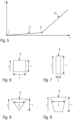
- Fig. 5 shows a diagram to further illustrate the invention.
- Fig. 4 is shown on the horizontal axis the opening movement or the opening stroke
- the at least one flow channel 26, which interrupts the sealing surface 23 of the valve body 22 attached to the valve tappet 15 at at least one circumferential position, can have any cross-sectional area, Fig. 6 to 9 show possible cross-sectional areas for the at least one flow channel 26.
- the cross-sectional areas for the at least one flow channel 26 are each contoured rectangular. Seen along the opening movement Fig. 5 shown linear curve section 27 results. The slope of the curve section 27 is flatter, the greater the length L of the cross-sectional area of the at least one flow channel 26, as seen in the opening movement of the valve tappet 15, in relation to its width B.
- the cross-sectional area of the at least one flow channel 26 is contoured in such a way that the width B of the respective flow channel 26 increases along the opening movement X of the valve tappet 15.
- the cross-sectional contours 8 and 9 for the at least one flow channel 26 are therefore preferred.
- the respective flow channel 26 which interrupts the sealing surface 23 at a respective circumferential position extends in the radial direction and is preferably inclined relative to the axial direction.
- the sealing element 24 it is also possible for the sealing element 24 to rest against a radially outer sealing surface of the valve body 22. In this case, the sealing element 24 does not interact with the radially inner sealing surface 23 but rather with a radially outer sealing surface of the cylindrical or hollow cylindrical or conically contoured valve body 22.
- the invention makes it possible to safely and easily detect a leak that forms downstream of the pressure reducer 10. Even a relatively small leak, which causes a relatively small pressure loss in the back pressure chamber 14 of the pressure reducer 10, causes a movement of the valve tappet 15 of a magnitude that can be detected safely and reliably.
Landscapes
- Physics & Mathematics (AREA)
- General Physics & Mathematics (AREA)
- Fluid Mechanics (AREA)
- Engineering & Computer Science (AREA)
- Automation & Control Theory (AREA)
- Safety Valves (AREA)
- Details Of Valves (AREA)
- Lift Valve (AREA)
Description
- Die vorliegende Beschreibung betrifft Druckminderer wie nach dem Oberbegriff des Anspruchs 1.
- Druckminderer finden vorzugsweise in Industrieanlagen und Wasserversorgungsanlagen von Häusern oder Gebäuden Anwendung, um bei einem schwankenden Eingangsdruck einen konstanten Ausgangsdruck zur Verfügung zu stellen. Die Installation eines Druckminderers erfolgt hierbei vorzugsweise in einem Keller eines Gebäudes oder in einem Versorgungsschacht, sodass die Gefahr des Einfrierens des Druckminderers nicht besteht. Die Notwendigkeit, einen konstanten Fluiddruck oder Wasserdruck zur Verfügung zu stellen, besteht aber nicht nur bei Industrieanlagen und Wasserversorgungsanlagen, vielmehr gibt es auch andere Anwendungsgebiete die mit einem konstanten Fluiddruck oder Wasserdruck versorgt werden müssen. Im Freien installierte Druckminderer sind bei Frost außer Betrieb gesetzt, wozu eine Entleerung derselben erfolgt.
- Ein Druckminderer ist aus der
DE 195 39 239 C2 bekannt. So umfasst der aus diesem Stand der Technik bekannte Druckminderer ein Gehäuse und ein in dem Gehäuse positioniertes Ventil, wobei das Ventil in geschlossenem Zustand desselben einen Vordruckraum des Gehäuses von einem Hinterdruckraum des Gehäuses trennt und in geöffnetem Zustand desselben den Vordruckraum und den Hinterdruckraum verbindet. Das Ventil des aus diesem Stand der Technik bekannten Druckminderers verfügt über eine auf einen Ventilstößel einwirkende Membran, auf die unter Bereitstellung einer Druckminderer-Funktion einerseits eine in Öffnungsrichtung des Ventils wirkende Federkraft eines Federelements und andererseits eine in Schließrichtung des Ventils wirkende, vom im Hinterdruckraum herrschenden Druck abhängige Kraft einwirkt. - Nach der
DE 195 39 239 C2 ist am Ventilstößel ein Ventilkörper befestigt, der mit einem Dichtelement derart zusammenwirkt, dass in geschlossenem Zustand des Ventils der Ventilkörper und das Dichtelement dichtend aneinander anliegen, und dass in geöffnetem Zustand des Ventils der Ventilkörper vom Dichtelement entfernt ist und einen Strömungsbereich zwischen dem Ventilkörper und dem Dichtelement freigibt. -
DE 10 2018 205 016 A1 offenbart einen Druckminderer nach dem Oberbegriff des Anspruch 1. -
DE 10 2016 122 661 A1 offenbart ein Druckreduzierventil. -
DE 10 2013 216 673 A1 offenbart ein Speicherkammerventil. -
US 8 607 818 B2 offenbart ein Druckentlastungsventil. -
EP 1 857 905 A1 offenbart eine Gas-Reguliervorrichtung und einen Gas-Durchflussmesser mit einem Druckreduzierer. - Insbesondere bei einem in einem Gebäude oder einem Haus installierten Druckminderer können dann, wenn in der Wasserversorgungsanlage stromabwärts des Druckminderers eine Leckagestelle vorliegt, durch die Leckage erhebliche Schäden verursacht werden. Bislang bereitet es Schwierigkeiten, eine derartige Leckage, die sich stromabwärts eines Druckminderers ausbilden kann, sicher zu detektieren.
- Aus der
EP 3 239 682 A1 ist eine Vorrichtung zur Detektion von Leckage in einer Wasserversorgungsanlage bekannt. In diesem Stand der Technik wird vorgeschlagen, an der Leckagedetektionsvorrichtung die Bewegung eines Stößels mithilfe eines Sensors zu detektieren und abhängig von der Bewegung des Stößels auf das Vorliegen einer Leckage zu schließen. - Bei einem Druckminderer besteht das Problem, dass kleine Leckagen nur kleine Bewegungen des Ventilstößels verursachen, die nur schwer oder nur mit großem Aufwand detektierbar sind.
- Der Erfindung liegt die Aufgabe zu Grunde, einen neuartigen Druckminderer zu schaffen, bei welchem durch eine Leckage verursachte Bewegungen des Ventilstößels leichter oder mit geringerem Aufwand detektierbar sind.
- Diese Aufgabe wird durch einen Druckminderer gemäß Anspruch 1 gelöst.
- Erfindungsgemäß ist die Dichtfläche in Radialrichtung wirksam und der an dem Ventilstößel befestigte Ventilkörper ist unter Ausbildung der in Radialrichtung wirksamen Dichtfläche zylindrisch oder hohlzylindrisch oder konisch konturiert.
- Die Dichtfläche des an dem Ventilstößel befestigten Ventilkörpers ist erfindungsgemäß an mindestens einer Umfangsposition über mindestens einen Strömungskanal derart unterbrochen, dass abhängig von einem im Hinterdruckraum herrschenden Druckverlust, nämlich abhängig von einer durch eine Fluidleckage oder durch einen regulären Fluidverbrauch verursachten Druckänderung im Hinterdruckraum, entweder das Dichtelement an der Dichtfläche anliegt bzw. in Radialrichtung gesehen gegen die Dichtfläche drückt und einen Strömungsbereich zwischen dem Dichtelement und der Dichtfläche einschließlich des jeweiligen Strömungskanals bzw. des mindestens einen Strömungskanals vollständig verschließt, nämlich dann, weder eine Fluidleckage noch ein regulärer Fluidverbrauch vorliegt und daher die Druckänderung im Hinterdruckraum kleiner als ein unterer Grenzwert ist, oder das Dichtelement von der Dichtfläche entfernt ist und den Strömungsbereich einschließlich des jeweiligen Strömungskanals bzw. des mindestens einen Strömungskanals vollständig freigibt, nämlich dann, wenn ein regulärer Fluidverbrauch vorliegt und daher die Druckänderung im Hinterdruckraum größer als ein oberer Grenzwert ist, oder das Dichtelement an der Dichtfläche anliegt bzw. in Radialrichtung gesehen gegen die Dichtfläche drückt und den Strömungsbereich ausschließlich über den jeweiligen Strömungskanal bzw. den mindestens einen Strömungskanal teilweise freigibt, nämlich dann, wenn kein regulärer Fluidverbrauch sondern lediglich eine Fluidleckage vorliegt und daher die Druckänderung im Hinterdruckraum größer als der untere Grenzwert und kleiner als der obere Grenzwert ist.
- Die Erfindung verfügt über den Vorteil, dass dann, wenn eine Leckage eine relativ geringe Druckänderung im Hinterdruckraum verursacht, der Ventilstößel des Ventils des Druckminderers sich in größerem Umfang bewegt als bei aus dem Stand der Technik bekannten Druckminderern, sodass eine durch eine Leckage verursachte Bewegung des Ventilstößels leichter oder mit geringerem Aufwand detektiert werden kann.
- Dann, wenn im Hinterdruckraum kein Druckverlust oder ein Druckverlust herrscht, der kleiner als ein unterer Grenzwert ist, liegt das Dichtelement an der Dichtfläche an und verschließt den Strömungsbereich zwischen dem Dichtelement und der Dichtfläche einschließlich des jeweiligen Strömungskanals bzw. des mindestens einen Strömungskanals vollständig.
- Dann, wenn im Hinterdruckraum ein Druckverlust herrscht, der größer als ein oberer Grenzwert ist, ist das Dichtelement von der Dichtfläche entfernt und gibt den Strömungsbereich zwischen dem Dichtelement und der Dichtfläche einschließlich des jeweiligen Strömungskanals bzw. des mindestens einen Strömungskanals vollständig frei.
- Dann, wenn im Hinterdruckraum ein Druckverlust herrscht, der größer als der untere Grenzwert und kleiner als der obere Grenzwert ist, liegt das Dichtelement an der Dichtfläche an und gibt den Strömungsbereich zwischen dem Dichtelement und der Dichtfläche ausschließlich über den jeweiligen Strömungs-kanal teilweise frei.
- Nach einer vorteilhaften Weiterbildung der Erfindung drückt das Dichtelement radial innen gegen eine radial innenliegende Dichtfläche des Ventilkörpers. Diese Ausführung ist besonders bevorzugt, um die Erfindung konstruktiv einfach umzusetzen.
- Nach einer vorteilhaften Weiterbildung der Erfindung erstreckt sich der jeweilige Strömungskanal bzw. der mindestens eine Strömungskanal, der die Dichtfläche an einer jeweiligen Umfangsposition unterbricht, in Radialrichtung. Auch dies dient der einfachen konstruktiven Umsetzung der Erfindung.
- Bevorzugte Weiterbildungen der Erfindung ergeben sich aus den Unteransprüchen und der nachfolgenden Beschreibung. Nachfolgend wird ein Ausführungsbeispiel der Erfindung, ohne hierauf beschränkt zu sein, anhand der Zeichnung näher erläutert. In der Zeichnung zeigt:
- Fig. 1
- einen Querschnitt durch einen erfindungsgemäßen Druckminderer;
- Fig. 2
- das Detail Z der
Fig. 1 in einem ersten Zustand; - Fig. 3
- das Detail Z der
Fig. 1 in einem zweiten Zustand; - Fig. 4
- das Detail Z der
Fig. 1 in einem dritten Zustand; - Fig. 5
- ein Diagramm zur Verdeutlichung der Erfindung;
- Fig. 6
- eine erste mögliche Querschnittkonturierung eines Strömungskanals des Druckminderers;
- Fig. 7
- eine zweite mögliche Querschnittkonturierung eines Strömungskanals des Druckminderers;
- Fig. 8
- eine dritte mögliche Querschnittkonturierung eines Strömungskanals des Druckminderers; und
- Fig. 9
- eine vierte mögliche Querschnittkonturierung eines Strömungskanals des Druckminderers.
-
Fig. 1 zeigt einen Querschnitt durch ein Ausführungsbeispiel eines erfindungsgemäßen Druckminderers 10. Der Druckminderer 10 verfügt über ein Gehäuse 11, wobei im Gehäuse 11 ein Ventil 12 positioniert ist. Das Ventil 12 trennt im geschlossenen Zustand einen Vordruckraum 13 des Gehäuses 11 von einem Hinterdruckraum 14 des Gehäuses 11, wobei im geöffneten Zustand des Ventils 12 der Vordruckraum 13 und der Hinterdruckraum 14 gekoppelt sind. - Das Ventil 12 des Druckminderers 10 verfügt über einen Ventilstößel 15, an welchem eine Membran 16 angreift. Auf die Membran 16 wirkt eine Federkraft ein, die von einem Federelement 17 bereitgestellt wird, wobei das Federelement 17 gemäß
Fig. 1 zwischen zwei Federtellern 18, 19 angeordnet ist. Ein erster Federteller 18 ist der Membran 16 zugewandt. Ein zweiter Federteller 19 ist von der Membran 16 abgewandt. Der erste Federteller 18 und die Membran 16 sind aneinander befestigt. - Auf die Membran 16 wirkt zusätzlich zu der Federkraft des Federelements 17, die in Öffnungsrichtung des Ventils 12 wirkt, eine Kraft ein, die in Schließrichtung des Ventils 12 des Druckminderers 10 wirkt, wobei diese Kraft abhängig von einem Druck ist, der in einem von der Membran 16 begrenzten Druckraum 20 herrscht.
- Dieser im Druckraum 20 herrschende Druck bzw. die von diesem Druck abhängige und in Schließrichtung des Ventils 12 des Druckminderers 10 wirkende Kraft ist von dem im Hinterdruckraum 14 herrschenden Druck abhängig. Druckraum 20 und Hinterdruckraum 14 sind über eine Druckleitung 21 gekoppelt.
- An dem Ventilstößel 15 greift nicht nur die Membran 16 an, sondern vielmehr auch ein Ventilkörper 22. Der Ventilkörper 22 weist eine Dichtfläche 23 auf, die mit einem Dichtelement 24 zusammenwirkt.
- Die Dichtfläche 23 des am Ventilstößel 15 befestigten Ventilkörpers 22 wirkt derart mit dem Dichtelement 24 zusammen, dass im geschlossenen Zustand des Ventils 12 das Dichtelement 24 an der Dichtfläche 23 dichtend anliegt und in Radialrichtung gegen die Dichtfläche 23 drückt.
- In geöffnetem Zustand des Ventils 12 hingegen ist das Dichtelement 24 von der Dichtfläche 23 entfernt und liegt nicht an derselben an, wobei in geöffnetem Zustand des Ventils 12 ein Strömungsbereich 25 zwischen dem Dichtelement 24 und der Dichtfläche 23 des Ventilkörpers 22 freigegeben ist.
- Im Sinne der hier vorliegenden Erfindung ist der an dem Ventilstößel 15 befestigte Ventilkörper 22 unter Ausbildung einer sich in Radialrichtung wirksamen Dichtfläche 23 zylindrisch oder hohlzylindrisch oder konisch konturiert.
- Im gezeigten Ausführungsbeispiel ist der Ventilkörper 22 hohlzylindrisch konturiert.
- Die in Radialrichtung wirksame Dichtfläche 23 desselben ist radial innen am Ventilkörper 22 ausgebildet, sodass dann bei geschlossenem Ventil 12 das Dichtelement 24 radial innen gegen die radial innenliegende Dichtfläche 23 des Ventilkörpers 22 drückt.
- Die Dichtfläche 23 des am Ventilstößel 15 befestigten Ventilkörpers 22 ist an mindestens einer Umfangsposition des Ventilkörpers 22 über einen Strömungskanal 26 unterbrochen, derart, dass abhängig von einem im Hinterdruckraum 14 herrschenden Druckverlust entweder das Dichtelement 24 an der Dichtfläche anliegt und in Radialrichtung gesehen gegen die Dichtfläche 23 drückt und den Strömungsbereich 25 zwischen dem Dichtelement 24 und der Dichtfläche 23 einschließlich des jeweiligen Strömungskanals 26 vollständig verschließt, oder das Dichtelement 24 von der Dichtfläche 23 entfernt ist und den Strömungsbereich 25 einschließlich des jeweiligen Strömungskanals 26 vollständig freigibt, oder das Dichtelement 24 an der Dichtfläche anliegt und in Radialrichtung gesehen gegen die Dichtfläche 23 drückt und den Strömungsbereich 25 ausschließlich über den jeweiligen Strömungskanal 26 teilweise freigibt.
- Dann, wenn im Hinterdruckraum 14 kein Druckverlust oder ein Druckverlust herrscht, der kleiner als ein unterer Grenzwert ist, liegt das Dichtelement 24 an der Dichtfläche 23 vollumfänglich an und verschließt den Strömungsbereich 25 zwischen dem Dichtelement 24 und der Dichtfläche 23 einschließlich des jeweiligen Strömungskanals 26 vollständig. Dies ist in
Fig. 2 gezeigt. - Dann hingegen, wenn wie in
Fig. 4 gezeigt, im Hinterdruckraum 14 ein Druckverlust herrscht, der größer als ein oberer Grenzwert ist, ist das Dichtelement 24 von der Dichtfläche 23 des Ventilkörpers 22 entfernt bzw. abgehoben und gibt den Strömungsbereich 25 zwischen dem Dichtelement 24 und der Dichtfläche 23 einschließlich des jeweiligen Strömungskanals 26 vollständig frei. - Dann, wenn im Hinterdruckraum 14 ein Druckverlust herrscht, der größer als der untere Grenzwert und kleiner als der obere Grenzwert ist, liegt das Dichtelement 24 an der Dichtfläche 23 an, gibt jedoch den Strömungsbereich zwischen dem Dichtelement 24 und der Dichtfläche 23 teilweise frei, nämlich ausschließlich über den jeweiligen Strömungskanal 26, welcher die Dichtfläche 23 an mindestens einer Umfangsposition unterbricht. Dies ist in
Fig. 3 gezeigt. - Das Ventil 12 des Druckminderers 10 nimmt den Zustand der
Fig. 2 dann ein, wenn im Hinterdruckraum 14 kein Druckverlust herrscht, wenn also weder ein regulärer Fluidverbrauch oder Wasserverbrauch vorliegt noch eine Fluidleckage oder Wasserleckage stromabwärts des Hinterdruckraums 14. - Dann, wenn ein regulärer Fluidverbrauch oder Wasserverbrauch vorliegt, nimmt das Ventil 12 des Druckminderers 10 den Zustand der
Fig. 4 ein, durch eine Relativbewegung des am Ventilstößel 15 befestigten Ventilkörpers 22 relativ zum Dichtelement 24 ist das Dichtelement 24 von der Dichtfläche 23 entfernt und gibt so Strömungsbereich 25 vollständig frei. - Liegt hingegen kein regulärer Fluidverbrauch oder Wasserverbrauch vor, sondern lediglich eine Leckage oder eine sehr geringe Entnahme an Fluid oder Wasser stromabwärts des Hinterdruckraums 14, so nimmt das Ventil 12 des erfindungsgemäßen Druckminderers 10 den Zustand der
Fig. 3 ein. In diesem Fall liegt das Dichtelement 24 noch an der Dichtfläche 23 des Ventilkörpers 22 an, durch eine Relativbewegung zwischen dem Ventilkörper 22 und dem Dichtelement 24 gibt das Dichtelement 24 jedoch mindestens einen Strömungskanal 26 frei, welcher an einer jeweiligen Umfangsposition die Dichtfläche 23 unterbricht. Sollte demnach eine Leckage auftreten, so kann über den Strömungskanal 26 eine Strömung erfolgen, wodurch im Vergleich zu aus dem Stand der Technik bekannten Druckminderern eine relativ große Bewegung des Ventilstößels 15 verursacht wird, die mithilfe eines dem Ventilstößel 15 zugeordneten, nicht gezeigten Sensors erfasst und detektiert werden kann. - Es sei angemerkt, dass bei einer Leckage im Gegensatz zu einem regulären Fluidverbrauch oder Wasserverbrauch eine leckagebedingte Fluidentnahme oder Wasserentnahme ungewollt kontinuierlich erfolgt, da über eine Leckagestelle dauerhaft Fluid oder Wasser entweicht. Der Ventilkörper 22 des Druckminderers 10 regelt sich leckageabhängig auf eine entsprechende Position ein, welche den leckabedingten Druckverlust im Hinterdruckraum 14 ausgleicht und eine definierte Bewegung bzw. einen definierten Hub des Ventilstößels 15 verursacht, die bzw. der mithilfe des dem Ventilstößel 15 zugeordneten, nicht gezeigten Sensors erfasst und detektiert werden kann.
-
Fig. 5 zeigt ein Diagramm zur weiteren Verdeutlichung der Erfindung. InFig. 4 ist auf der horizontalen Achse die Öffnungsbewegung bzw. der Öffnungshub X des Ventilstößels 15 und auf der vertikalen Achse Y eine Fluidentnahme oder Wasserentnahme aus dem Hinterdruckraum 14 gezeigt. - Dann, wenn weder ein regulärer Fluidverbrauch oder Wasserverbrauch noch eine Fluidleckage oder Wasserleckage stromabwärts des Hinterdruckraums 14 vorliegt, wenn also das Ventil 12 des Druckminderers 10 den Zustand der
Fig. 2 einnimmt, liegt im Diagramm derFig. 5 der Zustand I vor. - Dann, wenn kein regulärer Fluidverbrauch oder Wasserverbrauch vorliegt, sondern lediglich eine Leckage und wenn das Ventil 12 des erfindungsgemäßen Druckminderers 10 den Zustand der
Fig. 3 einnimmt, folgt die Öffnungsbewegung bzw. der Öffnungshub X des Ventilstößels 15 dem Kurvenabschnitt 27 derFig. 5 . Eine relativ kleine Fluidentnahme oder Wasserentnahme bedingt dann einen relativ große Öffnungsbewegung X des Ventilstößels 15. Dies folgt aus der Steigung des Kurvenabschnitts 27. Diese kann mithilfe des dem Ventilstößel 15 zugeordneten, nicht gezeigten Sensors erfasst und detektiert werden. - Dann, wenn ein regulärer Fluidverbrauch oder Wasserverbrauch vorliegt, wenn also das Ventil 12 des Druckminderers 10 den Zustand der
Fig. 4 einnimmt, folgt die Öffnungsbewegung bzw. der Öffnungshub X des Ventilstößels 15 dem Kurvenabschnitt 28 derFig. 5 . Eine relative große Fluidentnahme oder Wasserentnahme bedingt eine relativ kleine Öffnungsbewegung X des Ventilstößels 15. Dies folgt aus der Steigung des Kurvenabschnitts 28. - Im Zustand II der
Fig. 5 , in welchem der Kurvenabschnitts 27 in den Kurvenabschnitt 28 übergeht, beginnt das Dichtelement 24 sich von Dichtfläche 23 zu entfernen und beginnt den Strömungsbereich 25 vollständig freizugeben. - Der mindestens eine Strömungskanal 26, welcher die Dichtfläche 23 des an dem Ventilstößel 15 befestigten Ventilkörpers 22 an mindestens einer Umfangsposition unterbricht, kann eine beliebige Querschnittsfläche aufweisen,
Fig. 6 bis 9 zeigen mögliche Querschnittsflächen für den mindestens einen Strömungskanal 26. - In
Fig. 6 und 7 sind die Querschnittsflächen für den mindestens einen Strömungskanal 26 jeweils rechteckig konturiert. Entlang der Öffnungsbewegung X des Ventilstößels 15 und damit des Ventilkörpers 22 gesehen ist eine Breite B des jeweiligen Strömungskanals 26 über seine Länge L konstant, sodass sich dann der inFig. 5 gezeigte lineare Kurvenabschnitt 27 ergibt. Die Steigung des Kurvenabschnitts 27 ist dabei umso flacher, je größer die in der Öffnungsbewegung des Ventilstößels 15 gesehen die Länge L der Querschnittsfläche des mindestens einen Strömungskanals 26 im Verhältnis zu seiner Breite B ist. - In
Fig. 8 und 9 sind Querschnittsflächen für den mindestens einen Strömungskanal 26 gezeigt, bei welchen entlang der Öffnungsbewegung X des Ventilstößels 15 gesehen eine Breite B des jeweiligen Strömungskanals 26 über seine Länge L zunimmt. Der Kurvenabschnitt 27 würde dann einen parabelartigen Verlauf aufweisen. - Um einen Druckverlust über den Ventilkörper 22 bei Erreichen des Zustands II der
Fig. 5 zu optimieren, ist es von Vorteil, wenn die Querschnittsfläche des mindestens einen Strömungskanal 26 so konturiert ist, dass entlang der Öffnungsbewegung X des Ventilstößels 15 gesehen die Breite B des jeweiligen Strömungskanals 26 zunimmt. Die Querschnittskonturierungen nachFig. 8 und 9 für den mindestens einen Strömungskanals 26 sind demnach bevorzugt. - Wie
Fig. 2, 3 und 4 entnommen werden kann, erstreckt sich der jeweilige die Dichtfläche 23 an einer jeweiligen Umfangsposition unterbrechende Strömungskanal 26 in Radialrichtung und ist vorzugsweise gegenüber der Axialrichtung schräg gestellt. - Im Unterschied zum gezeigten Ausführungsbeispiel ist es auch möglich, dass das Dichtelement 24 an einer radial äußeren Dichtfläche des Ventilkörpers 22 anliegt. In diesem Fall wirkt dann das Dichtelement 24 nicht mit der radial inneren Dichtfläche 23 sondern vielmehr mit einer radial äußeren Dichtfläche des zylindrisch oder hohlzylindrisch oder konisch konturierten Ventilkörpers 22 zusammen.
- Die Erfindung ermöglicht es, eine Leckage, die sich stromabwärts des Druckminderers 10 ausbildet, sicher und einfach zu detektieren. Selbst eine relativ geringe Leckage, die im Hinterdruckraum 14 des Druckminderers 10 einen relativ geringen Druckverlust verursacht, bewirkt eine Bewegung des Ventilstößels 15 in einer Größenordnung, die sicher und zuverlässig detektiert werden kann.
-
- 10
- Druckminderer
- 11
- Gehäuse
- 12
- Ventil
- 13
- Vordruckraum
- 14
- Hinterdruckraum
- 15
- Ventilstößel
- 16
- Membran
- 17
- Federelement
- 18
- Federteller
- 19
- Federteller
- 20
- Druckraum
- 21
- Druckleitung
- 22
- Ventilkörper
- 23
- Dichtfläche
- 24
- Dichtelement
- 25
- Strömungsbereich
- 26
- Strömungskanal
- 27
- Kurvenabschnitt
- 28
- Kurvenabschnitt
Claims (5)
- Druckminderer (10),mit einem Gehäuse (11), das einen Vordruckraum (13) und einen Hinterdruckraum (14) definiert,mit einem in dem Gehäuse (11) positionierten Ventil (12),wobei das Ventil (12) in geschlossenem Zustand den Vordruckraum (13) des Gehäuses (11) von dem Hinterdruckraum (14) des Gehäuses (11) trennt und in geöffnetem Zustand den Vordruckraum (13) und den Hinterdruckraum (14) verbindet,wobei das Ventil (12) eine auf einen Ventilstößel (15) einwirkende Membran (16) aufweist, auf die unter Bereitstellung einer Druckminderer-Funktion einerseits eine in Öffnungsrichtung des Ventils (12) wirkende Federkraft eines Federelements (17) und andererseits eine in Schließrichtung des Ventils (12) wirkende, von einem im Hinterdruckraum (14) herrschenden Druck abhängige Kraft einwirkt,wobei das Ventil (12) einen an dem Ventilstößel (15) befestigten Ventilkörper (22) mit einer Dichtfläche (23) aufweist, die mit einem Dichtelement (24) derart zusammenwirkt, dass im geschlossenen Zustand des Ventils (12) das Dichtelement (24) an der Dichtfläche (23) dichtend anliegt und gegen die Dichtfläche (23) drückt, und dass in geöffnetem Zustand des Ventils (12) das Dichtelement (24) von der Dichtfläche (23) entfernt ist und nicht an derselben anliegt, wobei in geöffnetem Zustand des Ventils (12) ein Strömungsbereich (25) zwischen dem Dichtelement (24) und der Dichtfläche (23) des Ventilkörpers (22) freigegeben ist,dadurch gekennzeichnet, dassdie Dichtfläche (23) in Radialrichtung wirksam ist und der an dem Ventilstößel (15) befestigte Ventilkörper (22) unter Ausbildung der in Radialrichtung wirksamen Dichtfläche (23) zylindrisch oder hohlzylindrisch oder konisch konturiert ist, unddie Dichtfläche (23) des an dem Ventilstößel (15) befestigten Ventilkörpers (22) an mindestens einer Umfangsposition über mindestens einen Strömungskanal (26) derart unterbrochen ist, dass abhängig von einem im Hinterdruckraum (14) herrschenden Druckverlust, nämlich abhängig von einer durch eine Fluidleckage oder durch einen regulären Fluidverbrauch verursachten Druckänderung im Hinterdruckraum (14),entweder das Dichtelement (24) an der Dichtfläche (23) anliegt und den Strömungsbereich (25) zwischen dem Dichtelement (24) und der Dichtfläche (23) einschließlich des jeweiligen Strömungskanals (26) vollständig verschließt, nämlich dann, wenn weder eine Fluidleckage noch ein regulärer Fluidverbrauch vorliegt und daher die Druckänderung im Hinterdruckraum (14) kleiner als ein unterer Grenzwert ist,oder das Dichtelement (24) von der Dichtfläche (23) entfernt ist und den Strömungsbereich (25) zwischen dem Dichtelement (24) und der Dichtfläche (23) einschließlich des jeweiligen Strömungskanals (26) vollständig freigibt, nämlich dann, wenn ein regulärer Fluidverbrauch vorliegt und daher die Druckänderung im Hinterdruckraum (14) größer als ein oberer Grenzwert ist,oder das Dichtelement (24) an der Dichtfläche (23) anliegt und den Strömungsbereich (25) zwischen dem Dichtelement (24) und der Dichtfläche (23) ausschließlich über den jeweiligen Strömungskanal (26) teilweise freigibt, nämlich dann, wenn kein regulärer Fluidverbrauch sondern lediglich eine Fluidleckage vorliegt und daher die Druckänderung im Hinterdruckraum (14) größer als der untere Grenzwert und kleiner als der obere Grenzwert ist.
- Druckminderer nach Anspruch 1, dadurch gekennzeichnet, dass das Dichtelement (24) radial innen gegen eine radial innenliegende Dichtfläche (23) des Ventilkörpers (22) drückt.
- Druckminderer nach Anspruch 1, dadurch gekennzeichnet, dass das Dichtelement (24) radial außen gegen eine radial außenliegende Dichtfläche des Ventilkörpers (22) drückt.
- Druckminderer nach einem der Ansprüche 1 bis 3, dadurch gekennzeichnet, dass sich der mindestens eine Strömungskanal (26), der die Dichtfläche (23) an einer jeweiligen Umfangsposition unterbricht, in Radialrichtung erstreckt.
- Druckminderer nach einem der Ansprüche 1 bis 4, dadurch gekennzeichnet, dass dem Ventilstößel (15) ein Sensor zugeordnet ist, welcher die Bewegung des Ventilstößels (15) erfasst.
Applications Claiming Priority (2)
| Application Number | Priority Date | Filing Date | Title |
|---|---|---|---|
| DE102020107027.6A DE102020107027A1 (de) | 2020-03-13 | 2020-03-13 | Druckminderer |
| PCT/EP2021/056079 WO2021180802A1 (de) | 2020-03-13 | 2021-03-10 | Druckminderer |
Publications (2)
| Publication Number | Publication Date |
|---|---|
| EP4118510A1 EP4118510A1 (de) | 2023-01-18 |
| EP4118510B1 true EP4118510B1 (de) | 2024-01-31 |
Family
ID=74873748
Family Applications (1)
| Application Number | Title | Priority Date | Filing Date |
|---|---|---|---|
| EP21711838.9A Active EP4118510B1 (de) | 2020-03-13 | 2021-03-10 | Druckminderer |
Country Status (5)
| Country | Link |
|---|---|
| US (2) | US12093062B2 (de) |
| EP (1) | EP4118510B1 (de) |
| CN (1) | CN115210672B (de) |
| DE (1) | DE102020107027A1 (de) |
| WO (1) | WO2021180802A1 (de) |
Families Citing this family (2)
| Publication number | Priority date | Publication date | Assignee | Title |
|---|---|---|---|---|
| DE102020107027A1 (de) * | 2020-03-13 | 2021-09-16 | Pittway Sarl | Druckminderer |
| CN121957178A (zh) * | 2020-08-07 | 2026-05-01 | 固瑞克明尼苏达有限公司 | 背压调节器 |
Family Cites Families (25)
| Publication number | Priority date | Publication date | Assignee | Title |
|---|---|---|---|---|
| US3902522A (en) * | 1973-01-16 | 1975-09-02 | Braukmann Armaturen | Pressure reducer |
| DE19539239C2 (de) | 1995-10-21 | 1998-05-28 | Honeywell Ag | Druckminderer |
| US6637452B1 (en) * | 2002-10-08 | 2003-10-28 | Fisher Controls International, Inc. | Valve with self-cleaning trim |
| DE102006016318B4 (de) * | 2006-04-06 | 2008-06-05 | Knorr-Bremse Systeme für Schienenfahrzeuge GmbH | Schraubenverdichter mit Entlastungsventil |
| EP1857905B1 (de) | 2006-05-16 | 2012-06-27 | Mesura | Reguliervorrichtung und Durchflussmesser für Gas mit Druckreduzierer und Ventilklappe zum Verschluss des Durchflusswegs des Gases |
| DE102007026162A1 (de) | 2006-11-15 | 2008-05-29 | Hans Sasserath & Co. Kg | Absperrvorrichtung |
| ITMO20080043A1 (it) * | 2008-02-19 | 2009-08-20 | P A S R L | Valvola di by-pass e di regolazione pressione perfezionata. |
| DK177066B1 (da) * | 2008-05-05 | 2011-05-23 | Frese As | Reguleringsventil |
| DE102009025441A1 (de) * | 2009-06-16 | 2011-01-05 | Honeywell Technologies Sarl | Ventil für Flüssigkeiten mit einem Drehknopf mit Vordrehsicherung |
| US8607818B2 (en) | 2010-05-20 | 2013-12-17 | Dresser, Inc. | Pressure relief valve |
| KR101928855B1 (ko) * | 2011-03-14 | 2018-12-13 | 라발 에이.씨.에스. 엘티디 | 연료 밸브 |
| DE202011051425U1 (de) * | 2011-09-23 | 2013-01-08 | Hans Sasserath & Co. Kg | Druckminderer-Anordnung |
| CN105473915A (zh) * | 2013-03-11 | 2016-04-06 | 滨特尔民用水处理有限责任公司 | 机械压力开关 |
| DE102013216673A1 (de) | 2013-08-22 | 2015-02-26 | Robert Bosch Gmbh | Speicherkammerventil |
| US10663987B2 (en) * | 2015-02-20 | 2020-05-26 | The West Group Limited | Pressure regulator |
| DE102015118962A1 (de) * | 2015-11-05 | 2017-05-11 | Knorr-Bremse Systeme für Nutzfahrzeuge GmbH | Druckbegrenzungsventil |
| EP3239682B1 (de) | 2016-04-27 | 2020-08-12 | Honeywell Technologies Sarl | Leckdetektionsvorrichtung und wassersystem mit einer leckdetektionsvorrichtung |
| DE102016122661A1 (de) | 2016-11-24 | 2018-05-24 | Frank Plastic Ag | Druckreduzierventil für flüssige und gasförmige Medien |
| IT201700099507A1 (it) * | 2017-09-05 | 2019-03-05 | Fimcim Spa | Valvola di controllo di pressione differenziale |
| US10551855B2 (en) * | 2017-09-29 | 2020-02-04 | Emerson Process Management Regulator Technologies, Inc. | Regulator with convertible trim assembly |
| SE542140C2 (en) * | 2017-11-08 | 2020-03-03 | Mann Teknik Ab | Improved coupling with pressure relief |
| DE102018205016A1 (de) * | 2018-04-04 | 2019-10-10 | Honeywell Technologies Sarl | Druckminderer |
| DE102019111981A1 (de) * | 2019-05-08 | 2020-11-12 | Pittway Sarl | Druckminderer |
| EP3865969B1 (de) * | 2020-02-12 | 2023-04-05 | Pittway Sarl | Druckreduzierventil und verfahren zu dessen betrieb |
| DE102020107027A1 (de) * | 2020-03-13 | 2021-09-16 | Pittway Sarl | Druckminderer |
-
2020
- 2020-03-13 DE DE102020107027.6A patent/DE102020107027A1/de active Pending
-
2021
- 2021-03-10 CN CN202180020722.1A patent/CN115210672B/zh active Active
- 2021-03-10 EP EP21711838.9A patent/EP4118510B1/de active Active
- 2021-03-10 WO PCT/EP2021/056079 patent/WO2021180802A1/de not_active Ceased
- 2021-03-10 US US17/906,154 patent/US12093062B2/en active Active
-
2024
- 2024-09-16 US US18/886,170 patent/US20250093891A1/en active Pending
Also Published As
| Publication number | Publication date |
|---|---|
| US20230176596A1 (en) | 2023-06-08 |
| WO2021180802A1 (de) | 2021-09-16 |
| US20250093891A1 (en) | 2025-03-20 |
| CN115210672A (zh) | 2022-10-18 |
| DE102020107027A1 (de) | 2021-09-16 |
| US12093062B2 (en) | 2024-09-17 |
| CN115210672B (zh) | 2025-06-03 |
| EP4118510A1 (de) | 2023-01-18 |
Similar Documents
| Publication | Publication Date | Title |
|---|---|---|
| DE19509126C2 (de) | Rückschlagventil | |
| EP2420708B1 (de) | Schaltventil | |
| DE20009605U1 (de) | Vorrichtung zur Entölung von Kurbelgehäuse-Entlüftungsgasen einer Brennkraftmaschine | |
| DE2204219A1 (de) | Durchflußregelsystem | |
| EP1741843B1 (de) | Systemtrenner | |
| EP4118510A1 (de) | Druckminderer | |
| EP3736654B1 (de) | Druckminderer | |
| EP2523063B2 (de) | Druckminderer | |
| DE2413273C3 (de) | Druckminderventil | |
| DE3323324C3 (de) | Verfahren und Vorrichtung zum Steuern eines Rohrtrenners in Abhängigkeit einer an einer Vergleichsstelle vorgegebenen Druckdifferenz | |
| DE102009001099A1 (de) | Kraftstoffeinspritzventil | |
| DD287761A5 (de) | Thermisch gesteuertes ventil | |
| DE4328299C2 (de) | Zwischen einer Saug- und einer Druckleitung eines hydraulischen Drucksystems mit insbesondere großer Förderleistung angeordnetes Absperrventil für unter hohem Druck stehende Flüssigkeit | |
| DE102015218905A1 (de) | Abblaseventil | |
| EP4187133A1 (de) | Ventil | |
| DE10236783B4 (de) | Druckregelventil | |
| DE3002361C2 (de) | ||
| DE3347805C2 (de) | Vorrichtung zum Anpassen des Ansprechdruckes an die in der Abflußleitung gegebenen Druckverhältnisse bei einer Einrichtung zum Verhindern des Rückflusses eines Mediums aus einer Abflußleitung zurück in die Zuflußleitung | |
| DE2759703C2 (de) | ||
| DE20108618U1 (de) | Ventil, insbesondere Absteuer- oder Umgehungsventil für ein fluides Medium | |
| DE102007039025A1 (de) | Vorrichtung zum Sperren des Durchflusses von fluiden Medien in Rohrleitungen, Schläuchen oder dergleichen, insbesondere Rückschlagventil | |
| EP1918538B1 (de) | Ventil zur Regelung von Drücken | |
| EP1895188B1 (de) | Verstellbares Dämpfventil | |
| DE9319172U1 (de) | Rückschlagventil | |
| DE3901809C2 (de) | Entlüftungsventil |
Legal Events
| Date | Code | Title | Description |
|---|---|---|---|
| STAA | Information on the status of an ep patent application or granted ep patent |
Free format text: STATUS: UNKNOWN |
|
| STAA | Information on the status of an ep patent application or granted ep patent |
Free format text: STATUS: THE INTERNATIONAL PUBLICATION HAS BEEN MADE |
|
| PUAI | Public reference made under article 153(3) epc to a published international application that has entered the european phase |
Free format text: ORIGINAL CODE: 0009012 |
|
| STAA | Information on the status of an ep patent application or granted ep patent |
Free format text: STATUS: REQUEST FOR EXAMINATION WAS MADE |
|
| 17P | Request for examination filed |
Effective date: 20221006 |
|
| AK | Designated contracting states |
Kind code of ref document: A1 Designated state(s): AL AT BE BG CH CY CZ DE DK EE ES FI FR GB GR HR HU IE IS IT LI LT LU LV MC MK MT NL NO PL PT RO RS SE SI SK SM TR |
|
| DAV | Request for validation of the european patent (deleted) | ||
| DAX | Request for extension of the european patent (deleted) | ||
| GRAP | Despatch of communication of intention to grant a patent |
Free format text: ORIGINAL CODE: EPIDOSNIGR1 |
|
| STAA | Information on the status of an ep patent application or granted ep patent |
Free format text: STATUS: GRANT OF PATENT IS INTENDED |
|
| RIC1 | Information provided on ipc code assigned before grant |
Ipc: G01M 3/28 20060101ALI20230728BHEP Ipc: G05D 16/06 20060101AFI20230728BHEP |
|
| INTG | Intention to grant announced |
Effective date: 20230816 |
|
| P01 | Opt-out of the competence of the unified patent court (upc) registered |
Effective date: 20230827 |
|
| GRAS | Grant fee paid |
Free format text: ORIGINAL CODE: EPIDOSNIGR3 |
|
| GRAA | (expected) grant |
Free format text: ORIGINAL CODE: 0009210 |
|
| STAA | Information on the status of an ep patent application or granted ep patent |
Free format text: STATUS: THE PATENT HAS BEEN GRANTED |
|
| AK | Designated contracting states |
Kind code of ref document: B1 Designated state(s): AL AT BE BG CH CY CZ DE DK EE ES FI FR GB GR HR HU IE IS IT LI LT LU LV MC MK MT NL NO PL PT RO RS SE SI SK SM TR |
|
| REG | Reference to a national code |
Ref country code: GB Ref legal event code: FG4D Free format text: NOT ENGLISH Ref country code: CH Ref legal event code: EP |
|
| REG | Reference to a national code |
Ref country code: DE Ref legal event code: R096 Ref document number: 502021002594 Country of ref document: DE |
|
| REG | Reference to a national code |
Ref country code: IE Ref legal event code: FG4D Free format text: LANGUAGE OF EP DOCUMENT: GERMAN |
|
| REG | Reference to a national code |
Ref country code: LT Ref legal event code: MG9D |
|
| REG | Reference to a national code |
Ref country code: NL Ref legal event code: MP Effective date: 20240131 |
|
| PG25 | Lapsed in a contracting state [announced via postgrant information from national office to epo] |
Ref country code: IS Free format text: LAPSE BECAUSE OF FAILURE TO SUBMIT A TRANSLATION OF THE DESCRIPTION OR TO PAY THE FEE WITHIN THE PRESCRIBED TIME-LIMIT Effective date: 20240531 |
|
| PG25 | Lapsed in a contracting state [announced via postgrant information from national office to epo] |
Ref country code: LT Free format text: LAPSE BECAUSE OF FAILURE TO SUBMIT A TRANSLATION OF THE DESCRIPTION OR TO PAY THE FEE WITHIN THE PRESCRIBED TIME-LIMIT Effective date: 20240131 |
|
| PG25 | Lapsed in a contracting state [announced via postgrant information from national office to epo] |
Ref country code: GR Free format text: LAPSE BECAUSE OF FAILURE TO SUBMIT A TRANSLATION OF THE DESCRIPTION OR TO PAY THE FEE WITHIN THE PRESCRIBED TIME-LIMIT Effective date: 20240501 |
|
| PG25 | Lapsed in a contracting state [announced via postgrant information from national office to epo] |
Ref country code: HR Free format text: LAPSE BECAUSE OF FAILURE TO SUBMIT A TRANSLATION OF THE DESCRIPTION OR TO PAY THE FEE WITHIN THE PRESCRIBED TIME-LIMIT Effective date: 20240131 Ref country code: RS Free format text: LAPSE BECAUSE OF FAILURE TO SUBMIT A TRANSLATION OF THE DESCRIPTION OR TO PAY THE FEE WITHIN THE PRESCRIBED TIME-LIMIT Effective date: 20240430 Ref country code: NL Free format text: LAPSE BECAUSE OF FAILURE TO SUBMIT A TRANSLATION OF THE DESCRIPTION OR TO PAY THE FEE WITHIN THE PRESCRIBED TIME-LIMIT Effective date: 20240131 |
|
| PG25 | Lapsed in a contracting state [announced via postgrant information from national office to epo] |
Ref country code: ES Free format text: LAPSE BECAUSE OF FAILURE TO SUBMIT A TRANSLATION OF THE DESCRIPTION OR TO PAY THE FEE WITHIN THE PRESCRIBED TIME-LIMIT Effective date: 20240131 |
|
| PG25 | Lapsed in a contracting state [announced via postgrant information from national office to epo] |
Ref country code: RS Free format text: LAPSE BECAUSE OF FAILURE TO SUBMIT A TRANSLATION OF THE DESCRIPTION OR TO PAY THE FEE WITHIN THE PRESCRIBED TIME-LIMIT Effective date: 20240430 Ref country code: NO Free format text: LAPSE BECAUSE OF FAILURE TO SUBMIT A TRANSLATION OF THE DESCRIPTION OR TO PAY THE FEE WITHIN THE PRESCRIBED TIME-LIMIT Effective date: 20240430 Ref country code: NL Free format text: LAPSE BECAUSE OF FAILURE TO SUBMIT A TRANSLATION OF THE DESCRIPTION OR TO PAY THE FEE WITHIN THE PRESCRIBED TIME-LIMIT Effective date: 20240131 Ref country code: LT Free format text: LAPSE BECAUSE OF FAILURE TO SUBMIT A TRANSLATION OF THE DESCRIPTION OR TO PAY THE FEE WITHIN THE PRESCRIBED TIME-LIMIT Effective date: 20240131 Ref country code: IS Free format text: LAPSE BECAUSE OF FAILURE TO SUBMIT A TRANSLATION OF THE DESCRIPTION OR TO PAY THE FEE WITHIN THE PRESCRIBED TIME-LIMIT Effective date: 20240531 Ref country code: HR Free format text: LAPSE BECAUSE OF FAILURE TO SUBMIT A TRANSLATION OF THE DESCRIPTION OR TO PAY THE FEE WITHIN THE PRESCRIBED TIME-LIMIT Effective date: 20240131 Ref country code: GR Free format text: LAPSE BECAUSE OF FAILURE TO SUBMIT A TRANSLATION OF THE DESCRIPTION OR TO PAY THE FEE WITHIN THE PRESCRIBED TIME-LIMIT Effective date: 20240501 Ref country code: FI Free format text: LAPSE BECAUSE OF FAILURE TO SUBMIT A TRANSLATION OF THE DESCRIPTION OR TO PAY THE FEE WITHIN THE PRESCRIBED TIME-LIMIT Effective date: 20240131 Ref country code: ES Free format text: LAPSE BECAUSE OF FAILURE TO SUBMIT A TRANSLATION OF THE DESCRIPTION OR TO PAY THE FEE WITHIN THE PRESCRIBED TIME-LIMIT Effective date: 20240131 Ref country code: BG Free format text: LAPSE BECAUSE OF FAILURE TO SUBMIT A TRANSLATION OF THE DESCRIPTION OR TO PAY THE FEE WITHIN THE PRESCRIBED TIME-LIMIT Effective date: 20240131 |
|
| PG25 | Lapsed in a contracting state [announced via postgrant information from national office to epo] |
Ref country code: PT Free format text: LAPSE BECAUSE OF FAILURE TO SUBMIT A TRANSLATION OF THE DESCRIPTION OR TO PAY THE FEE WITHIN THE PRESCRIBED TIME-LIMIT Effective date: 20240531 Ref country code: PL Free format text: LAPSE BECAUSE OF FAILURE TO SUBMIT A TRANSLATION OF THE DESCRIPTION OR TO PAY THE FEE WITHIN THE PRESCRIBED TIME-LIMIT Effective date: 20240131 |
|
| PG25 | Lapsed in a contracting state [announced via postgrant information from national office to epo] |
Ref country code: SE Free format text: LAPSE BECAUSE OF FAILURE TO SUBMIT A TRANSLATION OF THE DESCRIPTION OR TO PAY THE FEE WITHIN THE PRESCRIBED TIME-LIMIT Effective date: 20240131 Ref country code: PT Free format text: LAPSE BECAUSE OF FAILURE TO SUBMIT A TRANSLATION OF THE DESCRIPTION OR TO PAY THE FEE WITHIN THE PRESCRIBED TIME-LIMIT Effective date: 20240531 Ref country code: PL Free format text: LAPSE BECAUSE OF FAILURE TO SUBMIT A TRANSLATION OF THE DESCRIPTION OR TO PAY THE FEE WITHIN THE PRESCRIBED TIME-LIMIT Effective date: 20240131 Ref country code: LV Free format text: LAPSE BECAUSE OF FAILURE TO SUBMIT A TRANSLATION OF THE DESCRIPTION OR TO PAY THE FEE WITHIN THE PRESCRIBED TIME-LIMIT Effective date: 20240131 |
|
| PG25 | Lapsed in a contracting state [announced via postgrant information from national office to epo] |
Ref country code: DK Free format text: LAPSE BECAUSE OF FAILURE TO SUBMIT A TRANSLATION OF THE DESCRIPTION OR TO PAY THE FEE WITHIN THE PRESCRIBED TIME-LIMIT Effective date: 20240131 |
|
| PG25 | Lapsed in a contracting state [announced via postgrant information from national office to epo] |
Ref country code: SM Free format text: LAPSE BECAUSE OF FAILURE TO SUBMIT A TRANSLATION OF THE DESCRIPTION OR TO PAY THE FEE WITHIN THE PRESCRIBED TIME-LIMIT Effective date: 20240131 |
|
| PG25 | Lapsed in a contracting state [announced via postgrant information from national office to epo] |
Ref country code: EE Free format text: LAPSE BECAUSE OF FAILURE TO SUBMIT A TRANSLATION OF THE DESCRIPTION OR TO PAY THE FEE WITHIN THE PRESCRIBED TIME-LIMIT Effective date: 20240131 Ref country code: CZ Free format text: LAPSE BECAUSE OF FAILURE TO SUBMIT A TRANSLATION OF THE DESCRIPTION OR TO PAY THE FEE WITHIN THE PRESCRIBED TIME-LIMIT Effective date: 20240131 |
|
| PG25 | Lapsed in a contracting state [announced via postgrant information from national office to epo] |
Ref country code: SK Free format text: LAPSE BECAUSE OF FAILURE TO SUBMIT A TRANSLATION OF THE DESCRIPTION OR TO PAY THE FEE WITHIN THE PRESCRIBED TIME-LIMIT Effective date: 20240131 |
|
| PG25 | Lapsed in a contracting state [announced via postgrant information from national office to epo] |
Ref country code: SM Free format text: LAPSE BECAUSE OF FAILURE TO SUBMIT A TRANSLATION OF THE DESCRIPTION OR TO PAY THE FEE WITHIN THE PRESCRIBED TIME-LIMIT Effective date: 20240131 Ref country code: SK Free format text: LAPSE BECAUSE OF FAILURE TO SUBMIT A TRANSLATION OF THE DESCRIPTION OR TO PAY THE FEE WITHIN THE PRESCRIBED TIME-LIMIT Effective date: 20240131 Ref country code: RO Free format text: LAPSE BECAUSE OF FAILURE TO SUBMIT A TRANSLATION OF THE DESCRIPTION OR TO PAY THE FEE WITHIN THE PRESCRIBED TIME-LIMIT Effective date: 20240131 Ref country code: EE Free format text: LAPSE BECAUSE OF FAILURE TO SUBMIT A TRANSLATION OF THE DESCRIPTION OR TO PAY THE FEE WITHIN THE PRESCRIBED TIME-LIMIT Effective date: 20240131 Ref country code: DK Free format text: LAPSE BECAUSE OF FAILURE TO SUBMIT A TRANSLATION OF THE DESCRIPTION OR TO PAY THE FEE WITHIN THE PRESCRIBED TIME-LIMIT Effective date: 20240131 Ref country code: CZ Free format text: LAPSE BECAUSE OF FAILURE TO SUBMIT A TRANSLATION OF THE DESCRIPTION OR TO PAY THE FEE WITHIN THE PRESCRIBED TIME-LIMIT Effective date: 20240131 |
|
| REG | Reference to a national code |
Ref country code: CH Ref legal event code: PL |
|
| REG | Reference to a national code |
Ref country code: DE Ref legal event code: R097 Ref document number: 502021002594 Country of ref document: DE |
|
| PG25 | Lapsed in a contracting state [announced via postgrant information from national office to epo] |
Ref country code: LU Free format text: LAPSE BECAUSE OF NON-PAYMENT OF DUE FEES Effective date: 20240310 |
|
| PG25 | Lapsed in a contracting state [announced via postgrant information from national office to epo] |
Ref country code: MC Free format text: LAPSE BECAUSE OF FAILURE TO SUBMIT A TRANSLATION OF THE DESCRIPTION OR TO PAY THE FEE WITHIN THE PRESCRIBED TIME-LIMIT Effective date: 20240131 |
|
| PG25 | Lapsed in a contracting state [announced via postgrant information from national office to epo] |
Ref country code: MC Free format text: LAPSE BECAUSE OF FAILURE TO SUBMIT A TRANSLATION OF THE DESCRIPTION OR TO PAY THE FEE WITHIN THE PRESCRIBED TIME-LIMIT Effective date: 20240131 Ref country code: LU Free format text: LAPSE BECAUSE OF NON-PAYMENT OF DUE FEES Effective date: 20240310 |
|
| PG25 | Lapsed in a contracting state [announced via postgrant information from national office to epo] |
Ref country code: IT Free format text: LAPSE BECAUSE OF FAILURE TO SUBMIT A TRANSLATION OF THE DESCRIPTION OR TO PAY THE FEE WITHIN THE PRESCRIBED TIME-LIMIT Effective date: 20240131 |
|
| PLBE | No opposition filed within time limit |
Free format text: ORIGINAL CODE: 0009261 |
|
| STAA | Information on the status of an ep patent application or granted ep patent |
Free format text: STATUS: NO OPPOSITION FILED WITHIN TIME LIMIT |
|
| REG | Reference to a national code |
Ref country code: BE Ref legal event code: MM Effective date: 20240331 |
|
| PG25 | Lapsed in a contracting state [announced via postgrant information from national office to epo] |
Ref country code: IT Free format text: LAPSE BECAUSE OF FAILURE TO SUBMIT A TRANSLATION OF THE DESCRIPTION OR TO PAY THE FEE WITHIN THE PRESCRIBED TIME-LIMIT Effective date: 20240131 |
|
| 26N | No opposition filed |
Effective date: 20241101 |
|
| PG25 | Lapsed in a contracting state [announced via postgrant information from national office to epo] |
Ref country code: BE Free format text: LAPSE BECAUSE OF NON-PAYMENT OF DUE FEES Effective date: 20240331 |
|
| PG25 | Lapsed in a contracting state [announced via postgrant information from national office to epo] |
Ref country code: FR Free format text: LAPSE BECAUSE OF NON-PAYMENT OF DUE FEES Effective date: 20240331 |
|
| PG25 | Lapsed in a contracting state [announced via postgrant information from national office to epo] |
Ref country code: IE Free format text: LAPSE BECAUSE OF NON-PAYMENT OF DUE FEES Effective date: 20240310 |
|
| PG25 | Lapsed in a contracting state [announced via postgrant information from national office to epo] |
Ref country code: IE Free format text: LAPSE BECAUSE OF NON-PAYMENT OF DUE FEES Effective date: 20240310 Ref country code: FR Free format text: LAPSE BECAUSE OF NON-PAYMENT OF DUE FEES Effective date: 20240331 Ref country code: BE Free format text: LAPSE BECAUSE OF NON-PAYMENT OF DUE FEES Effective date: 20240331 Ref country code: CH Free format text: LAPSE BECAUSE OF NON-PAYMENT OF DUE FEES Effective date: 20240331 |
|
| PG25 | Lapsed in a contracting state [announced via postgrant information from national office to epo] |
Ref country code: SI Free format text: LAPSE BECAUSE OF FAILURE TO SUBMIT A TRANSLATION OF THE DESCRIPTION OR TO PAY THE FEE WITHIN THE PRESCRIBED TIME-LIMIT Effective date: 20240131 |
|
| PGFP | Annual fee paid to national office [announced via postgrant information from national office to epo] |
Ref country code: AT Payment date: 20250417 Year of fee payment: 5 |
|
| PGFP | Annual fee paid to national office [announced via postgrant information from national office to epo] |
Ref country code: DE Payment date: 20250428 Year of fee payment: 5 |
|
| PG25 | Lapsed in a contracting state [announced via postgrant information from national office to epo] |
Ref country code: CY Free format text: LAPSE BECAUSE OF FAILURE TO SUBMIT A TRANSLATION OF THE DESCRIPTION OR TO PAY THE FEE WITHIN THE PRESCRIBED TIME-LIMIT; INVALID AB INITIO Effective date: 20210310 |
|
| PG25 | Lapsed in a contracting state [announced via postgrant information from national office to epo] |
Ref country code: HU Free format text: LAPSE BECAUSE OF FAILURE TO SUBMIT A TRANSLATION OF THE DESCRIPTION OR TO PAY THE FEE WITHIN THE PRESCRIBED TIME-LIMIT; INVALID AB INITIO Effective date: 20210310 |
|
| PG25 | Lapsed in a contracting state [announced via postgrant information from national office to epo] |
Ref country code: TR Free format text: LAPSE BECAUSE OF FAILURE TO SUBMIT A TRANSLATION OF THE DESCRIPTION OR TO PAY THE FEE WITHIN THE PRESCRIBED TIME-LIMIT Effective date: 20240131 |
|
| PGFP | Annual fee paid to national office [announced via postgrant information from national office to epo] |
Ref country code: GB Payment date: 20260323 Year of fee payment: 6 |