EP4114617B1 - Werkzeugmaschine mit einer energieversorgungseinrichtung - Google Patents
Werkzeugmaschine mit einer energieversorgungseinrichtung Download PDFInfo
- Publication number
- EP4114617B1 EP4114617B1 EP21706000.3A EP21706000A EP4114617B1 EP 4114617 B1 EP4114617 B1 EP 4114617B1 EP 21706000 A EP21706000 A EP 21706000A EP 4114617 B1 EP4114617 B1 EP 4114617B1
- Authority
- EP
- European Patent Office
- Prior art keywords
- supply device
- energy supply
- machine tool
- tool housing
- interface
- Prior art date
- Legal status (The legal status is an assumption and is not a legal conclusion. Google has not performed a legal analysis and makes no representation as to the accuracy of the status listed.)
- Active
Links
Images



Classifications
-
- B—PERFORMING OPERATIONS; TRANSPORTING
- B25—HAND TOOLS; PORTABLE POWER-DRIVEN TOOLS; MANIPULATORS
- B25F—COMBINATION OR MULTI-PURPOSE TOOLS NOT OTHERWISE PROVIDED FOR; DETAILS OR COMPONENTS OF PORTABLE POWER-DRIVEN TOOLS NOT PARTICULARLY RELATED TO THE OPERATIONS PERFORMED AND NOT OTHERWISE PROVIDED FOR
- B25F5/00—Details or components of portable power-driven tools not particularly related to the operations performed and not otherwise provided for
- B25F5/02—Construction of casings, bodies or handles
-
- B—PERFORMING OPERATIONS; TRANSPORTING
- B25—HAND TOOLS; PORTABLE POWER-DRIVEN TOOLS; MANIPULATORS
- B25D—PERCUSSIVE TOOLS
- B25D11/00—Portable percussive tools with electromotor or other motor drive
-
- B—PERFORMING OPERATIONS; TRANSPORTING
- B25—HAND TOOLS; PORTABLE POWER-DRIVEN TOOLS; MANIPULATORS
- B25D—PERCUSSIVE TOOLS
- B25D11/00—Portable percussive tools with electromotor or other motor drive
- B25D11/06—Means for driving the impulse member
- B25D11/12—Means for driving the impulse member comprising a crank mechanism
-
- B—PERFORMING OPERATIONS; TRANSPORTING
- B25—HAND TOOLS; PORTABLE POWER-DRIVEN TOOLS; MANIPULATORS
- B25D—PERCUSSIVE TOOLS
- B25D17/00—Details of, or accessories for, portable power-driven percussive tools
-
- B—PERFORMING OPERATIONS; TRANSPORTING
- B25—HAND TOOLS; PORTABLE POWER-DRIVEN TOOLS; MANIPULATORS
- B25D—PERCUSSIVE TOOLS
- B25D17/00—Details of, or accessories for, portable power-driven percussive tools
- B25D17/20—Devices for cleaning or cooling tool or work
-
- B—PERFORMING OPERATIONS; TRANSPORTING
- B25—HAND TOOLS; PORTABLE POWER-DRIVEN TOOLS; MANIPULATORS
- B25F—COMBINATION OR MULTI-PURPOSE TOOLS NOT OTHERWISE PROVIDED FOR; DETAILS OR COMPONENTS OF PORTABLE POWER-DRIVEN TOOLS NOT PARTICULARLY RELATED TO THE OPERATIONS PERFORMED AND NOT OTHERWISE PROVIDED FOR
- B25F5/00—Details or components of portable power-driven tools not particularly related to the operations performed and not otherwise provided for
- B25F5/008—Cooling means
-
- B—PERFORMING OPERATIONS; TRANSPORTING
- B25—HAND TOOLS; PORTABLE POWER-DRIVEN TOOLS; MANIPULATORS
- B25D—PERCUSSIVE TOOLS
- B25D2250/00—General details of portable percussive tools; Components used in portable percussive tools
- B25D2250/121—Housing details
Definitions
- the present invention relates to a machine tool, in particular a chisel hammer, comprising a drive, a percussion mechanism device, a control device, a power supply device for supplying the machine tool with electrical energy and a machine tool housing with a first and a second machine tool housing region.
- Machine tools configured as drilling and/or chisel hammers of the type mentioned above are generally known from the prior art.
- a machine tool according to the preamble of claim 1 is already known from US 2013/255980 A1 known.
- Handling or operating large, hand-held machine tools can be difficult in certain situations because they are often heavy and have an even mass or weight distribution. Even a slight change in the position of the machine tool can therefore lead to almost uncontrollable destabilization and sudden deflection. As a result, it is also possible for the machine tool to be dropped by a user and cause it to crash to the ground. Damage to the machine tool, and in particular to the components of the machine tool's power supply, is therefore possible. Damage to the power supply can occur especially because the components of the power supply are often located in exposed parts of the machine tool.
- a machine tool in particular a chisel hammer, comprising a drive, a percussion device, a control device, a power supply device for supplying the machine tool with electrical energy and a machine tool housing with a first and a second machine tool housing area.
- the energy supply device is positionable in one direction between the first and second machine tool housing area, wherein a first interface for connecting the energy supply device to the first machine tool housing area and a second interface for connecting the energy supply device to the second machine tool housing area.
- Both the first and the second interface are designed to establish a removable mechanical connection with the respective first and second machine tool housing areas.
- the mechanical connection can be designed in the form of a positive and/or non-positive coupling. It is possible for the mechanical connection to be designed in the form of a tongue and groove system or in the form of a rail system.
- the first and second interfaces are designed to establish a removable electrical connection with the respective first and second machine tool housing areas. With the aid of the electrical connection, electrical energy can be conducted from the energy supply device to the first and/or second machine tool housing areas.
- the first and second interfaces and the energy supply device can be designed such that electrical communication signals can be transported from the first or second machine tool housing area via the energy supply device to the second or first machine tool housing area.
- the machine tool is designed such that the first and second interfaces are configured to releasably connect the energy supply device to the first and second machine tool housing areas.
- the energy supply device is designed as a battery connection device with at least one battery interface for releasably connecting the energy supply device to at least one battery.
- the energy supply device may be designed as a mains connection device with a line for releasably connecting the machine tool to a mains power source.
- the energy supply device may contain at least one ventilation duct, wherein the at least one ventilation duct extends substantially from a top side to a bottom side of the energy supply device.
- the at least one ventilation duct may contain at least one fan for generating an air flow through the at least one ventilation duct.
- the machine tool may be designed such that a center of gravity of the power supply device and a center of gravity of the tool housing lie substantially at an intersection point of a first and second plane, wherein the first and second planes are arranged perpendicular to one another. This provides a nearly optimal balance and weight distribution, and improves the handling of the machine tool.
- Figure 1 and 2 shows a machine tool 1 in the form of a chisel hammer.
- the machine tool 1 can also be a hammer drill, combination hammer, or the like.
- the machine tool 1 it is also possible for the machine tool 1 to be designed in the form of a saw, a grinder, a drill, a hammer drill, a screwdriver, or another hand-held power tool.
- the machine tool 1 essentially contains a machine tool housing 2, a first handle device 3a and a second handle device 3b, a tool holder device 4, a drive 5, a striking mechanism 6, a control device and a power supply device 7, cf. Figures 2 to 4 .
- the energy supply device 7 serves to supply the electrical consumers with electrical energy.
- the drive 5 is designed as an electric motor and serves to drive the impact mechanism 6.
- the impact mechanism 6 serves to generate impacts or impact pulses.
- the drive 5 and the impact mechanism 6 are connected to each other.
- the impact mechanism 6, in turn, is connected to the tool holder 4 in such a way that the impact pulses generated by the impact mechanism 6 are transmitted to the tool holder 4.
- control device is not shown in the figures.
- the machine tool housing 2 contains a first machine tool housing area 20 and a second machine tool housing area 30. As in Figure 3 As indicated, the drive 5 and the impact mechanism 6 are positioned in the first machine tool housing area 20. As in particular the Figure 2 As can be seen, a display device 9 and an input device 10 are provided at an upper end of the second machine tool housing area 20.
- the display device 9 serves to display different states of the machine tool 1.
- the input device 10 serves to enter information and to set different states of the machine tool 1.
- the first machine tool housing portion 20 in turn includes a first end 20a and a second end 20b.
- the second machine tool housing portion 30 also includes a first end 30a and a second end 30b.
- the tool holder device 4 is positioned at the first end 20a of the first machine tool housing area 20.
- the tool holder device 4 serves for Picking up and holding a tool.
- the tool is not shown in the figures.
- the first handle device 3a is positioned at the first end 20a of the first machine tool housing region 20.
- a first interface 22 is provided at the second end 20b of the first machine tool housing region 20.
- the first interface 22 serves to detachably connect the first machine tool housing region 20 to the energy supply device 7.
- the first and second ends 20a, 20b of the first machine tool housing region 20 are positioned and aligned essentially one behind the other in direction A.
- a second interface 32 is positioned at the first end 30a of the second machine tool housing portion 30.
- the second interface 32 serves to releasably connect the second machine tool housing portion 30 to the power supply device 7.
- the second handle device 3b is positioned at the second end 30b of the second machine tool housing portion 30.
- the first and second ends 30a, 30b of the second machine tool housing portion 30 are positioned and aligned substantially one behind the other in direction A.
- Both the first and the second handle devices 3a, 3b serve to hold and guide the machine tool 1. It is provided that one hand of a user of the machine tool 1 holds the machine tool 1 on the first handle device 3a and another hand on the second handle device 3b. The user is not shown in the figures.
- the second handle device 3b contains an actuating switch 12 for actuating or activating the machine tool 1.
- the actuating switch 12 is connected to the control device, the energy supply device 7 and the drive 5.
- the energy supply device 7 contains a first interface 7a and a second interface 7b. With the aid of the first interface 7a of the energy supply device 7, the energy supply device 7 can be releasably connected to the first interface 22 of the first machine tool housing area 20. With the aid of the second interface 7b of the energy supply device 7, the energy supply device 7 can be releasably connected to the second interface 32 of the second machine tool housing area 30.
- the energy supply device 7 is shown in a first embodiment.
- the energy supply device 7 is designed in the form of a battery connection device with a battery interface 13 for releasably connecting the energy supply device 7 to a battery 14.
- the energy supply device 7 contains for this purpose a base body 15 in the form of a shaft-shaped hollow cylinder.
- the base body 15 essentially contains a first, second, third and fourth side wall 15a, 15b, 15c, 15d.
- the first and second side walls 15a, 15b as well as the third and fourth side walls 15c, 15d are opposite one another, so that a continuous shaft 16 in the form of a central continuous recess with a receiving volume AV is created in the base body 15.
- a fan 17 is positioned in the shaft 16 of the base body 15.
- the fan 17 serves to generate an air flow LS through the shaft 16 of the base body 15 in order to cool the shaft 16.
- Each of the four side walls 15a, 15b, 15c, 15d has an inner side 18 and an outer side 19.
- the first interface 7a is positioned on the outer side 19 of the first side wall 15a.
- the second interface 7b is positioned on the outer wall 19 of the second side wall 15b. Both the first and the second interface 7a, 7b are designed to establish a detachable mechanical connection with the respective first and second machine tool housing areas 20, 30.
- the mechanical connection can be designed in the form of a positive and/or non-positive coupling.
- the electrical contact elements are not shown in the figures.
- both the first and second interfaces 7a, 7b of the energy supply device 7 as well as the first interface 22 of the first machine tool housing area 20 and the second interface 32 of the second machine tool housing area 30 each contain communication elements to transport communication signals from the first or second machine tool housing area 20, 30 via the energy supply device 7 to the second or first machine tool housing area 20, 30. Communication signals can also be transmitted from the energy supply device 7 to the first and/or second Machine tool housing area 20, 30 are sent and/or received.
- the communication elements are not shown in the figures.
- the battery interface 13 is positioned on the inner side 18 of the first side wall 15a of the energy supply device 7.
- the fan 17 is arranged in direction C below the battery interface 13, see. Figure 5 .
- an air flow LS generated by the fan 17 can cool a rechargeable battery 14 connected to the rechargeable battery interface 13.
- a rechargeable battery 14 can be detachably connected to the energy supply device 7 such that the electrical energy stored in the rechargeable battery 14 can be transported from the rechargeable battery 14 to the energy supply device 7.
- the rechargeable battery interface 13 is designed such that the rechargeable battery 14 can be pushed in the direction C onto the rechargeable battery interface 13 to create a detachable connection.
- the rechargeable battery interface 13 and an upper side of the rechargeable battery 14 have a tongue and groove system. The tongue and groove system is not shown in the figures.
- the power supply device 7 is configured as a mains connection device.
- the power supply device 7 configured as a mains connection device contains a control unit, a transformer, and a line 40 for releasably connecting the machine tool 1 to a mains power source.
- Electrical energy can be supplied to the power supply device 7 via the line 40. As already described above, the electrical energy can then be transported from the power supply device 7 to the first and/or second machine tool housing area 20, 30 via the first and second interfaces 7a, 7b.
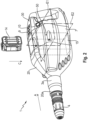
- the energy supply device 7 contains a ventilation duct 25 which extends from a first opening 26 on a bottom side 8a to a second opening 28 on a top side 8b over the entire length of the energy supply device 7.
- the fan 17 is positioned in the ventilation duct 25 such that an air flow LS can flow through the ventilation duct 25 in order to cool the energy supply device 7.
- the energy supply device 7 serves to connect the two machine tool housing areas 20, 30 with each other. If, as in Figure 6 As can be seen, the energy supply device 7 is removed, the first and second machine tool housing areas 20, 30 are separated from each other.
- the machine tool 1 and in particular the two machine tool housing areas 20, 30 and the energy supply device 7 are designed such that a center of gravity of the energy supply device 7 and a center of gravity of the tool housing 1 lie essentially on a single intersection point 50 of a first and second plane E1, E2, wherein the first and second planes E1, E2 are arranged perpendicular to one another.
Landscapes
- Engineering & Computer Science (AREA)
- Mechanical Engineering (AREA)
- Percussive Tools And Related Accessories (AREA)
Description
- Die vorliegende Erfindung betrifft eine Werkzeugmaschine, insbesondere Meißelhammer, enthaltend einen Antrieb, eine Schlagwerkvorrichtung, eine Steuerungsvorrichtung, eine Energieversorgungsvorrichtung zur Versorgung der Werkzeugmaschine mit elektrischer Energie sowie ein Werkzeugmaschinengehäuse mit einem ersten und zweiten Werkzeugmaschinengehäusebereich.
- Werkzeugmaschinen in Ausgestaltung als Bohr- und/oder Meisselhammer der eingangs genannten Art sind aus dem Stand der Technik grundsätzlich bekannt. Eine Werkzeugmaschine gemäß dem Oberbegriff des Anspruchs 1 ist bereits aus der
US 2013/255980 A1 bekannt. - Die Handhabung bzw. das Bedienen handgeführter großer Werkzeugmaschinen kann sich in gewissen Situationen als schwierig gestalten, da diese Werkzeugmaschinen oftmals schwer und eine ausgeglichene Massen- bzw. Gewichtsverteilung aufweisen. Auch eine geringfügige Lageveränderung der Werkzeugmaschine kann daher zu einer fast unkontrollierbaren Destabilisierung und plötzlichen Ablenken führen. Als Folge daraus ist es auch möglich, dass die Werkzeugmaschine von einem Anwender fallengelassen wird und auf den Boden stürzt. Beschädigungen an der Werkzeugmaschine und insbesondere an den Komponenten einer Energieversorgung der Werkzeugmaschine sind dementsprechend möglich. Schäden an der Energieversorgung können speziell deshalb geschehen, da die Komponenten der Energieversorgung häufig an exponierten Stellen der Werkzeugmaschine befinden.
- Es ist Aufgabe der vorliegenden Erfindung einen Werkzeugmaschine bereitzustellen, die eine verbesserte Handhabung bzw. Bedienung ermöglicht sowie einen besseren Schutz für die Energieversorgung der Werkzeugmaschine gewährleistet.
- Die Aufgabe wird gelöst durch eine Werkzeugmaschine, insbesondere Meißelhammer, enthaltend einen Antrieb, eine Schlagwerkvorrichtung, eine Steuerungsvorrichtung, eine Energieversorgungsvorrichtung zur Versorgung der Werkzeugmaschine mit elektrischer Energie sowie ein Werkzeugmaschinengehäuse mit einem ersten und zweiten Werkzeugmaschinengehäusebereich.
- Erfindungsgemäß ist vorgesehen, dass die Energieversorgungsvorrichtung in einer Richtung zwischen dem ersten und zweiten Werkzeugmaschinengehäusebereich positionierbar ist, wobei eine erste Schnittstelle zur Verbindung der Energieversorgungsvorrichtung mit dem ersten Werkzeugmaschinengehäusebereich sowie eine zweite Schnittstelle zur Verbindung der Energieversorgungsvorrichtung mit dem zweiten Werkzeugmaschinengehäusebereich vorgesehen ist.
- Sowohl die erste als auch die zweite Schnittstelle ist dabei ausgestaltet, um eine wiederlösbare mechanische Verbindung mit dem jeweils ersten und zweiten Werkzeugmaschinengehäusebereich einzugehen. Die mechanische Verbindung kann dabei in Form einer formschlüssigen und/oder kraftschlüssigen Kopplung gestaltet sein. Es ist dabei möglich, dass die mechanische Verbindung in Form eines Nut-und-Feder-Systems oder in Form eines Schienensystems ausgestaltet ist. Darüber hinaus ist die erste und zweite Schnittstelle ausgestaltet, um eine wiederlösbare elektrische Verbindung mit dem jeweils ersten und zweiten Werkzeugmaschinengehäusebereich einzugehen. Mit Hilfe der elektrischen Verbindung kann elektrische Energie von der Energieversorgungsvorrichtung zu dem ersten und/oder zweiten Werkzeugmaschinengehäusebereich geleitet werden. Des Weiteren kann die ersten und zweite Schnittstelle sowie die Energieversorgungsvorrichtung so ausgestaltet sein, dass elektrische Kommunikationssignale von dem ersten oder zweiten Werkzeugmaschinengehäusebereich über die Energieversorgungsvorrichtung zu dem zweiten oder ersten Werkzeugmaschinengehäusebereich transportiert werden können.
- Die Werkzeugmaschine ist dabei so ausgeführt, dass die erste und zweite Schnittstelle ausgestaltet sind, um die Energieversorgungsvorrichtung wiederlösbar mit dem ersten und zweiten Werkzeugmaschinengehäusebereich zu verbinden.
- Erfindungsgemäß ist die Energieversorgungsvorrichtung als Akkuanschlusseinrichtung mit wenigstens einer Akkuschnittstelle zum wiederlösbaren Verbinden der Energieversorgungsvorrichtung mit wenigstens einem Akkumulator ausgestaltet.
- Gemäß einer nicht erfindungsgemäßen Ausgestaltung kann es möglich sein, dass die Energieversorgungsvorrichtung als Netzanschlusseinrichtung mit einer Leitung zum wiederlösbaren Verbinden der Werkzeugmaschine mit einer Netzstromquelle ausgestaltet ist.
- Entsprechend einer vorteilhaften Ausgestaltung der vorliegenden Erfindung kann es möglich sein, dass die Energieversorgungsvorrichtung wenigstens einen Lüftungskanal enthält, wobei sich der wenigstens eine Lüftungskanal im Wesentlichen von einer Oberseite zu einer Unterseite der Energieversorgungsvorrichtung erstreckt.
- Gemäß einer vorteilhaften Ausgestaltung der vorliegenden Erfindung kann es möglich sein, dass in dem wenigstens einen Lüftungskanal mindestens ein Lüfter zum Erzeugen eines Luftstroms durch den wenigstens einen Lüftungskanal enthalten ist.
- Gemäß einer weiteren vorteilhaften Ausführungsform kann es möglich sein, dass die Werkzeugmaschine so ausgestaltet, dass ein Schwerpunkt der Energieversorgungsvorrichtung sowie ein Schwerpunkt des Werkzeuggehäuses im Wesentlichen auf eine Schnittpunkt von einer ersten und zweiten Ebene liegen, wobei die erste und zweite Ebene senkrecht zueinander angeordnet. Hierdurch ist eine nahezu optimale Balance und Gewichtsverteilung gegeben und das Handling bzw. die Handhabung der Werkzeugmaschine verbessert.
- Weitere Vorteile ergeben sich aus der folgenden Figurenbeschreibung. In den Figuren sind verschiedene Ausführungsbeispiele der vorliegenden Erfindung dargestellt. Die Figuren, die Beschreibung und die Ansprüche enthalten zahlreiche Merkmale in Kombination. Der Fachmann wird die Merkmale zweckmäßigerweise auch einzeln betrachten und zu sinnvollen weiteren Kombinationen zusammenfassen.
- In den Figuren sind gleiche und gleichartige Komponenten mit gleichen Bezugszeichen beziffert. Es zeigen:
- Figur 1
- eine Seitenansicht auf eine Werkzeugmaschine mit einer Energieversorgungsvorrichtung in Form einer Akkuanschlusseinrichtung mit einem innen liegenden Akkumulator zwischen einem ersten und zweiten Werkzeugmaschinengehäusebereich;
- Figur 2
- eine perspektivische Vorderansicht auf die Werkzeugmaschine mit dem Akkumulator außerhalb der in Form einer Akkuanschlusseinrichtung ausgestalteten Energieversorgungsvorrichtung;
- Figur 3
- eine weitere Seitenansicht auf die Werkzeugmaschine mit dem Akkumulator im Inneren der in Form einer Akkuanschlusseinrichtung ausgestalteten Energieversorgungsvorrichtung;
- Figur 4
- eine Seitenansicht auf die in Form einer Akkuanschlusseinrichtung ausgestalteten Energieversorgungsvorrichtung mit einem im Inneren positionierten Akkumulator sowie einem Lüfter in einem Lüftungskanal;
- Figur 5
- eine perspektivische Rückansicht auf die in Form einer Akkuanschlusseinrichtung ausgestalteten Energieversorgungsvorrichtung ohne Akkumulator;
- Figur 6
- eine weitere Seitenansicht auf die Werkzeugmaschine mit dem ersten und zweiten Werkzeugmaschinengehäusebereich ohne eine Energieversorgungsvorrichtung;
- Figur 7
- eine Seitenansicht auf die Werkzeugmaschine mit der Energieversorgungsvorrichtung in Form einer Netzanschlusseinrichtung zwischen dem ersten und zweiten Werkzeugmaschinengehäusebereich;
- Figur 8
- eine weitere Seitenansicht auf die Werkzeugmaschine mit der Energieversorgungsvorrichtung in Form einer Netzanschlusseinrichtung mit einem Lüfter in einem Lüftungskanal; und
- Figur 9
- eine Seitenansicht auf die Energieversorgungsvorrichtung in Form einer Netzanschlusseinrichtung mit dem Lüfter in dem Lüftungskanal.
-
Figur 1 und2 zeigt eine Werkzeugmaschine 1 in Ausgestaltung eines Meißelhammers. Bei der Werkzeugmaschine 1 kann es sich aber auch um einen Bohrhammer, Kombihammer oder dergleichen handeln. Es ist jedoch auch möglich, dass die Werkzeugmaschine 1 in Form einer Säge, eines Schleifgeräts, einer Bohrmaschine, eines Bohrhammers, eines Schraubers oder eines anderen handgeführten Elektrowerkzeuges ausgestaltet ist. - Die Werkzeugmaschine 1 enthält im Wesentlichen ein Werkzeugmaschinengehäuse 2, eine erste Handgriffeinrichtung 3a und zweite Handgriffeinrichtung 3b, eine Werkzeugaufnahmeeinrichtung 4, einen Antrieb 5, ein Schlagwerk 6, eine Steuerungseinrichtung sowie eine Energieversorgungsvorrichtung 7, vgl.
Figur 2 bis 4 . - Die Energieversorgungsvorrichtung 7 dient dabei zur Versorgung der elektrischen Verbraucher mit elektrischer Energie.
- Der Antrieb 5 ist in Form eines Elektromotors ausgestaltet und dient zum Antreiben des Schlagwerks 6. Das Schlagwerk 6 dient zum Erzeugen von Schlägen bzw. Schlagimpulsen. Der Antrieb 5 und das Schlagwerk 6 sind miteinander verbunden. Das Schlagwerk 6 ist wiederum so mit der Werkzeugaufnahmeeinrichtung 4, dass die vom Schlagwerk 6 erzeugten Schlagimpulse auf die Werkzeugaufnahmeeinrichtung 4 weitergegeben werden.
- Die Steuerungseinrichtung ist in den Figuren nicht dargestellt.
- Das Werkzeugmaschinengehäuse 2 enthält dabei einen ersten Werkzeugmaschinengehäusebereich 20 und zweiten Werkzeugmaschinengehäusebereich 30. Wie in
Figur 3 angedeutet, ist in dem ersten Werkzeugmaschinengehäusebereich 20 der Antrieb 5 und das Schlagwerk 6 positioniert. Wie insbesondere derFigur 2 zu entnehmen ist, ist eine Anzeigeeinrichtung 9 sowie eine Eingabeeinrichtung 10 an einem oberen Ende des zweiten Werkzeugmaschinengehäusebereichs 20 vorgesehen. Die Anzeigeeinrichtung 9 dient zum Anzeigen unterschiedlicher Zustände der Werkzeugmaschine 1. Die Eingabeeinrichtung 10 dient zum Eingeben von Informationen und zum Einstellen unterschiedlicher Zustände der Werkzeugmaschine 1. - Der erste Werkzeugmaschinengehäusebereich 20 enthält wiederum ein erstes Ende 20a und ein zweites Ende 20b. Der zweite Werkzeugmaschinengehäusebereich 30 enthält ebenfalls ein erstes Ende 30a und ein zweites Ende 30b.
- An dem ersten Ende 20a des ersten Werkzeugmaschinengehäusebereichs 20 ist die Werkzeugaufnahmeeinrichtung 4 positioniert. Die Werkzeugaufnahmeeinrichtung 4 dient zum Aufnehmen und Halten eines Werkzeuges. Das Werkzeug ist in den Figuren nicht gezeigt. In dem Falle der Ausgestaltung der Werkzeugmaschine 1 in Form eines Meißelhammers ist das Werkzeug als Meißel ausgestaltet. Darüber hinaus ist an dem ersten Ende 20a des ersten Werkzeugmaschinengehäusebereichs 20 die erste Handgriffeinrichtung 3a positioniert. An dem zweiten Ende 20b des ersten Werkzeugmaschinengehäusebereichs 20 ist eine erste Schnittstelle 22 vorgesehen. Die erste Schnittstelle 22 dient zum wiederlösbaren Verbinden des ersten Werkzeugmaschinengehäusebereichs 20 mit der Energieversorgungsvorrichtung 7. Das erste und zweite Ende 20a, 20b des ersten Werkzeugmaschinengehäusebereichs 20 sind in Richtung A im Wesentlichen hintereinander positioniert und ausgerichtet.
- An dem ersten Ende 30a des zweiten Werkzeugmaschinengehäusebereichs 30 ist eine zweite Schnittstelle 32 positioniert. Die zweite Schnittstelle 32 dient zum wiederlösbaren Verbinden des zweiten Werkzeugmaschinengehäusebereichs 30 mit der Energieversorgungsvorrichtung 7. An dem zweiten Ende 30b des zweiten Werkzeugmaschinengehäusebereichs 30 ist die zweite Handgriffeinrichtung 3b positioniert. Das erste und zweite Ende 30a, 30b des zweiten Werkzeugmaschinengehäusebereichs 30 sind in Richtung A im Wesentlichen hintereinander positioniert und ausgerichtet.
- Sowohl die ersten als auch die zweite Handgriffeinrichtung 3a, 3b dient zum Halten und Führen der Werkzeugmaschine 1. Es ist dabei vorgesehen, dass jeweils eine Hand eines Anwenders der Werkzeugmaschine 1 an der ersten Handgriffeinrichtung 3a und eine andere Hand an der zweiten Handgriffeinrichtung 3b die Werkzeugmaschine 1 festhält. Der Anwender ist in den Figuren nicht gezeigt.
- Wie den
Figuren 2 und3 zu entnehmen ist, enthält die zweite Handgriffeinrichtung 3b einen Betätigungsschalter 12 zum Betätigen bzw. Aktivieren der Werkzeugmaschine 1. Der Betätigungsschalter 12 ist mit der Steuerungseinrichtung, der Energieversorgungsvorrichtung 7 und mit dem Antrieb 5 verbunden. - Wie den
Figuren 3 ,4 ,5 ,8 und9 zu nehmen ist, enthält die Energieversorgungsvorrichtung 7 eine erste Schnittstelle 7a sowie eine zweite Schnittstelle 7b. Mit Hilfe der ersten Schnittstelle 7a der Energieversorgungsvorrichtung 7 kann die Energieversorgungsvorrichtung 7 wiederlösbar mit der ersten Schnittstelle 22 des ersten Werkzeugmaschinengehäusebereichs 20 verbunden werden. Mit Hilfe der zweiten Schnittstelle 7b der Energieversorgungsvorrichtung 7 kann die Energieversorgungsvorrichtung 7 wiederlösbar mit der zweiten Schnittstelle 32 des zweiten Werkzeugmaschinengehäusebereichs 30 verbunden werden. - In den
Figuren 1 bis 5 ist die Energieversorgungsvorrichtung 7 in einer ersten Ausführungsform dargestellt. Gemäß einer ersten Ausführungsform ist die Energieversorgungsvorrichtung 7 in Form einer Akkuanschlusseinrichtung mit einer Akkuschnittstelle 13 zum wiederlösbaren Verbinden der Energieversorgungsvorrichtung 7 mit einem Akkumulator 14 ausgestaltet. Die Energieversorgungsvorrichtung 7 enthält hierzu einen Grundkörper 15 in Ausgestaltung eines schachtförmigen Hohlzylinders. Der Grundkörper 15 enthält im Wesentlichen eine erste, zweite, dritte und vierte Seitenwand 15a, 15b, 15c, 15d. Die erste und zweite Seitenwand 15a, 15b sowie die dritte und vierte Seitenwand 15c, 15d liegen sich jeweils gegenüber, sodass ein durchgehender Schacht 16 in Form einer zentralen durchgehenden Ausnehmung mit einem Aufnahmevolumen AV in dem Grundkörper 15 entsteht. Wie in denFiguren 3 bis 5 angedeutet, ist ein Lüfter 17 in dem Schacht 16 des Grundkörpers 15 positioniert. Der Lüfter 17 dient zum Erzeugen eines Luftstroms LS durch den Schacht 16 des Grundkörpers 15, um den Schacht 16 zu kühlen. Jede der vier Seitenwände 15a, 15b, 15c, 15d weist jeweils eine Innenseite 18 und eine Außenseite 19 auf. Wie insbesondere in derFigur 5 dargestellt, ist an der Außenseite 19 der ersten Seitenwand 15a die erste Schnittstelle 7a positioniert. Des Weiteren ist an der Außenwand 19 der zweiten Seitenwand 15b die zweite Schnittstelle 7b positioniert. Sowohl die erste als auch die zweite Schnittstelle 7a, 7b ist ausgestaltet, um eine wiederlösbare mechanische Verbindung mit dem jeweils ersten und zweiten Werkzeugmaschinengehäusebereich 20, 30 einzugehen. Die mechanische Verbindung kann dabei in Form einer formschlüssigen und/oder kraftschlüssigen Kopplung gestaltet sein. - Darüber hinaus enthält sowohl die erste als auch zweite Schnittstelle 7a, 7b der Energieversorgungsvorrichtung 7 sowie die erste Schnittstelle 22 des ersten Werkzeugmaschinengehäusebereichs 20 und die zweite Schnittstelle 32 des zweiten Werkzeugmaschinengehäusebereichs 30 jeweils elektrische Kontaktelemente, sodass elektrische Energie von der Energieversorgungsvorrichtung 7 zu dem ersten und/oder zweiten Werkzeugmaschinengehäusebereich 20, 30 gelangen kann. Die elektrischen Kontaktelemente sind in den Figuren nicht dargestellt.
- Des Weiteren enthält sowohl die erste als auch zweite Schnittstelle 7a, 7b der Energieversorgungsvorrichtung 7 sowie die erste Schnittstelle 22 des ersten Werkzeugmaschinengehäusebereichs 20 und die zweite Schnittstelle 32 des zweiten Werkzeugmaschinengehäusebereichs 30 jeweils Kommunikationselemente, um Kommunikationssignale von dem ersten oder zweiten Werkzeugmaschinengehäusebereich 20, 30 über die Energieversorgungsvorrichtung 7 zu dem zweiten oder ersten Werkzeugmaschinengehäusebereich 20, 30 zu transportieren. Kommunikationssignale können auch von der Energieversorgungsvorrichtung 7 zu dem ersten und/oder zweiten Werkzeugmaschinengehäusebereich 20, 30 gesendet und/oder empfangen werden. Die Kommunikationselemente sind in den Figuren nicht gezeigt.
- Die Akkuschnittstelle 13 ist an der Innenseite 18 der ersten Seitenwand 15a der Energieversorgungsvorrichtung 7 positioniert. Der Lüfter 17 ist dabei in Richtung C unterhalb der Akkuschnittstelle 13 angeordnet, vgl.
Figur 5 . Mit Hilfe des Lüfters 17 kann ein vom Lüfter 17 erzeugter Luftstrom LS einen mit der Akkuschnittstelle 13 verbundenen Akkumulator 14 kühlen. Mit Hilfe der Akkuschnittstelle 13 kann ein Akkumulator 14 wiederlösbar so mit der Energieversorgungsvorrichtung 7 verbunden werden, dass die in dem Akkumulator 14 gespeicherte elektrische Energie von dem Akkumulator 14 zu der Energieversorgungsvorrichtung 7 transportiert werden kann. Die Akkuschnittstelle 13 ist so ausgestaltet, dass der Akkumulator 14 in Richtung C auf die Akkuschnittstelle 13 geschoben werden kann, um eine wiederlösbare Verbindung entstehen zu lassen. Die Akkuschnittstelle 13 und eine Oberseite des Akkumulators 14 weisen hierzu ein Nut-und-Feder-System auf. Das Nut-und-Feder-System ist in den Figuren nicht gezeigt. - In den
Figuren 7 bis 9 ist die Energieversorgungsvorrichtung 7 in einer zweiten Ausführungsform dargestellt. Gemäß einer zweiten Ausführungsform ist die Energieversorgungsvorrichtung 7 in Form einer Netzanschlusseinrichtung ausgestaltet. Die als Netzanschlusseinrichtung ausgestaltete Energieversorgungsvorrichtung 7 enthält dabei eine Steuerungseinheit, einen Transformator und eine Leitung 40 zum wiederlösbaren Verbinden der Werkzeugmaschine 1 mit einer Netzstromquelle. - Weder die Netzstromquelle, die Steuerungseinheit noch der Transformator sind in den Figuren gezeigt.
- Mit Hilfe der Leitung 40 kann elektrische Energie zu der Energieversorgungsvorrichtung 7 gelangen. Wie bereits vorstehend beschrieben kann über die erste und zweite Schnittstelle 7a, 7b die elektrische Energie dann von der Energieversorgungsvorrichtung 7 an den ersten und/oder zweiten Werkzeugmaschinengehäusebereich 20, 30 transportiert werden.
- Wie in
Figur 8 und9 angedeutet, enthält die Energieversorgungsvorrichtung 7 einen Lüftungskanal 25, der sich von einer ersten Öffnung 26 an einer Unterseite 8a zu einer zweiten Öffnung 28 an einer Oberseite 8b über die Gesamtlänge der Energieversorgungsvorrichtung 7 erstreckt. In dem Lüftungskanal 25 ist der Lüfter 17 so positioniert, dass ein Luftstrom LS durch den Lüftungskanal 25 strömen kann, um so die Energieversorgungsvorrichtung 7 zu kühlen. - Wie den
Figuren 3 und6 zu entnehmen ist, dient die Energieversorgungsvorrichtung 7 dazu die beiden Werkzeugmaschinengehäusebereich 20, 30 miteinander zu verbinden. Wenn, wie inFigur 6 ersichtlich die Energieversorgungsvorrichtung 7 entfernt ist, sind der erste und zweite Werkzeugmaschinengehäusebereich 20, 30 voneinander getrennt. - Wie in
Figur 2 gezeigt, ist die Werkzeugmaschine 1 und insbesondere die beiden Werkzeugmaschinengehäusebereiche 20, 30 sowie die Energieversorgungsvorrichtung 7 so ausgestaltet, dass ein Schwerpunkt der Energieversorgungsvorrichtung 7 sowie ein Schwerpunkt des Werkzeuggehäuses 1 im Wesentlichen auf einen einzigen Schnittpunkt 50 von einer ersten und zweiten Ebene E1, E2 liegen, wobei die erste und zweite Ebene E1, E2 senkrecht zueinander angeordnet. -
- 1
- Werkzeugmaschine
- 2
- Werkzeugmaschinengehäuse
- 3a
- erste Handgriffeinrichtung
- 3b
- zweite Handgriffeinrichtung 3b
- 4
- Werkzeugaufnahmeeinrichtung
- 5
- Antrieb
- 6
- Schlagwerk
- 7
- Energieversorgungsvorrichtung
- 8a
- Unterseite des Lüftungskanals
- 8b
- Oberseite des Lüftungskanals
- 9
- Anzeigeeinrichtung
- 10
- Eingabeeinrichtung
- 12
- Betätigungsschalter
- 13
- Akkuschnittstelle
- 14
- Akkumulator
- 15
- Grundkörper
- 15a
- erste Seitenwand
- 15b
- zweite Seitenwand
- 15c
- dritte Seitenwand
- 15d
- vierte Seitenwand
- 16
- Schacht
- 17
- Lüfter
- 18
- Innenseite
- 19
- Außenwand
- 20
- erster Werkzeugmaschinengehäusebereich
- 20a
- erstes Ende des ersten Werkzeugmaschinengehäusebereichs
- 20b
- zweites Ende des ersten Werkzeugmaschinengehäusebereichs
- 22
- erste Schnittstelle an dem ersten Werkzeugmaschinengehäusebereich
- 25
- Lüftungskanal
- 26
- erste Öffnung des Lüftungskanals
- 28
- zweite Öffnung des Lüftungskanals
- 30
- zweiter Werkzeugmaschinengehäusebereich
- 30a
- erstes Ende des zweiten Werkzeugmaschinengehäusebereichs
- 30b
- zweites Ende des zweiten Werkzeugmaschinengehäusebereichs
- 32
- zweite Schnittstelle an dem zweiten Werkzeugmaschinengehäusebereich
- 40
- Leitung
- 50
- Schnittpunkt
- LS
- Luftstrom
- E1
- erste Ebene
- E2
- zweite Ebene
Claims (3)
- Werkzeugmaschine (1), insbesondere Meißelhammer, enthaltend einen Antrieb (5), eine Schlagwerkvorrichtung (6), eine Steuerungsvorrichtung, eine Energieversorgungsvorrichtung (7) zur Versorgung der Werkzeugmaschine (1) mit elektrischer Energie sowie ein Werkzeugmaschinengehäuse (2) mit einem ersten und zweiten Werkzeugmaschinengehäusebereich (20, 30), wobei die Energieversorgungsvorrichtung (7) in einer Richtung (A) zwischen dem ersten und zweiten Werkzeugmaschinengehäusebereich (20, 30) positionierbar ist, wobei eine erste Schnittstelle (22) zur Verbindung der Energieversorgungsvorrichtung (7) mit dem ersten Werkzeugmaschinengehäusebereich (20) sowie eine zweite Schnittstelle (32) zur Verbindung der Energieversorgungsvorrichtung (7) mit dem zweiten Werkzeugmaschinengehäusebereich (30) vorgesehen ist, wobei die Energieversorgungsvorrichtung (7) als Akkuanschlusseinrichtung mit wenigstens einer Akkuschnittstelle (13) zum wiederlösbaren Verbinden der Energieversorgungsvorrichtung (7) mit wenigstens einem Akkumulator (14) ausgestaltet ist, dadurch gekennzeichnet, dass die Energieversorgungsvorrichtung (7) eine erste Schnittstelle (7a) sowie eine zweite Schnittstelle (7b) aufweist, wobei mit Hilfe der ersten Schnittstelle (7a) der Energieversorgungsvorrichtung (7) die Energieversorgungsvorrichtung (7) wiederlösbar mit der ersten Schnittstelle (22) des ersten Werkzeugmaschinengehäusebereichs (20) verbunden werden und mit Hilfe der zweiten Schnittstelle (7b) der Energieversorgungsvorrichtung (7) die Energieversorgungsvorrichtung (7) wiederlösbar mit der zweiten Schnittstelle (32) des zweiten Werkzeugmaschinengehäusebereichs (30) verbunden werden kann und die Schnittstellen jeweils elektrische Kontaktelemente aufweisen, sodass elektrische Energie von der Energieversorgungsvorrichtung (7) zu dem ersten und/oder zweiten Werkzeugmaschinengehäusebereich (20, 30) gelangen kann.
- Werkzeugmaschine (1) nach Anspruch 1,
dadurch gekennzeichnet, dass die Energieversorgungsvorrichtung (7) wenigstens einen Lüftungskanal (25) enthält, wobei sich der wenigstens eine Lüftungskanal (25) im Wesentlichen von einer Oberseite (8b) zu einer Unterseite (8a) der Energieversorgungsvorrichtung (7) erstreckt. - Werkzeugmaschine (1) nach Anspruch 2,
dadurch gekennzeichnet, dass in dem wenigstens einen Lüftungskanal (25) mindestens ein Lüfter (17) zum Erzeugen eines Luftstroms (LS) durch den wenigstens einen Lüftungskanal (25) enthalten ist.
Applications Claiming Priority (2)
| Application Number | Priority Date | Filing Date | Title |
|---|---|---|---|
| EP20161206.6A EP3875225A1 (de) | 2020-03-05 | 2020-03-05 | Energieversorgungsvorrichtung für eine werkzeugmaschine |
| PCT/EP2021/054402 WO2021175652A1 (de) | 2020-03-05 | 2021-02-23 | Energieversorgungsvorrichtung für eine werkzeugmaschine |
Publications (2)
| Publication Number | Publication Date |
|---|---|
| EP4114617A1 EP4114617A1 (de) | 2023-01-11 |
| EP4114617B1 true EP4114617B1 (de) | 2025-04-23 |
Family
ID=69779830
Family Applications (2)
| Application Number | Title | Priority Date | Filing Date |
|---|---|---|---|
| EP20161206.6A Withdrawn EP3875225A1 (de) | 2020-03-05 | 2020-03-05 | Energieversorgungsvorrichtung für eine werkzeugmaschine |
| EP21706000.3A Active EP4114617B1 (de) | 2020-03-05 | 2021-02-23 | Werkzeugmaschine mit einer energieversorgungseinrichtung |
Family Applications Before (1)
| Application Number | Title | Priority Date | Filing Date |
|---|---|---|---|
| EP20161206.6A Withdrawn EP3875225A1 (de) | 2020-03-05 | 2020-03-05 | Energieversorgungsvorrichtung für eine werkzeugmaschine |
Country Status (4)
| Country | Link |
|---|---|
| US (1) | US12194609B2 (de) |
| EP (2) | EP3875225A1 (de) |
| CN (1) | CN115038553B (de) |
| WO (1) | WO2021175652A1 (de) |
Families Citing this family (3)
| Publication number | Priority date | Publication date | Assignee | Title |
|---|---|---|---|---|
| EP4190497A1 (de) * | 2021-12-01 | 2023-06-07 | Hilti Aktiengesellschaft | System mit einer werkzeugmaschine und einer energieversorgungsvorrichtung, verbindungsverfahren, sowie schnittstelle |
| US12558766B2 (en) | 2022-08-02 | 2026-02-24 | Milwaukee Electric Tool Corporation | Percussion tool |
| EP4400239A1 (de) * | 2023-01-12 | 2024-07-17 | Hilti Aktiengesellschaft | Elektrohandwerkzeug mit einer lösbar am maschinengehäuse befestigten akkumulatoreinheit |
Family Cites Families (30)
| Publication number | Priority date | Publication date | Assignee | Title |
|---|---|---|---|---|
| US3826316A (en) * | 1971-02-19 | 1974-07-30 | Reed Tool Co | Pneumatic impact tool |
| GB2419170B (en) * | 2002-09-13 | 2006-12-06 | Black & Decker Inc | Rotary tool having overload clutch with three modes of operation |
| US7152328B2 (en) * | 2003-10-23 | 2006-12-26 | David Eugene Champlin | Electric pole saw |
| US7752760B2 (en) * | 2005-06-30 | 2010-07-13 | Black & Decker, Inc. | Portable trimmer having rotatable power head |
| DE102006018072B4 (de) * | 2006-04-10 | 2016-08-11 | Andreas Stihl Ag & Co. Kg | Heckenschere |
| US7743683B2 (en) * | 2006-08-15 | 2010-06-29 | Umagination Labs, L.P. | Systems and methods of a power tool system with interchangeable functional attachments powered by a direct rotational drive |
| US8136254B2 (en) * | 2007-02-06 | 2012-03-20 | Mtd Products Inc | Split power tool with extension |
| US20080184568A1 (en) * | 2007-02-06 | 2008-08-07 | Desa Ip, Llc | Split Power Tool |
| US9591809B2 (en) * | 2007-02-06 | 2017-03-14 | Mtd Products Inc | Split power tool |
| DE102007039828B3 (de) * | 2007-08-23 | 2008-11-20 | Robert Bosch Gmbh | Elektrohandwerkzeugmaschine mit einem Lüfter und einem Akku |
| DE102007043917A1 (de) * | 2007-09-14 | 2009-04-02 | Robert Bosch Gmbh | Elektrohandwerkzeugmaschine |
| US9878432B2 (en) * | 2010-11-04 | 2018-01-30 | Ingersoll-Rand Company | Cordless power tools with a universal controller and tool and battery identification |
| DE102012222055A1 (de) * | 2012-12-03 | 2014-06-05 | Hilti Aktiengesellschaft | Messanordnung zum Messen eines Effektivwertes einer Wechselspannung in einer Handwerkzeugmaschine |
| CN203334949U (zh) * | 2013-06-07 | 2013-12-11 | 中国石油化工股份有限公司 | 一种井下工具动力机 |
| US20150068783A1 (en) * | 2013-09-06 | 2015-03-12 | Blount, Inc. | Pole-attached power tool systems |
| CN103737555A (zh) * | 2014-01-15 | 2014-04-23 | 凌新华 | 一种带有照明灯的逃生锤 |
| JP6258093B2 (ja) * | 2014-03-24 | 2018-01-10 | 株式会社マキタ | 打撃工具 |
| EP2937185A1 (de) * | 2014-04-22 | 2015-10-28 | HILTI Aktiengesellschaft | Handwerkzeugmaschine |
| JP6309881B2 (ja) * | 2014-11-14 | 2018-04-11 | 株式会社マキタ | 作業工具 |
| EP3028823A1 (de) * | 2014-12-01 | 2016-06-08 | HILTI Aktiengesellschaft | Handwerkzeugmaschine, lüfterloser Akkumulator |
| EP3028822A1 (de) * | 2014-12-01 | 2016-06-08 | HILTI Aktiengesellschaft | Handwerkzeugmaschine, lüfterloses Netzstromteil und Werkzeugsystem |
| JP2016165783A (ja) * | 2015-03-10 | 2016-09-15 | 株式会社マキタ | 打撃工具 |
| DE102015226423A1 (de) * | 2015-12-22 | 2017-06-22 | Robert Bosch Gmbh | Handwerkzeugmaschine |
| DE102016203931A1 (de) * | 2016-03-10 | 2017-09-14 | Robert Bosch Gmbh | Vorrichtung für eine Handwerkzeugmaschine |
| US11757293B2 (en) * | 2016-10-31 | 2023-09-12 | Koki Holdings Co., Ltd. | Battery pack, and electric appliance using battery pack |
| CN109716551A (zh) * | 2016-11-30 | 2019-05-03 | 里奇工具公司 | 混合动力工具 |
| IT201800004792A1 (it) * | 2018-04-23 | 2019-10-23 | Trapano per la foratura di traverse ferroviarie | |
| DE102018210189A1 (de) * | 2018-06-22 | 2019-12-24 | Robert Bosch Gmbh | Werkzeugmaschine |
| US20220123571A1 (en) * | 2020-10-19 | 2022-04-21 | Current Tools, Inc. | Device for adapting an external control device to a battery-operated power tool |
| WO2022140327A1 (en) * | 2020-12-22 | 2022-06-30 | Emerson Professional Tools, Llc | Charge adapter for power tools |
-
2020
- 2020-03-05 EP EP20161206.6A patent/EP3875225A1/de not_active Withdrawn
-
2021
- 2021-02-23 CN CN202180011467.4A patent/CN115038553B/zh active Active
- 2021-02-23 EP EP21706000.3A patent/EP4114617B1/de active Active
- 2021-02-23 WO PCT/EP2021/054402 patent/WO2021175652A1/de not_active Ceased
- 2021-02-23 US US17/802,266 patent/US12194609B2/en active Active
Also Published As
| Publication number | Publication date |
|---|---|
| EP3875225A1 (de) | 2021-09-08 |
| CN115038553A (zh) | 2022-09-09 |
| EP4114617A1 (de) | 2023-01-11 |
| CN115038553B (zh) | 2025-05-02 |
| US20230079576A1 (en) | 2023-03-16 |
| WO2021175652A1 (de) | 2021-09-10 |
| US12194609B2 (en) | 2025-01-14 |
Similar Documents
| Publication | Publication Date | Title |
|---|---|---|
| EP3446834B1 (de) | Elektrohammer | |
| DE102018210189A1 (de) | Werkzeugmaschine | |
| DE3502449C2 (de) | ||
| DE112014000651B4 (de) | Elektrisches Kraftwerkzeug mit von der Seite aus befestigten Batterien | |
| WO2021175652A1 (de) | Energieversorgungsvorrichtung für eine werkzeugmaschine | |
| DE112015000823T5 (de) | Staubsammler und Arbeitswerkzeug, das mit einem Staubsammler vorgesehen ist | |
| EP2196282B1 (de) | Werkzeugsystem | |
| DE10064173C1 (de) | Bohrmaschine mit Elektromotor für Gesteinsbohrer | |
| EP2841237B1 (de) | Handführbare werkzeugmaschine mit gehäuse | |
| WO2021094152A1 (de) | Verfahren zum steuern und regeln einer werkzeugmaschine und handgriff für werkzeugmaschine | |
| EP2234776B1 (de) | Elektrohandwerkzeug mit einer akkumulator-basierten energieversorgung | |
| EP4114615B1 (de) | Werkzeugmaschine mit schutzbügeleinrichtung für akkus | |
| EP2212062B1 (de) | Handwerkzeugmaschine | |
| EP3035484A1 (de) | Schaltbares Interface für Werkzeugmaschinen | |
| DE102016104075A1 (de) | Handwerkzeugmaschine | |
| EP4058250A1 (de) | Verfahren zum steuern und regeln einer werkzeugmaschine | |
| DE102019209325A1 (de) | Akkupack | |
| EP4058246A1 (de) | Verfahren zum steuern und regeln einer werkzeugmaschine | |
| EP4058248A1 (de) | Handgriffvorrichtung für eine werkzeugmaschine | |
| DE112014002011T5 (de) | Hammerwerkzeug | |
| DE212017000114U1 (de) | Verbindungsvorrichtung | |
| DE102020214780A1 (de) | Energieversorgungsgerät für ein akkubetriebenes Elektrogerät oder einen Wechselakkupack-Adapter sowie System bestehend aus zumindest einem akkubetriebenen Elektrogerät und/oder einem Wechselakkupack-Adapter sowie einem Energieversorgungsgerät | |
| DE112014000639T5 (de) | Kraftwerkzeug | |
| DE112014000647T5 (de) | Kraftwerkzeug | |
| EP3278935B1 (de) | Kontakthaltervorrichtung für eine handwerkzeugmaschine |
Legal Events
| Date | Code | Title | Description |
|---|---|---|---|
| STAA | Information on the status of an ep patent application or granted ep patent |
Free format text: STATUS: UNKNOWN |
|
| STAA | Information on the status of an ep patent application or granted ep patent |
Free format text: STATUS: THE INTERNATIONAL PUBLICATION HAS BEEN MADE |
|
| PUAI | Public reference made under article 153(3) epc to a published international application that has entered the european phase |
Free format text: ORIGINAL CODE: 0009012 |
|
| STAA | Information on the status of an ep patent application or granted ep patent |
Free format text: STATUS: REQUEST FOR EXAMINATION WAS MADE |
|
| 17P | Request for examination filed |
Effective date: 20221005 |
|
| AK | Designated contracting states |
Kind code of ref document: A1 Designated state(s): AL AT BE BG CH CY CZ DE DK EE ES FI FR GB GR HR HU IE IS IT LI LT LU LV MC MK MT NL NO PL PT RO RS SE SI SK SM TR |
|
| DAV | Request for validation of the european patent (deleted) | ||
| DAX | Request for extension of the european patent (deleted) | ||
| GRAP | Despatch of communication of intention to grant a patent |
Free format text: ORIGINAL CODE: EPIDOSNIGR1 |
|
| STAA | Information on the status of an ep patent application or granted ep patent |
Free format text: STATUS: GRANT OF PATENT IS INTENDED |
|
| GRAJ | Information related to disapproval of communication of intention to grant by the applicant or resumption of examination proceedings by the epo deleted |
Free format text: ORIGINAL CODE: EPIDOSDIGR1 |
|
| STAA | Information on the status of an ep patent application or granted ep patent |
Free format text: STATUS: REQUEST FOR EXAMINATION WAS MADE |
|
| GRAP | Despatch of communication of intention to grant a patent |
Free format text: ORIGINAL CODE: EPIDOSNIGR1 |
|
| STAA | Information on the status of an ep patent application or granted ep patent |
Free format text: STATUS: GRANT OF PATENT IS INTENDED |
|
| INTG | Intention to grant announced |
Effective date: 20250129 |
|
| INTG | Intention to grant announced |
Effective date: 20250210 |
|
| GRAS | Grant fee paid |
Free format text: ORIGINAL CODE: EPIDOSNIGR3 |
|
| GRAA | (expected) grant |
Free format text: ORIGINAL CODE: 0009210 |
|
| STAA | Information on the status of an ep patent application or granted ep patent |
Free format text: STATUS: THE PATENT HAS BEEN GRANTED |
|
| AK | Designated contracting states |
Kind code of ref document: B1 Designated state(s): AL AT BE BG CH CY CZ DE DK EE ES FI FR GB GR HR HU IE IS IT LI LT LU LV MC MK MT NL NO PL PT RO RS SE SI SK SM TR |
|
| REG | Reference to a national code |
Ref country code: GB Ref legal event code: FG4D Free format text: NOT ENGLISH |
|
| REG | Reference to a national code |
Ref country code: CH Ref legal event code: EP |
|
| REG | Reference to a national code |
Ref country code: DE Ref legal event code: R096 Ref document number: 502021007285 Country of ref document: DE |
|
| REG | Reference to a national code |
Ref country code: IE Ref legal event code: FG4D Free format text: LANGUAGE OF EP DOCUMENT: GERMAN |
|
| REG | Reference to a national code |
Ref country code: NL Ref legal event code: MP Effective date: 20250423 |
|
| PG25 | Lapsed in a contracting state [announced via postgrant information from national office to epo] |
Ref country code: NL Free format text: LAPSE BECAUSE OF FAILURE TO SUBMIT A TRANSLATION OF THE DESCRIPTION OR TO PAY THE FEE WITHIN THE PRESCRIBED TIME-LIMIT Effective date: 20250423 |
|
| P01 | Opt-out of the competence of the unified patent court (upc) registered |
Free format text: CASE NUMBER: UPC_APP_3043_4114617/2025 Effective date: 20250811 |
|
| PG25 | Lapsed in a contracting state [announced via postgrant information from national office to epo] |
Ref country code: FI Free format text: LAPSE BECAUSE OF FAILURE TO SUBMIT A TRANSLATION OF THE DESCRIPTION OR TO PAY THE FEE WITHIN THE PRESCRIBED TIME-LIMIT Effective date: 20250423 Ref country code: ES Free format text: LAPSE BECAUSE OF FAILURE TO SUBMIT A TRANSLATION OF THE DESCRIPTION OR TO PAY THE FEE WITHIN THE PRESCRIBED TIME-LIMIT Effective date: 20250423 Ref country code: PT Free format text: LAPSE BECAUSE OF FAILURE TO SUBMIT A TRANSLATION OF THE DESCRIPTION OR TO PAY THE FEE WITHIN THE PRESCRIBED TIME-LIMIT Effective date: 20250825 |
|
| REG | Reference to a national code |
Ref country code: LT Ref legal event code: MG9D |
|
| PG25 | Lapsed in a contracting state [announced via postgrant information from national office to epo] |
Ref country code: GR Free format text: LAPSE BECAUSE OF FAILURE TO SUBMIT A TRANSLATION OF THE DESCRIPTION OR TO PAY THE FEE WITHIN THE PRESCRIBED TIME-LIMIT Effective date: 20250724 Ref country code: NO Free format text: LAPSE BECAUSE OF FAILURE TO SUBMIT A TRANSLATION OF THE DESCRIPTION OR TO PAY THE FEE WITHIN THE PRESCRIBED TIME-LIMIT Effective date: 20250723 |
|
| PG25 | Lapsed in a contracting state [announced via postgrant information from national office to epo] |
Ref country code: PL Free format text: LAPSE BECAUSE OF FAILURE TO SUBMIT A TRANSLATION OF THE DESCRIPTION OR TO PAY THE FEE WITHIN THE PRESCRIBED TIME-LIMIT Effective date: 20250423 |
|
| PG25 | Lapsed in a contracting state [announced via postgrant information from national office to epo] |
Ref country code: BG Free format text: LAPSE BECAUSE OF FAILURE TO SUBMIT A TRANSLATION OF THE DESCRIPTION OR TO PAY THE FEE WITHIN THE PRESCRIBED TIME-LIMIT Effective date: 20250423 |
|
| PG25 | Lapsed in a contracting state [announced via postgrant information from national office to epo] |
Ref country code: HR Free format text: LAPSE BECAUSE OF FAILURE TO SUBMIT A TRANSLATION OF THE DESCRIPTION OR TO PAY THE FEE WITHIN THE PRESCRIBED TIME-LIMIT Effective date: 20250423 |
|
| PG25 | Lapsed in a contracting state [announced via postgrant information from national office to epo] |
Ref country code: RS Free format text: LAPSE BECAUSE OF FAILURE TO SUBMIT A TRANSLATION OF THE DESCRIPTION OR TO PAY THE FEE WITHIN THE PRESCRIBED TIME-LIMIT Effective date: 20250723 |
|
| PG25 | Lapsed in a contracting state [announced via postgrant information from national office to epo] |
Ref country code: IS Free format text: LAPSE BECAUSE OF FAILURE TO SUBMIT A TRANSLATION OF THE DESCRIPTION OR TO PAY THE FEE WITHIN THE PRESCRIBED TIME-LIMIT Effective date: 20250823 |
|
| PG25 | Lapsed in a contracting state [announced via postgrant information from national office to epo] |
Ref country code: LV Free format text: LAPSE BECAUSE OF FAILURE TO SUBMIT A TRANSLATION OF THE DESCRIPTION OR TO PAY THE FEE WITHIN THE PRESCRIBED TIME-LIMIT Effective date: 20250423 |
|
| PG25 | Lapsed in a contracting state [announced via postgrant information from national office to epo] |
Ref country code: DK Free format text: LAPSE BECAUSE OF FAILURE TO SUBMIT A TRANSLATION OF THE DESCRIPTION OR TO PAY THE FEE WITHIN THE PRESCRIBED TIME-LIMIT Effective date: 20250423 Ref country code: SM Free format text: LAPSE BECAUSE OF FAILURE TO SUBMIT A TRANSLATION OF THE DESCRIPTION OR TO PAY THE FEE WITHIN THE PRESCRIBED TIME-LIMIT Effective date: 20250423 |
|
| PG25 | Lapsed in a contracting state [announced via postgrant information from national office to epo] |
Ref country code: CZ Free format text: LAPSE BECAUSE OF FAILURE TO SUBMIT A TRANSLATION OF THE DESCRIPTION OR TO PAY THE FEE WITHIN THE PRESCRIBED TIME-LIMIT Effective date: 20250423 |
|
| PG25 | Lapsed in a contracting state [announced via postgrant information from national office to epo] |
Ref country code: EE Free format text: LAPSE BECAUSE OF FAILURE TO SUBMIT A TRANSLATION OF THE DESCRIPTION OR TO PAY THE FEE WITHIN THE PRESCRIBED TIME-LIMIT Effective date: 20250423 |
|
| REG | Reference to a national code |
Ref country code: DE Ref legal event code: R097 Ref document number: 502021007285 Country of ref document: DE |
|
| PG25 | Lapsed in a contracting state [announced via postgrant information from national office to epo] |
Ref country code: SK Free format text: LAPSE BECAUSE OF FAILURE TO SUBMIT A TRANSLATION OF THE DESCRIPTION OR TO PAY THE FEE WITHIN THE PRESCRIBED TIME-LIMIT Effective date: 20250423 |
|
| PG25 | Lapsed in a contracting state [announced via postgrant information from national office to epo] |
Ref country code: IT Free format text: LAPSE BECAUSE OF FAILURE TO SUBMIT A TRANSLATION OF THE DESCRIPTION OR TO PAY THE FEE WITHIN THE PRESCRIBED TIME-LIMIT Effective date: 20250423 |
|
| PLBE | No opposition filed within time limit |
Free format text: ORIGINAL CODE: 0009261 |
|
| STAA | Information on the status of an ep patent application or granted ep patent |
Free format text: STATUS: NO OPPOSITION FILED WITHIN TIME LIMIT |
|
| REG | Reference to a national code |
Ref country code: CH Ref legal event code: L10 Free format text: ST27 STATUS EVENT CODE: U-0-0-L10-L00 (AS PROVIDED BY THE NATIONAL OFFICE) Effective date: 20260304 |
|
| 26N | No opposition filed |
Effective date: 20260126 |
|
| PGFP | Annual fee paid to national office [announced via postgrant information from national office to epo] |
Ref country code: GB Payment date: 20260220 Year of fee payment: 6 |
|
| PGFP | Annual fee paid to national office [announced via postgrant information from national office to epo] |
Ref country code: DE Payment date: 20260218 Year of fee payment: 6 |
|
| PGFP | Annual fee paid to national office [announced via postgrant information from national office to epo] |
Ref country code: FR Payment date: 20260219 Year of fee payment: 6 |