EP4113045B1 - Wärmetauscherbaugruppe - Google Patents
Wärmetauscherbaugruppe Download PDFInfo
- Publication number
- EP4113045B1 EP4113045B1 EP22151335.1A EP22151335A EP4113045B1 EP 4113045 B1 EP4113045 B1 EP 4113045B1 EP 22151335 A EP22151335 A EP 22151335A EP 4113045 B1 EP4113045 B1 EP 4113045B1
- Authority
- EP
- European Patent Office
- Prior art keywords
- exchanger assembly
- assembly according
- shaft
- shells
- exchanger
- Prior art date
- Legal status (The legal status is an assumption and is not a legal conclusion. Google has not performed a legal analysis and makes no representation as to the accuracy of the status listed.)
- Active
Links
Images


Classifications
-
- F—MECHANICAL ENGINEERING; LIGHTING; HEATING; WEAPONS; BLASTING
- F28—HEAT EXCHANGE IN GENERAL
- F28D—HEAT-EXCHANGE APPARATUS, NOT PROVIDED FOR IN ANOTHER SUBCLASS, IN WHICH THE HEAT-EXCHANGE MEDIA DO NOT COME INTO DIRECT CONTACT
- F28D1/00—Heat-exchange apparatus having stationary conduit assemblies for one heat-exchange medium only, the media being in contact with different sides of the conduit wall, in which the other heat-exchange medium is a large body of fluid, e.g. domestic or motor car radiators
- F28D1/02—Heat-exchange apparatus having stationary conduit assemblies for one heat-exchange medium only, the media being in contact with different sides of the conduit wall, in which the other heat-exchange medium is a large body of fluid, e.g. domestic or motor car radiators with heat-exchange conduits immersed in the body of fluid
- F28D1/0206—Heat exchangers immersed in a large body of liquid
- F28D1/0213—Heat exchangers immersed in a large body of liquid for heating or cooling a liquid in a tank
-
- F—MECHANICAL ENGINEERING; LIGHTING; HEATING; WEAPONS; BLASTING
- F28—HEAT EXCHANGE IN GENERAL
- F28D—HEAT-EXCHANGE APPARATUS, NOT PROVIDED FOR IN ANOTHER SUBCLASS, IN WHICH THE HEAT-EXCHANGE MEDIA DO NOT COME INTO DIRECT CONTACT
- F28D11/00—Heat-exchange apparatus employing moving conduits
- F28D11/02—Heat-exchange apparatus employing moving conduits the movement being rotary, e.g. performed by a drum or roller
-
- F—MECHANICAL ENGINEERING; LIGHTING; HEATING; WEAPONS; BLASTING
- F28—HEAT EXCHANGE IN GENERAL
- F28D—HEAT-EXCHANGE APPARATUS, NOT PROVIDED FOR IN ANOTHER SUBCLASS, IN WHICH THE HEAT-EXCHANGE MEDIA DO NOT COME INTO DIRECT CONTACT
- F28D11/00—Heat-exchange apparatus employing moving conduits
- F28D11/06—Heat-exchange apparatus employing moving conduits the movement being reciprocating or oscillating
-
- F—MECHANICAL ENGINEERING; LIGHTING; HEATING; WEAPONS; BLASTING
- F28—HEAT EXCHANGE IN GENERAL
- F28D—HEAT-EXCHANGE APPARATUS, NOT PROVIDED FOR IN ANOTHER SUBCLASS, IN WHICH THE HEAT-EXCHANGE MEDIA DO NOT COME INTO DIRECT CONTACT
- F28D21/00—Heat-exchange apparatus not covered by any of the groups F28D1/00 - F28D20/00
- F28D21/0001—Recuperative heat exchangers
- F28D21/0012—Recuperative heat exchangers the heat being recuperated from waste water or from condensates
-
- F—MECHANICAL ENGINEERING; LIGHTING; HEATING; WEAPONS; BLASTING
- F28—HEAT EXCHANGE IN GENERAL
- F28D—HEAT-EXCHANGE APPARATUS, NOT PROVIDED FOR IN ANOTHER SUBCLASS, IN WHICH THE HEAT-EXCHANGE MEDIA DO NOT COME INTO DIRECT CONTACT
- F28D7/00—Heat-exchange apparatus having stationary tubular conduit assemblies for both heat-exchange media, the media being in contact with different sides of a conduit wall
- F28D7/10—Heat-exchange apparatus having stationary tubular conduit assemblies for both heat-exchange media, the media being in contact with different sides of a conduit wall the conduits being arranged one within the other, e.g. concentrically
- F28D7/103—Heat-exchange apparatus having stationary tubular conduit assemblies for both heat-exchange media, the media being in contact with different sides of a conduit wall the conduits being arranged one within the other, e.g. concentrically consisting of more than two coaxial conduits or modules of more than two coaxial conduits
-
- F—MECHANICAL ENGINEERING; LIGHTING; HEATING; WEAPONS; BLASTING
- F28—HEAT EXCHANGE IN GENERAL
- F28F—DETAILS OF HEAT-EXCHANGE AND HEAT-TRANSFER APPARATUS, OF GENERAL APPLICATION
- F28F5/00—Elements specially adapted for movement
- F28F5/02—Rotary drums or rollers
-
- F—MECHANICAL ENGINEERING; LIGHTING; HEATING; WEAPONS; BLASTING
- F28—HEAT EXCHANGE IN GENERAL
- F28F—DETAILS OF HEAT-EXCHANGE AND HEAT-TRANSFER APPARATUS, OF GENERAL APPLICATION
- F28F9/00—Casings; Header boxes; Auxiliary supports for elements; Auxiliary members within casings
- F28F9/02—Header boxes; End plates
- F28F9/026—Header boxes; End plates with static flow control means, e.g. with means for uniformly distributing heat exchange media into conduits
- F28F9/027—Header boxes; End plates with static flow control means, e.g. with means for uniformly distributing heat exchange media into conduits in the form of distribution pipes
- F28F9/0275—Header boxes; End plates with static flow control means, e.g. with means for uniformly distributing heat exchange media into conduits in the form of distribution pipes with multiple branch pipes
-
- F—MECHANICAL ENGINEERING; LIGHTING; HEATING; WEAPONS; BLASTING
- F28—HEAT EXCHANGE IN GENERAL
- F28G—CLEANING OF INTERNAL OR EXTERNAL SURFACES OF HEAT-EXCHANGE OR HEAT-TRANSFER CONDUITS, e.g. WATER TUBES OR BOILERS
- F28G7/00—Cleaning by vibration or pressure waves
Definitions
- This invention relates to a heat exchanger assembly to be immersed in a fluid comprising an arrangement of shells wherein the shells are in fluid communication with each other and closed at both ends, forming a heat exchange chamber, while between the shells there are spaces open at both ends through which the fluid in which the exchanger is immersed flows freely, and the assembly is fitted with supply means that feed another fluid into the shells, and with drain means that drain said fluid from the shells.
- WO 2012/125586 A1 discloses a heat exchanger assembly with the features of the preamble of claim 1.
- Shell heat exchangers wherein shells are in fluid communication with each other and closed at both ends, with spaces being provided between said shells.
- the first fluid flows through the shells forming a heat exchange chamber, while the second fluid flows in the spaces between the shells.
- one fluid transfers heat to another fluid.
- the disadvantage of this heat exchange system is that the fluid on both sides of the metal sheet formed by shells creates a boundary layer. This layer prevents efficient heat exchange. Accordingly, such exchangers are often put into motion, e.g.
- GB656647A discloses a rotary exchanger mounted on a shaft.
- the exchanger is set into rotary motion to facilitate the flow of fluids through the exchanger and the transfer of heat.
- Both ends of the rotating shaft are hollow and designed to supply the fluid to the exchanger and drain the fluid into one of the ducts, while the other fluid is fed into and discharged through stub pipes in the casing.
- JPS54114851A discloses a rotary exchanger mounted on a shaft.
- the shaft is hollow and designed to supply the medium to certain chambers of the exchanger.
- GB1239320A discloses a shell exchanger with a hollow rotating shaft extending therethrough, the shaft being the only rotating element.
- a spiral element is fastened to the shaft to move the material within the chamber adjacent to the shaft, with scratch-off elements for cleaning the outer wall of the crystallising material being fastened to said shaft.
- the hollow shaft allows users to regulate the contact pressure of the scratch-off elements by applying a required level of pressure.
- US3621506A discloses a similar device, also provided with a hollow rotating shaft to which scratch-off elements are attached.
- US3835922A discloses a device wherein a cylindrical rotor is mounted around the rotating shaft (the hollow cylindrical chamber with flattened areas). Scratch-off elements are fastened to the rotor, as in the previous two patent disclosures.
- the rotor is designed to have a large diameter so that higher speeds of the scratch-off elements can be achieved.
- the object of the present invention is to increase the efficiency of existing devices by:
- the present invention relates to a heat exchanger assembly to be immersed in a fluid.
- the heat exchanger comprises an arrangement of shells wherein the shells are in fluid communication with each other and closed at both ends, forming a heat exchange chamber. Between the shells, there are spaces open at both ends through which the fluid in which the exchanger is immersed flows freely.
- the assembly is fitted with supply means that feed another fluid into the shells, and with drain means that drain said fluid from the shells (3).
- the heat exchanger assembly comprises:
- the exchanger assembly comprises one, two or three shells.
- the shells are fluidly coupled in pairs, each pair forming a heat exchange chamber.
- the shells are connected via perforated partition walls.
- the shells are closed at both ends using ring-shaped lids.
- the cylindrical chamber has manifolds at its ends, which are connected to the arrangement of shells via radially arranged supply pipes.
- supply pipes There are six supply pipes in the preferred embodiment.
- the arrangement of shells is arranged around the cylindrical chamber by means of radial connectors.
- radial connectors There are preferably four such connectors.
- the supply means comprise a stub supply pipe, a main supply pipe and distribution pipes.
- the drain means comprise collecting pipes, a main drain pipe and a stub drain pipe.
- the driving unit constitutes an electric motor that swings the shaft forward and backward.
- the swinging movement is preferably within a range of ⁇ 15° over a time period of approx. 1s.
- the driving unit equally preferably constitutes a vibration motor.
- the vibration motor is preferably adapted to move the exchanger relative to axis of the shaft with a frequency of approx. 17 Hz and an amplitude of approx. 2 mm.
- the exchanger assembly is provided with a frame with a mounting plate on which a vibration motor is mounted.
- Fig. 1 shows a perspective view of one embodiment of the present invention wherein the exchanger assembly is placed in the tub
- Fig. 2 shows a perspective view of the tub with the assembly according to the same embodiment in the longitudinal section
- Fig. 3 shows a perspective view of the exchanger assembly in the same embodiment
- Fig. 4 shows a cross-sectional view of the exchanger assembly in the same embodiment
- Fig. 5 shows a longitudinal section of the exchanger assembly in the same embodiment
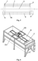
- Fig. 6 shows a perspective view of another embodiment of the invention wherein the exchanger assembly is placed in the tub
- Fig. 7 shows a perspective view of the tub together with the exchanger assembly according to the same embodiment in the longitudinal section
- Fig. 8 shows a schematic axial view of the movement of the exchanger in the same embodiment
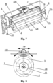
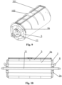
- Fig. 9 shows a perspective view of the exchanger assembly in the same embodiment
- Fig. 10 shows a cross-sectional view of the exchanger in the same embodiment.
- the drawings show embodiments of the present invention wherein it is common to all the embodiments that the invention is a heat exchanger assembly which is immersed in a fluid.
- the heat exchanger assembly comprises an arrangement of shells 3 wherein the shells 3 are in fluid communication with each other and closed at both ends, forming a heat exchange chamber. Between the shells, there are spaces 3a open at both ends through which the fluid in which the exchanger is immersed flows freely.
- Figs. 2 , 4 , 7 , 10 Fig. 1 further shows that the exchanger is placed in the tub (W), i.e. immersed in a fluid such as wastewater.
- the assembly is fitted with supply means 6,7,10a that feed another fluid into the shells 3, and with drain means 8,9,10 that drain said fluid from the shells 3.
- the shells 3 are arranged and permanently fixed around the cylindrical chamber 1 and rotating with the shaft 11 and the cylindrical chamber 1, while the shaft 11, the cylindrical chamber 1 and the shells 3 are arranged concentrically.
- the exchanger assembly may comprise one or more shells 3, the most preferred number of shells 3 being one, two or three.
- Figs. 1-5 show an embodiment with three shells 3 (one of the preferred embodiments of the exchanger assembly wherein a motor is provided that swings the shaft forward and backward), while Figs. 6-10 show an embodiment with only one shell 3 (the preferred embodiment of the exchanger assembly wherein a vibration motor is provided).
- shells 3 are separated using perforated partition walls 4, as shown in the embodiment of, among others, Fig. 2 , and - equally preferably - are closed at both ends using ring-shaped lids 5 ( Fig. 3 ).
- the cylindrical chamber 1 has manifolds 2a at its ends, which are connected to the arrangement of shells 3 via radially arranged supply pipes 7, preferably there are six supply pipes 7 ( Fig. 3 ).
- the arrangement of shells 3 is mounted around the cylindrical chamber 1 by means of radial connectors 3,4, preferably four ( Figs. 3,4 ).
- the supply means 6,7,10a comprise a stub supply pipe 10a, a main supply pipe 6 and distribution pipes 7.
- the drain means (8,9,10) comprise collecting pipes 8, a main drain pipe 9 and a stub drain pipe 10.
- the driving unit 100 constitutes an electric motor that swings the shaft 11 forward and backward.
- the electric motor 100 is adapted to swing the shaft 11 forward and backward within a range of ⁇ 15° over a time period of approx. 1s.
- the driving unit 100 constitutes a vibration motor.
- the vibration motor 100 is adapted to move the exchanger relative to axis of the shaft 11 with a frequency of approx. 17 Hz and an amplitude of approx. 2 mm ( ⁇ u); the arrow in Fig. 10 indicates the direction of the vibrations.
- the exchanger assembly is preferably provided with a frame 101 with a mounting plate 102 on which a vibration motor 100 is mounted.
- the exchanger assembly e.g. intended for use in laundry activities, can be installed in the chamber (tub) W, which is also a supporting structure for the heat exchanger and the drive system with motor 100, and a tank for a fluid therein, e.g. wastewater, from which heat is received.
- the frame structure of the tub can be formed by a frame welded from steel profiles, while tank Z (shown in Fig. 1 ), which forms an initial buffer for the flow from wastewater and receives the filtered water from the laundry, can be installed in the upper part of the frame.
- the water is fed into the tub through tubing by gravity (not shown).
- the system can be provided with means for preventing overflow.
- the motor 100 in an embodiment of the present invention wherein said motor makes the shaft swing forward and backward, can be mounted on the shorter side wall of tub W, as shown in Figs. 1-2 .
- said motor can be mounted above the exchanger assembly, e.g. using frame 101 with mounting plate 102, as clearly seen in Figs. 6-8 .
- a boundary layer "becomes detached", which prevents efficient heat transfer.
- the exchanger is cleaned when it moves.
- a cylindrical air-filled chamber mounted on the shaft and moving therewith moves relative to the fluid in the exchanger so that the stream of fluid runs parallel to the axis of said chamber.
- the flow of the fluid is determined by the geometry of the heat exchanger. Since the element operates under pressure, in the present invention, the chamber arranged around the shaft "takes away" a significant part of the load, which is essential to energy (heat) recovery.
- the casing is typically made of stainless steel, which performs poorly in heat exchangers due to its low lambda value - the rate at which heat passes through a material. This can be improved by increasing the heat exchange surface by making the metal sheet thicker (water pressure hazard). The disadvantage of such a solution is an increase in weight. Therefore, the central chamber arranged around the shaft is essential to the present invention.
- the chamber also cleans itself as a result of the movement due to the inertial force of the fluid.
- Another function of the chamber is that supporting points (bearings) of the exchanger as a whole are less loaded due to the buoyancy of said chamber.
- the pressure load can be around 1000T.
- the construction design must be strong, which requires the use of a fairly thick sheet of considerable weight. Under certain conditions, the central chamber on the shaft can take up to 300 kg away from the shaft, resulting in the construction design being less loaded.
Landscapes
- Engineering & Computer Science (AREA)
- Mechanical Engineering (AREA)
- General Engineering & Computer Science (AREA)
- Physics & Mathematics (AREA)
- Thermal Sciences (AREA)
- Chemical & Material Sciences (AREA)
- Combustion & Propulsion (AREA)
- Heat-Exchange Devices With Radiators And Conduit Assemblies (AREA)
Claims (18)
- Eine Wärmetauscher-Anordnung zum Eintauchen in Flüssigkeit mit einem Mantelsystem (3) mit mindestens einem Mantel (3), das an seinen beiden Enden geschlossen ist und eine Wärmeaustauschkammer und eine Anzahl von Räumen (3a), abhängig von der Anzahl der Mäntel (3) bildet, die anliegend und radial innerhalb des jeden Mantels (3) angeordnet sind, durch die die Flüssigkeit, in der der Tauscher eingetaucht ist, frei fließen kann, wobei das System mit Zulaufmitteln (6, 7, 10a), die eine weitere Flüssigkeit in den Mantel (3) einspeisen, und mit Ablaufmitteln (8, 9, 10), die die Flüssigkeit aus dem Mantel (3) abführen, ausgestattet ist, umfassend:- eine zentrale Welle (11), die an ihren beiden Enden drehbar gelagert ist,- eine zylindrische Kammer (1), die um die Welle (11) herum angeordnet ist, wobei die zylindrische Kammer (1), dauerhaft und hermetisch um die Welle (11) herum befestigt ist und sich mit der Welle (11) dreht, und mit Luft gefüllt ist und- eine Antriebseinheit (100) zum Bewegen der Wärmetauscher-Anordnung,
dadurch gekennzeichnet, dass die Räume (3a) entsprechend der Anzahl der Mäntel (3) an den beiden Enden geöffnet sind und dass das Mantelsystem (3) die zylindrische Kammer (1) umgibt und dauerhaft daran befestigt ist und sich zusammen mit der Welle (11) und der zylindrischen Kammer (1) dreht, während die Welle (11), die zylindrische Kammer (1) und der Mantel (3) konzentrisch angeordnet sind. - Die Wärmetauscher-Anordnung nach Anspruch 1, dadurch gekennzeichnet, dass sie einen Mantel (3) umfasst.
- Die Wärmetauscher-Anordnung nach Anspruch 1, dadurch gekennzeichnet, dass sie mindestens zwei Mäntel (3) umfasst und die Mäntel (3) miteinander in Fluidkommunikation sind und zusammen eine Wärmeaustauschkammer bilden.
- Die Wärmetauscher-Anordnung nach Anspruch 3, dadurch gekennzeichnet, dass sie drei Mäntel umfasst.
- Die Wärmetauscher-Anordnung nach Anspruch 1, dadurch gekennzeichnet, dass sie eine gerade Anzahl von Mänteln (3) umfasst, die miteinander paarweise in Fluidverbindung sind, wobei jedes Paar eine Wärmeaustauschkammer bildet.
- Die Wärmetauscher-Anordnung nach einem der Ansprüche 3 - 5, dadurch gekennzeichnet, dass die Mäntel (3) über perforierte Trennwände (4) miteinander verbunden sind.
- Die Wärmetauscher-Anordnung nach Anspruch 1, dadurch gekennzeichnet, dass die Mäntel (3) an ihren beiden Enden mit ringförmigen Deckeln (5) verschlossen sind.
- Die Wärmetauscher-Anordnung nach Anspruch 1, dadurch gekennzeichnet, dass die zylindrische Kammer (1) an ihren Enden Kollektoren (2a) aufweist, die über radial angeordnete Zulaufrohre (7) an das Mantelsystem (3) angeschlossen sind.
- Die Wärmetauscher-Anordnung nach Anspruch 8, dadurch gekennzeichnet, dass sie sechs Zulaufrohre (7) umfasst.
- Die Wärmetauscher-Anordnung nach Anspruch 1, dadurch gekennzeichnet, dass das Mantelsystem (3) mithilfe radialer Verbinder (2) um die zylindrische Kammer (1) herum montiert ist.
- Die Wärmetauscher-Anordnung nach Anspruch 10, gekennzeichnet durch vier radiale Verbinder (2).
- Die Wärmetauscher-Anordnung nach Anspruch 1, dadurch gekennzeichnet, dass die Zulaufmittel (6, 7, 10a) einen Zulaufstutzen (10a), ein Zulauf-Hauptrohr (6) und Verteilrohre (7) umfassen.
- Die Wärmetauscher-Anordnung nach Anspruch 1, dadurch gekennzeichnet, dass die Ablaufelemente (8, 9, 10) Sammelrohre (8), ein Ablauf-Hauptrohr (9) und einen Ablaufstutzen (10) umfassen.
- Die Wärmetauscher-Anordnung nach Anspruch 1, dadurch gekennzeichnet, dass die Antriebseinheit (100) ein Elektromotor ist, der die Welle (11) vorwärts und rückwärts schwingt.
- Die Wärmetauscher-Anordnung nach Anspruch 14, dadurch gekennzeichnet, dass der Elektromotor (100) so ausgelegt ist, dass er die Welle (11) vorwärts und rückwärts in einem Bereich von ±15° innerhalb der Zeit von ca. 1 s schwingen kann.
- Die Wärmetauscher-Anordnung nach Anspruch 1, dadurch gekennzeichnet, dass die Antriebseinheit (100) ein Vibrationsmotor ist.
- Die Wärmetauscher-Anordnung nach Anspruch 16, dadurch gekennzeichnet, dass der Vibrationsmotor (100) so ausgelegt ist, dass er den Tauscher relativ zur Achse der Welle (11) mit einer Frequenz von ca. 17 Hz und einer Amplitude von ca. 2 mm bewegen kann.
- Die Wärmetauscher-Anordnung nach Anspruch 16, dadurch gekennzeichnet, dass sie mit einem Rahmen (101) mit einer Montageplatte (102) versehen ist, auf der der Vibrationsmotor (100) montiert ist.
Applications Claiming Priority (1)
| Application Number | Priority Date | Filing Date | Title |
|---|---|---|---|
| PL438256A PL243377B1 (pl) | 2021-06-28 | 2021-06-28 | Zespół wymiennika ciepła |
Publications (3)
| Publication Number | Publication Date |
|---|---|
| EP4113045A1 EP4113045A1 (de) | 2023-01-04 |
| EP4113045B1 true EP4113045B1 (de) | 2024-04-24 |
| EP4113045C0 EP4113045C0 (de) | 2024-04-24 |
Family
ID=80682479
Family Applications (1)
| Application Number | Title | Priority Date | Filing Date |
|---|---|---|---|
| EP22151335.1A Active EP4113045B1 (de) | 2021-06-28 | 2022-01-13 | Wärmetauscherbaugruppe |
Country Status (2)
| Country | Link |
|---|---|
| EP (1) | EP4113045B1 (de) |
| PL (1) | PL243377B1 (de) |
Families Citing this family (1)
| Publication number | Priority date | Publication date | Assignee | Title |
|---|---|---|---|---|
| CN119022708B (zh) * | 2024-09-26 | 2025-04-01 | 无锡鼎邦换热设备股份有限公司 | 一种换热器 |
Family Cites Families (10)
| Publication number | Priority date | Publication date | Assignee | Title |
|---|---|---|---|---|
| GB656647A (en) | 1947-04-02 | 1951-08-29 | Lambertus Hendrik De Langen | Improvements in heat exchangers, liquid conveyors or condensers |
| US3235002A (en) * | 1963-11-07 | 1966-02-15 | Chemetron Corp | Heat exchange apparatus |
| US3363676A (en) * | 1964-10-05 | 1968-01-16 | North American Aviation Inc | Rotating heat exchanger |
| DE1794098A1 (de) | 1968-09-06 | 1971-11-18 | Escher Wyss Gmbh | Doppelmanteliger,rohrfoermiger Waermeaustauscher,insbesondere Kristallisationskuehler |
| BE757441A (fr) | 1969-10-14 | 1971-04-13 | Armstrong Richard M | Agencement pour monter des lames de raclage |
| DE2215536C2 (de) | 1972-03-30 | 1982-07-01 | Chocoladefabriken Lindt & Sprüngli AG, Kilchberg, Zürich | Vorrichtung zur Aufbereitung von noch fließfähiger Schokolademasse |
| US6471392B1 (en) * | 2001-03-07 | 2002-10-29 | Holl Technologies Company | Methods and apparatus for materials processing |
| PL203017B1 (pl) * | 2004-10-30 | 2009-08-31 | Henryk Nowak | Wymiennik ciepła |
| DK2684004T3 (en) * | 2011-03-11 | 2017-01-09 | Blentech Corp | Heat exchanger with multiple surfaces with the possibility vacuo and magnetic scrapers |
| CN105727581A (zh) * | 2016-05-11 | 2016-07-06 | 南京工业大学 | 一种蒸汽加热的多层薄膜蒸发器 |
-
2021
- 2021-06-28 PL PL438256A patent/PL243377B1/pl unknown
-
2022
- 2022-01-13 EP EP22151335.1A patent/EP4113045B1/de active Active
Also Published As
| Publication number | Publication date |
|---|---|
| EP4113045A1 (de) | 2023-01-04 |
| PL243377B1 (pl) | 2023-08-14 |
| PL438256A1 (pl) | 2023-01-02 |
| EP4113045C0 (de) | 2024-04-24 |
Similar Documents
| Publication | Publication Date | Title |
|---|---|---|
| US20030005825A1 (en) | Method & apparatus for cleaning a gas | |
| EP4113045B1 (de) | Wärmetauscherbaugruppe | |
| JP2006517144A (ja) | 濾過装置、濾材および濾過方法 | |
| JP6618818B2 (ja) | 多管式熱交換器、その伝熱管洗浄方法 | |
| CN116718046A (zh) | 一种列管式换热器及强制循环蒸发分离器 | |
| JP2008116196A (ja) | 管式熱交換器 | |
| US3721129A (en) | Eccentric system for vibratory earth compactor | |
| KR20120105073A (ko) | 수직형 회전 마찰 가열기 | |
| KR940701293A (ko) | 연도가스 정화장치 | |
| US8123047B2 (en) | Filter for fluids in conduits | |
| US5597036A (en) | Balanced drive with radially slotted countercrank for orbital tube whip rod heat exchanger | |
| SU1567117A3 (ru) | Сгуститель | |
| CN110057210A (zh) | 一种污水源换热器 | |
| CN214990395U (zh) | 一种自动脱气排污装置 | |
| SU1158846A1 (ru) | Теплообменник | |
| CN213421955U (zh) | 一种换热器清洗装置及风管机 | |
| CN209991814U (zh) | 一种污水源换热器 | |
| CN110563305B (zh) | 一种圆盘干燥机及其排水结构 | |
| RU2072491C1 (ru) | Теплообменный аппарат | |
| CN223726056U (zh) | 一种蒸汽管网冷凝水排放装置 | |
| CN209894002U (zh) | 一种用于泳池的换热器 | |
| RU2825686C2 (ru) | Установка насоса | |
| JPH09109367A (ja) | 印刷装置のウエブ冷却ローラ | |
| CN212143089U (zh) | 一种离心机进料管自清洗装置 | |
| RU2317127C1 (ru) | Выпарной аппарат для радиоактивных растворов |
Legal Events
| Date | Code | Title | Description |
|---|---|---|---|
| PUAI | Public reference made under article 153(3) epc to a published international application that has entered the european phase |
Free format text: ORIGINAL CODE: 0009012 |
|
| STAA | Information on the status of an ep patent application or granted ep patent |
Free format text: STATUS: REQUEST FOR EXAMINATION WAS MADE |
|
| 17P | Request for examination filed |
Effective date: 20220113 |
|
| AK | Designated contracting states |
Kind code of ref document: A1 Designated state(s): AL AT BE BG CH CY CZ DE DK EE ES FI FR GB GR HR HU IE IS IT LI LT LU LV MC MK MT NL NO PL PT RO RS SE SI SK SM TR |
|
| GRAP | Despatch of communication of intention to grant a patent |
Free format text: ORIGINAL CODE: EPIDOSNIGR1 |
|
| STAA | Information on the status of an ep patent application or granted ep patent |
Free format text: STATUS: GRANT OF PATENT IS INTENDED |
|
| RIC1 | Information provided on ipc code assigned before grant |
Ipc: F28D 21/00 20060101ALI20231031BHEP Ipc: F28F 5/02 20060101ALI20231031BHEP Ipc: F28D 11/06 20060101ALI20231031BHEP Ipc: F28D 11/02 20060101ALI20231031BHEP Ipc: F28F 9/02 20060101ALI20231031BHEP Ipc: F28G 7/00 20060101ALI20231031BHEP Ipc: F28D 7/10 20060101ALI20231031BHEP Ipc: D06F 39/00 20200101ALI20231031BHEP Ipc: F28D 1/02 20060101AFI20231031BHEP |
|
| INTG | Intention to grant announced |
Effective date: 20231122 |
|
| GRAS | Grant fee paid |
Free format text: ORIGINAL CODE: EPIDOSNIGR3 |
|
| GRAA | (expected) grant |
Free format text: ORIGINAL CODE: 0009210 |
|
| STAA | Information on the status of an ep patent application or granted ep patent |
Free format text: STATUS: THE PATENT HAS BEEN GRANTED |
|
| AK | Designated contracting states |
Kind code of ref document: B1 Designated state(s): AL AT BE BG CH CY CZ DE DK EE ES FI FR GB GR HR HU IE IS IT LI LT LU LV MC MK MT NL NO PL PT RO RS SE SI SK SM TR |
|
| REG | Reference to a national code |
Ref country code: GB Ref legal event code: FG4D |
|
| REG | Reference to a national code |
Ref country code: CH Ref legal event code: EP |
|
| REG | Reference to a national code |
Ref country code: DE Ref legal event code: R096 Ref document number: 602022002963 Country of ref document: DE |
|
| REG | Reference to a national code |
Ref country code: IE Ref legal event code: FG4D |
|
| U01 | Request for unitary effect filed |
Effective date: 20240517 |
|
| U07 | Unitary effect registered |
Designated state(s): AT BE BG DE DK EE FI FR IT LT LU LV MT NL PT SE SI Effective date: 20240528 |
|
| PG25 | Lapsed in a contracting state [announced via postgrant information from national office to epo] |
Ref country code: IS Free format text: LAPSE BECAUSE OF FAILURE TO SUBMIT A TRANSLATION OF THE DESCRIPTION OR TO PAY THE FEE WITHIN THE PRESCRIBED TIME-LIMIT Effective date: 20240824 |
|
| PG25 | Lapsed in a contracting state [announced via postgrant information from national office to epo] |
Ref country code: HR Free format text: LAPSE BECAUSE OF FAILURE TO SUBMIT A TRANSLATION OF THE DESCRIPTION OR TO PAY THE FEE WITHIN THE PRESCRIBED TIME-LIMIT Effective date: 20240424 |
|
| PG25 | Lapsed in a contracting state [announced via postgrant information from national office to epo] |
Ref country code: GR Free format text: LAPSE BECAUSE OF FAILURE TO SUBMIT A TRANSLATION OF THE DESCRIPTION OR TO PAY THE FEE WITHIN THE PRESCRIBED TIME-LIMIT Effective date: 20240725 |
|
| PG25 | Lapsed in a contracting state [announced via postgrant information from national office to epo] |
Ref country code: ES Free format text: LAPSE BECAUSE OF FAILURE TO SUBMIT A TRANSLATION OF THE DESCRIPTION OR TO PAY THE FEE WITHIN THE PRESCRIBED TIME-LIMIT Effective date: 20240424 |
|
| PG25 | Lapsed in a contracting state [announced via postgrant information from national office to epo] |
Ref country code: PL Free format text: LAPSE BECAUSE OF FAILURE TO SUBMIT A TRANSLATION OF THE DESCRIPTION OR TO PAY THE FEE WITHIN THE PRESCRIBED TIME-LIMIT Effective date: 20240424 |
|
| PG25 | Lapsed in a contracting state [announced via postgrant information from national office to epo] |
Ref country code: PL Free format text: LAPSE BECAUSE OF FAILURE TO SUBMIT A TRANSLATION OF THE DESCRIPTION OR TO PAY THE FEE WITHIN THE PRESCRIBED TIME-LIMIT Effective date: 20240424 Ref country code: NO Free format text: LAPSE BECAUSE OF FAILURE TO SUBMIT A TRANSLATION OF THE DESCRIPTION OR TO PAY THE FEE WITHIN THE PRESCRIBED TIME-LIMIT Effective date: 20240724 Ref country code: IS Free format text: LAPSE BECAUSE OF FAILURE TO SUBMIT A TRANSLATION OF THE DESCRIPTION OR TO PAY THE FEE WITHIN THE PRESCRIBED TIME-LIMIT Effective date: 20240824 Ref country code: HR Free format text: LAPSE BECAUSE OF FAILURE TO SUBMIT A TRANSLATION OF THE DESCRIPTION OR TO PAY THE FEE WITHIN THE PRESCRIBED TIME-LIMIT Effective date: 20240424 Ref country code: GR Free format text: LAPSE BECAUSE OF FAILURE TO SUBMIT A TRANSLATION OF THE DESCRIPTION OR TO PAY THE FEE WITHIN THE PRESCRIBED TIME-LIMIT Effective date: 20240725 Ref country code: ES Free format text: LAPSE BECAUSE OF FAILURE TO SUBMIT A TRANSLATION OF THE DESCRIPTION OR TO PAY THE FEE WITHIN THE PRESCRIBED TIME-LIMIT Effective date: 20240424 Ref country code: RS Free format text: LAPSE BECAUSE OF FAILURE TO SUBMIT A TRANSLATION OF THE DESCRIPTION OR TO PAY THE FEE WITHIN THE PRESCRIBED TIME-LIMIT Effective date: 20240724 |
|
| U20 | Renewal fee for the european patent with unitary effect paid |
Year of fee payment: 4 Effective date: 20241211 |
|
| PG25 | Lapsed in a contracting state [announced via postgrant information from national office to epo] |
Ref country code: CZ Free format text: LAPSE BECAUSE OF FAILURE TO SUBMIT A TRANSLATION OF THE DESCRIPTION OR TO PAY THE FEE WITHIN THE PRESCRIBED TIME-LIMIT Effective date: 20240424 |
|
| PG25 | Lapsed in a contracting state [announced via postgrant information from national office to epo] |
Ref country code: SK Free format text: LAPSE BECAUSE OF FAILURE TO SUBMIT A TRANSLATION OF THE DESCRIPTION OR TO PAY THE FEE WITHIN THE PRESCRIBED TIME-LIMIT Effective date: 20240424 Ref country code: RO Free format text: LAPSE BECAUSE OF FAILURE TO SUBMIT A TRANSLATION OF THE DESCRIPTION OR TO PAY THE FEE WITHIN THE PRESCRIBED TIME-LIMIT Effective date: 20240424 |
|
| REG | Reference to a national code |
Ref country code: DE Ref legal event code: R097 Ref document number: 602022002963 Country of ref document: DE |
|
| PG25 | Lapsed in a contracting state [announced via postgrant information from national office to epo] |
Ref country code: SM Free format text: LAPSE BECAUSE OF FAILURE TO SUBMIT A TRANSLATION OF THE DESCRIPTION OR TO PAY THE FEE WITHIN THE PRESCRIBED TIME-LIMIT Effective date: 20240424 |
|
| PG25 | Lapsed in a contracting state [announced via postgrant information from national office to epo] |
Ref country code: SM Free format text: LAPSE BECAUSE OF FAILURE TO SUBMIT A TRANSLATION OF THE DESCRIPTION OR TO PAY THE FEE WITHIN THE PRESCRIBED TIME-LIMIT Effective date: 20240424 Ref country code: SK Free format text: LAPSE BECAUSE OF FAILURE TO SUBMIT A TRANSLATION OF THE DESCRIPTION OR TO PAY THE FEE WITHIN THE PRESCRIBED TIME-LIMIT Effective date: 20240424 Ref country code: RO Free format text: LAPSE BECAUSE OF FAILURE TO SUBMIT A TRANSLATION OF THE DESCRIPTION OR TO PAY THE FEE WITHIN THE PRESCRIBED TIME-LIMIT Effective date: 20240424 Ref country code: CZ Free format text: LAPSE BECAUSE OF FAILURE TO SUBMIT A TRANSLATION OF THE DESCRIPTION OR TO PAY THE FEE WITHIN THE PRESCRIBED TIME-LIMIT Effective date: 20240424 |
|
| PLBE | No opposition filed within time limit |
Free format text: ORIGINAL CODE: 0009261 |
|
| STAA | Information on the status of an ep patent application or granted ep patent |
Free format text: STATUS: NO OPPOSITION FILED WITHIN TIME LIMIT |
|
| 26N | No opposition filed |
Effective date: 20250127 |
|
| REG | Reference to a national code |
Ref country code: CH Ref legal event code: PL |
|
| PG25 | Lapsed in a contracting state [announced via postgrant information from national office to epo] |
Ref country code: MC Free format text: LAPSE BECAUSE OF FAILURE TO SUBMIT A TRANSLATION OF THE DESCRIPTION OR TO PAY THE FEE WITHIN THE PRESCRIBED TIME-LIMIT Effective date: 20240424 |
|
| PG25 | Lapsed in a contracting state [announced via postgrant information from national office to epo] |
Ref country code: CH Free format text: LAPSE BECAUSE OF NON-PAYMENT OF DUE FEES Effective date: 20250131 |
|
| U20 | Renewal fee for the european patent with unitary effect paid |
Year of fee payment: 5 Effective date: 20251125 |
|
| PG25 | Lapsed in a contracting state [announced via postgrant information from national office to epo] |
Ref country code: IE Free format text: LAPSE BECAUSE OF NON-PAYMENT OF DUE FEES Effective date: 20250113 |