EP4113045B1 - Heat exchanger assembly - Google Patents
Heat exchanger assembly Download PDFInfo
- Publication number
- EP4113045B1 EP4113045B1 EP22151335.1A EP22151335A EP4113045B1 EP 4113045 B1 EP4113045 B1 EP 4113045B1 EP 22151335 A EP22151335 A EP 22151335A EP 4113045 B1 EP4113045 B1 EP 4113045B1
- Authority
- EP
- European Patent Office
- Prior art keywords
- exchanger assembly
- assembly according
- shaft
- shells
- exchanger
- Prior art date
- Legal status (The legal status is an assumption and is not a legal conclusion. Google has not performed a legal analysis and makes no representation as to the accuracy of the status listed.)
- Active
Links
- 239000012530 fluid Substances 0.000 claims description 41
- 238000004891 communication Methods 0.000 claims description 5
- 238000005192 partition Methods 0.000 claims description 4
- 239000002351 wastewater Substances 0.000 description 6
- 238000010276 construction Methods 0.000 description 3
- 239000000463 material Substances 0.000 description 3
- XLYOFNOQVPJJNP-UHFFFAOYSA-N water Substances O XLYOFNOQVPJJNP-UHFFFAOYSA-N 0.000 description 3
- 239000002184 metal Substances 0.000 description 2
- 238000012986 modification Methods 0.000 description 2
- 230000004048 modification Effects 0.000 description 2
- 229910000831 Steel Inorganic materials 0.000 description 1
- 238000004140 cleaning Methods 0.000 description 1
- 230000000694 effects Effects 0.000 description 1
- 230000005484 gravity Effects 0.000 description 1
- 238000011084 recovery Methods 0.000 description 1
- 229910001220 stainless steel Inorganic materials 0.000 description 1
- 239000010935 stainless steel Substances 0.000 description 1
- 239000010959 steel Substances 0.000 description 1
Images


Classifications
-
- F—MECHANICAL ENGINEERING; LIGHTING; HEATING; WEAPONS; BLASTING
- F28—HEAT EXCHANGE IN GENERAL
- F28D—HEAT-EXCHANGE APPARATUS, NOT PROVIDED FOR IN ANOTHER SUBCLASS, IN WHICH THE HEAT-EXCHANGE MEDIA DO NOT COME INTO DIRECT CONTACT
- F28D1/00—Heat-exchange apparatus having stationary conduit assemblies for one heat-exchange medium only, the media being in contact with different sides of the conduit wall, in which the other heat-exchange medium is a large body of fluid, e.g. domestic or motor car radiators
- F28D1/02—Heat-exchange apparatus having stationary conduit assemblies for one heat-exchange medium only, the media being in contact with different sides of the conduit wall, in which the other heat-exchange medium is a large body of fluid, e.g. domestic or motor car radiators with heat-exchange conduits immersed in the body of fluid
- F28D1/0206—Heat exchangers immersed in a large body of liquid
- F28D1/0213—Heat exchangers immersed in a large body of liquid for heating or cooling a liquid in a tank
-
- F—MECHANICAL ENGINEERING; LIGHTING; HEATING; WEAPONS; BLASTING
- F28—HEAT EXCHANGE IN GENERAL
- F28D—HEAT-EXCHANGE APPARATUS, NOT PROVIDED FOR IN ANOTHER SUBCLASS, IN WHICH THE HEAT-EXCHANGE MEDIA DO NOT COME INTO DIRECT CONTACT
- F28D11/00—Heat-exchange apparatus employing moving conduits
- F28D11/02—Heat-exchange apparatus employing moving conduits the movement being rotary, e.g. performed by a drum or roller
-
- F—MECHANICAL ENGINEERING; LIGHTING; HEATING; WEAPONS; BLASTING
- F28—HEAT EXCHANGE IN GENERAL
- F28D—HEAT-EXCHANGE APPARATUS, NOT PROVIDED FOR IN ANOTHER SUBCLASS, IN WHICH THE HEAT-EXCHANGE MEDIA DO NOT COME INTO DIRECT CONTACT
- F28D11/00—Heat-exchange apparatus employing moving conduits
- F28D11/06—Heat-exchange apparatus employing moving conduits the movement being reciprocating or oscillating
-
- F—MECHANICAL ENGINEERING; LIGHTING; HEATING; WEAPONS; BLASTING
- F28—HEAT EXCHANGE IN GENERAL
- F28D—HEAT-EXCHANGE APPARATUS, NOT PROVIDED FOR IN ANOTHER SUBCLASS, IN WHICH THE HEAT-EXCHANGE MEDIA DO NOT COME INTO DIRECT CONTACT
- F28D21/00—Heat-exchange apparatus not covered by any of the groups F28D1/00 - F28D20/00
- F28D21/0001—Recuperative heat exchangers
- F28D21/0012—Recuperative heat exchangers the heat being recuperated from waste water or from condensates
-
- F—MECHANICAL ENGINEERING; LIGHTING; HEATING; WEAPONS; BLASTING
- F28—HEAT EXCHANGE IN GENERAL
- F28D—HEAT-EXCHANGE APPARATUS, NOT PROVIDED FOR IN ANOTHER SUBCLASS, IN WHICH THE HEAT-EXCHANGE MEDIA DO NOT COME INTO DIRECT CONTACT
- F28D7/00—Heat-exchange apparatus having stationary tubular conduit assemblies for both heat-exchange media, the media being in contact with different sides of a conduit wall
- F28D7/10—Heat-exchange apparatus having stationary tubular conduit assemblies for both heat-exchange media, the media being in contact with different sides of a conduit wall the conduits being arranged one within the other, e.g. concentrically
- F28D7/103—Heat-exchange apparatus having stationary tubular conduit assemblies for both heat-exchange media, the media being in contact with different sides of a conduit wall the conduits being arranged one within the other, e.g. concentrically consisting of more than two coaxial conduits or modules of more than two coaxial conduits
-
- F—MECHANICAL ENGINEERING; LIGHTING; HEATING; WEAPONS; BLASTING
- F28—HEAT EXCHANGE IN GENERAL
- F28F—DETAILS OF HEAT-EXCHANGE AND HEAT-TRANSFER APPARATUS, OF GENERAL APPLICATION
- F28F5/00—Elements specially adapted for movement
- F28F5/02—Rotary drums or rollers
-
- F—MECHANICAL ENGINEERING; LIGHTING; HEATING; WEAPONS; BLASTING
- F28—HEAT EXCHANGE IN GENERAL
- F28F—DETAILS OF HEAT-EXCHANGE AND HEAT-TRANSFER APPARATUS, OF GENERAL APPLICATION
- F28F9/00—Casings; Header boxes; Auxiliary supports for elements; Auxiliary members within casings
- F28F9/02—Header boxes; End plates
- F28F9/026—Header boxes; End plates with static flow control means, e.g. with means for uniformly distributing heat exchange media into conduits
- F28F9/027—Header boxes; End plates with static flow control means, e.g. with means for uniformly distributing heat exchange media into conduits in the form of distribution pipes
- F28F9/0275—Header boxes; End plates with static flow control means, e.g. with means for uniformly distributing heat exchange media into conduits in the form of distribution pipes with multiple branch pipes
-
- F—MECHANICAL ENGINEERING; LIGHTING; HEATING; WEAPONS; BLASTING
- F28—HEAT EXCHANGE IN GENERAL
- F28G—CLEANING OF INTERNAL OR EXTERNAL SURFACES OF HEAT-EXCHANGE OR HEAT-TRANSFER CONDUITS, e.g. WATER TUBES OR BOILERS
- F28G7/00—Cleaning by vibration or pressure waves
Definitions
- This invention relates to a heat exchanger assembly to be immersed in a fluid comprising an arrangement of shells wherein the shells are in fluid communication with each other and closed at both ends, forming a heat exchange chamber, while between the shells there are spaces open at both ends through which the fluid in which the exchanger is immersed flows freely, and the assembly is fitted with supply means that feed another fluid into the shells, and with drain means that drain said fluid from the shells.
- WO 2012/125586 A1 discloses a heat exchanger assembly with the features of the preamble of claim 1.
- Shell heat exchangers wherein shells are in fluid communication with each other and closed at both ends, with spaces being provided between said shells.
- the first fluid flows through the shells forming a heat exchange chamber, while the second fluid flows in the spaces between the shells.
- one fluid transfers heat to another fluid.
- the disadvantage of this heat exchange system is that the fluid on both sides of the metal sheet formed by shells creates a boundary layer. This layer prevents efficient heat exchange. Accordingly, such exchangers are often put into motion, e.g.
- GB656647A discloses a rotary exchanger mounted on a shaft.
- the exchanger is set into rotary motion to facilitate the flow of fluids through the exchanger and the transfer of heat.
- Both ends of the rotating shaft are hollow and designed to supply the fluid to the exchanger and drain the fluid into one of the ducts, while the other fluid is fed into and discharged through stub pipes in the casing.
- JPS54114851A discloses a rotary exchanger mounted on a shaft.
- the shaft is hollow and designed to supply the medium to certain chambers of the exchanger.
- GB1239320A discloses a shell exchanger with a hollow rotating shaft extending therethrough, the shaft being the only rotating element.
- a spiral element is fastened to the shaft to move the material within the chamber adjacent to the shaft, with scratch-off elements for cleaning the outer wall of the crystallising material being fastened to said shaft.
- the hollow shaft allows users to regulate the contact pressure of the scratch-off elements by applying a required level of pressure.
- US3621506A discloses a similar device, also provided with a hollow rotating shaft to which scratch-off elements are attached.
- US3835922A discloses a device wherein a cylindrical rotor is mounted around the rotating shaft (the hollow cylindrical chamber with flattened areas). Scratch-off elements are fastened to the rotor, as in the previous two patent disclosures.
- the rotor is designed to have a large diameter so that higher speeds of the scratch-off elements can be achieved.
- the object of the present invention is to increase the efficiency of existing devices by:
- the present invention relates to a heat exchanger assembly to be immersed in a fluid.
- the heat exchanger comprises an arrangement of shells wherein the shells are in fluid communication with each other and closed at both ends, forming a heat exchange chamber. Between the shells, there are spaces open at both ends through which the fluid in which the exchanger is immersed flows freely.
- the assembly is fitted with supply means that feed another fluid into the shells, and with drain means that drain said fluid from the shells (3).
- the heat exchanger assembly comprises:
- the exchanger assembly comprises one, two or three shells.
- the shells are fluidly coupled in pairs, each pair forming a heat exchange chamber.
- the shells are connected via perforated partition walls.
- the shells are closed at both ends using ring-shaped lids.
- the cylindrical chamber has manifolds at its ends, which are connected to the arrangement of shells via radially arranged supply pipes.
- supply pipes There are six supply pipes in the preferred embodiment.
- the arrangement of shells is arranged around the cylindrical chamber by means of radial connectors.
- radial connectors There are preferably four such connectors.
- the supply means comprise a stub supply pipe, a main supply pipe and distribution pipes.
- the drain means comprise collecting pipes, a main drain pipe and a stub drain pipe.
- the driving unit constitutes an electric motor that swings the shaft forward and backward.
- the swinging movement is preferably within a range of ⁇ 15° over a time period of approx. 1s.
- the driving unit equally preferably constitutes a vibration motor.
- the vibration motor is preferably adapted to move the exchanger relative to axis of the shaft with a frequency of approx. 17 Hz and an amplitude of approx. 2 mm.
- the exchanger assembly is provided with a frame with a mounting plate on which a vibration motor is mounted.
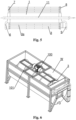
- Fig. 1 shows a perspective view of one embodiment of the present invention wherein the exchanger assembly is placed in the tub
- Fig. 2 shows a perspective view of the tub with the assembly according to the same embodiment in the longitudinal section
- Fig. 3 shows a perspective view of the exchanger assembly in the same embodiment
- Fig. 4 shows a cross-sectional view of the exchanger assembly in the same embodiment
- Fig. 5 shows a longitudinal section of the exchanger assembly in the same embodiment
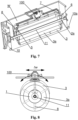
- Fig. 6 shows a perspective view of another embodiment of the invention wherein the exchanger assembly is placed in the tub
- Fig. 7 shows a perspective view of the tub together with the exchanger assembly according to the same embodiment in the longitudinal section
- Fig. 8 shows a schematic axial view of the movement of the exchanger in the same embodiment
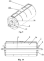
- Fig. 9 shows a perspective view of the exchanger assembly in the same embodiment
- Fig. 10 shows a cross-sectional view of the exchanger in the same embodiment.
- the drawings show embodiments of the present invention wherein it is common to all the embodiments that the invention is a heat exchanger assembly which is immersed in a fluid.
- the heat exchanger assembly comprises an arrangement of shells 3 wherein the shells 3 are in fluid communication with each other and closed at both ends, forming a heat exchange chamber. Between the shells, there are spaces 3a open at both ends through which the fluid in which the exchanger is immersed flows freely.
- Figs. 2 , 4 , 7 , 10 Fig. 1 further shows that the exchanger is placed in the tub (W), i.e. immersed in a fluid such as wastewater.
- the assembly is fitted with supply means 6,7,10a that feed another fluid into the shells 3, and with drain means 8,9,10 that drain said fluid from the shells 3.
- the shells 3 are arranged and permanently fixed around the cylindrical chamber 1 and rotating with the shaft 11 and the cylindrical chamber 1, while the shaft 11, the cylindrical chamber 1 and the shells 3 are arranged concentrically.
- the exchanger assembly may comprise one or more shells 3, the most preferred number of shells 3 being one, two or three.
- Figs. 1-5 show an embodiment with three shells 3 (one of the preferred embodiments of the exchanger assembly wherein a motor is provided that swings the shaft forward and backward), while Figs. 6-10 show an embodiment with only one shell 3 (the preferred embodiment of the exchanger assembly wherein a vibration motor is provided).
- shells 3 are separated using perforated partition walls 4, as shown in the embodiment of, among others, Fig. 2 , and - equally preferably - are closed at both ends using ring-shaped lids 5 ( Fig. 3 ).
- the cylindrical chamber 1 has manifolds 2a at its ends, which are connected to the arrangement of shells 3 via radially arranged supply pipes 7, preferably there are six supply pipes 7 ( Fig. 3 ).
- the arrangement of shells 3 is mounted around the cylindrical chamber 1 by means of radial connectors 3,4, preferably four ( Figs. 3,4 ).
- the supply means 6,7,10a comprise a stub supply pipe 10a, a main supply pipe 6 and distribution pipes 7.
- the drain means (8,9,10) comprise collecting pipes 8, a main drain pipe 9 and a stub drain pipe 10.
- the driving unit 100 constitutes an electric motor that swings the shaft 11 forward and backward.
- the electric motor 100 is adapted to swing the shaft 11 forward and backward within a range of ⁇ 15° over a time period of approx. 1s.
- the driving unit 100 constitutes a vibration motor.
- the vibration motor 100 is adapted to move the exchanger relative to axis of the shaft 11 with a frequency of approx. 17 Hz and an amplitude of approx. 2 mm ( ⁇ u); the arrow in Fig. 10 indicates the direction of the vibrations.
- the exchanger assembly is preferably provided with a frame 101 with a mounting plate 102 on which a vibration motor 100 is mounted.
- the exchanger assembly e.g. intended for use in laundry activities, can be installed in the chamber (tub) W, which is also a supporting structure for the heat exchanger and the drive system with motor 100, and a tank for a fluid therein, e.g. wastewater, from which heat is received.
- the frame structure of the tub can be formed by a frame welded from steel profiles, while tank Z (shown in Fig. 1 ), which forms an initial buffer for the flow from wastewater and receives the filtered water from the laundry, can be installed in the upper part of the frame.
- the water is fed into the tub through tubing by gravity (not shown).
- the system can be provided with means for preventing overflow.
- the motor 100 in an embodiment of the present invention wherein said motor makes the shaft swing forward and backward, can be mounted on the shorter side wall of tub W, as shown in Figs. 1-2 .
- said motor can be mounted above the exchanger assembly, e.g. using frame 101 with mounting plate 102, as clearly seen in Figs. 6-8 .
- a boundary layer "becomes detached", which prevents efficient heat transfer.
- the exchanger is cleaned when it moves.
- a cylindrical air-filled chamber mounted on the shaft and moving therewith moves relative to the fluid in the exchanger so that the stream of fluid runs parallel to the axis of said chamber.
- the flow of the fluid is determined by the geometry of the heat exchanger. Since the element operates under pressure, in the present invention, the chamber arranged around the shaft "takes away" a significant part of the load, which is essential to energy (heat) recovery.
- the casing is typically made of stainless steel, which performs poorly in heat exchangers due to its low lambda value - the rate at which heat passes through a material. This can be improved by increasing the heat exchange surface by making the metal sheet thicker (water pressure hazard). The disadvantage of such a solution is an increase in weight. Therefore, the central chamber arranged around the shaft is essential to the present invention.
- the chamber also cleans itself as a result of the movement due to the inertial force of the fluid.
- Another function of the chamber is that supporting points (bearings) of the exchanger as a whole are less loaded due to the buoyancy of said chamber.
- the pressure load can be around 1000T.
- the construction design must be strong, which requires the use of a fairly thick sheet of considerable weight. Under certain conditions, the central chamber on the shaft can take up to 300 kg away from the shaft, resulting in the construction design being less loaded.
Description
- This invention relates to a heat exchanger assembly to be immersed in a fluid comprising an arrangement of shells wherein the shells are in fluid communication with each other and closed at both ends, forming a heat exchange chamber, while between the shells there are spaces open at both ends through which the fluid in which the exchanger is immersed flows freely, and the assembly is fitted with supply means that feed another fluid into the shells, and with drain means that drain said fluid from the shells.
WO 2012/125586 A1 , for instance, discloses a heat exchanger assembly with the features of the preamble ofclaim 1. - Various types of shell and shell-and-tube heat exchangers are disclosed in the state of the art. Shell heat exchangers wherein shells are in fluid communication with each other and closed at both ends, with spaces being provided between said shells. The first fluid flows through the shells forming a heat exchange chamber, while the second fluid flows in the spaces between the shells. Through this arrangement, one fluid transfers heat to another fluid. The disadvantage of this heat exchange system is that the fluid on both sides of the metal sheet formed by shells creates a boundary layer. This layer prevents efficient heat exchange. Accordingly, such exchangers are often put into motion, e.g. made to rotate around their axis or made to vibrate, to facilitate the flow of fluids and the transfer of heat, and to prevent the build-up of deposits on the walls of the exchanger. The movement of the exchanger causes the boundary layer to "become detached", resulting in the exchanger being cleaned.
-
GB656647A - JPS54114851A discloses a rotary exchanger mounted on a shaft. The shaft is hollow and designed to supply the medium to certain chambers of the exchanger.
-
GB1239320A -
US3621506A discloses a similar device, also provided with a hollow rotating shaft to which scratch-off elements are attached. -
US3835922A discloses a device wherein a cylindrical rotor is mounted around the rotating shaft (the hollow cylindrical chamber with flattened areas). Scratch-off elements are fastened to the rotor, as in the previous two patent disclosures. The rotor is designed to have a large diameter so that higher speeds of the scratch-off elements can be achieved. - The object of the present invention is to increase the efficiency of existing devices by:
- facilitating the flow of fluid to improve the heat exchange and how the exchanger surface is cleaned.
- reducing loads on the bearings in shaft-based devices to increase their durability,
- stiffening the construction design to make it more efficient and durable.
- The present invention relates to a heat exchanger assembly to be immersed in a fluid. The heat exchanger comprises an arrangement of shells wherein the shells are in fluid communication with each other and closed at both ends, forming a heat exchange chamber. Between the shells, there are spaces open at both ends through which the fluid in which the exchanger is immersed flows freely. The assembly is fitted with supply means that feed another fluid into the shells, and with drain means that drain said fluid from the shells (3). According to the invention, the heat exchanger assembly comprises:
- a central shaft rotatably supported at both ends,
- a cylindrical chamber arranged around the shaft, said cylindrical chamber being permanently and hermetically fixed around the shaft and rotating with the shaft, and filled with air, and
- a driving unit for moving the exchanger assembly,
- Preferably, the exchanger assembly comprises one, two or three shells.
- Also preferably, the shells are fluidly coupled in pairs, each pair forming a heat exchange chamber.
- Also preferably, the shells are connected via perforated partition walls.
- It is also preferable if the shells are closed at both ends using ring-shaped lids.
- Preferably, the cylindrical chamber has manifolds at its ends, which are connected to the arrangement of shells via radially arranged supply pipes. There are six supply pipes in the preferred embodiment.
- Preferably, the arrangement of shells is arranged around the cylindrical chamber by means of radial connectors. There are preferably four such connectors.
- Also preferably, the supply means comprise a stub supply pipe, a main supply pipe and distribution pipes.
- Also preferably, the drain means comprise collecting pipes, a main drain pipe and a stub drain pipe.
- Also preferably, the driving unit constitutes an electric motor that swings the shaft forward and backward. The swinging movement is preferably within a range of ±15° over a time period of approx. 1s.
- The driving unit equally preferably constitutes a vibration motor. The vibration motor is preferably adapted to move the exchanger relative to axis of the shaft with a frequency of approx. 17 Hz and an amplitude of approx. 2 mm. Preferably, the exchanger assembly is provided with a frame with a mounting plate on which a vibration motor is mounted.
- The subject of the invention is shown in the embodiments of the invention in the drawing in which
Fig. 1 shows a perspective view of one embodiment of the present invention wherein the exchanger assembly is placed in the tub,Fig. 2 shows a perspective view of the tub with the assembly according to the same embodiment in the longitudinal section,Fig. 3 shows a perspective view of the exchanger assembly in the same embodiment,Fig. 4 shows a cross-sectional view of the exchanger assembly in the same embodiment,Fig. 5 shows a longitudinal section of the exchanger assembly in the same embodiment,Fig. 6 shows a perspective view of another embodiment of the invention wherein the exchanger assembly is placed in the tub,Fig. 7 shows a perspective view of the tub together with the exchanger assembly according to the same embodiment in the longitudinal section,Fig. 8 shows a schematic axial view of the movement of the exchanger in the same embodiment,Fig. 9 shows a perspective view of the exchanger assembly in the same embodiment,Fig. 10 shows a cross-sectional view of the exchanger in the same embodiment. - The drawings show embodiments of the present invention wherein it is common to all the embodiments that the invention is a heat exchanger assembly which is immersed in a fluid. The heat exchanger assembly comprises an arrangement of
shells 3 wherein theshells 3 are in fluid communication with each other and closed at both ends, forming a heat exchange chamber. Between the shells, there arespaces 3a open at both ends through which the fluid in which the exchanger is immersed flows freely. The above features are best seen inFigs. 2 ,4 ,7 ,10 .Fig. 1 further shows that the exchanger is placed in the tub (W), i.e. immersed in a fluid such as wastewater. - As shown in
Figs. 3 ,9 (and partially in other figures), the assembly is fitted with supply means 6,7,10a that feed another fluid into theshells 3, and with drain means 8,9,10 that drain said fluid from theshells 3. - The invention is characterised in that it comprises
- a
central shaft 11 rotatably supported at both ends (as shown inFigs. 2 ,3 ,5 ,7 ,9 , 11), - a
cylindrical chamber 1 arranged around the shaft 11 (as shown inFigs. 2 ,4 ,5 ,7 , 11), saidcylindrical chamber 1 being permanently and hermetically fixed around theshaft 11 and rotating with theshaft 11, filled with air, and - a
driving unit 100 for moving the exchanger assembly, best seen inFigs. 1 ,2 ,6 ,7, 8 ). - The
shells 3 are arranged and permanently fixed around thecylindrical chamber 1 and rotating with theshaft 11 and thecylindrical chamber 1, while theshaft 11, thecylindrical chamber 1 and theshells 3 are arranged concentrically. - The exchanger assembly may comprise one or
more shells 3, the most preferred number ofshells 3 being one, two or three.Figs. 1-5 show an embodiment with three shells 3 (one of the preferred embodiments of the exchanger assembly wherein a motor is provided that swings the shaft forward and backward), whileFigs. 6-10 show an embodiment with only one shell 3 (the preferred embodiment of the exchanger assembly wherein a vibration motor is provided). In the preferred embodiment,shells 3 are separated using perforated partition walls 4, as shown in the embodiment of, among others,Fig. 2 , and - equally preferably - are closed at both ends using ring-shaped lids 5 (Fig. 3 ). - In one embodiment, the
cylindrical chamber 1 hasmanifolds 2a at its ends, which are connected to the arrangement ofshells 3 via radially arrangedsupply pipes 7, preferably there are six supply pipes 7 (Fig. 3 ). - In one embodiment, the arrangement of
shells 3 is mounted around thecylindrical chamber 1 by means ofradial connectors 3,4, preferably four (Figs. 3,4 ). - According to the embodiment of the present invention shown in
Fig. 7 , the supply means 6,7,10a comprise astub supply pipe 10a, amain supply pipe 6 anddistribution pipes 7. - According to an embodiment of the present invention, e.g. the one shown in
Fig. 2 , the drain means (8,9,10) comprise collectingpipes 8, amain drain pipe 9 and astub drain pipe 10. - In the embodiment shown in
Figs. 1-5 , the drivingunit 100 constitutes an electric motor that swings theshaft 11 forward and backward. Preferably, theelectric motor 100 is adapted to swing theshaft 11 forward and backward within a range of ±15° over a time period of approx. 1s. - In the embodiment shown in
Figs. 6-10 , the drivingunit 100 constitutes a vibration motor. Preferably, thevibration motor 100 is adapted to move the exchanger relative to axis of theshaft 11 with a frequency of approx. 17 Hz and an amplitude of approx. 2 mm (Δu); the arrow inFig. 10 indicates the direction of the vibrations. In the embodiment shown, the exchanger assembly is preferably provided with aframe 101 with a mountingplate 102 on which avibration motor 100 is mounted. - The exchanger assembly, e.g. intended for use in laundry activities, can be installed in the chamber (tub) W, which is also a supporting structure for the heat exchanger and the drive system with
motor 100, and a tank for a fluid therein, e.g. wastewater, from which heat is received. The frame structure of the tub can be formed by a frame welded from steel profiles, while tank Z (shown inFig. 1 ), which forms an initial buffer for the flow from wastewater and receives the filtered water from the laundry, can be installed in the upper part of the frame. The water is fed into the tub through tubing by gravity (not shown). The system can be provided with means for preventing overflow. Themotor 100, in an embodiment of the present invention wherein said motor makes the shaft swing forward and backward, can be mounted on the shorter side wall of tub W, as shown inFigs. 1-2 . In an embodiment of the invention whereinvibration motor 100 is provided, said motor can be mounted above the exchanger assembly, e.g. usingframe 101 with mountingplate 102, as clearly seen inFigs. 6-8 . - As already mentioned, once the exchanger is set in motion, a boundary layer "becomes detached", which prevents efficient heat transfer. The exchanger is cleaned when it moves. In the present invention, a cylindrical air-filled chamber mounted on the shaft and moving therewith moves relative to the fluid in the exchanger so that the stream of fluid runs parallel to the axis of said chamber.
- If the exchanger rotated, as it is disclosed in the prior art, a driving force similar to that of the mixer would arise from the friction between the walls of the exchanger and the fluid (e.g. wastewater) and the fluid would circulate as a result of the exchanger chamber rotating. The disadvantage of this is that the driving force behind the heat exchange is the difference in relative speed (affecting the alpha coefficient, which is essential to heat exchange). Horizontal movement of the wastewater results from the fact that the reservoir (e.g. a tub) housing the exchanger is fitted with an inlet at one side and an outlet at the other side. Since all elements are arranged horizontally, the fluid also flows horizontally. The container is additionally fitted with a perforated partition to direct and redirect the wastewater in particular directions. The flow of the fluid is determined by the geometry of the heat exchanger. Since the element operates under pressure, in the present invention, the chamber arranged around the shaft "takes away" a significant part of the load, which is essential to energy (heat) recovery. The casing is typically made of stainless steel, which performs poorly in heat exchangers due to its low lambda value - the rate at which heat passes through a material. This can be improved by increasing the heat exchange surface by making the metal sheet thicker (water pressure hazard). The disadvantage of such a solution is an increase in weight. Therefore, the central chamber arranged around the shaft is essential to the present invention.
- The chamber also cleans itself as a result of the movement due to the inertial force of the fluid. Another function of the chamber is that supporting points (bearings) of the exchanger as a whole are less loaded due to the buoyancy of said chamber. Given that the heat exchange surface is often very large, the pressure load can be around 1000T. The construction design must be strong, which requires the use of a fairly thick sheet of considerable weight. Under certain conditions, the central chamber on the shaft can take up to 300 kg away from the shaft, resulting in the construction design being less loaded.
- The invention is not limited to the embodiments described. A person skilled in the art could make modifications to the invention as long as these modifications are within the scope defined by the claims.
Claims (18)
- A heat exchanger assembly to be immersed in a fluid comprising a shell (3) arrangement having at least one shell (3) that is closed at both ends and forms a heat exchange chamber and a number of spaces (3a) respective to the number of shells (3), placed adjacent and radially inside of each shell (3), through which the fluid in which the exchanger is immersed flows freely, and the assembly is fitted with supply means (6,7,10a) that feed another fluid into the shell (3), and with drain means (8,9,10) that drain said fluid from the shell (3), comprising:- a central shaft (11) rotatably supported at both ends,- a cylindrical chamber (1) arranged around the shaft (11), said cylindrical chamber (1) being permanently and hermetically fixed around the shaft (11) and rotating with the shaft (11), and filled with air, and- a driving unit (100) for moving the exchanger assembly,characterised in that the spaces (3a) respective to the number of shells (3) are open at both ends and in that the shell (3) arrangement surrounds and is permanently fixed around the cylindrical chamber (1) and rotating with the shaft (11) and with the cylindrical chamber (1), while the shaft (11), the cylindrical chamber (1) and the shell (3) are arranged concentrically.
- The exchanger assembly according to claim 1 characterised in that it comprises one shell (3).
- The exchanger assembly according to claim 1 characterised in that it comprises at least two shells (3), the shells (3) being in fluid communication with each other and together forming a heat exchange chamber.
- The exchanger assembly according to claim 3 characterised in that it comprises three shells.
- The exchanger assembly according to claim 1 characterised in that it comprises an even number of shells (3) that are fluidly coupled in pairs, each pair forming a heat exchange chamber.
- The exchanger assembly according to one of claims 3-5 characterised in that the shells (3) are connected via perforated partition walls (4).
- The exchanger assembly according to claim 1 characterised in that the shells (3) are closed at both ends with ring-shaped lids (5).
- The exchanger assembly according to claim 1 characterised in that the cylindrical chamber (1) has manifolds (2a) at its ends, which are connected to the shell (3) arrangement via radially arranged supply pipes (7).
- The exchanger assembly according to claim 8 characterised in that there are six supply pipes (7).
- The exchanger assembly according to claim 1 characterised in that the shell (3) arrangement is mounted around the cylindrical chamber (1) by means of radial connectors (2).
- The exchanger assembly according to claim 10 characterised in that there are four radial connectors (2).
- The exchanger assembly according to claim 1 characterised in that supply means (6,7,10a) comprise a stub supply pipe (10a), a main supply pipe (6) and distribution pipes (7).
- The exchanger assembly according to claim 1 characterised in that drain means (8,9,10) comprise collecting pipes (8), a main drain pipe (9) and a stub drain pipe (10).
- The exchanger assembly according to claim 1 characterised in that the driving unit (100) constitutes an electric motor that swings the shaft (11) forward and backward.
- The exchanger assembly according to claim 14 characterised in that the electric motor (100) is adapted to swing the shaft (11) forward and backward within a range of ±15° over a time period of approx. 1s.
- The exchanger assembly according to claim 1 characterised in that the driving unit (100) constitutes a vibration motor.
- The exchanger assembly according to claim 16 characterised in that the vibration motor (100) is adapted to move the exchanger relative to axis of the shaft (11) with a frequency of approx. 17 Hz and an amplitude of approx. 2 mm.
- The exchanger assembly according to claim 16 characterised in that it is provided with a frame (101) with a mounting plate (102) on which a vibration motor (100) is mounted.
Applications Claiming Priority (1)
| Application Number | Priority Date | Filing Date | Title |
|---|---|---|---|
| PL438256A PL243377B1 (en) | 2021-06-28 | 2021-06-28 | Heat exchanger assembly |
Publications (2)
| Publication Number | Publication Date |
|---|---|
| EP4113045A1 EP4113045A1 (en) | 2023-01-04 |
| EP4113045B1 true EP4113045B1 (en) | 2024-04-24 |
Family
ID=80682479
Family Applications (1)
| Application Number | Title | Priority Date | Filing Date |
|---|---|---|---|
| EP22151335.1A Active EP4113045B1 (en) | 2021-06-28 | 2022-01-13 | Heat exchanger assembly |
Country Status (2)
| Country | Link |
|---|---|
| EP (1) | EP4113045B1 (en) |
| PL (1) | PL243377B1 (en) |
Family Cites Families (9)
| Publication number | Priority date | Publication date | Assignee | Title |
|---|---|---|---|---|
| GB656647A (en) | 1947-04-02 | 1951-08-29 | Lambertus Hendrik De Langen | Improvements in heat exchangers, liquid conveyors or condensers |
| US3235002A (en) * | 1963-11-07 | 1966-02-15 | Chemetron Corp | Heat exchange apparatus |
| US3363676A (en) * | 1964-10-05 | 1968-01-16 | North American Aviation Inc | Rotating heat exchanger |
| DE1794098A1 (en) | 1968-09-06 | 1971-11-18 | Escher Wyss Gmbh | Double-walled, tubular heat exchanger, in particular crystallization cooler |
| BE757441A (en) | 1969-10-14 | 1971-04-13 | Armstrong Richard M | ARRANGEMENT FOR MOUNTING SCRAPING BLADES |
| DE2215536C2 (en) | 1972-03-30 | 1982-07-01 | Chocoladefabriken Lindt & Sprüngli AG, Kilchberg, Zürich | Device for the preparation of still flowable chocolate mass |
| US6471392B1 (en) * | 2001-03-07 | 2002-10-29 | Holl Technologies Company | Methods and apparatus for materials processing |
| WO2012125586A2 (en) * | 2011-03-11 | 2012-09-20 | Blentech Corporation | Multi-surface heat exchange with vacuum capability and magnetic scrapers |
| CN105727581A (en) * | 2016-05-11 | 2016-07-06 | 南京工业大学 | Steam heating type multilayered thin film evaporator |
-
2021
- 2021-06-28 PL PL438256A patent/PL243377B1/en unknown
-
2022
- 2022-01-13 EP EP22151335.1A patent/EP4113045B1/en active Active
Also Published As
| Publication number | Publication date |
|---|---|
| PL438256A1 (en) | 2023-01-02 |
| EP4113045A1 (en) | 2023-01-04 |
| PL243377B1 (en) | 2023-08-14 |
Similar Documents
| Publication | Publication Date | Title |
|---|---|---|
| ZA200509881B (en) | Filtering device,filtering means,and filtration method | |
| RU2000104744A (en) | FILTER DEVICE | |
| EP4113045B1 (en) | Heat exchanger assembly | |
| WO2017126148A1 (en) | Multiple tube-type heat exchanger and heat transfer tube cleaning method for same | |
| JP2008116196A (en) | Tube type heat exchanger | |
| US3721129A (en) | Eccentric system for vibratory earth compactor | |
| CN116412699B (en) | Detachable heat exchanger | |
| US5597036A (en) | Balanced drive with radially slotted countercrank for orbital tube whip rod heat exchanger | |
| JP4564877B2 (en) | Center suction regress disc filter | |
| KR940701293A (en) | Flue gas purification system | |
| SU1567117A3 (en) | Thickner | |
| CN110730897A (en) | Plate and shell type heat exchange system with separated manifold | |
| SU1158846A1 (en) | Heat exchanger | |
| CN106802107B (en) | Vertical rotary sewage heat exchanger and cleaning method thereof | |
| CN209894002U (en) | Heat exchanger for swimming pool | |
| CN216205629U (en) | Solid particle cleaning device and heat exchange system | |
| KR20190137662A (en) | Drum type sludge concentrator | |
| RU2072491C1 (en) | Heat exchange device | |
| RU2202749C1 (en) | Heat exchanger | |
| CN214990395U (en) | Automatic degassing and sewage discharging device | |
| CN212143089U (en) | Centrifuge inlet pipe is from belt cleaning device | |
| CN215841910U (en) | Cleaning device and filtering device | |
| CN213421955U (en) | Heat exchanger belt cleaning device and tuber pipe machine | |
| JPH09109367A (en) | Web cooling roller for printer | |
| SU1032321A1 (en) | Centrifugal film-type heat exchanger |
Legal Events
| Date | Code | Title | Description |
|---|---|---|---|
| PUAI | Public reference made under article 153(3) epc to a published international application that has entered the european phase |
Free format text: ORIGINAL CODE: 0009012 |
|
| STAA | Information on the status of an ep patent application or granted ep patent |
Free format text: STATUS: REQUEST FOR EXAMINATION WAS MADE |
|
| 17P | Request for examination filed |
Effective date: 20220113 |
|
| AK | Designated contracting states |
Kind code of ref document: A1 Designated state(s): AL AT BE BG CH CY CZ DE DK EE ES FI FR GB GR HR HU IE IS IT LI LT LU LV MC MK MT NL NO PL PT RO RS SE SI SK SM TR |
|
| GRAP | Despatch of communication of intention to grant a patent |
Free format text: ORIGINAL CODE: EPIDOSNIGR1 |
|
| STAA | Information on the status of an ep patent application or granted ep patent |
Free format text: STATUS: GRANT OF PATENT IS INTENDED |
|
| RIC1 | Information provided on ipc code assigned before grant |
Ipc: F28D 21/00 20060101ALI20231031BHEP Ipc: F28F 5/02 20060101ALI20231031BHEP Ipc: F28D 11/06 20060101ALI20231031BHEP Ipc: F28D 11/02 20060101ALI20231031BHEP Ipc: F28F 9/02 20060101ALI20231031BHEP Ipc: F28G 7/00 20060101ALI20231031BHEP Ipc: F28D 7/10 20060101ALI20231031BHEP Ipc: D06F 39/00 20200101ALI20231031BHEP Ipc: F28D 1/02 20060101AFI20231031BHEP |
|
| INTG | Intention to grant announced |
Effective date: 20231122 |
|
| GRAS | Grant fee paid |
Free format text: ORIGINAL CODE: EPIDOSNIGR3 |
|
| GRAA | (expected) grant |
Free format text: ORIGINAL CODE: 0009210 |
|
| STAA | Information on the status of an ep patent application or granted ep patent |
Free format text: STATUS: THE PATENT HAS BEEN GRANTED |
|
| AK | Designated contracting states |
Kind code of ref document: B1 Designated state(s): AL AT BE BG CH CY CZ DE DK EE ES FI FR GB GR HR HU IE IS IT LI LT LU LV MC MK MT NL NO PL PT RO RS SE SI SK SM TR |
|
| REG | Reference to a national code |
Ref country code: GB Ref legal event code: FG4D |
|
| REG | Reference to a national code |
Ref country code: CH Ref legal event code: EP |
|
| REG | Reference to a national code |
Ref country code: DE Ref legal event code: R096 Ref document number: 602022002963 Country of ref document: DE |