EP4112975A1 - Achsenanordnung mit einem schmiermittelreservoir - Google Patents
Achsenanordnung mit einem schmiermittelreservoir Download PDFInfo
- Publication number
- EP4112975A1 EP4112975A1 EP22181668.9A EP22181668A EP4112975A1 EP 4112975 A1 EP4112975 A1 EP 4112975A1 EP 22181668 A EP22181668 A EP 22181668A EP 4112975 A1 EP4112975 A1 EP 4112975A1
- Authority
- EP
- European Patent Office
- Prior art keywords
- flange
- lubricant
- bearing cap
- reservoir
- assembly
- Prior art date
- Legal status (The legal status is an assumption and is not a legal conclusion. Google has not performed a legal analysis and makes no representation as to the accuracy of the status listed.)
- Pending
Links
Images


Classifications
-
- F—MECHANICAL ENGINEERING; LIGHTING; HEATING; WEAPONS; BLASTING
- F16—ENGINEERING ELEMENTS AND UNITS; GENERAL MEASURES FOR PRODUCING AND MAINTAINING EFFECTIVE FUNCTIONING OF MACHINES OR INSTALLATIONS; THERMAL INSULATION IN GENERAL
- F16H—GEARING
- F16H57/00—General details of gearing
- F16H57/04—Features relating to lubrication or cooling or heating
- F16H57/0467—Elements of gearings to be lubricated, cooled or heated
- F16H57/0469—Bearings or seals
- F16H57/0471—Bearing
-
- B—PERFORMING OPERATIONS; TRANSPORTING
- B60—VEHICLES IN GENERAL
- B60B—VEHICLE WHEELS; CASTORS; AXLES FOR WHEELS OR CASTORS; INCREASING WHEEL ADHESION
- B60B35/00—Axle units; Parts thereof ; Arrangements for lubrication of axles
-
- B—PERFORMING OPERATIONS; TRANSPORTING
- B60—VEHICLES IN GENERAL
- B60B—VEHICLE WHEELS; CASTORS; AXLES FOR WHEELS OR CASTORS; INCREASING WHEEL ADHESION
- B60B35/00—Axle units; Parts thereof ; Arrangements for lubrication of axles
- B60B35/12—Torque-transmitting axles
- B60B35/14—Torque-transmitting axles composite or split, e.g. half- axles; Couplings between axle parts or sections
-
- B—PERFORMING OPERATIONS; TRANSPORTING
- B60—VEHICLES IN GENERAL
- B60B—VEHICLE WHEELS; CASTORS; AXLES FOR WHEELS OR CASTORS; INCREASING WHEEL ADHESION
- B60B35/00—Axle units; Parts thereof ; Arrangements for lubrication of axles
- B60B35/12—Torque-transmitting axles
- B60B35/16—Axle housings
-
- F—MECHANICAL ENGINEERING; LIGHTING; HEATING; WEAPONS; BLASTING
- F16—ENGINEERING ELEMENTS AND UNITS; GENERAL MEASURES FOR PRODUCING AND MAINTAINING EFFECTIVE FUNCTIONING OF MACHINES OR INSTALLATIONS; THERMAL INSULATION IN GENERAL
- F16H—GEARING
- F16H57/00—General details of gearing
- F16H57/02—Gearboxes; Mounting gearing therein
- F16H57/025—Support of gearboxes, e.g. torque arms, or attachment to other devices
-
- F—MECHANICAL ENGINEERING; LIGHTING; HEATING; WEAPONS; BLASTING
- F16—ENGINEERING ELEMENTS AND UNITS; GENERAL MEASURES FOR PRODUCING AND MAINTAINING EFFECTIVE FUNCTIONING OF MACHINES OR INSTALLATIONS; THERMAL INSULATION IN GENERAL
- F16H—GEARING
- F16H57/00—General details of gearing
- F16H57/02—Gearboxes; Mounting gearing therein
- F16H57/037—Gearboxes for accommodating differential gearings
-
- F—MECHANICAL ENGINEERING; LIGHTING; HEATING; WEAPONS; BLASTING
- F16—ENGINEERING ELEMENTS AND UNITS; GENERAL MEASURES FOR PRODUCING AND MAINTAINING EFFECTIVE FUNCTIONING OF MACHINES OR INSTALLATIONS; THERMAL INSULATION IN GENERAL
- F16H—GEARING
- F16H57/00—General details of gearing
- F16H57/04—Features relating to lubrication or cooling or heating
- F16H57/0409—Features relating to lubrication or cooling or heating characterised by the problem to increase efficiency, e.g. by reducing splash losses
-
- F—MECHANICAL ENGINEERING; LIGHTING; HEATING; WEAPONS; BLASTING
- F16—ENGINEERING ELEMENTS AND UNITS; GENERAL MEASURES FOR PRODUCING AND MAINTAINING EFFECTIVE FUNCTIONING OF MACHINES OR INSTALLATIONS; THERMAL INSULATION IN GENERAL
- F16H—GEARING
- F16H57/00—General details of gearing
- F16H57/04—Features relating to lubrication or cooling or heating
- F16H57/045—Lubricant storage reservoirs, e.g. reservoirs in addition to a gear sump for collecting lubricant in the upper part of a gear case
-
- F—MECHANICAL ENGINEERING; LIGHTING; HEATING; WEAPONS; BLASTING
- F16—ENGINEERING ELEMENTS AND UNITS; GENERAL MEASURES FOR PRODUCING AND MAINTAINING EFFECTIVE FUNCTIONING OF MACHINES OR INSTALLATIONS; THERMAL INSULATION IN GENERAL
- F16H—GEARING
- F16H57/00—General details of gearing
- F16H57/04—Features relating to lubrication or cooling or heating
- F16H57/0457—Splash lubrication
-
- F—MECHANICAL ENGINEERING; LIGHTING; HEATING; WEAPONS; BLASTING
- F16—ENGINEERING ELEMENTS AND UNITS; GENERAL MEASURES FOR PRODUCING AND MAINTAINING EFFECTIVE FUNCTIONING OF MACHINES OR INSTALLATIONS; THERMAL INSULATION IN GENERAL
- F16H—GEARING
- F16H57/00—General details of gearing
- F16H57/04—Features relating to lubrication or cooling or heating
- F16H57/048—Type of gearings to be lubricated, cooled or heated
- F16H57/0482—Gearings with gears having orbital motion
- F16H57/0483—Axle or inter-axle differentials
-
- B—PERFORMING OPERATIONS; TRANSPORTING
- B60—VEHICLES IN GENERAL
- B60B—VEHICLE WHEELS; CASTORS; AXLES FOR WHEELS OR CASTORS; INCREASING WHEEL ADHESION
- B60B2900/00—Purpose of invention
- B60B2900/50—Improvement of
- B60B2900/561—Lubrication
-
- F—MECHANICAL ENGINEERING; LIGHTING; HEATING; WEAPONS; BLASTING
- F16—ENGINEERING ELEMENTS AND UNITS; GENERAL MEASURES FOR PRODUCING AND MAINTAINING EFFECTIVE FUNCTIONING OF MACHINES OR INSTALLATIONS; THERMAL INSULATION IN GENERAL
- F16H—GEARING
- F16H48/00—Differential gearings
- F16H48/38—Constructional details
- F16H48/40—Constructional details characterised by features of the rotating cases
- F16H2048/405—Constructional details characterised by features of the rotating cases characterised by features of the bearing of the rotating case
-
- F—MECHANICAL ENGINEERING; LIGHTING; HEATING; WEAPONS; BLASTING
- F16—ENGINEERING ELEMENTS AND UNITS; GENERAL MEASURES FOR PRODUCING AND MAINTAINING EFFECTIVE FUNCTIONING OF MACHINES OR INSTALLATIONS; THERMAL INSULATION IN GENERAL
- F16H—GEARING
- F16H57/00—General details of gearing
- F16H57/02—Gearboxes; Mounting gearing therein
- F16H2057/02039—Gearboxes for particular applications
- F16H2057/02043—Gearboxes for particular applications for vehicle transmissions
- F16H2057/02052—Axle units; Transfer casings for four wheel drive
Definitions
- This relates to an axle assembly that has a lubricant reservoir.
- the lubricant reservoir may be mounted to a bearing cap that is associated with supporting a differential assembly.
- an axle assembly includes: a differential carrier that has a bearing support; a bearing cap that is disposed on the bearing support and that cooperates with the bearing support to encircle a bearing that rotatably supports a differential assembly; and a lubricant reservoir that is mounted on the bearing cap and that captures lubricant that is splashed by the differential assembly.
- the lubricant reservoir may be spaced apart from and may not engage the differential carrier.
- the differential assembly may have a ring gear that has teeth that face toward the lubricant reservoir.
- the lubricant reservoir may include a bracket that engages the bearing cap.
- the lubricant reservoir may include a reservoir tank that is mounted to the bracket.
- the differential assembly may be rotatable about an axis.
- the reservoir tank may be completely disposed above the axis.
- the bracket may include a first flange that engages the bearing cap and that defines a first hole.
- the bracket may include a second flange that engages the bearing cap and defines a second hole.
- a first fastener may extend through the first hole and through an upper hole in the bearing cap to couple the bracket and the bearing cap to the bearing support.
- a second fastener may extend through the second hole and through a lower hole in the bearing cap to couple the bracket and the bearing cap to the bearing support.
- the bracket may include a support flange that supports the reservoir tank.
- the support flange may be positioned underneath the reservoir tank.
- the support flange may be positioned below the first flange.
- the support flange may be positioned above the second flange.
- the support flange may define a support flange hole.
- a fastener may extend through the support flange hole and secure the reservoir tank to the support flange.
- the lubricant reservoir may be mounted on the bearing cap.
- the lubricant reservoir may have a reservoir tank that captures lubricant that is splashed by the differential assembly.
- the reservoir tank may include an inboard tank portion that defines an opening that receives splashed lubricant.
- the reservoir tank may include an outboard tank portion that extends from the inboard tank portion in a direction that extends away from the ring gear.
- the inboard tank portion may be positioned between the ring gear and the bearing cap.
- the inboard tank portion may extend above the bearing cap.
- the outboard tank portion may extend laterally past the bearing cap.
- the outboard tank portion may have a front wall that faces toward the differential assembly.
- the inboard tank portion may have a frontal wall that faces toward the bearing cap.
- the inboard tank portion may be disposed substantially parallel to the frontal wall of the outboard tank portion.
- An outlet pipe may be fluidly connected to the outboard tank portion.
- the outlet pipe may route lubricant from the reservoir tank to an arm portion of an axle housing.
- a dam may be at least partially disposed in the arm portion of the axle housing and retain lubricant in the arm portion.
- the outlet pipe may route lubricant to a side of the dam that is opposite the differential assembly.
- the reservoir tank may have a bottom wall that defines a bottom of the inboard tank portion and the outboard tank portion.
- the bottom wall may slopes upward from the outboard tank portion to the inboard tank portion.
- the lubricant reservoir may include a bracket that engages the bearing cap.
- the bracket may be fastened to the bottom wall.
- the bracket may have a first flange and a second flange that are spaced apart from each other and engage the bearing cap.
- the inboard tank portion may be disposed below the first flange of the bracket and above the second flange of the bracket.
- the outboard tank portion may extend above the first flange.
- the axle assembly 10 may be provided with a motor vehicle like a truck, bus, farm equipment, mining equipment, military transport or weaponry vehicle, or cargo loading equipment for land, air, or marine vessels.
- the motor vehicle may include a trailer for transporting cargo in one or more embodiments.
- the axle assembly 10 may be part of a vehicle drivetrain that may provide torque to one or more traction wheel assemblies that may include a tire mounted on a wheel.
- One or more axle assemblies 10 may be provided with the vehicle.
- the axle assembly 10 may be a single drive axle assembly or may be configured as part of a tandem axle configuration or multi-axle configuration that may include a plurality of axle assemblies connected in series.
- the axle assembly 10 may include a housing assembly 20, a differential assembly 22, and at least one axle shaft 24.
- the axle assembly 10 may also include a dam 26, a lubricant reservoir 28, or both.
- the housing assembly 20 may receive various components of the axle assembly 10.
- the housing assembly 20 may facilitate mounting of the axle assembly 10 to the vehicle.
- the housing assembly 20 may include an axle housing 30 and a differential carrier 32.
- the axle housing 30 may receive and support the axle shafts 24.
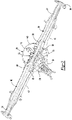
- the axle housing 30 may include a center portion 40 and at least one arm portion 42.
- the center portion 40 may be disposed proximate the center of the axle housing 30. As is best shown in Figure 2 , the center portion 40 may define an internal cavity that may at least partially receive the differential assembly 22. The internal cavity may also receive a portion of a dam 26. As is best shown in Figure 3 , a lower region of the center portion 40 may at least partially define a sump portion 50 that may contain or collect lubricant 52. Lubricant 52 in the sump portion 50 may be splashed by the differential assembly 22 when the differential assembly 22 rotates. Some splashed lubricant 52 may be captured or collected by the lubricant reservoir 28 as will be discussed in more detail below.
- the lubricant 52 which may be a liquid such as oil, may lubricate components of the axle assembly 10, such as the differential assembly 22 and various bearings.
- the level of the lubricant 52 in the arm portions 42 and the sump portion 50 is represented by the dashed lines.
- the lubricant levels are merely exemplary and may be higher or lower than what is depicted.
- center portion 40 may also include a carrier mounting surface 54.
- the carrier mounting surface 54 may face toward and may engage the differential carrier 32.
- the carrier mounting surface 54 may facilitate mounting of the differential carrier 32 to the axle housing 30.
- the carrier mounting surface 54 may have a set of holes that may be aligned with corresponding holes on the differential carrier 32. Each hole may receive a fastener, such as a bolt, that may couple the differential carrier 32 to the axle housing 30.
- one or more arm portions 42 may extend from the center portion 40.
- two arm portions 42 may extend in opposite directions from the center portion 40 and away from the differential assembly 22.
- the arm portions 42 may have similar configurations.
- the arm portions 42 may each have a hollow configuration or tubular configuration that may extend around a corresponding axle shaft 24 and may help separate or isolate the axle shaft 24 from the surrounding environment.
- An arm portion 42 or a portion thereof may be integrally formed with the center portion 40.
- an arm portion 42 may be separate from the center portion 40.
- each arm portion 42 may be attached to the center portion 40 in any suitable manner, such as by welding or with one or more fasteners.
- Each arm portion 42 may define an arm cavity 60 that may receive a corresponding axle shaft 24.
- the arm portion 42 and arm cavity 60 may be disposed above the sump portion 50 as is best shown in Figure 3 .
- the differential carrier 32 may be mounted to the center portion 40 of the axle housing 30.
- the differential carrier 32 may support components of the differential assembly 22.
- the differential carrier 32 may include a flange portion 70 and a bearing support 72.
- the flange portion 70 may facilitate mounting of the differential carrier 32 to another component of the axle assembly 10, such as the axle housing 30.
- the flange portion 70 may be disposed proximate and may engage the carrier mounting surface 54 of the axle housing 30 and may have a set of holes that may receive fasteners as previously discussed.
- the bearing support 72 may receive a bearing 80 that may rotatably support the differential assembly 22.
- the bearing 80 may have any suitable configuration.
- the bearing 80 may be a roller bearing assembly.
- two bearing supports 72 are provided with the differential carrier 32.
- the bearing supports 72 may be received inside the center portion 40 of the axle housing 30 and may be disposed proximate opposite ends of the differential assembly 22.
- the bearing support 72 may include a pair of legs 82 that extend from the differential carrier 32 toward the axle housing 30.
- a bearing cap 84 may be disposed on the bearing support 72. Only one bearing cap 84 is shown in Figure 6 for clarity.
- the bearing cap 84 may be mounted to the pair of legs 82 and may arch over the bearing 80. As such, the bearing support 72 and bearing cap 84 may cooperate to extend around and encircle the bearing 80 and may cooperate to receive and secure the bearing 80.
- the bearing support 72 and the bearing cap 84 may also extend around or encircle an axis 90 about which the differential assembly 22 may rotate.
- the bearing cap 84 may include a pair of holes 100.
- Each hole may receive a fastener 102, such as a bolt, that may couple the bearing cap 84 to the bearing support 72.
- a fastener 102 such as a bolt
- the hole 100 that is located above the axis 90 from the perspective shown in Figures 3 and 6 may be referred to as an upper hole and a hole that is located below the axis 90 may be referred to as a lower hole.
- Each fastener 102 may also be received in a corresponding hole in a leg 82 of the bearing support 72.
- the differential assembly 22 may be at least partially received inside the center portion 40 of the axle housing 30.
- the differential assembly 22 may be rotatable about the axis 90 and may transmit torque to the axle shafts 24 and wheels.
- the differential assembly 22 may be operatively connected to the axle shafts 24 and may permit the axle shafts 24 to rotate at different rotational speeds in a manner known by those skilled in the art.
- the differential assembly 22 may have a ring gear 110 that may be fixedly mounted to a case of the differential assembly 22.
- the ring gear 110 may be rotatable about the axis 90 and may splash lubricant 52 that accumulates in the sump portion 50 as it rotates.
- the ring gear 110 may have a set of teeth 112 that may be arranged around the axis 90.
- the teeth 112 may face toward lubricant reservoir 28 and may mate or mesh with the teeth of a gear portion of a drive pinion 120, which is best shown in Figures 1 and 2 . Accordingly, the differential assembly 22 may receive torque from the drive pinion 120 via the ring gear 110 and transmit torque to the axle shafts 24.
- the drive pinion 120 may operatively connect a power source to the differential assembly 22.
- the power source may be an electrical power source like an electric motor or a non-electrical power source like an internal combustion engine.
- the drive pinion 120 may transmit torque between the differential assembly 22 and the power source.
- the drive pinion 120 may be rotatable about a drive pinion axis 122, which is best shown in Figure 1 , and may be rotatably supported by the differential carrier 32.
- the axle shafts 24 may transmit torque from the differential assembly 22 to corresponding traction wheel assemblies.
- Two axle shafts 24 may be provided such that each axle shaft 24 extends through a different arm cavity 60.
- the axle shafts 24 may extend along and may be rotated about an axis, such as the axis 90.
- Each axle shaft 24 may have a first end and a second end. The first end may be operatively connected to the differential assembly 22. The second end may be disposed opposite the first end and may be operatively connected to a wheel end assembly that may have a wheel hub that may support a wheel.
- a dam 26 may be disposed in the axle housing 30 and may help capture or store a volume of lubricant 52 in the arm cavity 60 remotely from the sump portion 50.
- the dam 26 may be fixedly mounted to the axle housing 30, may be at least partially disposed in the arm portion 42, may be completely disposed below an axle shaft 24 that extends through the arm portion 42 that receives the dam 26, or combinations thereof.
- the dam 26 may cooperate with the arm cavity 60 to at least partially define an arm reservoir 130.
- the arm reservoir 130 may be configured to store a volume of lubricant 52 in the arm portion 42. Storing lubricant 52 in the arm reservoir 130 may reduce the amount of lubricant 52 in the sump portion 50.
- lubricant 52 in the arm reservoir 130 may lubricate a roller bearing assembly that may rotatably support the axle shaft 24 and that may be located near the end of the arm portion 42 that is disposed opposite the center portion 40.
- An example of a dam 26 is disclosed in U.S. Patent No. 10,167,944 , which is hereby incorporated by reference in its entirety.
- the lubricant reservoir 28 may capture lubricant 52 that is splashed by the differential assembly 22.
- the lubricant reservoir 28 may be disposed in the center portion 40 of the axle housing 30 and may be mounted on the bearing cap 84 that teeth 112 of the ring gear 110 extend toward.
- the lubricant reservoir 28 may be disposed above the sump portion 50.
- the lubricant reservoir 28 may be spaced apart from and may not engage the differential assembly 22, the axle housing 30, the differential carrier 32, or combinations thereof.
- the lubricant reservoir 28 may include a reservoir tank 140, an outlet pipe 142, and a bracket 144.
- the reservoir tank 140 may be a portion of the lubricant reservoir 28 that may capture and contain lubricant 52. As is best shown in Figure 5 , the reservoir tank 140 may be completely disposed above the axis 90. In at least one configuration, the reservoir tank 140 may include an inboard tank portion 150 and an outboard tank portion 152.
- the inboard tank portion 150 may define an opening 160 that may receive splashed lubricant 52.
- the inboard tank portion 150 may be positioned closer to the ring gear 110 than the outboard tank portion 152.
- the inboard tank portion 150 may be laterally positioned or positioned in a direction that extends along or parallel to the axis 90 between the ring gear 110 and the bearing cap 84 to which the reservoir tank 140 is mounted as is best shown in Figure 5 .
- the inboard tank portion 150 may extend above the top of the bearing cap 84 and thus may be located closer to the teeth 112 of the ring gear 110 and closer to where lubricant 52 may be flung from the ring gear 110 when it rotates.
- the inboard tank portion 150, its opening 160, or both may be at least partially defined by a front wall 170, a rear wall 172, an inboard wall 174, and outboard wall 176, and a bottom wall 178.
- the front wall 170 may face toward the differential carrier 32 and the case of the differential assembly 22.
- the front wall 170 or a portion thereof may be disposed substantially perpendicular to the axis 90 in one or more configurations.
- substantially parallel means the same as or very close to parallel and includes features or axes that are within ⁇ 2° of being parallel each other.
- the rear wall 172 may be disposed opposite the front wall 170.
- the rear wall 172 may face toward the axle housing 30 and may follow the contour or shape of the axle housing 30.
- the rear wall 172 or a portion thereof may be a curved nonplanar surface.
- the inboard wall 174 may extend from the front wall 170 to the rear wall 172 and may face toward the ring gear 110. As is best shown in Figure 7 , the inboard wall 174 or a portion thereof may be disposed below the top of the front wall 170, the top of the rear wall 172, or both, to help better capture lubricant 52 that may be flung from or splashed by the ring gear 110.
- the outboard wall 176 may be disposed opposite the inboard wall 174.
- the outboard wall 176 may extend from the front wall 170 to the rear wall 172 and may face away from the ring gear 110.
- the outboard wall 176 may have a shorter height than the inboard wall 174 and may extend upward from the outboard tank portion 152.
- the bottom wall 178 may define a bottom of the inboard tank portion 150 and the outboard tank portion 152.
- the bottom wall 178 may extend from the front wall 170 to the rear wall 172.
- the bottom wall 178 may slope upward from the inboard tank portion 150 to the outboard tank portion 152.
- the bottom wall 178 may extend from the inboard wall 174 away from the ring gear 110 such that the bottom wall 178 extends further above the axis 90 as the distance from the inboard wall 174 increases.
- the outboard tank portion 152 may cooperate with the inboard tank portion 150 to define a tank cavity that may receive and at least temporarily store lubricant 52.
- the outboard tank portion 152 may extend the tank cavity in a direction that extends laterally away from the ring gear 110 and may have a smaller volume than the inboard tank portion 150.
- the outboard tank portion 152 may extend laterally or in a direction that extends along or parallel to the axis 90 past the bearing cap 84 as is best shown in Figure 5 .
- the outboard tank portion 152 may be at least partially defined by the rear wall 172 and the bottom wall 178.
- the outboard tank portion 152 may also be at least partially defined by a frontal wall 180, and a top wall 182.
- the frontal wall 180 may face toward the bearing cap 84.
- the frontal wall 180 or a portion thereof may be disposed substantially perpendicular to the axis 90 in one or more configurations.
- the frontal wall 180 may be offset from the front wall 170 such that the frontal wall 180 may be disposed further from the axis 90 than the front wall 170 is disposed from the axis 90.
- the frontal wall 180 may extend vertically from the bottom wall 178 to the top wall 182. In at least one configuration, the frontal wall 180 or a portion thereof may be disposed substantially parallel to the front wall 170.
- the top wall 182 may be disposed above and may be spaced apart from the bottom wall 178.
- the top wall 182 may extend from the frontal wall 180 to the rear wall 172 in a generally horizontal direction.
- the top wall 182 may extend from an end of the outboard wall 176 away from the ring gear 110.
- the outlet pipe 142 may receive lubricant 52 from the lubricant reservoir 28.
- the outlet pipe 142 may be fluidly connected to the outboard tank portion 152.
- the outlet pipe 142 may route or direct lubricant 52 from the lubricant reservoir 28 to the arm portion 42 and an associated arm reservoir 130.
- the outlet pipe 142 may extend from a wall of the outboard tank portion 152, such as the bottom wall 178 or the frontal wall 180, toward the axis 90 and/or toward an arm portion 42.
- lubricant 52 that exits the outlet pipe 142 may be directed or sprayed to a side of the dam 26 that may be disposed opposite the differential assembly 22 and into an associated arm reservoir 130.
- the outlet pipe 142 or a portion thereof may slope downwardly from the lubricant reservoir 28 toward an arm portion 42 to facilitate the flow of lubricant 52 through the outlet pipe 142.
- the outlet pipe 142 may be disposed above the axle shaft 24 and the dam 26.
- the bracket 144 may facilitate mounting of the reservoir tank 140.
- the reservoir tank 140 may be mounted to the bracket 144 and the bracket 144 may be disposed on the bearing cap 84.
- the bracket 144 may include a body 190, a first flange 192, a second flange 194, a support flange 196, or combinations thereof.
- the body 190 may extend in a generally vertical direction.
- the body 190 may extend along and may engage an inboard side of the bearing cap 84 that may face toward the ring gear 110.
- the first flange 192 may be disposed proximate a top end of the body 190.
- the first flange 192 may engage a side of the bearing cap 84 that may face away from the bearing support 72 and may facilitate mounting of the bracket 144.
- the first flange 192 may define a first hole 200 that may be generally aligned with the upper hole 100 in the bearing cap 84.
- a fastener 102 may extend through the first hole 200 and the upper hole 100 to couple the bracket 144 and the bearing cap 84 to the bearing support 72.
- the outboard tank portion 152 may extend above the first flange 192.
- the second flange 194 may be spaced apart from the first flange 192.
- the second flange 194 may be disposed proximate a bottom end of the body 190.
- the second flange 194 may engage a side of the bearing cap 84 that may face away from the bearing support 72 and may facilitate mounting of the bracket 144.
- the second flange 194 may define a second hole 202 that may be generally aligned with the lower hole 100 in the bearing cap 84.
- a fastener 102 may extend through the second hole 202 and the lower hole 100 to couple the bracket 144 and the bearing cap 84 to the bearing support 72.
- the inboard tank portion 150 may be disposed below the first flange 192 and above the second flange 194.
- the support flange 196 may support the reservoir tank 140.
- the support flange 196 may extend from the body 190 and may be positioned below the first flange 192 and above the second flange 194.
- the support flange 196 may be positioned below or underneath the reservoir tank 140.
- the support flange 196 may engage the bottom wall 178 and may optionally be fastened to the bottom wall 178 of the reservoir tank 140.
- the support flange 196 may define a support flange hole 210, which is best shown in Figure 6 , through which a fastener 212 like a bolt may extend.
- the fastener 212 may be fastened to the bottom wall 178 to secure the reservoir tank 140 to the support flange 196.
- An axle assembly as described above may provide a lubricant reservoir in the center portion of the axle housing that may be installable with the differential carrier.
- the lubricant reservoir may be disposed above the sump portion and may be well-positioned to capture splashed lubricant to help reduce the lubricant level in the sump portion, thereby helping reduce churning losses or frictional drag on the differential assembly. Reducing churning losses and frictional drag may help improve the operating efficiency of the axle assembly and may reduce energy consumption.
- Providing a lubricant reservoir in the center portion of the axle housing may help reduce lubricant levels in the sump portion to a greater degree than in an axle assembly that does not have such a lubricant reservoir.
- the lubricant reservoir may also help direct lubricant to an arm reservoir more precisely, such as by using an outlet pipe, as compared to relying on splashing of lubricant to direct a sufficient amount of lubricant past a dam and into an arm portion.
Landscapes
- Engineering & Computer Science (AREA)
- General Engineering & Computer Science (AREA)
- Mechanical Engineering (AREA)
- General Details Of Gearings (AREA)
Applications Claiming Priority (1)
| Application Number | Priority Date | Filing Date | Title |
|---|---|---|---|
| IN202111029125 | 2021-06-29 |
Publications (1)
| Publication Number | Publication Date |
|---|---|
| EP4112975A1 true EP4112975A1 (de) | 2023-01-04 |
Family
ID=82403921
Family Applications (1)
| Application Number | Title | Priority Date | Filing Date |
|---|---|---|---|
| EP22181668.9A Pending EP4112975A1 (de) | 2021-06-29 | 2022-06-28 | Achsenanordnung mit einem schmiermittelreservoir |
Country Status (3)
| Country | Link |
|---|---|
| US (1) | US11732794B2 (de) |
| EP (1) | EP4112975A1 (de) |
| CN (1) | CN115539613A (de) |
Families Citing this family (2)
| Publication number | Priority date | Publication date | Assignee | Title |
|---|---|---|---|---|
| DE102013018710A1 (de) * | 2013-11-08 | 2015-05-13 | Sew-Eurodrive Gmbh & Co Kg | Getriebe mit Gehäuse |
| USD1002447S1 (en) * | 2022-03-31 | 2023-10-24 | Jiexin Shengke (Weihai) New Material Technology Co., Ltd. | Axle housing |
Citations (5)
| Publication number | Priority date | Publication date | Assignee | Title |
|---|---|---|---|---|
| DE4023354A1 (de) * | 1990-07-23 | 1992-01-30 | Daimler Benz Ag | Treibachse fuer kraftfahrzeuge |
| US5813493A (en) * | 1997-04-15 | 1998-09-29 | Dana Corporation | Lubrication fluid deflector/baffle for a motor vehicle axle assembly |
| WO2015092471A1 (en) * | 2013-12-20 | 2015-06-25 | Volvo Truck Corporation | Differential arrangement and driven axle and automotive vehicle with improved lubrication |
| US10167944B2 (en) | 2016-08-12 | 2019-01-01 | Arvinmeritor Technology, Llc | Axle assembly having a lubricant reservoir |
| WO2019177882A1 (en) * | 2018-03-14 | 2019-09-19 | Dana Heavy Vehicle Systems Group, Llc | A lubricant fluid shroud |
Family Cites Families (27)
| Publication number | Priority date | Publication date | Assignee | Title |
|---|---|---|---|---|
| DE710894C (de) | 1939-03-17 | 1941-09-23 | Rheinmetall Borsig Akt Ges | Umlaufschmierung fuer Achsgetriebe von Kraftfahrzeugen |
| US2242195A (en) | 1940-08-31 | 1941-05-13 | Gen Electric | Geared axle drive |
| DE1023354B (de) | 1954-01-27 | 1958-01-23 | Hans Maag | Fahrerschutzverkleidung fuer Motorraeder |
| US3025716A (en) | 1959-09-24 | 1962-03-20 | Gen Motors Corp | Lubricant control means |
| JPS536164Y2 (de) | 1975-12-11 | 1978-02-16 | ||
| JPS5617704A (en) | 1979-07-19 | 1981-02-19 | Toyota Motor Corp | Banjo-shaped axle casing |
| JPS5937462A (ja) | 1982-08-26 | 1984-02-29 | Nec Corp | メ−タ付警報回路 |
| US5540300A (en) | 1995-01-09 | 1996-07-30 | American Axle & Manufacturing Inc. | Drive axle assembly with lubricant cooling system |
| US6135241A (en) | 1999-02-24 | 2000-10-24 | Dana Corporation | Axle housing with a deflector |
| US6132329A (en) | 1999-07-07 | 2000-10-17 | Meritor Heavy Vehicle Systems, Llc | Axle assembly lubricant temperature reduction apparatus |
| US6866605B2 (en) | 2002-06-28 | 2005-03-15 | Caterpillar Inc | Power train assembly |
| JP2006183717A (ja) * | 2004-12-27 | 2006-07-13 | Mazda Motor Corp | ディファレンシャル装置 |
| JP5697344B2 (ja) | 2010-02-15 | 2015-04-08 | トヨタ自動車株式会社 | 差動装置 |
| JP5616837B2 (ja) | 2011-03-30 | 2014-10-29 | 株式会社クボタ | 作業車 |
| US8974342B2 (en) | 2012-05-04 | 2015-03-10 | Arvinmeritor Technology, Llc | Axle assembly having a lubricant reservoir module |
| US8858381B2 (en) | 2012-09-12 | 2014-10-14 | Arvinmeritor Technology, Llc | Axle assembly having a lubricant reservoir |
| US9267596B2 (en) | 2014-01-31 | 2016-02-23 | Arvinmeritor Technology, Llc | Axle assembly with differential lubrication |
| JP6289193B2 (ja) | 2014-03-20 | 2018-03-07 | 株式会社ニフコ | デファレンシャル装置用バッフルプレート |
| US9927020B2 (en) * | 2014-06-04 | 2018-03-27 | Arvinmeritor Technology, Llc | Axle Assembly |
| US10161502B2 (en) * | 2015-04-27 | 2018-12-25 | Arvinmeritor Technology, Llc | Axle assembly having a dam module |
| US9989139B2 (en) * | 2015-06-18 | 2018-06-05 | Arvinmeritor Technology, Llc | Axle assembly having a clutch collar actuator |
| US9816603B2 (en) | 2015-09-11 | 2017-11-14 | Arvinmeritor Technology, Llc | Axle assembly with interaxle differential lubrication |
| US9677661B2 (en) | 2015-09-14 | 2017-06-13 | Arvinmeritor Technology, Llc | Axle assembly having a ballast insert |
| US10036467B2 (en) | 2015-09-29 | 2018-07-31 | Arvinmeritor Technology, Llc | Axle assembly having a ballast insert assembly and a method of control |
| BR112018009572A2 (pt) * | 2015-11-13 | 2018-11-06 | Dana Heavy Vehicle Systems Group, Llc | conjunto de eixo |
| US9797502B2 (en) * | 2016-03-23 | 2017-10-24 | Arvinmeritor Technology, Llc | Axle assembly having a lubricant reservoir |
| EP3309428B1 (de) * | 2016-10-13 | 2019-10-02 | Dana Automocion, S.A. | In einem achsgehäuse befestigte schmiermittelflüssigkeitsablenkplatte |
-
2022
- 2022-02-16 US US17/673,320 patent/US11732794B2/en active Active
- 2022-06-13 CN CN202210736101.XA patent/CN115539613A/zh active Pending
- 2022-06-28 EP EP22181668.9A patent/EP4112975A1/de active Pending
Patent Citations (5)
| Publication number | Priority date | Publication date | Assignee | Title |
|---|---|---|---|---|
| DE4023354A1 (de) * | 1990-07-23 | 1992-01-30 | Daimler Benz Ag | Treibachse fuer kraftfahrzeuge |
| US5813493A (en) * | 1997-04-15 | 1998-09-29 | Dana Corporation | Lubrication fluid deflector/baffle for a motor vehicle axle assembly |
| WO2015092471A1 (en) * | 2013-12-20 | 2015-06-25 | Volvo Truck Corporation | Differential arrangement and driven axle and automotive vehicle with improved lubrication |
| US10167944B2 (en) | 2016-08-12 | 2019-01-01 | Arvinmeritor Technology, Llc | Axle assembly having a lubricant reservoir |
| WO2019177882A1 (en) * | 2018-03-14 | 2019-09-19 | Dana Heavy Vehicle Systems Group, Llc | A lubricant fluid shroud |
Also Published As
| Publication number | Publication date |
|---|---|
| US11732794B2 (en) | 2023-08-22 |
| US20220412450A1 (en) | 2022-12-29 |
| CN115539613A (zh) | 2022-12-30 |
Similar Documents
| Publication | Publication Date | Title |
|---|---|---|
| EP4112975A1 (de) | Achsenanordnung mit einem schmiermittelreservoir | |
| EP3296596B1 (de) | Achsenanordnung mit einem schmiermittelreservoir | |
| EP2708777B1 (de) | Achsenanordnung mit Schmiermittelreservoir | |
| EP2902663B1 (de) | Achsanordnung mit differentieller Schmierung | |
| BR102016009392A2 (pt) | Axle assembly having a barrier module | |
| AU2016210769B2 (en) | Axle assembly having a ballast insert | |
| US9309961B2 (en) | Axle assembly | |
| US6964320B2 (en) | Lubrication arrangement for final drive unit | |
| EP4303469A1 (de) | Achsanordnung mit einem damm und einem schmiermittelreservoir | |
| EP4102107A1 (de) | Achsenanordnung mit einem schmiermittelreservoir | |
| EP4332411A1 (de) | Achsanordnung mit einem schmiermitteldeflektor | |
| EP3992497A1 (de) | Achsanordnung mit variabler schmiermitteldrossel | |
| EP4034407B1 (de) | Fahrzeugradanordnung | |
| CN214928965U (zh) | 一种机动载运装备及其纵臂传动箱 |
Legal Events
| Date | Code | Title | Description |
|---|---|---|---|
| PUAI | Public reference made under article 153(3) epc to a published international application that has entered the european phase |
Free format text: ORIGINAL CODE: 0009012 |
|
| STAA | Information on the status of an ep patent application or granted ep patent |
Free format text: STATUS: THE APPLICATION HAS BEEN PUBLISHED |
|
| AK | Designated contracting states |
Kind code of ref document: A1 Designated state(s): AL AT BE BG CH CY CZ DE DK EE ES FI FR GB GR HR HU IE IS IT LI LT LU LV MC MK MT NL NO PL PT RO RS SE SI SK SM TR |
|
| STAA | Information on the status of an ep patent application or granted ep patent |
Free format text: STATUS: REQUEST FOR EXAMINATION WAS MADE |
|
| P01 | Opt-out of the competence of the unified patent court (upc) registered |
Effective date: 20230531 |
|
| 17P | Request for examination filed |
Effective date: 20230629 |
|
| RBV | Designated contracting states (corrected) |
Designated state(s): AL AT BE BG CH CY CZ DE DK EE ES FI FR GB GR HR HU IE IS IT LI LT LU LV MC MK MT NL NO PL PT RO RS SE SI SK SM TR |