EP4109794A1 - Ratenanpassungsverfahren für ldpc-code und kommunikationsvorrichtung - Google Patents
Ratenanpassungsverfahren für ldpc-code und kommunikationsvorrichtung Download PDFInfo
- Publication number
- EP4109794A1 EP4109794A1 EP21767474.6A EP21767474A EP4109794A1 EP 4109794 A1 EP4109794 A1 EP 4109794A1 EP 21767474 A EP21767474 A EP 21767474A EP 4109794 A1 EP4109794 A1 EP 4109794A1
- Authority
- EP
- European Patent Office
- Prior art keywords
- code
- check
- check bits
- bits
- mother code
- Prior art date
- Legal status (The legal status is an assumption and is not a legal conclusion. Google has not performed a legal analysis and makes no representation as to the accuracy of the status listed.)
- Pending
Links
Images


Classifications
-
- H—ELECTRICITY
- H04—ELECTRIC COMMUNICATION TECHNIQUE
- H04L—TRANSMISSION OF DIGITAL INFORMATION, e.g. TELEGRAPHIC COMMUNICATION
- H04L1/00—Arrangements for detecting or preventing errors in the information received
- H04L1/004—Arrangements for detecting or preventing errors in the information received by using forward error control
- H04L1/0056—Systems characterized by the type of code used
- H04L1/0061—Error detection codes
-
- H—ELECTRICITY
- H03—ELECTRONIC CIRCUITRY
- H03M—CODING; DECODING; CODE CONVERSION IN GENERAL
- H03M13/00—Coding, decoding or code conversion, for error detection or error correction; Coding theory basic assumptions; Coding bounds; Error probability evaluation methods; Channel models; Simulation or testing of codes
- H03M13/63—Joint error correction and other techniques
- H03M13/635—Error control coding in combination with rate matching
- H03M13/6362—Error control coding in combination with rate matching by puncturing
- H03M13/6368—Error control coding in combination with rate matching by puncturing using rate compatible puncturing or complementary puncturing
- H03M13/6393—Rate compatible low-density parity check [LDPC] codes
-
- H—ELECTRICITY
- H03—ELECTRONIC CIRCUITRY
- H03M—CODING; DECODING; CODE CONVERSION IN GENERAL
- H03M13/00—Coding, decoding or code conversion, for error detection or error correction; Coding theory basic assumptions; Coding bounds; Error probability evaluation methods; Channel models; Simulation or testing of codes
- H03M13/03—Error detection or forward error correction by redundancy in data representation, i.e. code words containing more digits than the source words
- H03M13/05—Error detection or forward error correction by redundancy in data representation, i.e. code words containing more digits than the source words using block codes, i.e. a predetermined number of check bits joined to a predetermined number of information bits
- H03M13/11—Error detection or forward error correction by redundancy in data representation, i.e. code words containing more digits than the source words using block codes, i.e. a predetermined number of check bits joined to a predetermined number of information bits using multiple parity bits
- H03M13/1102—Codes on graphs and decoding on graphs, e.g. low-density parity check [LDPC] codes
-
- H—ELECTRICITY
- H03—ELECTRONIC CIRCUITRY
- H03M—CODING; DECODING; CODE CONVERSION IN GENERAL
- H03M13/00—Coding, decoding or code conversion, for error detection or error correction; Coding theory basic assumptions; Coding bounds; Error probability evaluation methods; Channel models; Simulation or testing of codes
- H03M13/63—Joint error correction and other techniques
- H03M13/6306—Error control coding in combination with Automatic Repeat reQuest [ARQ] and diversity transmission, e.g. coding schemes for the multiple transmission of the same information or the transmission of incremental redundancy
-
- H—ELECTRICITY
- H04—ELECTRIC COMMUNICATION TECHNIQUE
- H04L—TRANSMISSION OF DIGITAL INFORMATION, e.g. TELEGRAPHIC COMMUNICATION
- H04L1/00—Arrangements for detecting or preventing errors in the information received
- H04L1/0001—Systems modifying transmission characteristics according to link quality, e.g. power backoff
- H04L1/0002—Systems modifying transmission characteristics according to link quality, e.g. power backoff by adapting the transmission rate
-
- H—ELECTRICITY
- H04—ELECTRIC COMMUNICATION TECHNIQUE
- H04L—TRANSMISSION OF DIGITAL INFORMATION, e.g. TELEGRAPHIC COMMUNICATION
- H04L1/00—Arrangements for detecting or preventing errors in the information received
- H04L1/0001—Systems modifying transmission characteristics according to link quality, e.g. power backoff
- H04L1/0009—Systems modifying transmission characteristics according to link quality, e.g. power backoff by adapting the channel coding
- H04L1/0013—Rate matching, e.g. puncturing or repetition of code symbols
-
- H—ELECTRICITY
- H04—ELECTRIC COMMUNICATION TECHNIQUE
- H04L—TRANSMISSION OF DIGITAL INFORMATION, e.g. TELEGRAPHIC COMMUNICATION
- H04L1/00—Arrangements for detecting or preventing errors in the information received
- H04L1/004—Arrangements for detecting or preventing errors in the information received by using forward error control
- H04L1/0056—Systems characterized by the type of code used
- H04L1/0057—Block codes
-
- H—ELECTRICITY
- H04—ELECTRIC COMMUNICATION TECHNIQUE
- H04L—TRANSMISSION OF DIGITAL INFORMATION, e.g. TELEGRAPHIC COMMUNICATION
- H04L1/00—Arrangements for detecting or preventing errors in the information received
- H04L1/004—Arrangements for detecting or preventing errors in the information received by using forward error control
- H04L1/0056—Systems characterized by the type of code used
- H04L1/0067—Rate matching
- H04L1/0068—Rate matching by puncturing
- H04L1/0069—Puncturing patterns
-
- H—ELECTRICITY
- H04—ELECTRIC COMMUNICATION TECHNIQUE
- H04L—TRANSMISSION OF DIGITAL INFORMATION, e.g. TELEGRAPHIC COMMUNICATION
- H04L1/00—Arrangements for detecting or preventing errors in the information received
- H04L1/12—Arrangements for detecting or preventing errors in the information received by using return channel
- H04L1/16—Arrangements for detecting or preventing errors in the information received by using return channel in which the return channel carries supervisory signals, e.g. repetition request signals
- H04L1/18—Automatic repetition systems, e.g. Van Duuren systems
- H04L1/1867—Arrangements specially adapted for the transmitter end
- H04L1/1893—Physical mapping arrangements
Definitions
- the foregoing coding scheme used in the current WLAN standard cannot meet a requirement of continuously increasing redundant bits through retransmission in the IR-HARQ mechanism to reduce a channel coding rate and improve decoding performance.
- This application provides an LDPC code rate matching method and a communication apparatus, to improve decoding performance.
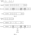
- the transmit end performs rate matching on the LDPC codeword based on the priority order of puncturing the check bits of the mother code of the LDPC code during rate matching.
- a check bit with a high priority is a sensitive bit that is easily affected by noise, and may affect an iteration process of a variable node and a check node in an iterative decoding process. Therefore, the check bits of the LDPC codeword are punctured based on the priority order, and the check bit with high sensitivity may be preferentially punctured. In this way, incorrect transfer caused by an error of these check bits in an iterative decoding process is avoided, impact on another variable node or check node is reduced. This can improve puncturing performance, and improve decoding performance.
- the transmit end punctures an LDPC codeword with a low code rate based on the priority order of the check bits of the mother code of the LDPC code, to obtain an LDPC codeword that is compatible with the low code rate and that has a higher code rate.
- the transmit end punctures a check bit corresponding to a puncturing position of an LDPC codeword with a high code rate based on the priority order of the check bits of the mother code, to obtain an LDPC codeword with a low code rate, and may obtain more LDPC codewords with low code rates. Therefore, the technical solutions of this application are also applicable to an enhanced link adaptation scenario. Two communication parties may select an appropriate code rate for communication based on a link status, to select a code rate at a finer granularity.
- the priority order indicates an order of priorities of columns corresponding to the check bits in a check matrix of the mother code.
- Each column corresponding to a check bit in the check matrix of the mother code is corresponding to z check bits of the mother code.
- z N/n
- N is a code length of the mother code
- n indicates a total quantity of columns included in the check matrix of the mother code.
- the code length of the mother code is 648
- a code rate is 1/2
- priorities of the columns corresponding to the check bits in the check matrix of the mother code are sorted in descending order as follows: 21, 15, 22, 23, 18, 19, 14, 24, 20, 16, 17, and 13, where each element a in the sorting indicates an a th column of the check matrix of the mother code.
- m columns with highest priorities in the check matrix of the mother code indicates that in all columns of the check matrix of the mother code, a priority of a column with a lowest priority in the m columns is higher than a priority of a column with a highest priority in remaining columns other than the m columns in the check matrix.
- this application provides an LDPC code decoding method.
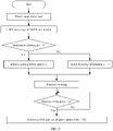
- the method includes: A receive end receives a first channel receiving sequence.
- the receive end pads, with zeros based on a priority order of check bits of a mother code of an LDPC code, corresponding puncturing positions of a first LLR sequence corresponding to the first channel receiving sequence, and decodes a first LLR sequence obtained through zero-padding.
- the corresponding puncturing positions of the first LLR sequence are positions of check bits that are punctured in a rate matching process in an LDPC codeword corresponding to the first channel receiving sequence.
- the receive end requests a transmit end to perform retransmission if a system bit of the LDPC codeword fails to be obtained through decoding.
- the receive end when the receive end successfully decodes the system bit of the LDPC code, the receive end outputs a decoding result.
- the priority order indicates sorting of priorities of columns corresponding to the check bits in a check matrix of the mother code of the LDPC.
- Each column corresponding to a check bit in the check matrix is corresponding to z codeword bits of the mother code.
- z N/n
- N indicates a code length of the mother code
- n indicates a total quantity of columns included in the check matrix of the mother code
- N and n are integers.
- Each element a in the sorting indicates an a th column of the check matrix.
- priorities of the z codeword bits corresponding to each column corresponding to the check bit in the check matrix of the mother code are the same.
- the check bit that is punctured during rate matching process in the LDPC codeword corresponding to the first channel receive sequence meets one of the following cases:
- the receive end pads with zeros based on the priority order of the check bits of the LDPC code, corresponding puncturing positions in a second LLR sequence corresponding to the second channel receiving sequence, and decodes a combined sequence of a second LLR sequence obtained through zero-padding and the first LLR sequence obtained through zero-padding.
- a set including puncturing positions that need to be padded with zeros in the second LLR sequence is a proper subset of a set including puncturing positions that need to be padded with zeros in the first LLR sequence.
- the puncturing positions that need to be padded with zeros in the second LLR sequence are first several puncturing positions that need to be padded with zeros in the first LLR sequence in ascending order of priorities.
- the puncturing positions that need to be padded with zeros in the second LLR sequence are the first several puncturing positions that need to be padded with zeros in ascending order of priorities in the first LLR sequence. It indicates that the set of puncturing positions that need to be padded with zeros in the first LLR sequence completely includes the set of the puncturing positions that need to be padded with zeros in the second LLR sequence. In addition, the puncturing positions that need to be padded with zeros in the second LLR sequence are the first several puncturing positions sorted in ascending order of the puncturing positions that need to be padded with zeros in the first LLR sequence.
- the set of puncturing positions that need to be padded with zeros in the first LLR sequence is ⁇ n 1 , n 2 , ..., n T ⁇ .
- the puncturing positions in the set are arranged in descending order of priorities, the puncturing positions that need to be padded with zeros in the second LLR column may be several puncturing positions in back-to-front order in the set ⁇ n 1 , n 2 , ..., n T ⁇ .
- the puncturing positions that need to be padded with zeros in the second LLR sequence are n T and n T-1 .
- this application provides a communication apparatus.
- the communication apparatus includes an interface circuit and a processor.
- the interface circuit is configured to receive computer code or instructions, and transmit the computer code or the instructions to the processor.
- the processor runs the computer code or the instructions, and the method in the second aspect or any implementation of the second aspect is implemented.
- this application provides a computer program product.
- the computer program product includes computer program code.
- the computer program code is run on a computer, the method according to any one of the first aspect or the possible implementations of the first aspect is implemented.
- a low-density parity check (low-density parity check, LDPC) code is a most mature and widely applied channel coding scheme.
- the LDPC code has performance close to a Shannon limit, and has many advantages, for example, good bit error performance without deep interleaving, good frame error rate performance, and a decoding delay because parallel decoding is supported. Therefore, IEEE 802.11n, 802.11ac, 802.11ax, and other protocols propose that the LDPC code be used as a standard channel coding scheme for a wireless local area network (wireless local area network, WLAN).
- WLAN wireless local area network
- the receive end pads, with zeros based on the priority order of the check bits of the mother code, corresponding positions in the check bit part of the channel receiving sequence, and then decodes an LLR sequence corresponding to the channel receiving sequence obtained through zero-padding.
- the receive end may learn, based on the priority order and the quantity N p of to-be-punctured bits, bit positions corresponding to N p ⁇ check bits with highest priorities, and the receive end pads the positions corresponding to the N p ⁇ check bits with zeros.
- positions of the check bits punctured by the transmit end during rate matching is the positions that need to be padded with zeros by the receive end before decoding.
- Each element a in the foregoing priority order indicates an a th column of the check matrix.
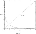
- a check bit at a bit position with low confidence is preferentially punctured, because the check bit provides less valid information for another system bit.
- puncturing the check bit can further ensure recoverability of a system bit, especially when a large quantity of bits need to be punctured.
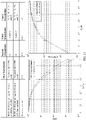
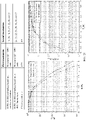
- columns related to the sorting in the table 1 include a 13 th column to a 24 th column of the check matrix. This is because the 13 th column to the 24 th column of the check matrix whose code rate is 1/2 and whose code length is 1944 are corresponding to a check part of the check matrix. Codeword bits corresponding to the part of columns are all check bits generated through encoding.
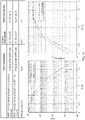
- a priority order of puncturing, during rate matching, columns corresponding to check bits in the check matrix of the LDPC code whose code rate is 1/2 and whose code length is 1296 is sorted in descending order as the following sorting 3: Sorting 3: 20, 15, 21, 14, 19, 23, 16, 24, 18, 22, 17, and 13.
- Each element a in the foregoing priority order indicates an a th column of the check matrix.
- the table 3 shows a priority sorting of check bits in a 13 th column to a 24 th column of the check matrix of the LDPC code whose code length is 1/2 and whose code length is 1296.
- the sorting 5 is represented based on a column index range, 1 to 24, of the check matrix. If a column index of the check matrix starts from 0, a priority order of puncturing, during rate matching, columns corresponding to check bits in the check matrix of the LDPC code whose code rate is 1/2 and whose code length is 1296 is sorted in descending order as the following sorting 6: Sorting 6: 20, 14, 21, 22, 17, 18, 13, 23, 19, 15, 16, and 12.
- Absolute values of an LLR of check bits in the check matrix corresponding to the LDPC code whose code rate is 1/2 and whose code length is 648 and a reliability sorting of the check bits may be shown in a table 4.
- the table 4 shows a priority sorting of check bits in a 13 th column to a 24 th column of the check matrix of the LDPC code whose code length is 1/2 and whose code length is 1296.
- Each column of the check matrix of the LDPC code whose code rate is 1/2 and whose code length is 648 is corresponding to 27 check bits of the mother code.
- Priorities of puncturing check bits that belong to a same column of the check matrix are the same.
- the 21 th column with a highest priority is corresponding to 27 check bits of the mother code, and priorities of the 27 check bits are the same.
- the transmit end needs to puncture t check bits in the 21 th column, and t ⁇ 27, the t check bits may be randomly selected from 27 check bits in the 21 th column.
- Other columns in the table 4 are similar, and details are not described again.
- the transmit end uses a check matrix corresponding to an LDPC code whose code rate is 1/2 and whose code length is 1296, the length of the first LDPC codeword obtained through encoding is 1296.
- the transmit end uses a check matrix corresponding to an LDPC code whose code rate is 1/2 and whose code length is 648, the length of the first LDPC codeword obtained through encoding is 648.
- the transmit end performs rate matching on the first LDPC codeword based on a priority order of check bits of a mother code, to obtain a second LDPC codeword.
- the receive end pads with zeros based on the priority order of the check bits of the LDPC code whose code rate is 1/2 and whose code length is N, corresponding puncturing positions of a first LLR sequence corresponding to the first channel receiving sequence, and then decodes a first LLR sequence obtained through zero-padding.
- both the receive end and the transmit end store priority information of check bits of LDPC codes that have different code lengths and whose code rates are 1/2, the receive end may learn of positions of punctured check bits based on a current code rate and a current code length. Therefore, the receive end pads, with zeros, the positions of these punctured check bits before performing decoding.
- the receive end When the receive end successfully decodes all the system bits, the receive end outputs a decoding result.
- the retransmission indication information indicates the transmit end to retransmit the LDPC codeword.
- the retransmission indication information may further indicate a part that is not correctly received.
- the part that is not correctly received may be a codeword (codeword) or a media access control protocol data unit (media access control protocol data unit, MPDU) MPDU, depending on a specific configuration.
- the second LDPC code with the second code rate is not successfully decoded by the receive end.
- a code rate is usually reduced, to increase a probability of successful decoding by the receive end. Therefore, in an example, a code rate (namely, the third code rate) of the third LDPC code is lower than the second code rate.
- a puncturing pattern corresponding to a high code rate is compatible with a puncturing pattern corresponding to a low code rate.
- the puncturing pattern of the high code rate includes the puncturing pattern of the low code rate.
- a set of puncturing positions of the low code rate includes a set of puncturing positions of the high code rate.
- the transmit end first sends the second LDPC codeword with a higher code rate. If the receive end does not correctly decode all the system bits of the second LDPC codeword, the transmit end may send t more punctured check bits.
- the transmit end may send only punctured check bits.
- the t check bits may be first t check bits with highest reliability in all the punctured check bits of the first LDPC codeword.
- a priority order of puncturing check bits of an LDPC code whose code length is L is shown as follows: ⁇ n 1 , n 2 , ..., n k , ... ⁇ , where n i indicates a position of a punctured check bit, and both n i and k are integers.
- a value range of t may be (1, m), where m is an integer.
- the transmit end may send a part of punctured check bits and system bits. This is not limited in this specification.
- the combined sequence is obtained by combining the second LLR sequence that is padded with zeros and the first LLR sequence that is padded with zeros. Specifically, the second LLR sequence that is padded with zeros and the first LLR sequence that is padded with zeros are combined bitwise. LLR values at a same bit position in the second LLR sequence that is padded with zeros and the first LLR sequence that is padded with zeros are combined, and LLR values at different bit positions are retained.
- the receive end still fails to obtain, based on the combination sequence, the system bits through decoding.
- the receive end may request the transmit end to perform next retransmission, until the receive end successfully obtains the system bits through decoding, or until a specified maximum quantity of retransmissions is reached, then the receive end determines that decoding fails, as described in step 610.
- Initial IR-HARQ transmission is performed, and the transmit end may determine, based on a code rate required for the initial IR-HARQ transmission, a quantity L of check bits that need to be punctured.
- the transmit end selects, based on the quantity L of check bits that need to be punctured and the priority order of the check bits, first L check bits with highest priorities, and records respective positions of the L check bits.
- the transmit end punctures the L check bits of an output LDPC codeword and then sends the LDPC codeword.
- the L check bits punctured in the initial transmission are ⁇ n 1 , n 2 , ..., n T ⁇ , where the sorting in descending order of priorities.
- an LDPC code with a high code rate is obtained through puncturing, for example, the code rate is 5/6.
- the receive end determines, based on a currently used code length, the code rate, and the corresponding quantity L of to-be-punctured bits of the LDPC code and based on the priority order of the check bits, the respective positions (namely, indexes) of the L check bits with highest priorities. After padding the positions corresponding to the L check bits with zeros, the receive end decodes the LDPC code.
- the transmit end may select the t 1 check bits from ⁇ n 1 , n 2 , ..., n T ⁇ in back-to-front order.
- the selected t 1 check bits should be ⁇ n T , n T-1 , ..., n W ⁇ , where there are a total of t 1 indexes from T to W.
- next retransmission is performed.
- the rest may be deduced by analogy until the transmit end sends all check bits in ⁇ n 1 , n 2 , ..., n T ⁇ . In this case, if the receive end still cannot correctly restore the system bits, it indicates that the data packet fails to be transmitted, and the transmission ends.
- the transmit end preferentially punctures a check bit with a high priority, that is, preferentially punctures a check bit with high sensitivity and low reliability.
- a check bit with a low priority in punctured check bits is preferentially sent.
- the transmit end follows such a principle, so that a probability of successful decoding by the receive end can be increased.
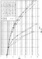
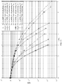
- FIG. 10 to FIG. 23 are diagrams of comparisons between BER performance curves of LDPC codes with different quantities of to-be-punctured bits and BER performance curves of conventional puncturing solutions according to this application.
- performance evaluation parameters considered in FIG. 10 to FIG. 23 are mainly a frame error rate (frame error rate, FER) and throughput (throughput).
- Throughput (Quantity of correctly received frames ⁇ k)/Total quantity of sent bits.
- k is a quantity of information bits of each frame.
- E s /N 0 in each figure indicates a symbol signal-to-noise ratio
- E b /N 0 indicates a bit error rate.
- An LDPC code in a conventional method is a QC-LDPC code whose code length is 1944 or 972 in an 802.11ac standard.
- the reliability based puncturing indicates performance of a puncturing solution in this application
- the standard-based puncturing indicates performance of a conventional puncturing solution.
- a number in a bracket following “puncturing” indicates a quantity of to-be-punctured bits, which are puncturing two columns, four columns, six columns, eight columns, and nine columns in the table 2.
- FIG. 13 is an application example of a puncturing solution of an LDPC code whose maximum quantity of retransmissions is 3 and whose code length is 1944 in the IR-HARQ mechanism.
- FIG. 17 is still yet another application example of a puncturing solution of an LDPC code whose maximum quantity of retransmissions is 3 and whose code length is 1944 in the IR-HARQ mechanism.
- FIG. 18 is a further application example of a puncturing solution of an LDPC code whose maximum quantity of retransmissions is 3 and whose code length is 1944 in the IR-HARQ mechanism.
- FIG. 22 is still another application example of a puncturing solution of an LDPC code whose maximum quantity of retransmissions is 1 and whose code length is 1944 in the IR-HARQ mechanism.
- the code length of the mother code is 1944
- a code rate is 1/2
- priorities of the columns corresponding to the check bits in the check matrix of the mother code are sorted in descending order as follows: 19, 20, 18, 21, 17, 22, 16, 23, 15, 24, 14, and 13, where each element a in the sorting indicates an a th column of the check matrix.
- the code length of the mother code is 1296
- a code rate is 1/2
- priorities of the columns corresponding to the check bits in the check matrix of the mother code are sorted in descending order as follows: 20, 15, 21, 14, 19, 23, 16, 24, 18, 22, 17, and 13, where each element a in the sorting indicates an a th column of the check matrix.
- the processing unit 610 is configured to puncture, based on the priority order, z check bits corresponding to each of m columns with highest priorities in the check matrix of the mother code, where m ⁇ 1 and m is an integer.
- the transceiver unit 620 is further configured to send the third codeword.
- the communication apparatus 600 is the transmit end in the foregoing method embodiments, and the communication apparatus 600 may have any function of the transmit end in the method embodiments.
- the processing unit 610 may be a processor.
- the transceiver unit 620 may be a transceiver.
- the transceiver may specifically include a receiver and a transmitter. The receiver is configured to perform a receiving function, and the transmitter is configured to perform a transmitting function.
- the communication apparatus 600 may be a circuit system in a transmit device.
- the processing unit 610 may be a chip, a logic circuit, an integrated circuit, a processing circuit, a system on chip (system on chip, SoC) chip, or the like.
- the transceiver unit 620 may be a communication interface.
- the communication interface may be an interface circuit, an input/output interface, or the like.
- the communication apparatus 600 may be an encoder in a transmit device.
- the processing unit 610 may further include one or more memories.
- the one or more processors are connected to the one or more memories by using a circuit/wire.
- the one or more processors may read a computer program or instructions stored in the one or more memories, so that operations and/or processing performed by the transmit end in the method embodiments of this application are performed.
- the processing unit 610 is a processor
- the transceiver unit 620 may be an interface circuit.
- the interface circuit is configured to receive computer code or instructions, and transmit the computer code or the instructions to the processor.
- the processor executes the computer code or the instructions, so that operations and/or processing performed by the transmit end in the method embodiments of this application are/is performed.
- the transceiver unit 810 is configured to receive a first channel receiving sequence.
- the processing unit 820 is configured to: pad, with zeros based on a priority order of check bits of a mother code of an LDPC code, corresponding puncturing positions of a first LLR sequence corresponding to the first channel receiving sequence, and decode a first LLR sequence obtained through zero-padding.
- the corresponding puncturing positions of the first LLR sequence are positions of check bits that are punctured in a rate matching process in an LDPC codeword corresponding to the first channel receiving sequence.
- the priority order indicates sorting of priorities of columns corresponding to the check bits in a check matrix of the mother code of the LDPC.
- Each column corresponding to a check bit in the check matrix is corresponding to z codeword bits of the mother code.
- z N/n
- N indicates a code length of the LDPC code
- n indicates a total quantity of columns included in the check matrix of the mother code
- N and n are integers.
- the length of the mother code is 1944
- a code rate is 1/2
- priorities of the columns corresponding to the check bits in the check matrix of the mother code are sorted in descending order as follows: 19, 20, 18, 21, 17, 22, 16, 23, 15, 24, 14, and 13.
- Each element a in the sorting indicates an a th column of the check matrix.
- Each element a in the sorting indicates an a th column of the check matrix.
- priorities of the z codeword bits corresponding to each column corresponding to the check bit in the check matrix of the mother code are the same.
- the punctured check bit is z check bits corresponding to each of m columns with highest priorities in the check matrix, where m ⁇ 1, and m is an integer.
- the transceiver unit 820 is further configured to:
- the processing unit 810 is further configured to: pad, with zeros based on the priority order of the check bits of the mother code, corresponding puncturing positions in a second LLR sequence corresponding to the second channel receiving sequence, and decode a combined sequence of a second LLR sequence obtained through zero-padding and the first LLR sequence obtained through zero-padding.
- a set including puncturing positions that need to be padded with zeros in the second LLR sequence is a proper subset of a set including puncturing positions that need to be padded with zeros in the first LLR sequence.
- the transceiver unit 820 may alternatively be replaced with a sending unit or a receiving unit.
- the transceiver unit 820 may be replaced with the sending unit.
- the transceiver unit 820 may be replaced with the receiving unit.
- the communication apparatus 800 may be a receive end, or the communication apparatus 800 may be a component, a module, or the like that is inside the receive end and that has a function of implementing the method embodiments.
- the communication apparatus 800 is the receive end in the foregoing method embodiments, and the communication apparatus 800 may have any function of the receive device in the method embodiments.
- the processing unit 810 may be a processor
- the transceiver unit 820 may be a transceiver.
- the transceiver may specifically include a receiver and a transmitter. The receiver is configured to perform a receiving function, and the transmitter is configured to perform a transmitting function.
- the communication apparatus 800 may be a circuit system of the receive end.
- the processing unit 810 may be a chip, a logic circuit, an integrated circuit, a processing circuit, a SoC chip, or the like.
- the transceiver unit 820 may be a communication interface.
- the communication interface may be an interface circuit, an input/output interface, or the like.
- a function of the processing unit 810 may be implemented by hardware, or may be implemented by hardware by executing corresponding software.
- the processing unit 810 may include one or more processors.
- the one or more processors are configured to read and execute a computer program or instructions stored in a memory, so that operations and/or processing performed by the receive end in the method embodiments are performed.
- the memory is located outside the one or more processors.
- the processing unit 810 may further include one or more memories.
- the one or more processors are connected to the one or more memories by using a circuit/wire.
- the one or more processors may read a computer program or instructions stored in the one or more memories, so that operations and/or processing performed by the receive end in the method embodiments of this application are performed.
- this application further provides a computer-readable storage medium.
- the computer-readable storage medium stores computer instructions. When the computer instructions are run on a computer, operations and/or processing performed by a transmit end in the LDPC code rate matching method provided in this application are/is performed.
- This application further provides a computer-readable storage medium.
- the computer-readable storage medium stores computer instructions.
- the computer instructions When the computer instructions are run on a computer, the computer is enabled to perform operations and/or processing performed by a receive end in the LDPC code decoding method provided in this application.
- the application further provides a computer program product.
- the computer program product includes computer code or instructions.
- the computer code or the instructions is run or are run on a computer, the LDPC code rate matching method in the method embodiments of this application is implemented.
- This application further provides a communication apparatus, including a processor and an interface circuit.
- the interface circuit is configured to receive computer code or instructions, and transmit the computer code or instructions to the processor, and the processor is configured to run the computer code or instructions, so that operations and/or processing performed by a receive end in the LDPC code decoding method provided in this application is performed.
- the chip includes one or more processors.
- the one or more processors are configured to execute a computer program stored in a memory, to perform operations and/or processing performed by a transmit device in any method embodiment.
- the memory is disposed independent of the chip.
- the chip includes one or more processors.
- the one or more processors are configured to execute a computer program stored in a memory, to perform operations and/or processing performed by a receive device in any method embodiment.
- the memory is disposed independent of the chip.
- one of the transmit end and the receive end is a network device (for example, a base station), and the other is a terminal device.
- a network device for example, a base station
- the other is a terminal device.
- the processor in this embodiment of this application may be an integrated circuit chip, and has a signal processing capability.
- steps in the foregoing method embodiments can be implemented by using a hardware integrated logical circuit in the processor, or by using instructions in a form of software.
- the processor may be a general-purpose processor, a digital signal processor (digital signal processor, DSP), an application-specific integrated circuit (application specific integrated circuit, ASIC), a field programmable gate array (field programmable gate array, FPGA) or another programmable logic device, a discrete gate or a transistor logic device, or a discrete hardware component.
- the general-purpose processor may be a microprocessor, or the processor may be any conventional processor or the like.
- a software module may be located in a mature storage medium in the art, such as a random access memory, a flash memory, a read-only memory, a programmable read-only memory, an electrically erasable programmable memory, or a register.
- the storage medium is located in the memory, and a processor reads information in the memory and completes the steps in the foregoing methods in combination with hardware of the processor.
- RAMs in many forms are available, for example, a static random access memory (static RAM, SRAM), a dynamic random access memory (dynamic RAM, DRAM), a synchronous dynamic random access memory (synchronous DRAM, SDRAM), a double data rate synchronous dynamic random access memory (double data rate SDRAM, DDR SDRAM), an enhanced synchronous dynamic random access memory (enhanced SDRAM, ESDRAM), a synchlink dynamic random access memory (synchlink DRAM, SLDRAM), and a direct rambus random access memory (direct rambus RAM, DRRAM).
- static random access memory static random access memory
- DRAM dynamic random access memory
- DRAM dynamic random access memory
- SDRAM synchronous dynamic random access memory
- double data rate SDRAM double data rate SDRAM
- DDR SDRAM double data rate SDRAM
- ESDRAM enhanced synchronous dynamic random access memory
- synchlink dynamic random access memory synchlink dynamic random access memory
- direct rambus RAM direct rambus RAM
- a component may be, but is not limited to, a process that runs on a processor, a processor, an object, an executable file, an execution thread, a program, and/or a computer.
- a computing device and an application that runs on the computing device may be components.
- One or more components may reside within the process and/or the execution thread.
- the components may be located on one computer and/or distributed between two or more computers.
- these components may be executed from various computer-readable media that store various data structures.
- the components may communicate by using a local and/or remote process based on a signal having one or more data packets (for example, data from two components interacting with another component in a local system, a distributed system, and/or another network, such as the Internet for interacting with another system by using the signal).
- a signal having one or more data packets (for example, data from two components interacting with another component in a local system, a distributed system, and/or another network, such as the Internet for interacting with another system by using the signal).
- the disclosed system, apparatus, and method may be implemented in other manners.
- the described apparatus embodiment is merely an example.
- division into the units is merely logical function division and may be other division during actual implementation.
- a plurality of units or components may be combined or integrated into another system, or some features may be ignored or not performed.
- the displayed or discussed mutual couplings or direct couplings or communication connections may be implemented by using some interfaces.
- the indirect couplings or communication connections between the apparatuses or units may be implemented in electronic, mechanical, or other forms.
- the functions When the functions are implemented in the form of a software functional unit and sold or used as an independent product, the functions may be stored in a computer-readable storage medium.
- the computer software product is stored in a storage medium, and includes several instructions for instructing a computer device (which may be a personal computer, a server, a network device, or the like) to perform all or some of the steps of the methods described in embodiments of this application.
- the foregoing storage medium includes any medium that can store program code, such as a removable hard disk, a read-only memory, a random access memory, a magnetic disk, or an optical disc.
Landscapes
- Engineering & Computer Science (AREA)
- Computer Networks & Wireless Communication (AREA)
- Signal Processing (AREA)
- Physics & Mathematics (AREA)
- Probability & Statistics with Applications (AREA)
- Theoretical Computer Science (AREA)
- Quality & Reliability (AREA)
- Error Detection And Correction (AREA)
Applications Claiming Priority (2)
| Application Number | Priority Date | Filing Date | Title |
|---|---|---|---|
| CN202010177240.4A CN113395132A (zh) | 2020-03-13 | 2020-03-13 | Ldpc码的速率匹配的方法和通信装置 |
| PCT/CN2021/080532 WO2021180217A1 (zh) | 2020-03-13 | 2021-03-12 | Ldpc码的速率匹配的方法和通信装置 |
Publications (2)
| Publication Number | Publication Date |
|---|---|
| EP4109794A1 true EP4109794A1 (de) | 2022-12-28 |
| EP4109794A4 EP4109794A4 (de) | 2023-08-02 |
Family
ID=77616351
Family Applications (1)
| Application Number | Title | Priority Date | Filing Date |
|---|---|---|---|
| EP21767474.6A Pending EP4109794A4 (de) | 2020-03-13 | 2021-03-12 | Ratenanpassungsverfahren für ldpc-code und kommunikationsvorrichtung |
Country Status (3)
| Country | Link |
|---|---|
| EP (1) | EP4109794A4 (de) |
| CN (1) | CN113395132A (de) |
| WO (1) | WO2021180217A1 (de) |
Families Citing this family (4)
| Publication number | Priority date | Publication date | Assignee | Title |
|---|---|---|---|---|
| CN115811379A (zh) * | 2021-09-15 | 2023-03-17 | 华为技术有限公司 | 编码方法、译码方法以及相关装置 |
| CN117318881A (zh) * | 2022-06-24 | 2023-12-29 | 华为技术有限公司 | 编码方法、译码方法及装置 |
| CN115425988B (zh) * | 2022-07-29 | 2024-02-09 | 北京融为科技有限公司 | 一种高速ldpc全模式列变换方法 |
| CN117675093A (zh) * | 2022-08-25 | 2024-03-08 | 华为技术有限公司 | 速率匹配的方法和通信装置 |
Family Cites Families (11)
| Publication number | Priority date | Publication date | Assignee | Title |
|---|---|---|---|---|
| CN101771499B (zh) * | 2009-01-05 | 2012-08-08 | 华为技术有限公司 | 打孔比特集合查找方法、装置以及打孔的方法 |
| KR101791477B1 (ko) * | 2011-10-10 | 2017-10-30 | 삼성전자주식회사 | 통신/방송 시스템에서 데이터 송수신 장치 및 방법 |
| CN106464421B (zh) * | 2014-04-30 | 2019-10-18 | 华为技术有限公司 | 一种数据发送方法和装置 |
| US9602243B2 (en) * | 2014-08-26 | 2017-03-21 | Electronics And Telecommunications Research Institute | Low density parity check encoder, and low density parity check encoding method using the same |
| CN106656409B (zh) * | 2015-10-30 | 2020-02-14 | 华为技术有限公司 | 一种校验码穿孔和解穿孔方法及装置 |
| CN105490684B (zh) * | 2015-11-30 | 2019-06-04 | 华侨大学 | 一种有限长ldpc码的打孔算法 |
| CN108432167B (zh) * | 2016-01-14 | 2021-07-30 | 苹果公司 | 对消息进行编码解码的装置、系统和计算机可读介质 |
| WO2018032518A1 (zh) * | 2016-08-19 | 2018-02-22 | 华为技术有限公司 | 一种ldpc码的基矩阵生成方法、编译码方法及设备 |
| CN108206722B (zh) * | 2016-12-16 | 2020-04-03 | 普天信息技术有限公司 | 高码率数据发送方法和装置 |
| CN107294543B (zh) * | 2017-06-19 | 2020-01-03 | 电子科技大学 | 一种用于生成rc-ldpc码校验矩阵的方法 |
| CN107181576B (zh) * | 2017-07-07 | 2020-02-21 | 西安电子科技大学 | 一种适用于5g中ldpc码的ir-harq传输方法 |
-
2020
- 2020-03-13 CN CN202010177240.4A patent/CN113395132A/zh active Pending
-
2021
- 2021-03-12 EP EP21767474.6A patent/EP4109794A4/de active Pending
- 2021-03-12 WO PCT/CN2021/080532 patent/WO2021180217A1/zh unknown
Also Published As
| Publication number | Publication date |
|---|---|
| WO2021180217A1 (zh) | 2021-09-16 |
| CN113395132A (zh) | 2021-09-14 |
| EP4109794A4 (de) | 2023-08-02 |
Similar Documents
| Publication | Publication Date | Title |
|---|---|---|
| EP4109794A1 (de) | Ratenanpassungsverfahren für ldpc-code und kommunikationsvorrichtung | |
| EP3335321B1 (de) | Ratenkompatible polar codes | |
| US20190222229A1 (en) | Methods and systems for encoding and decoding for ldpc codes | |
| Hamidi-Sepehr et al. | Analysis of 5G LDPC codes rate-matching design | |
| US20220158758A1 (en) | Data encoding method and device, storage medium, and processor | |
| US20200106459A1 (en) | Method and apparatus for wirelessly communicating over a noisy channel with a variable codeword length polar code to improve transmission capacity | |
| US11664928B2 (en) | Multi-label offset lifting method | |
| US11881870B2 (en) | LDPC code encoding method and communication apparatus | |
| US11616598B2 (en) | Puncturing and retransmission techniques for encoded transmissions | |
| US20240030941A1 (en) | Encoding and decoding method and apparatus | |
| EP4373019A2 (de) | Hochratige lange ldpc-codes | |
| US10498496B2 (en) | Retransmission technique | |
| CN115996061A (zh) | 使用行正交结构的ldpc码传输方法以及用于此的设备 | |
| KR20210111811A (ko) | 무선 네트워크에서의 데이터 재송신 | |
| CN111357218A (zh) | 用于在通信或广播系统中对信道进行编码和解码的方法和设备 | |
| US20190020357A1 (en) | Device and Method of Decoding a Raptor Code | |
| EP4156522A1 (de) | Ratenanpassungsverfahren für ldpc-code und kommunikationsvorrichtung | |
| US11876538B2 (en) | Convolutional code rate matching method and wireless communication apparatus | |
| WO2023273995A1 (zh) | 数据处理方法及装置 | |
| EP3641172B1 (de) | Informationsverarbeitungsverfahren und kommunikationsvorrichtung | |
| EP3301814A1 (de) | Message passing decodierer zur gemeinsamen decodierung von ldpc codes und faltungs- oder turbocodes | |
| WO2024041194A1 (zh) | 速率匹配的方法和通信装置 | |
| WO2024067350A1 (zh) | 级联码的编码和译码的方法以及通信装置 | |
| US11088706B2 (en) | Information processing method, apparatus, and communications device | |
| US20230208555A1 (en) | Permutated extension and shortened low density parity check codes for hybrid automatic repeat request |
Legal Events
| Date | Code | Title | Description |
|---|---|---|---|
| STAA | Information on the status of an ep patent application or granted ep patent |
Free format text: STATUS: THE INTERNATIONAL PUBLICATION HAS BEEN MADE |
|
| PUAI | Public reference made under article 153(3) epc to a published international application that has entered the european phase |
Free format text: ORIGINAL CODE: 0009012 |
|
| STAA | Information on the status of an ep patent application or granted ep patent |
Free format text: STATUS: REQUEST FOR EXAMINATION WAS MADE |
|
| 17P | Request for examination filed |
Effective date: 20220921 |
|
| AK | Designated contracting states |
Kind code of ref document: A1 Designated state(s): AL AT BE BG CH CY CZ DE DK EE ES FI FR GB GR HR HU IE IS IT LI LT LU LV MC MK MT NL NO PL PT RO RS SE SI SK SM TR |
|
| DAV | Request for validation of the european patent (deleted) | ||
| DAX | Request for extension of the european patent (deleted) | ||
| A4 | Supplementary search report drawn up and despatched |
Effective date: 20230704 |
|
| RIC1 | Information provided on ipc code assigned before grant |
Ipc: H04L 1/1867 20230101ALI20230628BHEP Ipc: H03M 13/00 20060101ALI20230628BHEP Ipc: H04L 1/00 20060101AFI20230628BHEP |