EP4108359B1 - Blaskopfarretierungsystem und verwendungsverfahren dafür - Google Patents
Blaskopfarretierungsystem und verwendungsverfahren dafür Download PDFInfo
- Publication number
- EP4108359B1 EP4108359B1 EP22180152.5A EP22180152A EP4108359B1 EP 4108359 B1 EP4108359 B1 EP 4108359B1 EP 22180152 A EP22180152 A EP 22180152A EP 4108359 B1 EP4108359 B1 EP 4108359B1
- Authority
- EP
- European Patent Office
- Prior art keywords
- die
- locking
- moveable
- fixed
- actuator
- Prior art date
- Legal status (The legal status is an assumption and is not a legal conclusion. Google has not performed a legal analysis and makes no representation as to the accuracy of the status listed.)
- Active
Links
Images






Classifications
-
- B—PERFORMING OPERATIONS; TRANSPORTING
- B22—CASTING; POWDER METALLURGY
- B22D—CASTING OF METALS; CASTING OF OTHER SUBSTANCES BY THE SAME PROCESSES OR DEVICES
- B22D17/00—Pressure die casting or injection die casting, i.e. casting in which the metal is forced into a mould under high pressure
- B22D17/20—Accessories: Details
- B22D17/26—Mechanisms or devices for locking or opening dies
- B22D17/263—Mechanisms or devices for locking or opening dies mechanically
-
- B—PERFORMING OPERATIONS; TRANSPORTING
- B22—CASTING; POWDER METALLURGY
- B22D—CASTING OF METALS; CASTING OF OTHER SUBSTANCES BY THE SAME PROCESSES OR DEVICES
- B22D17/00—Pressure die casting or injection die casting, i.e. casting in which the metal is forced into a mould under high pressure
- B22D17/20—Accessories: Details
- B22D17/26—Mechanisms or devices for locking or opening dies
-
- B—PERFORMING OPERATIONS; TRANSPORTING
- B22—CASTING; POWDER METALLURGY
- B22D—CASTING OF METALS; CASTING OF OTHER SUBSTANCES BY THE SAME PROCESSES OR DEVICES
- B22D17/00—Pressure die casting or injection die casting, i.e. casting in which the metal is forced into a mould under high pressure
- B22D17/20—Accessories: Details
- B22D17/32—Controlling equipment
Definitions
- High pressure die casting uses a high injection pressure in the molten casting media so that molds can be used to produce a thinner walled part at a greater speed than low pressure casting.
- the high pressure and high speed of the molten alloy injection is needed to ensure that the mold cavity is filled entirely by the molten material.
- the wall thickness of the parts formed by this process can be about 1 millimeter to about 3 millimeters. By virtue of the thinner wall thickness, the process cycle times are lower for high pressure die casting than low pressure die casting.
- JPS 6342828 A and US 5 542 465 A disclose a die casting press comprising a die locking system attached to the fixed die and the movable die.
- the control system can also consider the required clamping and locking forces and can prohibit operation of the die press if insufficient locking force is available from the installed die locking system-i.e., the control system can check whether a properly sized die locking system has been installed for the desired casting pressure and mold or die size.
- the die press 100 includes a fixed or stationary platen 110 and a moveable platen 120.
- a fixed or stationary die 112 is attached to the fixed platen 110 and a moveable die 122 is attached to the moveable platen 120.
- the fixed or stationary die 112 can also be described as a cover and the moveable die 122 can also be described as an ejector.
- the moveable platen 120 is moved towards and away from the fixed platen 110 by a main actuator (not shown) to close and open the moveable die 122 and to provide a clamping or closing force between the moveable die 122 and the fixed die 112 in the closed condition.
- the main actuator used to move the movable platen 120 can be any suitable actuator or plurality of actuators, such as, for example, a hydraulic actuator, a mechanical actuator, an electromagnetic actuator, or the like.
- the maximum clamping or closing force applied by the main actuator is typically used in the industry to differentiate one die press from another-e.g., a 500 ton die press and a 3,500 ton die press.
- pressurized molten casting media such as, for example, molten aluminum or molten magnesium
- molten aluminum or molten magnesium is injected into and fills the mold cavity 130 at an injection pressure to form the desired die cast part.
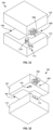
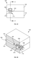
- a parting line 132 ( Figure 18 ) is formed at the perimeter of the mold cavity 130 where the fixed die 112 and the moveable die 122 meet. Clamping pressure from the main actuator and the die locking system 200 prohibits leakage of casting media from the mold cavity 130 at the parting line 132 when the moveable die 122 is closed against the fixed die 112.
- the moveable platen 120 is moved by the main actuator toward and away from the fixed or stationary platen 110 along a plurality of tie bars 140.
- the main actuator applies a force between a portion of the tie bars 140 and the moveable platen 120 to cause the moveable platen 120 to move along the tie bars 140 until the moveable die 122 closes against the fixed die 112.
- the fixed die 112 and the moveable die 122 are supported by a bottom frame (not shown) that supports and aligns the fixed die 112 and the moveable die 122.
- Guide pins in the fixed die 112 and the moveable die 122 maintain alignment between the fixed die 112 and the moveable die 122 when the die press 100 is closed.
- the main actuator closes the moveable die 122 against the fixed die 112 and applies pressure to the moveable die 122 to ensure that the moveable die 122 and fixed die 112 do not separate when the mold cavity 130 is filled with pressurized molten casting media.
- An exemplary die locking system 200 can be included in the fixed die 112 and the moveable die 122 to provide a supplemental locking force that helps the main actuator hold the moveable die 122 against the fixed die 112 during casting. In this way, the die locking system 200 can increase the maximum closing force or capacity of the die press 100.
- the die locking system 200 includes a locking pin 210 attached to the fixed die 112 and a locking cam 220 attached to the moveable die 122. T-shaped slots 114 in the fixed die 112 receive and retain the locking pins 210. When the moveable die 122 is closed against the fixed die 112, the locking pins 210 extend through holes 124 of the moveable die 122 where the locking pins 210 are engaged by the locking cams 220.
- the locking pins 210 can be removably attached to the fixed die 112 via the slots 114 or can be attached permanently to the fixed die 112 via welding or by being integrally formed with the fixed die 112.
- the locking cams 220 extend through actuator openings 126 in the sides of the moveable die 122 and are moved in and out of engagement with the locking pins 210 by hydraulic actuators 230 that are attached to the sides of the moveable die 122.
- the die locking system 200 can be added to any suitable die casting system by machining the slots 114 into the fixed die 112 and the holes 124 and openings 126 in the moveable die 122. The opposite can also be done, with the slots 114 being formed in the moveable die 122 and the holes 124 and openings 126 being formed in the fixed die 112. A mixture of both arrangements is also possible, with corresponding slots 114, holes 124, and openings 126 being formed in both the fixed die 112 and the moveable die 122.
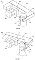
- the locking cam 220 is moved from an unlocked or open condition ( Figures 8 and 10 ) into engagement with the locking post 210 in a locked or closed condition ( Figures 7 and 9 ) by the actuator 230 that includes a shaft 232 for attaching the locking cam 220 to the actuator 230.
- FIG. 11-20 a section of the die press 100 including one die locking system 200 is shown to illustrate the steps of closing the die press 100 and locking the die locking system 200.
- the locking cam 220 is also moved into the unlocked or open condition ( Figure 14 ) to prepare for closing the moveable die 122 against the fixed die 112.
- the locking cam 220 is moved from the open or unlocked condition ( Figure 18 ) to the closed or locked condition ( Figure 20 ) by the actuator 130 extending the actuator shaft 132.
- the fixed die 312 and the moveable die 322 include corresponding ends 314, 324 that extend beyond the projected area of the fixed and moveable platens 110, 120.
- the clamping or closing force of the main actuator is applied to the fixed die 312 and the movable die 322 within the projected area of the fixed platen 110 and the moveable platen 120.
- the ends 314, 324 of the fixed and moveable dies 312, 322 extend further from the projected area of the fixed and moveable platens 110, 120 the likelihood of the parting line will separate when subjected to casting pressures increase.
- exemplary die locking systems 400, 500 are shown with different configurations for the locking cam than the die locking system 200 described above. Both of the die locking systems 400, 500 are shown separate from the die press 100 and in a locked or closed condition ( Figures 23 and 25 ) and in an unlocked or open condition ( Figures 22 and 24 ).
- the die locking system 500 operates via a pivoting movement.
- the die locking system 500 can be used with any die and die press described herein.
- the die locking system 500 includes the locking post or pin 510 that can include a flange or other feature (not shown) for engaging a corresponding slot 114 of the fixed die 112.
- Locking grooves or notches 512 in the locking post or pin 510 are shaped to engage with the locking cam 520.
- the locking cam 520 includes fingers or protrusions 522 spaced apart by a gap 524, the protrusions 522 being shaped to engage the locking grooves 512 of the locking post 510.
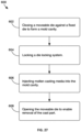
- FIG. 27 a flow chart diagramming an exemplary process 600 for high pressure and high integrity die casting with the die press and die locking systems described herein is shown.
- the moveable die is closed against the fixed die in step 602 to form a mold cavity.
- Clamping or closing force between the dies is applied by the main actuator to a desired clamping or closing force or pressure to ensure that the dies remain closed together during the casting operation. That is, the closing or clamping force is calculated to exceed the force generated by the pressure of the molten casting media applied to the surface of the mold cavity.
- the die locking system or systems attached to the dies are actuated to lock the fixed and moveable dies together.
- the actuation of the die locking system can end after a predetermined distance has been traveled by the locking cams or when a predetermined actuation pressure-an indicator of a locking force applied by the lock-has been reached.
- An optional step of monitoring the clamping or closing pressure of the main actuator or die locking systems can be performed at any time in the die casting process 600. For example, the clamping or closing force of the main actuator and die locking systems can be increased to maintain a safety margin above the force generated by the injection of pressurized molten casting media.
- the molten casting media can be injected into the mold cavity.
- the die press is then allowed to cool for a cooling time that varies depending on at least the casting alloy, size, shape, and thickness of the cast part.
- the dies are opened to allow removal of the cast part.
Landscapes
- Engineering & Computer Science (AREA)
- Mechanical Engineering (AREA)
- Moulds For Moulding Plastics Or The Like (AREA)
- Molds, Cores, And Manufacturing Methods Thereof (AREA)
Claims (15)
- Kokillenverriegelungssystem für eine Kokillengusspressvorrichtung, wobei das KokillenVerriegelungssystem aufweist:einen Verriegelungsstift (210, 410, 510),einen Verriegelungsmitnehmer (220, 420, 520), der eine schräge Eingriffsfläche zum in-Eingriff-Stehen mit einer korrespondierenden schrägen Eingriffsfläche des Verriegelungsstifts aufweist, undeinen Aktuator zum Bewegen des Verriegelungsmitnehmers (220, 420, 520) zwischen einer verriegelt-Position, in welcher der Verriegelungsmitnehmer (220, 420, 520) mit dem Verriegelungsstift (210, 410, 510) im Eingriff ist, und einer entriegelt-Position, in welcher der Verriegelungsmitnehmer (220, 420, 520) von dem Verriegelungsstift (210, 410, 510) außer Eingriff ist.
- Kokillenverriegelungssystem gemäß Anspruch 1, wobei:der Verriegelungsstift (210, 410, 510) eine Aussparung aufweist undder Verriegelungsmitnehmer (220, 420, 520) aufweist einen Vorsprung zur Einführung in die Aussparung des Verriegelungsstifts (210, 410, 510), wenn der Verriegelungsmitnehmer (220, 420, 520) in die verriegelt-Position bewegt wird.
- Kokillenverriegelungssystem gemäß Anspruch 1, wobei die Aussparung ein Loch ist, das sich durch den Verriegelungsstift (210, 410, 510) hindurcherstreckt, und
wobei, in der verriegelt-Position, ein Abschnitt des Verriegelungsmitnehmers (220, 420, 520) sich über den Verriegelungsstift (210, 410, 510) hinauserstreckt. - Kokillenverriegelungssystem gemäß Anspruch 1, wobei, in der verriegelt-Position, der Aktuator ferner betätigt werden kann, um eine zusätzliche Verriegelungskraft zwischen dem feststehenden Kokillenteil (112, 312) und dem bewegbaren Kokillenteil (122, 322) bereitzustellen.
- Kokillenverriegelungssystem gemäß Anspruch 1, wobei das Kokillenverriegelungssystem ferner aufweist eine Verbindung (534), die an dem Verriegelungsmitnehmer (220, 420, 520) angebracht ist, sodass der Verriegelungsmitnehmer (220, 420, 520) zu dem Verriegelungsstift (210, 410, 510) hin und von dem diesem weg schwenkt, wenn der Aktuator betätigt wird.
- Kokillengusspressvorrichtung (100) mit dem Kokillenverriegelungssystem gemäß Anspruch 1, wobei die Kokillengusspressvorrichtung aufweist:einen feststehenden Formenträger (110),einen bewegbaren Formenträger (120), der über eine Mehrzahl von Führungsstangen bewegbar mit dem feststehenden Formenträger (110) verbunden ist,einen Aktuator zum Bewegen des bewegbaren Formenträgers (120) zu dem feststehenden Formenträger (110) hin und von diesem weg,einen feststehenden Kokillenteil (112, 312), der an dem feststehenden Formenträger (110) angebracht ist,einen bewegbaren Kokillenteil (122, 322), der an dem bewegbaren Formenträger (120) angebracht ist,wobei das Kokillenverriegelungssystem (200, 500) an dem feststehenden Kokillenteil (112, 312) und dem bewegbaren Kokillenteil (122, 322) angebracht ist,wobei der Verriegelungsstift (210, 410, 510) an dem feststehenden Kokillenteil (112, 312) angebracht ist und sich von diesem aus erstreckt,wobei der Aktuator (230, 430, 530) an dem bewegbaren Kokillenteil (122, 322) angebracht ist, wobei der Aktuator (230, 430, 530) einen Schaft (232, 432, 532) aufweist, wobei der Verriegelungsmitnehmer (220, 420, 520) an dem Schaft (232, 432, 532) des Aktuators (230, 430, 530) angebracht ist, wobei der Aktuator (230, 430, 530) den Schaft (232, 432, 532) ausfährt, um den Verriegelungsmitnehmer (220, 420, 520) zwischen der verriegelt-Position, in welcher der Verriegelungsmitnehmer (220, 420, 520) mit dem Verriegelungsstift (210, 410, 510) im Eingriff ist, um eine zusätzliche Verriegelungskraft auf den feststehenden und den bewegbaren Kokillenteil aufzubringen, und der entriegelt-Position zu bewegen, in welcher der Verriegelungsmitnehmer (220, 420, 520) von dem Verriegelungsstift (210, 410, 510) entriegelt ist.
- Kokillengusspressvorrichtung gemäß Anspruch 6, wobei der bewegbare Kokillenteil (122, 322) aufweist:ein Loch (124) zum Aufnehmen des Verriegelungsstifts (210, 410, 510) undeine Öffnung (126), die sich von einer Seite des bewegbaren Kokillenteils (122, 322) aus erstreckt, um das Loch zum Aufnehmen des Verriegelungsstifts (210, 410, 510) zu kreuzen,wobei der Verriegelungsmitnehmer (220, 420, 520) innerhalb der Öffnung (126) angeordnet ist, undwobei der Aktuator an der Seite des bewegbaren Kokillenteils (122, 322) angebracht ist, um den Verriegelungsmitnehmer (220, 420, 520) innerhalb der Öffnung (126) zwischen der verriegelt-Position und der entriegelt-Position zu bewegen.
- Kokillengusspressvorrichtung gemäß Anspruch 6, wobei der feststehende Kokillenteil (112) und der bewegbare Kokillenteil (122, 322) jeweils eine Trennfläche haben, die breiter als eine Trennfläche des feststehenden Formenträgers (110) und des bewegbaren Formenträgers (120) ist.
- Kokillengusspressvorrichtung gemäß Anspruch 6, wobeider Verriegelungsstift (210, 410, 510) einen Flansch (212) aufweist,der feststehende Kokillenteil (112) einen Schlitz (114) zum Aufnehmen des Verriegelungsstifts (210, 410, 510) und des Flanschs (212) aufweist,das Kokillenverriegelungssystem (200) abnehmbar an dem feststehenden Kokillenteil (112) und dem bewegbaren Kokillenteil (122) angebracht ist,der Verriegelungsstift (210) ferner eine Aussparung aufweist undder Verriegelungsmitnehmer (220, 420, 520) aufweist einen Vorsprung zur Einführung in die Aussparung des Verriegelungsstifts, wenn der Verriegelungsmitnehmer (220, 420, 520) in die verriegelt-Position bewegt wird.
- Kokillengusspressvorrichtung gemäß Anspruch 9, wobei die Aussparung ein Loch ist, das sich durch den Verriegelungsstift (210, 410, 510) hindurcherstreckt, und
wobei, in der verriegelt-Position, ein Abschnitt des Verriegelungsmitnehmers (220, 420, 520) sich über den Verriegelungsstift (210, 410, 510) hinauserstreckt. - Kokillengusspressvorrichtung gemäß Anspruch 6, wobei, in der verriegelt-Position, der Aktuator ferner betätigt werden kann, um den Schaft (232, 432, 532) auszufahren, um die schräge Eingriffsfläche des Verriegelungsmitnehmers (220, 420, 520) gegen die korrespondierende schräge Eingriffsfläche des Verriegelungsstifts zu zwingen, um eine zusätzliche Verriegelungskraft zwischen dem feststehenden Kokillenteil und dem bewegbaren Kokillenteil (122, 322) bereitzustellen.
- Kokillengusspressvorrichtung gemäß irgendeinem der vorigen Ansprüche, wobei das Kokillenverriegelungssystem ferner eine Verbindung (534) aufweist, die an dem Verriegelungsmitnehmer (220, 420, 520) angebracht ist, sodass der Verriegelungsmitnehmer (220, 420, 520) zu dem Verriegelungsstift (210, 410, 510) hin und von dem diesem weg schwenkt, wenn der Aktuator betätigt wird.
- Verfahren zum Spritzgießen unter Verwenden des Kokillenverriegelungssystems gemäß Anspruch 1, wobei das Verfahren aufweist:Schließen des bewegbaren Kokillenteils gegen den feststehenden Kokillenteil, um einen Formhohlraum zu bilden,Betätigen des Aktuators des Kokillenverriegelungssystems, um einen Schaft auszufahren, um den Verriegelungsmitnehmer zu bewegen, um mit dem Verriegelungsstift in Eingriff zu kommen, wobei der Aktuator an dem bewegbaren Kokillenteil angebracht ist und sich der Verriegelungsstift von dem feststehenden Kokillenteil aus erstreckt und an diesem angebracht ist,Betätigen des Kokillenverriegelungssystems, um eine zusätzliche Verriegelungskraft zwischen dem feststehenden Kokillenteil und dem bewegbaren Kokillenteil bereitzustellen, undEinspritzen von geschmolzenem Gießmedium in den Formhohlraum.
- Verfahren zum Spritzgießen gemäß Anspruch 13, wobei:das geschmolzene Gießmedium in den Formhohlraum eingespritzt wird mit einem Druck, der eine Einspritzkraft auf den bewegbaren Kokillenteil generiert, unddie Einspritzkraft größer ist als eine maximale Klemmkraft eines Hauptaktuators, der verwendet wird, um den bewegbaren Kokillenteil gegen den feststehenden Kokillenteil zu schließen,wobei eine Gesamtklemmkraft gleich der Summe einer Klemmkraft, die von einem Hauptaktuator generiert wird, der verwendet wird, um den bewegbaren Kokillenteil gegen den feststehenden Kokillenteil zu schließen, und der zusätzlichen Kraft ist, die von dem Kokillenverriegelungssystem generiert wird,wobei das geschmolzene Gießmedium in den Formhohlraum eingespritzt wird mit einem Einspritzdruck, der eine Einspritzkraft auf den bewegbaren Kokillenteil generiert, undwobei die Gesamtklemmkraft größer als die Einspritzkraft ist.
- Verfahren zum Spritzgießen gemäß Anspruch 13, aufweisend:Überwachen einer Einspritzkraft, die auf den bewegbaren Kokillenteil ausgeübt wird durch die Einspritzung des geschmolzenen Gießmediums in den Formhohlraum mit einem Einspritzdruck, undEinstellen wenigstens eines von einer Klemmkraft, die von einem Hauptaktuator generiert wird, der verwendet wird, um den bewegbaren Kokillenteil gegen den feststehenden Kokillenteil zu schließen, und der zusätzlichen Verriegelungskraft, die von dem Kokillenverriegelungssystem generiert wird, sodass eine Gesamtklemmkraft um einen vorbestimmten Sicherheitszuschlag größer ist als die Einspritzkraft, wobei die Gesamtklemmkraft gleich der Summe der Klemmkraft, die von dem Hauptaktuator generiert wird, und der Kokillenverriegelungskraft ist, die von dem Kokillenverriegelungssystem generiert wird.
Priority Applications (1)
| Application Number | Priority Date | Filing Date | Title |
|---|---|---|---|
| EP25160096.1A EP4596141A1 (de) | 2021-06-21 | 2022-06-21 | Matrizenverriegelungssystem und verfahren zur verwendung davon |
Applications Claiming Priority (3)
| Application Number | Priority Date | Filing Date | Title |
|---|---|---|---|
| US202163259079P | 2021-06-21 | 2021-06-21 | |
| US202163244958P | 2021-09-16 | 2021-09-16 | |
| US17/506,282 US12090548B2 (en) | 2021-06-21 | 2021-10-20 | Die locking system and methods of using the same |
Related Child Applications (1)
| Application Number | Title | Priority Date | Filing Date |
|---|---|---|---|
| EP25160096.1A Division EP4596141A1 (de) | 2021-06-21 | 2022-06-21 | Matrizenverriegelungssystem und verfahren zur verwendung davon |
Publications (3)
| Publication Number | Publication Date |
|---|---|
| EP4108359A1 EP4108359A1 (de) | 2022-12-28 |
| EP4108359B1 true EP4108359B1 (de) | 2025-02-26 |
| EP4108359C0 EP4108359C0 (de) | 2025-02-26 |
Family
ID=82163524
Family Applications (2)
| Application Number | Title | Priority Date | Filing Date |
|---|---|---|---|
| EP25160096.1A Pending EP4596141A1 (de) | 2021-06-21 | 2022-06-21 | Matrizenverriegelungssystem und verfahren zur verwendung davon |
| EP22180152.5A Active EP4108359B1 (de) | 2021-06-21 | 2022-06-21 | Blaskopfarretierungsystem und verwendungsverfahren dafür |
Family Applications Before (1)
| Application Number | Title | Priority Date | Filing Date |
|---|---|---|---|
| EP25160096.1A Pending EP4596141A1 (de) | 2021-06-21 | 2022-06-21 | Matrizenverriegelungssystem und verfahren zur verwendung davon |
Country Status (5)
| Country | Link |
|---|---|
| US (2) | US12090548B2 (de) |
| EP (2) | EP4596141A1 (de) |
| CN (1) | CN115570113A (de) |
| CA (1) | CA3164541A1 (de) |
| MX (1) | MX2022007821A (de) |
Families Citing this family (2)
| Publication number | Priority date | Publication date | Assignee | Title |
|---|---|---|---|---|
| ES2955741B2 (es) * | 2022-04-29 | 2024-05-17 | Comercial De Utiles Y Moldes Sa | Dispositivo de seguridad para moldes de inyección |
| CN116461042B (zh) * | 2023-04-23 | 2023-11-07 | 广东荣旭智能技术有限公司 | 一种高精度注塑设备及其控制使用方法 |
Family Cites Families (14)
| Publication number | Priority date | Publication date | Assignee | Title |
|---|---|---|---|---|
| US2319479A (en) | 1939-10-18 | 1943-05-18 | Grotelite Company | Self-locking plastic injection mold |
| US2848771A (en) | 1955-03-03 | 1958-08-26 | Buehler Ag Geb | Apparatus for closing and locking of die casting machines and the like |
| US2869190A (en) * | 1956-04-18 | 1959-01-20 | Schofield H Bruce | Two-stage power apparatus |
| US3195186A (en) | 1962-06-13 | 1965-07-20 | Inv S Finance Corp | Apparatus for clamping mold parts |
| US3353221A (en) * | 1963-11-13 | 1967-11-21 | Loma Ind Inc | Locking device for injection molding apparatus |
| US4184835A (en) | 1978-09-28 | 1980-01-22 | General Electric Company | Mold apparatus |
| US4372738A (en) * | 1981-10-27 | 1983-02-08 | Pemco-Kalamazoo, Inc. | Collet lock for a mold assembly |
| JPH0763998B2 (ja) * | 1986-08-11 | 1995-07-12 | 松下電器産業株式会社 | 金型パ−ト面締結装置 |
| DE3722340A1 (de) * | 1987-07-07 | 1989-01-19 | Battenfeld Fischer Blasform | Schliessvorrichtung fuer formen zum herstellen von gegenstaenden aus thermoplastischem kunststoff |
| JP3193401B2 (ja) * | 1991-07-10 | 2001-07-30 | オリンパス光学工業株式会社 | 射出成形用金型および射出成形方法 |
| US5542465A (en) * | 1994-11-10 | 1996-08-06 | Wolniak; Robert T. | Die space access system for tie-bar style die-casting machines |
| CA2422638A1 (en) | 2002-04-25 | 2003-10-25 | Conix Corporation | Secondary mold clamping lock apparatus and method |
| HUE051405T2 (hu) * | 2017-11-17 | 2021-03-01 | Nemak Sab De Cv | Öntõberendezés öntvények fémolvadékból történõ elõállítására |
| JP7651281B2 (ja) * | 2020-09-16 | 2025-03-26 | キヤノン株式会社 | 金型、射出成形システム、および成形品の製造方法 |
-
2021
- 2021-10-20 US US17/506,282 patent/US12090548B2/en active Active
-
2022
- 2022-06-21 CA CA3164541A patent/CA3164541A1/en active Pending
- 2022-06-21 EP EP25160096.1A patent/EP4596141A1/de active Pending
- 2022-06-21 MX MX2022007821A patent/MX2022007821A/es unknown
- 2022-06-21 EP EP22180152.5A patent/EP4108359B1/de active Active
- 2022-06-21 CN CN202210705994.1A patent/CN115570113A/zh active Pending
-
2024
- 2024-09-16 US US18/886,449 patent/US20250001490A1/en active Pending
Also Published As
| Publication number | Publication date |
|---|---|
| EP4596141A1 (de) | 2025-08-06 |
| US20250001490A1 (en) | 2025-01-02 |
| MX2022007821A (es) | 2022-12-22 |
| CA3164541A1 (en) | 2022-12-21 |
| US12090548B2 (en) | 2024-09-17 |
| EP4108359A1 (de) | 2022-12-28 |
| CN115570113A (zh) | 2023-01-06 |
| US20220402020A1 (en) | 2022-12-22 |
| EP4108359C0 (de) | 2025-02-26 |
Similar Documents
| Publication | Publication Date | Title |
|---|---|---|
| US20250001490A1 (en) | Die locking system and methods of using the same | |
| JP3544539B2 (ja) | 内部空隙が無く外側のヒケが存在しない均質な射出成形品を製造する方法 | |
| HK48489A (en) | Hot sprue valve assembly for an injection molding machine | |
| US6042363A (en) | Die for injection molding | |
| CN112247104A (zh) | 一种铝合金压铸模具 | |
| US5964274A (en) | Die assembly for a die casting machine | |
| JP7651281B2 (ja) | 金型、射出成形システム、および成形品の製造方法 | |
| JP2857841B2 (ja) | カセット式射出成形金型装置 | |
| EP2011622A1 (de) | Plattenformgesenk, spiegelplatte und verfahren zur herstellung einer spiegelplatte | |
| WO1994021440A1 (en) | Method of molding plastic structural parts | |
| JP2004276447A (ja) | 成形用金型およびその段替え方法 | |
| EP3797966B1 (de) | Vorrichtung zum automatischen beschneiden von anspritzanschnitten und verfahren | |
| JPH0530608B2 (de) | ||
| JPH09141714A (ja) | 射出成形用金型 | |
| JP4637609B2 (ja) | チルベント入れ子 | |
| JP3842608B2 (ja) | 射出成形用金型 | |
| JP2009078279A (ja) | 真空ダイカスト用金型および真空ダイカスト法 | |
| JPH09141699A (ja) | 射出成形用金型 | |
| JP3114161B2 (ja) | 金型装置 | |
| JP6134776B1 (ja) | ダイカスト用金型 | |
| JPH11333849A (ja) | 多材料成形用金型装置およびこの金型装置を用いた多材料成形方法 | |
| JPH0222018A (ja) | 射出成形機 | |
| JPH0716778B2 (ja) | 無孔質ダイキャスト装置 | |
| JP2009248449A (ja) | 射出成形装置及び射出成形方法 | |
| JPH09131766A (ja) | 射出成形用金型 |
Legal Events
| Date | Code | Title | Description |
|---|---|---|---|
| PUAI | Public reference made under article 153(3) epc to a published international application that has entered the european phase |
Free format text: ORIGINAL CODE: 0009012 |
|
| STAA | Information on the status of an ep patent application or granted ep patent |
Free format text: STATUS: THE APPLICATION HAS BEEN PUBLISHED |
|
| AK | Designated contracting states |
Kind code of ref document: A1 Designated state(s): AL AT BE BG CH CY CZ DE DK EE ES FI FR GB GR HR HU IE IS IT LI LT LU LV MC MK MT NL NO PL PT RO RS SE SI SK SM TR |
|
| STAA | Information on the status of an ep patent application or granted ep patent |
Free format text: STATUS: REQUEST FOR EXAMINATION WAS MADE |
|
| 17P | Request for examination filed |
Effective date: 20230628 |
|
| RBV | Designated contracting states (corrected) |
Designated state(s): AL AT BE BG CH CY CZ DE DK EE ES FI FR GB GR HR HU IE IS IT LI LT LU LV MC MK MT NL NO PL PT RO RS SE SI SK SM TR |
|
| STAA | Information on the status of an ep patent application or granted ep patent |
Free format text: STATUS: EXAMINATION IS IN PROGRESS |
|
| 17Q | First examination report despatched |
Effective date: 20231006 |
|
| GRAP | Despatch of communication of intention to grant a patent |
Free format text: ORIGINAL CODE: EPIDOSNIGR1 |
|
| STAA | Information on the status of an ep patent application or granted ep patent |
Free format text: STATUS: GRANT OF PATENT IS INTENDED |
|
| INTG | Intention to grant announced |
Effective date: 20240926 |
|
| GRAS | Grant fee paid |
Free format text: ORIGINAL CODE: EPIDOSNIGR3 |
|
| GRAA | (expected) grant |
Free format text: ORIGINAL CODE: 0009210 |
|
| STAA | Information on the status of an ep patent application or granted ep patent |
Free format text: STATUS: THE PATENT HAS BEEN GRANTED |
|
| AK | Designated contracting states |
Kind code of ref document: B1 Designated state(s): AL AT BE BG CH CY CZ DE DK EE ES FI FR GB GR HR HU IE IS IT LI LT LU LV MC MK MT NL NO PL PT RO RS SE SI SK SM TR |
|
| REG | Reference to a national code |
Ref country code: GB Ref legal event code: FG4D |
|
| REG | Reference to a national code |
Ref country code: CH Ref legal event code: EP |
|
| REG | Reference to a national code |
Ref country code: DE Ref legal event code: R096 Ref document number: 602022011011 Country of ref document: DE |
|
| REG | Reference to a national code |
Ref country code: IE Ref legal event code: FG4D |
|
| U01 | Request for unitary effect filed |
Effective date: 20250325 |
|
| U07 | Unitary effect registered |
Designated state(s): AT BE BG DE DK EE FI FR IT LT LU LV MT NL PT RO SE SI Effective date: 20250331 |
|
| PG25 | Lapsed in a contracting state [announced via postgrant information from national office to epo] |
Ref country code: RS Free format text: LAPSE BECAUSE OF FAILURE TO SUBMIT A TRANSLATION OF THE DESCRIPTION OR TO PAY THE FEE WITHIN THE PRESCRIBED TIME-LIMIT Effective date: 20250526 |
|
| PG25 | Lapsed in a contracting state [announced via postgrant information from national office to epo] |
Ref country code: PL Free format text: LAPSE BECAUSE OF FAILURE TO SUBMIT A TRANSLATION OF THE DESCRIPTION OR TO PAY THE FEE WITHIN THE PRESCRIBED TIME-LIMIT Effective date: 20250226 |
|
| PG25 | Lapsed in a contracting state [announced via postgrant information from national office to epo] |
Ref country code: ES Free format text: LAPSE BECAUSE OF FAILURE TO SUBMIT A TRANSLATION OF THE DESCRIPTION OR TO PAY THE FEE WITHIN THE PRESCRIBED TIME-LIMIT Effective date: 20250226 |
|
| PG25 | Lapsed in a contracting state [announced via postgrant information from national office to epo] |
Ref country code: NO Free format text: LAPSE BECAUSE OF FAILURE TO SUBMIT A TRANSLATION OF THE DESCRIPTION OR TO PAY THE FEE WITHIN THE PRESCRIBED TIME-LIMIT Effective date: 20250526 Ref country code: IS Free format text: LAPSE BECAUSE OF FAILURE TO SUBMIT A TRANSLATION OF THE DESCRIPTION OR TO PAY THE FEE WITHIN THE PRESCRIBED TIME-LIMIT Effective date: 20250626 |
|
| PG25 | Lapsed in a contracting state [announced via postgrant information from national office to epo] |
Ref country code: HR Free format text: LAPSE BECAUSE OF FAILURE TO SUBMIT A TRANSLATION OF THE DESCRIPTION OR TO PAY THE FEE WITHIN THE PRESCRIBED TIME-LIMIT Effective date: 20250226 |
|
| PG25 | Lapsed in a contracting state [announced via postgrant information from national office to epo] |
Ref country code: GR Free format text: LAPSE BECAUSE OF FAILURE TO SUBMIT A TRANSLATION OF THE DESCRIPTION OR TO PAY THE FEE WITHIN THE PRESCRIBED TIME-LIMIT Effective date: 20250527 |
|
| U20 | Renewal fee for the european patent with unitary effect paid |
Year of fee payment: 4 Effective date: 20250628 |
|
| PG25 | Lapsed in a contracting state [announced via postgrant information from national office to epo] |
Ref country code: SM Free format text: LAPSE BECAUSE OF FAILURE TO SUBMIT A TRANSLATION OF THE DESCRIPTION OR TO PAY THE FEE WITHIN THE PRESCRIBED TIME-LIMIT Effective date: 20250226 |
|
| PG25 | Lapsed in a contracting state [announced via postgrant information from national office to epo] |
Ref country code: CZ Free format text: LAPSE BECAUSE OF FAILURE TO SUBMIT A TRANSLATION OF THE DESCRIPTION OR TO PAY THE FEE WITHIN THE PRESCRIBED TIME-LIMIT Effective date: 20250226 |
|
| PG25 | Lapsed in a contracting state [announced via postgrant information from national office to epo] |
Ref country code: SK Free format text: LAPSE BECAUSE OF FAILURE TO SUBMIT A TRANSLATION OF THE DESCRIPTION OR TO PAY THE FEE WITHIN THE PRESCRIBED TIME-LIMIT Effective date: 20250226 |
|
| PLBE | No opposition filed within time limit |
Free format text: ORIGINAL CODE: 0009261 |
|
| STAA | Information on the status of an ep patent application or granted ep patent |
Free format text: STATUS: NO OPPOSITION FILED WITHIN TIME LIMIT |
|
| REG | Reference to a national code |
Ref country code: CH Ref legal event code: L10 Free format text: ST27 STATUS EVENT CODE: U-0-0-L10-L00 (AS PROVIDED BY THE NATIONAL OFFICE) Effective date: 20260107 |
|
| REG | Reference to a national code |
Ref country code: CH Ref legal event code: H13 Free format text: ST27 STATUS EVENT CODE: U-0-0-H10-H13 (AS PROVIDED BY THE NATIONAL OFFICE) Effective date: 20260127 |
|
| PG25 | Lapsed in a contracting state [announced via postgrant information from national office to epo] |
Ref country code: MC Free format text: LAPSE BECAUSE OF FAILURE TO SUBMIT A TRANSLATION OF THE DESCRIPTION OR TO PAY THE FEE WITHIN THE PRESCRIBED TIME-LIMIT Effective date: 20250226 |
|
| 26N | No opposition filed |
Effective date: 20251127 |
|
| PG25 | Lapsed in a contracting state [announced via postgrant information from national office to epo] |
Ref country code: IE Free format text: LAPSE BECAUSE OF NON-PAYMENT OF DUE FEES Effective date: 20250621 |
|
| PG25 | Lapsed in a contracting state [announced via postgrant information from national office to epo] |
Ref country code: CH Free format text: LAPSE BECAUSE OF NON-PAYMENT OF DUE FEES Effective date: 20250630 |