EP4103442B1 - System zum befestigen einer seitenverglasung eines transportmittels mit einem schloss - Google Patents
System zum befestigen einer seitenverglasung eines transportmittels mit einem schloss Download PDFInfo
- Publication number
- EP4103442B1 EP4103442B1 EP21709070.3A EP21709070A EP4103442B1 EP 4103442 B1 EP4103442 B1 EP 4103442B1 EP 21709070 A EP21709070 A EP 21709070A EP 4103442 B1 EP4103442 B1 EP 4103442B1
- Authority
- EP
- European Patent Office
- Prior art keywords
- edge
- pane
- external
- internal
- glazing
- Prior art date
- Legal status (The legal status is an assumption and is not a legal conclusion. Google has not performed a legal analysis and makes no representation as to the accuracy of the status listed.)
- Active
Links
Images

Classifications
-
- B—PERFORMING OPERATIONS; TRANSPORTING
- B61—RAILWAYS
- B61D—BODY DETAILS OR KINDS OF RAILWAY VEHICLES
- B61D25/00—Window arrangements peculiar to rail vehicles
-
- B—PERFORMING OPERATIONS; TRANSPORTING
- B60—VEHICLES IN GENERAL
- B60J—WINDOWS, WINDSCREENS, NON-FIXED ROOFS, DOORS, OR SIMILAR DEVICES FOR VEHICLES; REMOVABLE EXTERNAL PROTECTIVE COVERINGS SPECIALLY ADAPTED FOR VEHICLES
- B60J1/00—Windows; Windscreens; Accessories therefor
- B60J1/004—Mounting of windows
- B60J1/007—Mounting of windows received in frames to be attached to vehicle
-
- B—PERFORMING OPERATIONS; TRANSPORTING
- B60—VEHICLES IN GENERAL
- B60J—WINDOWS, WINDSCREENS, NON-FIXED ROOFS, DOORS, OR SIMILAR DEVICES FOR VEHICLES; REMOVABLE EXTERNAL PROTECTIVE COVERINGS SPECIALLY ADAPTED FOR VEHICLES
- B60J1/00—Windows; Windscreens; Accessories therefor
- B60J1/08—Windows; Windscreens; Accessories therefor arranged at vehicle sides
- B60J1/085—Windows; Windscreens; Accessories therefor arranged at vehicle sides removably mounted
-
- B—PERFORMING OPERATIONS; TRANSPORTING
- B60—VEHICLES IN GENERAL
- B60J—WINDOWS, WINDSCREENS, NON-FIXED ROOFS, DOORS, OR SIMILAR DEVICES FOR VEHICLES; REMOVABLE EXTERNAL PROTECTIVE COVERINGS SPECIALLY ADAPTED FOR VEHICLES
- B60J1/00—Windows; Windscreens; Accessories therefor
- B60J1/08—Windows; Windscreens; Accessories therefor arranged at vehicle sides
- B60J1/10—Windows; Windscreens; Accessories therefor arranged at vehicle sides fixedly mounted
-
- B—PERFORMING OPERATIONS; TRANSPORTING
- B60—VEHICLES IN GENERAL
- B60Y—INDEXING SCHEME RELATING TO ASPECTS CROSS-CUTTING VEHICLE TECHNOLOGY
- B60Y2200/00—Type of vehicle
- B60Y2200/30—Railway vehicles
Definitions
- the invention relates to the fixing of a side glazing of a means of transport, and in particular of a train glazing, to a peripheral bay, generally metallic, said glazing being a multiple, fixed glazing.
- This type of glazing is usually fixed to the bay of the train in a vertical position.
- the invention relates more particularly to the fixing of a side glazing having an outer face which faces an outer space and an inner face which faces an inner space, said outer face of the glazing being in continuity of appearance with an outer face or an outer flank of said opening over its entire periphery.
- Continuity of appearance does not mean that there is contact between the outer face of the glazing and the outer face of the opening because it is known that such contact must be avoided, especially when the opening is metallic; continuity of appearance implies that, seen in vertical cross-section, the outer face of the opening is in continuity with the outer face of the glazing with a non-zero distance between them.
- Such an external glazing structure is then mechanically and/or chemically fixed to the bay that the glazing is to close.
- the internal structure integrates the spacer 71 and the bead of mastic 76 which are both located on the internal periphery of the glazing cavity 8 and the external structure integrates the bead of glue 70 and the frame 72.
- the aim of the invention is to make it possible to produce multiple, fixed glazing, fixed to a bay of a means of transport body from the outside, without needing to access the interior for replacement.
- Another aim is to make it possible to produce such glazing without providing an external rigid frame and in particular without a metal or metal alloy frame external to the glazing itself. Indeed, it can be difficult to manage the resistance over time, in particular the resistance to corrosion, of a metal or metal alloy frame.
- the glazing is then less expensive and lighter.
- this frame generally reduces the clear glazing, so removing it can increase this clear glazing, for an identical bay size.
- the glazing according to the invention is remarkable in that said internal structure comprises a hanging cavity having a centripetal bottom and a centrifugal opening, in that said bay comprises an internal flank having a fixing hole which is located more centrifugal than said edge of said internal pane and having an axis parallel to said edge of said internal pane and in that a lock is fixed to said internal flank by a fixing means passing through said fixing hole, said lock having a lateral wing extending inside said hanging cavity and opposite an edge of said intermediate face of the internal pane by 90° rotation of said lateral wing.
- Said 90° rotation can be the rotation of said side wing alone on itself or the rotation of the complete lock on itself.
- each lock preferably has a single side wing.
- the 90° rotation of the lock on itself is preferably achieved by rotation around the axis of the fixing hole.
- the lock is thus introduced into an applique space, which is located between the glazing and a bay crosspiece adjacent, with the side wing oriented along this space, then the lock is rotated on itself to make the side wing enter said attachment cavity.
- the lock thus works like a latch. It is this rotation which allows in one direction to fix or attach the glazing to the bay and in the opposite direction to detach the glazing from the bay.
- Said hanging cavity is preferably formed by a groove located at the location of the lock or by an elongated rail; each horizontal or vertical edge of the glazing then preferably comprises a single rail; preferably, there is then no rail in the corners of the glazing.
- Said attachment cavity preferably has a depth, i.e. a distance between its centripetal bottom and its centrifugal opening, of between 2.0 and 15.0 mm, preferably between 3.0 and 10.0 mm. This distance is both large for good fixing of the glazing, i.e. good maintenance of the side wing in the attachment cavity, and small so as not to restrict the clear glazing too much.
- said rotation of the lock on itself is eccentric so that said lateral wing moves away from said axis of the fixing hole during the movement of the penetration of said lateral wing into said attachment cavity.
- said internal structure does not protrude in the centrifugal direction further than the edge of said outer pane or the edge of said inner pane and more preferably said internal structure does not protrude in the centrifugal direction further than the edge of said outer pane or the edge of said inner pane.
- said inner glass sheet may have dimensions identical (length, height) to the dimensions of the inner pane.
- the said inner pane can itself be laminated but then, to facilitate manufacturing, the constituent sheets of the pane preferably have identical dimensions (length, height).
- the edge of said outer pane or the edge of said outer glass sheet is located in centrifugal overhang of the edge of said inner pane along at least part of the length of the edge of said outer pane or said outer glass sheet and preferably along the entire length of the edge (i.e. along the entire periphery of the edge) of said outer pane or said outer glass sheet.
- the said overhang is between 5.0 and 30.0 mm, and preferably between 8.0 and 20.0 mm. This contributes to the compactness of the fixing.
- overhang is used in reference to the center of the sheet of glass, the window, or the glazing; it designates a centrifugal positioning, further from this center than what is used for reference.
- said edge of said plastic sheet and/or said edge of said inner glass sheet is (or are) located centripetally set back from the edge of said inner pane along at least part of the length of the edge of said plastic sheet and/or said inner glass sheet and preferably along the entire length of the edge (i.e. along the entire periphery of the edge) of said plastic sheet and/or said inner glass sheet.
- Said withdrawal is preferably between 1.0 and 10.0 mm, and more preferably between 2.0 and 8.0 mm. This contributes to the compactness of the fixing.
- the concept of withdrawal is used in reference to the center of the glass sheet, the window, or the glazing; it designates a centripetal positioning, closer to this center, than what is used for reference.
- Said glazing preferably comprises a spacer which is located between said inner glass sheet and said inner pane, set back from the edges of said inner glass sheet and said inner pane while being spaced apart, seen in cross-section, by a distance further at the periphery than the transverse continuity of the edge of said outer glass sheet, said the gap being between 2.0 and 30.0 mm, and preferably between 5.0 and 20.0 mm, or even between 6.0 and 15.0 mm.
- At least one sheet of plastic material in the glazing may also have a sound insulation capacity.
- the edge of said outer pane or the edge of said inner glass sheet comprises a centrifugal lip made of plastic material. This lip contributes to the protection of the lock located further inside.
- This distance between said outer face of the glazing and said outer face of said bay is preferably between 5.0 and 25.0 mm and more preferably between 8.0 and 15.0 mm, which is very small.
- the body of the lock preferably has a diameter or height identical to this distance, in order to be able to be introduced into the application space.
- the side wing of the lock preferably has a width identical to this distance in order to be able to be introduced into the application space.
- an external seal is present in contact between on the one hand an edge of said external face of the bay and on the other hand the edge of said external pane or the edge of said external glass sheet when the external pane is laminated, said external seal preferably having a height of between 5.0 and 30.0 mm, and preferably between 8.0 and 20.0 mm.
- centrifugal lip When a centrifugal lip is present, it can provide a bottom for the outer seal to prevent it from reaching the latch.
- the glazing according to the invention preferably does not include any element projecting outwards, beyond the outer face of said glazing, which is also the outer face of said outer window, in order to reduce friction in the air for the means of transport.
- the glazing can then be positioned in continuity of external appearance with the bodywork bay, the outer face of the glazing being at a distance from the outer face of the bay.
- An internal seal is furthermore preferably present at the contact between on the one hand said internal side of the bay and on the other hand said internal face of the internal window.
- the glazing clearance is relatively large; it is, for the most part, defined by the position of the spacer.
- the glazing fixing system according to the invention is a system for fixing a side glazing of a means of transport. It is a reliable system, although the glazing is intended to undergo numerous vibrations due to its use as side glazing of a means of transport.
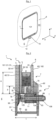
- FIG. 1 illustrates a left side glazing 1 according to the invention of a means of transport, this glazing being positioned vertically and fixed to a bay 9 of the bodywork of this means of transport.
- FIG. 1 is a schematic view of the exterior.
- side glazing As this is side glazing, it extends essentially along the axis generally called the "X axis" of the means of transport, which is the central longitudinal axis of advance of the means of transport equipped with the glazing according to the invention as side glazing (here on the left side) and which corresponds to the Xen axis figure 1 .
- the Y axis is the vertical axis and the Z axis is the transverse axis.
- centripetal and that of "centrifugal” is to be considered in the plane of the sheet in figure 1 , or in a general plane of the glazing when it is considered flat, expressed in relation to the center of the glazing, according to the X and Y axes; the centripetal direction is towards this center while the centrifugal direction moves away from this center.
- This glazing 1 is fixed. It is in one piece, without an opening window on the inside as is known for example from international patent application No. WO 2016/042270 ; however, although not described in detail here, the invention could be applied to such glazing with an openable window.
- This glazing 1 has an exterior face 101 which faces the exterior space E and an interior face 102 which faces the interior space I.
- the internal structure 7 is called “internal” because it is located on the internal periphery of the outer pane 2 and on the internal periphery of the inner pane 6, being more towards the center (more centripetal) than the peripheral edge 20, 60 respectively of the outer pane 2 and of the inner pane 6; that is to say that the internal structure 7 does not protrude in a centrifugal direction beyond the peripheral edges 20, 60.
- Sheets 3, 4, 5 and panes 2, 6 of glazing 1 are each in one piece.
- the inner pane 6 is a monolithic glass sheet having a thickness of between 3.0 and 8.0 mm, for example 5.0 mm.
- the outer pane 2 is laminated and comprises, starting from the outer space E: at least one outer glass sheet 3, one inner glass sheet 5, and one sheet of plastic material 4 located between the outer glass sheet 3 and the inner glass sheet 5, each sheet 3, 4, 5 of the outer pane 2 having a peripheral edge 30, 40, 50.
- the outer glass sheet 3 has an outer face 31 which is oriented towards the exterior E, an intermediate face 32 which is oriented towards the plastic sheet 4, intermediate, with the peripheral edge 30 located between these two faces.
- the inner glass sheet 5 has an intermediate face 51 which is oriented towards the plastic sheet 4, an inner face 52 which is oriented towards the glazing cavity 8, with the peripheral edge 50 located between these two faces.
- the plastic sheet 4 has an outer intermediate face 41 which is oriented towards the intermediate face 32 and which is here in contact with this intermediate face 32, an inner intermediate face 42 which is oriented towards the intermediate face 51 and which is here in contact with this intermediate face 51, with the peripheral edge 40 which is located between these two intermediate faces 41, 42.
- the outer glass sheet 3 is for example a glass sheet having a thickness of between 0.5 and 8.0 mm, for example 6.0 mm.
- the interlayer plastic sheet 4 is for example a polyvinyl butyral (PVB) sheet having a thickness of between 0.50 and 1.50 mm, for example 0.76 mm.
- This plastic sheet 4 preferably has the same length and height dimensions as the outer glass sheet 3.
- the inner glass sheet 5 is a glass sheet having a thickness of between 0.5 and 8.0 mm, for example 5.0 mm.
- glazing 1 thus has a total thickness t' of 26.76 mm.
- the glazing 1 is a fixed glazing in the sense that the internal structure 7 is also intended to allow the glazing 1 to be fixed to a structure 9 of the means transport (here the train), without the possibility of moving relative to this structure 9.
- the glazing 1 is a multiple glazing in the sense that it comprises several panes 20, 60 as well as the glazing cavity 8 which is located between the two panes 20, 60, this cavity being filled with air or gas, preferably neutral such as argon or krypton; this cavity contributes to the thermal insulation provided by the glazing 1.
- the internal structure 7 thus makes it possible to keep the two panes 20, 60 at a distance from each other, with a constant distance between the two panes 20, 60, here 10.0 mm.
- the internal structure 7 comprises a hooking cavity 77 having a centripetal bottom 78 and a centrifugal opening 79.
- This attachment cavity 77 preferably has a depth p, that is to say a distance between its centripetal bottom 78 and its centrifugal opening 79, of between 2.0 and 15.0 mm, preferably between 3.0 and 10.0 mm and here 7.0 mm.
- the bay 9 comprises an external flank 91, oriented vertically and facing the exterior space, an internal flank 92, oriented vertically and facing the exterior space, these two flanks being connected by a crosspiece 90, horizontal along the horizontal edges and vertical along the vertical edges.
- this crosspiece can also be oblique or cross-shaped. This connection forms an application space 95, in which the glazing is positioned and then fixed during its installation in the bay that it must close.
- Bay 9 is thus peripheral: it goes all the way around glazing 1.
- the inner flank 92 extends in a centripetal direction, more centripetal than the edge 60 of the inner pane 6 and it has a fixing hole 93 which is located more centrifugally than the edge 60 of the inner pane 6; this fixing hole 93 has an axis A9 parallel to the edge 60 of said inner pane 6; that is to say horizontal.
- a lock 10 is fixed to the inner flank 92 by a fixing means 104, such as for example a bolt having a head 105, and on the other side of the inner flank 92 by a nut 106.
- This bolt passes through the fixing hole 93. and the head 105 is thus located in the application space 95.
- the lock 10 has a body 11, cylindrical, hollow, oriented horizontally inside which the fixing means 104 passes freely and a lateral wing 12 (and preferably comprises a single lateral wing) extending from the body 11 towards the center of the glazing in the fixed state, inside the attachment cavity 77 and opposite an edge of the intermediate face 61 of the inner pane 6.
- This fixed state of the glazing is achieved by rotating the lock 10 90° on itself, around the axis of the fixing hole 93.
- the interval i between two adjacent locks is preferably between 100.0 and 400.0 mm, more preferably between 200.0 and 300.0 mm.
- the rail 75 and thus the hooking cavity 77, is not in direct contact with the edge of the intermediate face 22 and the edge of the face 61.
- the rail 75 is preferably embedded in the bead of glue 73.
- said hooking cavity is formed by a groove located at the location of each lock; thus, between two localized grooves, the bead of mastic 76 fills the entire space between on the one hand the spacer 71 and on the other hand the edge between the edge 20, 60 and respectively the intermediate face 22, 61.
- the spacer 71 is located set back from the edges 50, 60 of the inner glass sheet 5 and the inner pane 6, towards the center of the glazing, while being spaced apart, when the glazing is seen in cross section, by a distance e further at the periphery than the transverse continuity of the edge 60 of the inner pane 6.
- This distance e is preferably between 10.0 and 50.0 mm, and more preferably between 10.0 and 40.0 mm, or even between 20.0 and 30.0 mm; here it is 24.0 mm; which provides a satisfactory glazing clearance.
- the spacer 71 may for example be made of plastic and/or metal and/or metal alloy; it makes it possible to maintain the two panes 2, 6 at a constant distance from each other and to maintain the glazing cavity 8.
- the spacer 71 is held in position against the intermediate face 61 of the inner window 6 and against the inner face 52 of said inner window 5 by means of the bead of mastic 76.
- the glazing 1 does not include a frame, and in particular no rigid metal frame, which would hold the panes 2, 6 respectively both by the external face 21 and by the internal face 62.
- the inner flank 92 is preferably not directly in contact with the edge of the inner face 62 of the inner pane 6 thanks to the presence of an inner sealing bead 70; the inner sealing bead 70 is preferably in one piece and, more preferably, is not in contact with the edge 60 of the inner pane 6. It is preferably prefabricated and then glued against the edge of the inner face 62.
- the bead of mastic 76 alone or with the bead of glue 73, preferably fills all the rest of the space with the exception of the space created by the attachment cavity 77, and this in the transverse direction between the intermediate face 62 of the inner pane 6 and the intermediate face 22 of the outer pane 2 and preferably all the space in height between on the one hand the spacer 71 and on the other hand the edge between the edge 60 and the face 61.
- Said adhesive bead may comprise or be an adhesive bead based on polyurethane or silicone or MS polymer (i.e. silane modified polyether) or polysulfide, so that the chemical bond with at least the inner pane is strong and preferably the chemical bond with the two panes on either side of the glazing cavity is strong.
- the adhesive bead may comprise a metal profile which is glued laterally on each side of the glazing cavity, with such an adhesive bead or be partly or completely integrated into such an adhesive bead.
- the glue bead could comprise a cable, and in particular a metal cable, which is glued laterally on at least one side of the glazing cavity, in order to facilitate the breaking of the glass by pulling on this cable.
- the outer flank 91 is preferably located in the continuity of appearance (i.e. here vertically) of the outer face 31 of the outer glass sheet 3, i.e. in the continuity of appearance of the outer face 21 of the outer pane 2, which is also the outer face 101 of the glazing 1.
- the outer seal 98 is flush with the outer face 31 of the outer glass sheet and does not extend further outward than this outer face 31.
- the outer seal 98 preferably does not fill the entire space between the outer flank 91 and the edge 20 of the outer pane 2 so that it is easy to remove to access the head 105.
- the fixing according to the invention of the glazing 1 illustrated in figure 1 is particularly compact according to its thickness because the total thickness t of this fixing is almost that of the thickness of the glazing and no element of the glazing no longer protrudes outside or inside more than the thickness of this frame 72.
- the total thickness t of the attachment is 31.8 mm. This total thickness represents the depth of the bay. Such a small bay depth allows to increase the available space inside the means of transport.
- the opening of the rail 75, and thus the opening of the hooking cavity 77, in the centrifugal direction is in the extension of the edges 20 and 60.
- the outer window 2 is as large as the inner window 6, both in length, along the X axis, and in height along the Y axis.
- the outer pane 2 is larger than the inner pane 6, both in length, along the X axis and in height along the Y axis in order to allow part of the lock 10 to be hidden behind a peripheral edge of the outer pane 2.
- the outer glass sheet 3 is larger than the inner pane 6, both in length, along the X axis and in height along the Y axis. This allows part of the lock 10 to be hidden behind a peripheral edge of this outer glass sheet.
- the edge 30 of said outer glass sheet 3 is located in a centrifugal overhang of the edge 60 of the inner pane 6 along at least part of the length of the edge 30 of said outer glass sheet 3 and preferably along the entire length of the edge 30 (i.e. along the entire periphery of the edge 30) of the glass sheet.
- exterior 3 if the exterior pane 2 were monolithic (and not laminated), it could be edge 20 of the exterior pane which would be located overhanging.
- the overhang d is preferably present all around the outer pane 2: the edge 30 of the outer glass sheet 3 extends further, in the opposite direction to the center of the outer pane 2, than the edge 60 of the inner pane 6.
- This overhang d is preferably constant along a longitudinal or lateral edge considered; it is preferably identical along each of the longitudinal and lateral edges of the outer pane 2.
- the overhang d is preferably between 5.0 and 30.0 mm, and preferably between 8.0 and 20.0 mm; here it is 13.0 mm.
- This overhang d can be hidden from the view of the exterior space E by a layer of enamel located around the exterior face 21 of the exterior pane (or around the exterior face 31 of the exterior sheet of glass, respectively when the exterior pane is laminated).
- the inner glass sheet 5 is smaller than the inner pane 6, both in length, along the X axis and in height along the Y axis.
- the edge 50 of the inner glass sheet 5 is located set back r, centripetal, from the edge 30 of the outer glass sheet 3 over at least part of the length of the edge 50 of the inner glass sheet 5 and preferably over the entire length of the edge 50 of the inner glass sheet 5.
- the withdrawal r is preferably present all around the outer pane 2: the edge 50 of the inner glass sheet 5 is more towards the center of the outer pane 2 than the edge 60 of the inner pane 6.
- This withdrawal r is preferably constant along a longitudinal or lateral edge considered; it is preferably identical along each of the longitudinal and lateral edges of the outer pane 2.
- the shrinkage r is preferably between 1.0 and 10.0 mm, and preferably between 2.0 and 8.0 mm; here it is 5.0 mm.
- This withdrawal r can be hidden from the view of the exterior space E by a layer of enamel located around the exterior face 21 of the window. exterior (or around the exterior face 31 of the exterior glass sheet, respectively when the exterior pane is laminated).
- the bead of mastic 76 preferably fills the entire space in the transverse direction between the inner face 62 of the inner pane 6 and the face 52 of the inner glass sheet 5, further extending into contact with the edge 50 of this inner glass sheet 5, the edge 40 of the plastic sheet 4, and the face 32 of the outer glass sheet 3 but without extending as far as the edge 30.
- the bead of mastic 76 preferably fills the entire space in height between on the one hand the spacer 71 and on the other hand the edge between the edge 60 and the face 61.
- the lateral wing 12 of the lock 10 enters the attachment cavity 77 by eccentric rotation of the lock 90° on itself.
- This rotation is eccentric so that said wing moves away from the axis A9 of the fixing hole 93 during the penetration movement of the wing 12 into the attachment cavity.
- This eccentric rotation can be achieved by providing on the one hand an oval washer 94 between the body 11 of the lock and the inner flank 92 and on the other hand a cylindrical recess in the wall of the body 11 which is opposite.
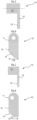
- FIGS. 5 and 6 illustrate a lock 10 with centered rotation: the body 11 of the lock is a hollow cylinder pierced with a cylindrical tube coaxial with the axis of the cylinder of the body, for the passage of the fixing means 104.
- the wing 12 of the lock can have a chamfer 13, for example at 45°, in order to facilitate its passage into the attachment cavity 77 and come into contact, or almost into contact, with the bottom 78.
- the wing here has a width 112 of 13.0 mm.
- the length between the axis of the lock and the end of the wing 12 is approximately 26 mm.
- the wing 12 here penetrates into the attachment cavity 77 over the entire internal height of the rail 75, i.e. over a height of approximately 7 mm.
- FIGS. 7 and 8 illustrate a lock 10 with eccentric rotation, identical to the previous one except that, for the passage of the fixing means 104, the body 11 is a hollow cylinder pierced with a cylindrical tube which is not coaxial with the axis of the cylinder of the body: the axis of the cylindrical tube is offset laterally relative to the longitudinal orientation of the wing 12.
- the lateral wing 12 is integral with the body 11.
- Figures 9 to 11 illustrate a third variant embodiment of the lock in which the wing 12 is separated from the body 11.
- This third variant makes it possible to maintain the wing 12 in an extended position along the application space 95, as visible in figure 9 , the time to introduce or remove the glazing 1 (for example if it has been broken during use of the means of transport) into or out of the bay 9.
- the inner pane 6 can itself be laminated.
Landscapes
- Engineering & Computer Science (AREA)
- Mechanical Engineering (AREA)
- Securing Of Glass Panes Or The Like (AREA)
- Bay Windows, Entrances, And Structural Adjustments Related Thereto (AREA)
Claims (10)
- Befestigungssystem einer seitlichen Verglasung (1) eines Transportmittels, insbesondere einer Zugverglasung, in einer umlaufenden Öffnung (9), das System umfassend eine Verglasung und eine umlaufende Öffnung (9);wobei die Verglasung eine feste Mehrfachverglasung ist,die eine Außenfläche (101), die einem Außenraum (E) gegenüberliegt, und eine Innenfläche (102), die einem Innenraum (I) gegenüberliegt, aufweist, wobei die Außenfläche (101) der Verglasung in eine Außenfläche (91) der Öffnung (9) über ihren gesamten Umfang optisch übergeht,die Verglasung (1) umfassend:- eine Außenfensterscheibe (2), die eine Außenfläche (21), die dem Außenraum (E) gegenüberliegt, und eine Umfangskante (20) aufweist, wobei die Außenfensterscheibe (2) vorzugsweise laminiert ist, und umfassend sodann mindestens eine Außenglasscheibe (3), eine Innenglasscheibe (5) sowie eine Kunststoffscheibe (4), die zwischen der Außenglasscheibe (3) und der Innenglasscheibe (5) angeordnet ist, wobei jede Scheibe (3, 4, 5) der Außenfensterscheibe (2) eine Umfangskante (30, 40, 50) aufweist,- eine Innenfensterscheibe (6), die eine Innenfläche (62), die dem Innenraum (I) gegenüberliegt, eine Zwischenfläche (61) gegenüber der Innenfläche sowie eine Umfangskante (60) aufweist,- eine Innenstruktur (7), die an dem Innenumfang der Außenfensterscheibe (2) und an dem Innenumfang der Innenfensterscheibe (6) angeordnet ist, wobei sie weiter zu der Mitte hin als zu der Umfangskante (20, 60) jeweils der Außenfensterscheibe (2) und der Innenfensterscheibe (6) liegt, und die diese zwei Fensterscheiben zusammenhält, sodass die Verglasung eine Trennung zwischen dem Außenraum und dem Innenraum mit einem Verglasungshohlraum (8) erzielt, der zwischen den Fensterscheiben (2, 6) angeordnet ist,- wobei die Innenstruktur (7) einen Aufhängehohlraum (77), der einen Zentripetalboden (78) und eine Zentrifugalöffnung (79) aufweist, vorweist, wobei die Öffnung (9) eine Innenseite (92) vorweist, die ein Befestigungsloch (93) aufweist, das zentrifugaler als die Kante (60) der Innenfensterscheibe (6) angeordnet ist, und eine Achse (A9) parallel zu der Kante (60) der Innenfensterscheibe (6) aufweist, wobei eine Verriegelung (10) an der Innenseite (92) durch ein Befestigungsmittel (104), das durch das Befestigungsloch (93) verläuft, befestigt ist, dadurch gekennzeichnet, dass die Verriegelung (10) einen seitlichen Flügel (12) aufweist, der sich in den Aufhängehohlraum (77) hinein und gegenüber einem Rand der Zwischenfläche (61) der Innenfensterscheibe (6) durch Drehung des seitlichen Flügels (12) um 90° erstreckt.
- System nach Anspruch 1, wobei der Aufhängehohlraum (77) durch eine lokalisierte Nut oder eine verlängerte Schiene (75) ausgebildet ist.
- System nach Anspruch 1 oder 2, wobei die Kante (20) der Außenfensterscheibe (2) oder die Kante (30) der Außenglasscheibe (3) an dem Zentrifugalüberhang (d) der Kante (60) der Innenfensterscheibe (6) entlang mindestens eines Teils der Länge der Kante (20, 30) der Außenfensterscheibe (2) oder der Außenglasscheibe (3) und vorzugsweise entlang der gesamten Länge der Kante (20, 30) der Außenfensterscheibe (2) oder der Außenglasscheibe (3) angeordnet ist.
- System nach Anspruch 3, wobei der Überhang (d) zwischen 5,0 und 30,0 mm und vorzugsweise zwischen 8,0 und 20,0 mm liegt.
- System nach einem der Ansprüche 1 bis 4, wobei die Kante (40) der Kunststoffscheibe (4) und/oder die Kante (50) der Innenglasscheibe (5) in Zentripetalrücksetzung (r) von der Kante (60) der Innenfensterscheibe (6) entlang mindestens eines Teils der Länge der Kante (40, 50) der Kunststoffscheibe (4) und/oder der Innenfensterscheibe (5) und vorzugsweise entlang der gesamten Länge der Kante (40, 50) der Kunststoffscheibe (4) und/oder der Innenfensterscheibe (5) angeordnet ist (oder sind).
- System nach Anspruch 5, wobei die Rücksetzung (r) zwischen 1,0 und 10,0 mm und vorzugsweise zwischen 2,0 und 8,0 mm liegt.
- System nach einem der Ansprüche 1 bis 6, wobei die Drehung exzentrisch ist, damit sich der Flügel (12) von der Achse (A9) des Befestigungslochs (93) während der Eindringungsbewegung des Flügels (12) in den Aufhängehohlraum (77) entfernt.
- System nach einem der Ansprüche 1 bis 7, wobei die Kante (20) der Außenfensterscheibe (2) oder die Kante (50) der Innenglasscheibe (5) eine Zentrifugallippe (73) aus Kunststoffmaterial vorweist.
- System nach einem der Ansprüche 1 bis 8, wobei eine Außenabdichtung (98) an dem Kontakt zwischen einerseits einem Rand der Außenfläche (91) der Öffnung (9) und andererseits der Kante (20) der Außenfensterscheibe (2) oder der Kante (30) der Außenglasscheibe (3) vorhanden ist, wobei die Außenabdichtung (98) vorzugsweise eine Höhe (h), die zwischen 5,0 und 30,0 mm und vorzugsweise zwischen 8,0 und 20,0 mm liegt, aufweist.
- System nach einem der Ansprüche 1 bis 9, wobei ein Innenabdichtungswulst (70) an dem Kontakt zwischen einerseits der Innenseite (92) der Öffnung (9) und andererseits der Innenfläche (62) der Innenfensterscheibe (6) vorhanden ist.
Applications Claiming Priority (2)
| Application Number | Priority Date | Filing Date | Title |
|---|---|---|---|
| FR2001340A FR3107027B1 (fr) | 2020-02-11 | 2020-02-11 | Systeme de fixation d’un vitrage lateral de moyen de transport avec un verrou |
| PCT/FR2021/050232 WO2021160962A1 (fr) | 2020-02-11 | 2021-02-09 | Systeme de fixation d'un vitrage lateral de moyen de transport avec un verrou |
Publications (2)
| Publication Number | Publication Date |
|---|---|
| EP4103442A1 EP4103442A1 (de) | 2022-12-21 |
| EP4103442B1 true EP4103442B1 (de) | 2025-02-19 |
Family
ID=70295411
Family Applications (1)
| Application Number | Title | Priority Date | Filing Date |
|---|---|---|---|
| EP21709070.3A Active EP4103442B1 (de) | 2020-02-11 | 2021-02-09 | System zum befestigen einer seitenverglasung eines transportmittels mit einem schloss |
Country Status (8)
| Country | Link |
|---|---|
| EP (1) | EP4103442B1 (de) |
| JP (1) | JP2023513301A (de) |
| KR (1) | KR20220137715A (de) |
| CN (1) | CN113544038B (de) |
| CA (1) | CA3166080A1 (de) |
| FR (1) | FR3107027B1 (de) |
| PL (1) | PL4103442T3 (de) |
| WO (1) | WO2021160962A1 (de) |
Families Citing this family (1)
| Publication number | Priority date | Publication date | Assignee | Title |
|---|---|---|---|---|
| FR3127161B1 (fr) * | 2021-09-17 | 2023-09-08 | Saint Gobain | Systeme de fixation d’un vitrage lateral de moyen de transport avec un verrou comprenant au moins une saillies de detrompage |
Family Cites Families (15)
| Publication number | Priority date | Publication date | Assignee | Title |
|---|---|---|---|---|
| US2256548A (en) * | 1938-12-08 | 1941-09-23 | Om Edwards Co Inc | Sash and sash attaching means |
| DE3301757C2 (de) * | 1983-01-20 | 1985-02-21 | Messerschmitt-Bölkow-Blohm GmbH, 8012 Ottobrunn | Fahrzeugfenster |
| DE4009348C2 (de) * | 1990-03-23 | 1995-02-02 | Cleff Gmbh Carl Wilhelm | Fahrzeugfenster, insbesondere für Reisezugwagen |
| JP2546515Y2 (ja) * | 1993-06-29 | 1997-09-03 | 川崎重工業株式会社 | 車両用窓の取付構造 |
| AT889U1 (de) * | 1994-08-03 | 1996-07-25 | Euromotive Gmbh | Vorrichtung zur befestigung eines fahrzeugfensters |
| DE19945876C2 (de) * | 1999-09-24 | 2002-05-16 | Deutsche Bahn Ag | Mehrscheiben-Isolierverglasung für Schienenfahrzeuge, insbesondere für Hochgeschwindigkeitszüge |
| JP3645874B2 (ja) * | 2002-08-20 | 2005-05-11 | 東急車輛製造株式会社 | 車両用二重窓構造 |
| CN103291181B (zh) * | 2013-05-21 | 2015-06-24 | 唐山轨道客车有限责任公司 | 铁道车辆用车窗及铁道车辆 |
| ITRG20130002A1 (it) * | 2013-06-27 | 2014-12-28 | Giuseppe Bracchitta | Profilato per serramenti ottenuto collegando tre elementi di diverso materiale con relativo metodo e dispositivo per la sua formazione realizzante la contemporanea ritenuta del vetro |
| FR3026076B1 (fr) * | 2014-09-19 | 2016-11-25 | Saint Gobain | Vitrage lateral de moyen de transport a fenetre ouvrable |
| FR3034041B1 (fr) | 2015-03-25 | 2021-07-23 | Saint Gobain | Vitrage lateral de moyen de transport a substrat issue de secours renforce |
| FR3040659B1 (fr) * | 2015-09-09 | 2017-10-06 | Saint Gobain | Vitrage lateral de moyen de transport a fixation par l’exterieur |
| ITUB20153763A1 (it) * | 2015-09-21 | 2017-03-21 | Gsg Int S P A | Anta per porte o finestre e serramento ottenuto con l'anta. |
| CN106347392A (zh) * | 2016-11-04 | 2017-01-25 | 中车青岛四方机车车辆股份有限公司 | 列车车窗结构及具有其的列车 |
| FR3081766B1 (fr) | 2018-05-31 | 2020-05-22 | Saint-Gobain Glass France | Vitrage lateral de moyen de transport issue de secours a verre exterieur presentant un retrait. |
-
2020
- 2020-02-11 FR FR2001340A patent/FR3107027B1/fr active Active
-
2021
- 2021-02-09 WO PCT/FR2021/050232 patent/WO2021160962A1/fr not_active Ceased
- 2021-02-09 PL PL21709070.3T patent/PL4103442T3/pl unknown
- 2021-02-09 CN CN202180001927.5A patent/CN113544038B/zh active Active
- 2021-02-09 JP JP2022548580A patent/JP2023513301A/ja active Pending
- 2021-02-09 CA CA3166080A patent/CA3166080A1/fr active Pending
- 2021-02-09 KR KR1020227030581A patent/KR20220137715A/ko active Pending
- 2021-02-09 EP EP21709070.3A patent/EP4103442B1/de active Active
Also Published As
| Publication number | Publication date |
|---|---|
| CA3166080A1 (fr) | 2021-08-19 |
| CN113544038B (zh) | 2024-10-29 |
| KR20220137715A (ko) | 2022-10-12 |
| FR3107027B1 (fr) | 2024-03-22 |
| PL4103442T3 (pl) | 2025-07-07 |
| WO2021160962A1 (fr) | 2021-08-19 |
| CN113544038A (zh) | 2021-10-22 |
| JP2023513301A (ja) | 2023-03-30 |
| FR3107027A1 (fr) | 2021-08-13 |
| EP4103442A1 (de) | 2022-12-21 |
Similar Documents
| Publication | Publication Date | Title |
|---|---|---|
| EP3802116B1 (de) | Als notausstieg verwendbares seitenfenster eines transportmittels mit einer zurückgesetzten äusseren glasscheibe | |
| EP3532287B1 (de) | Schiebeverbundglasscheibe mit innenseitigem überhang | |
| EP3532288B1 (de) | Schiebeverbundglasscheibe mit internem überhang | |
| EP4126627B1 (de) | System zum befestigen einer seitenverglasung eines transportmittels mit einem schloss | |
| EP4401996B1 (de) | System zur befestigung einer seitenverglasung eines transportmittels mit einem schloss mit mindestens einer verwechslungssicherungsprojektion | |
| EP3347218B1 (de) | Seitliche verglasung eines verkehrsmittels zur befestigung von aussen | |
| EP4103442B1 (de) | System zum befestigen einer seitenverglasung eines transportmittels mit einem schloss | |
| FR2619587A1 (fr) | Panneau de revetement ou de fenetre pour la surface exterieure d'une facade, et facade equipee d'un tel panneau | |
| FR2912180A1 (fr) | Chassis de porte ou fenetre a ouvrant coulissant comportant un montant vertical d'ouvrant cache. | |
| EP1052362A2 (de) | Doppelverglasung | |
| CA2924487A1 (fr) | Vitrage comportant une portion de joint a insert ferme et procede de fabrication dudit vitrage | |
| FR2665511A1 (fr) | Assemblages de profiles a discontinuite thermique, machine permettant de realiser de tels assemblages et structures composees de ces assemblages. | |
| EP4007695B1 (de) | Schiebeverbundglasscheibe mit internem seitenüberhang | |
| WO2023285516A1 (fr) | Vitrage feuillete coulissant lateralement, a debord interieur lateral protege et portiere laterale | |
| EP1553257B1 (de) | Panzertür oder -fenster mit einer direkt an der Panzerplatte verbundenen Verglasung | |
| CA3041870C (fr) | Vitrage feuillete coulissant a debord interieur | |
| FR2511071A1 (fr) | Procede de realisation d'un vitrage multiple, panneau vitre entrant dans la mise en oeuvre de ce procede, et profile faisant partie dudit panneau vitre | |
| FR3136406A1 (fr) | Vitrage comportant dans un coin un joint profile a decoupes et fente(s), joint et procede de fabrication d’un tel vitrage | |
| EP2003279A1 (de) | Klappfenster oder Ähnliches mit Rahmen, mit verdecktem Öffnungsflügel | |
| EP2224087A2 (de) | Rahmen für ein Fenster | |
| FR2776009A1 (fr) | Profile formant ossature de double vitrage | |
| FR3017410A1 (fr) | Element d'etancheite pour fenetre ou porte coulissante |
Legal Events
| Date | Code | Title | Description |
|---|---|---|---|
| STAA | Information on the status of an ep patent application or granted ep patent |
Free format text: STATUS: UNKNOWN |
|
| STAA | Information on the status of an ep patent application or granted ep patent |
Free format text: STATUS: THE INTERNATIONAL PUBLICATION HAS BEEN MADE |
|
| PUAI | Public reference made under article 153(3) epc to a published international application that has entered the european phase |
Free format text: ORIGINAL CODE: 0009012 |
|
| STAA | Information on the status of an ep patent application or granted ep patent |
Free format text: STATUS: REQUEST FOR EXAMINATION WAS MADE |
|
| 17P | Request for examination filed |
Effective date: 20220912 |
|
| AK | Designated contracting states |
Kind code of ref document: A1 Designated state(s): AL AT BE BG CH CY CZ DE DK EE ES FI FR GB GR HR HU IE IS IT LI LT LU LV MC MK MT NL NO PL PT RO RS SE SI SK SM TR |
|
| DAV | Request for validation of the european patent (deleted) | ||
| DAX | Request for extension of the european patent (deleted) | ||
| RIN1 | Information on inventor provided before grant (corrected) |
Inventor name: GASTAL, GUILLAUME |
|
| STAA | Information on the status of an ep patent application or granted ep patent |
Free format text: STATUS: EXAMINATION IS IN PROGRESS |
|
| 17Q | First examination report despatched |
Effective date: 20230920 |
|
| GRAP | Despatch of communication of intention to grant a patent |
Free format text: ORIGINAL CODE: EPIDOSNIGR1 |
|
| STAA | Information on the status of an ep patent application or granted ep patent |
Free format text: STATUS: GRANT OF PATENT IS INTENDED |
|
| INTG | Intention to grant announced |
Effective date: 20240912 |
|
| INTG | Intention to grant announced |
Effective date: 20240912 |
|
| GRAS | Grant fee paid |
Free format text: ORIGINAL CODE: EPIDOSNIGR3 |
|
| GRAA | (expected) grant |
Free format text: ORIGINAL CODE: 0009210 |
|
| STAA | Information on the status of an ep patent application or granted ep patent |
Free format text: STATUS: THE PATENT HAS BEEN GRANTED |
|
| AK | Designated contracting states |
Kind code of ref document: B1 Designated state(s): AL AT BE BG CH CY CZ DE DK EE ES FI FR GB GR HR HU IE IS IT LI LT LU LV MC MK MT NL NO PL PT RO RS SE SI SK SM TR |
|
| REG | Reference to a national code |
Ref country code: GB Ref legal event code: FG4D Free format text: NOT ENGLISH |
|
| REG | Reference to a national code |
Ref country code: CH Ref legal event code: EP |
|
| REG | Reference to a national code |
Ref country code: IE Ref legal event code: FG4D Free format text: LANGUAGE OF EP DOCUMENT: FRENCH |
|
| REG | Reference to a national code |
Ref country code: DE Ref legal event code: R096 Ref document number: 602021026347 Country of ref document: DE |
|
| REG | Reference to a national code |
Ref country code: DE Ref legal event code: R081 Ref document number: 602021026347 Country of ref document: DE Owner name: SAINT-GOBAIN SEKURIT FRANCE, FR Free format text: FORMER OWNER: SAINT-GOBAIN GLASS FRANCE, COURBEVOIE, FR |
|
| RAP2 | Party data changed (patent owner data changed or rights of a patent transferred) |
Owner name: SAINT-GOBAIN SEKURIT FRANCE |
|
| REG | Reference to a national code |
Ref country code: NL Ref legal event code: MP Effective date: 20250219 |
|
| PG25 | Lapsed in a contracting state [announced via postgrant information from national office to epo] |
Ref country code: RS Free format text: LAPSE BECAUSE OF FAILURE TO SUBMIT A TRANSLATION OF THE DESCRIPTION OR TO PAY THE FEE WITHIN THE PRESCRIBED TIME-LIMIT Effective date: 20250519 |
|
| PG25 | Lapsed in a contracting state [announced via postgrant information from national office to epo] |
Ref country code: FI Free format text: LAPSE BECAUSE OF FAILURE TO SUBMIT A TRANSLATION OF THE DESCRIPTION OR TO PAY THE FEE WITHIN THE PRESCRIBED TIME-LIMIT Effective date: 20250219 |
|
| PG25 | Lapsed in a contracting state [announced via postgrant information from national office to epo] |
Ref country code: ES Free format text: LAPSE BECAUSE OF FAILURE TO SUBMIT A TRANSLATION OF THE DESCRIPTION OR TO PAY THE FEE WITHIN THE PRESCRIBED TIME-LIMIT Effective date: 20250219 |
|
| REG | Reference to a national code |
Ref country code: LT Ref legal event code: MG9D |
|
| PG25 | Lapsed in a contracting state [announced via postgrant information from national office to epo] |
Ref country code: IS Free format text: LAPSE BECAUSE OF FAILURE TO SUBMIT A TRANSLATION OF THE DESCRIPTION OR TO PAY THE FEE WITHIN THE PRESCRIBED TIME-LIMIT Effective date: 20250619 Ref country code: NO Free format text: LAPSE BECAUSE OF FAILURE TO SUBMIT A TRANSLATION OF THE DESCRIPTION OR TO PAY THE FEE WITHIN THE PRESCRIBED TIME-LIMIT Effective date: 20250519 |
|
| PG25 | Lapsed in a contracting state [announced via postgrant information from national office to epo] |
Ref country code: NL Free format text: LAPSE BECAUSE OF FAILURE TO SUBMIT A TRANSLATION OF THE DESCRIPTION OR TO PAY THE FEE WITHIN THE PRESCRIBED TIME-LIMIT Effective date: 20250219 |
|
| PG25 | Lapsed in a contracting state [announced via postgrant information from national office to epo] |
Ref country code: HR Free format text: LAPSE BECAUSE OF FAILURE TO SUBMIT A TRANSLATION OF THE DESCRIPTION OR TO PAY THE FEE WITHIN THE PRESCRIBED TIME-LIMIT Effective date: 20250219 |
|
| PG25 | Lapsed in a contracting state [announced via postgrant information from national office to epo] |
Ref country code: LV Free format text: LAPSE BECAUSE OF FAILURE TO SUBMIT A TRANSLATION OF THE DESCRIPTION OR TO PAY THE FEE WITHIN THE PRESCRIBED TIME-LIMIT Effective date: 20250219 Ref country code: PT Free format text: LAPSE BECAUSE OF FAILURE TO SUBMIT A TRANSLATION OF THE DESCRIPTION OR TO PAY THE FEE WITHIN THE PRESCRIBED TIME-LIMIT Effective date: 20250620 |
|
| PG25 | Lapsed in a contracting state [announced via postgrant information from national office to epo] |
Ref country code: GR Free format text: LAPSE BECAUSE OF FAILURE TO SUBMIT A TRANSLATION OF THE DESCRIPTION OR TO PAY THE FEE WITHIN THE PRESCRIBED TIME-LIMIT Effective date: 20250520 Ref country code: BG Free format text: LAPSE BECAUSE OF FAILURE TO SUBMIT A TRANSLATION OF THE DESCRIPTION OR TO PAY THE FEE WITHIN THE PRESCRIBED TIME-LIMIT Effective date: 20250219 |
|
| REG | Reference to a national code |
Ref country code: GB Ref legal event code: 732E Free format text: REGISTERED BETWEEN 20250703 AND 20250709 |
|
| REG | Reference to a national code |
Ref country code: AT Ref legal event code: MK05 Ref document number: 1768042 Country of ref document: AT Kind code of ref document: T Effective date: 20250219 |
|
| PG25 | Lapsed in a contracting state [announced via postgrant information from national office to epo] |
Ref country code: SE Free format text: LAPSE BECAUSE OF FAILURE TO SUBMIT A TRANSLATION OF THE DESCRIPTION OR TO PAY THE FEE WITHIN THE PRESCRIBED TIME-LIMIT Effective date: 20250219 |
|
| PG25 | Lapsed in a contracting state [announced via postgrant information from national office to epo] |
Ref country code: SM Free format text: LAPSE BECAUSE OF FAILURE TO SUBMIT A TRANSLATION OF THE DESCRIPTION OR TO PAY THE FEE WITHIN THE PRESCRIBED TIME-LIMIT Effective date: 20250219 |
|
| PG25 | Lapsed in a contracting state [announced via postgrant information from national office to epo] |
Ref country code: DK Free format text: LAPSE BECAUSE OF FAILURE TO SUBMIT A TRANSLATION OF THE DESCRIPTION OR TO PAY THE FEE WITHIN THE PRESCRIBED TIME-LIMIT Effective date: 20250219 |
|
| PG25 | Lapsed in a contracting state [announced via postgrant information from national office to epo] |
Ref country code: AT Free format text: LAPSE BECAUSE OF FAILURE TO SUBMIT A TRANSLATION OF THE DESCRIPTION OR TO PAY THE FEE WITHIN THE PRESCRIBED TIME-LIMIT Effective date: 20250219 |
|
| PG25 | Lapsed in a contracting state [announced via postgrant information from national office to epo] |
Ref country code: CZ Free format text: LAPSE BECAUSE OF FAILURE TO SUBMIT A TRANSLATION OF THE DESCRIPTION OR TO PAY THE FEE WITHIN THE PRESCRIBED TIME-LIMIT Effective date: 20250219 Ref country code: EE Free format text: LAPSE BECAUSE OF FAILURE TO SUBMIT A TRANSLATION OF THE DESCRIPTION OR TO PAY THE FEE WITHIN THE PRESCRIBED TIME-LIMIT Effective date: 20250219 |
|
| PG25 | Lapsed in a contracting state [announced via postgrant information from national office to epo] |
Ref country code: RO Free format text: LAPSE BECAUSE OF FAILURE TO SUBMIT A TRANSLATION OF THE DESCRIPTION OR TO PAY THE FEE WITHIN THE PRESCRIBED TIME-LIMIT Effective date: 20250219 |
|
| PG25 | Lapsed in a contracting state [announced via postgrant information from national office to epo] |
Ref country code: SK Free format text: LAPSE BECAUSE OF FAILURE TO SUBMIT A TRANSLATION OF THE DESCRIPTION OR TO PAY THE FEE WITHIN THE PRESCRIBED TIME-LIMIT Effective date: 20250219 |
|
| REG | Reference to a national code |
Ref country code: DE Ref legal event code: R097 Ref document number: 602021026347 Country of ref document: DE |
|
| PLBE | No opposition filed within time limit |
Free format text: ORIGINAL CODE: 0009261 |
|
| STAA | Information on the status of an ep patent application or granted ep patent |
Free format text: STATUS: NO OPPOSITION FILED WITHIN TIME LIMIT |
|
| PGFP | Annual fee paid to national office [announced via postgrant information from national office to epo] |
Ref country code: GB Payment date: 20251218 Year of fee payment: 6 |
|
| PGFP | Annual fee paid to national office [announced via postgrant information from national office to epo] |
Ref country code: FR Payment date: 20251222 Year of fee payment: 6 |
|
| PGFP | Annual fee paid to national office [announced via postgrant information from national office to epo] |
Ref country code: PL Payment date: 20251227 Year of fee payment: 6 |
|
| 26N | No opposition filed |
Effective date: 20251120 |
|
| PGFP | Annual fee paid to national office [announced via postgrant information from national office to epo] |
Ref country code: DE Payment date: 20251224 Year of fee payment: 6 |
|
| PGFP | Annual fee paid to national office [announced via postgrant information from national office to epo] |
Ref country code: IT Payment date: 20260122 Year of fee payment: 6 |