EP4101309B1 - Maschine zum verarbeiten von flüssigen oder halbflüssigen lebensmitteln und verfahren zum verarbeiten einer lebensmittelgrundmischung in dieser maschine. - Google Patents
Maschine zum verarbeiten von flüssigen oder halbflüssigen lebensmitteln und verfahren zum verarbeiten einer lebensmittelgrundmischung in dieser maschine. Download PDFInfo
- Publication number
- EP4101309B1 EP4101309B1 EP22178052.1A EP22178052A EP4101309B1 EP 4101309 B1 EP4101309 B1 EP 4101309B1 EP 22178052 A EP22178052 A EP 22178052A EP 4101309 B1 EP4101309 B1 EP 4101309B1
- Authority
- EP
- European Patent Office
- Prior art keywords
- condenser
- heat exchanger
- exchanger fluid
- machine
- primary heat
- Prior art date
- Legal status (The legal status is an assumption and is not a legal conclusion. Google has not performed a legal analysis and makes no representation as to the accuracy of the status listed.)
- Active
Links
Images


Classifications
-
- A—HUMAN NECESSITIES
- A23—FOODS OR FOODSTUFFS; TREATMENT THEREOF, NOT COVERED BY OTHER CLASSES
- A23G—COCOA; COCOA PRODUCTS, e.g. CHOCOLATE; SUBSTITUTES FOR COCOA OR COCOA PRODUCTS; CONFECTIONERY; CHEWING GUM; ICE-CREAM; PREPARATION THEREOF
- A23G9/00—Frozen sweets, e.g. ice confectionery, ice-cream; Mixtures therefor
- A23G9/04—Production of frozen sweets, e.g. ice-cream
- A23G9/08—Batch production
- A23G9/12—Batch production using means for stirring the contents in a non-moving container
-
- A—HUMAN NECESSITIES
- A23—FOODS OR FOODSTUFFS; TREATMENT THEREOF, NOT COVERED BY OTHER CLASSES
- A23G—COCOA; COCOA PRODUCTS, e.g. CHOCOLATE; SUBSTITUTES FOR COCOA OR COCOA PRODUCTS; CONFECTIONERY; CHEWING GUM; ICE-CREAM; PREPARATION THEREOF
- A23G9/00—Frozen sweets, e.g. ice confectionery, ice-cream; Mixtures therefor
- A23G9/04—Production of frozen sweets, e.g. ice-cream
- A23G9/045—Production of frozen sweets, e.g. ice-cream of slush-ice, e.g. semi-frozen beverage
-
- A—HUMAN NECESSITIES
- A23—FOODS OR FOODSTUFFS; TREATMENT THEREOF, NOT COVERED BY OTHER CLASSES
- A23G—COCOA; COCOA PRODUCTS, e.g. CHOCOLATE; SUBSTITUTES FOR COCOA OR COCOA PRODUCTS; CONFECTIONERY; CHEWING GUM; ICE-CREAM; PREPARATION THEREOF
- A23G9/00—Frozen sweets, e.g. ice confectionery, ice-cream; Mixtures therefor
- A23G9/04—Production of frozen sweets, e.g. ice-cream
- A23G9/22—Details, component parts or accessories of apparatus insofar as not peculiar to a single one of the preceding groups
- A23G9/225—Ice-cream freezing and storing cabinets
-
- A—HUMAN NECESSITIES
- A23—FOODS OR FOODSTUFFS; TREATMENT THEREOF, NOT COVERED BY OTHER CLASSES
- A23G—COCOA; COCOA PRODUCTS, e.g. CHOCOLATE; SUBSTITUTES FOR COCOA OR COCOA PRODUCTS; CONFECTIONERY; CHEWING GUM; ICE-CREAM; PREPARATION THEREOF
- A23G9/00—Frozen sweets, e.g. ice confectionery, ice-cream; Mixtures therefor
- A23G9/04—Production of frozen sweets, e.g. ice-cream
- A23G9/22—Details, component parts or accessories of apparatus insofar as not peculiar to a single one of the preceding groups
- A23G9/228—Arrangement and mounting of control or safety devices
-
- A—HUMAN NECESSITIES
- A23—FOODS OR FOODSTUFFS; TREATMENT THEREOF, NOT COVERED BY OTHER CLASSES
- A23G—COCOA; COCOA PRODUCTS, e.g. CHOCOLATE; SUBSTITUTES FOR COCOA OR COCOA PRODUCTS; CONFECTIONERY; CHEWING GUM; ICE-CREAM; PREPARATION THEREOF
- A23G9/00—Frozen sweets, e.g. ice confectionery, ice-cream; Mixtures therefor
- A23G9/04—Production of frozen sweets, e.g. ice-cream
- A23G9/22—Details, component parts or accessories of apparatus insofar as not peculiar to a single one of the preceding groups
- A23G9/28—Details, component parts or accessories of apparatus insofar as not peculiar to a single one of the preceding groups for portioning or dispensing
- A23G9/281—Details, component parts or accessories of apparatus insofar as not peculiar to a single one of the preceding groups for portioning or dispensing at the discharge end of freezing chambers
-
- F—MECHANICAL ENGINEERING; LIGHTING; HEATING; WEAPONS; BLASTING
- F25—REFRIGERATION OR COOLING; COMBINED HEATING AND REFRIGERATION SYSTEMS; HEAT PUMP SYSTEMS; MANUFACTURE OR STORAGE OF ICE; LIQUEFACTION SOLIDIFICATION OF GASES
- F25B—REFRIGERATION MACHINES, PLANTS OR SYSTEMS; COMBINED HEATING AND REFRIGERATION SYSTEMS; HEAT PUMP SYSTEMS
- F25B39/00—Evaporators; Condensers
- F25B39/02—Evaporators
-
- F—MECHANICAL ENGINEERING; LIGHTING; HEATING; WEAPONS; BLASTING
- F25—REFRIGERATION OR COOLING; COMBINED HEATING AND REFRIGERATION SYSTEMS; HEAT PUMP SYSTEMS; MANUFACTURE OR STORAGE OF ICE; LIQUEFACTION SOLIDIFICATION OF GASES
- F25B—REFRIGERATION MACHINES, PLANTS OR SYSTEMS; COMBINED HEATING AND REFRIGERATION SYSTEMS; HEAT PUMP SYSTEMS
- F25B39/00—Evaporators; Condensers
- F25B39/04—Condensers
-
- F—MECHANICAL ENGINEERING; LIGHTING; HEATING; WEAPONS; BLASTING
- F25—REFRIGERATION OR COOLING; COMBINED HEATING AND REFRIGERATION SYSTEMS; HEAT PUMP SYSTEMS; MANUFACTURE OR STORAGE OF ICE; LIQUEFACTION SOLIDIFICATION OF GASES
- F25B—REFRIGERATION MACHINES, PLANTS OR SYSTEMS; COMBINED HEATING AND REFRIGERATION SYSTEMS; HEAT PUMP SYSTEMS
- F25B41/00—Fluid-circulation arrangements
- F25B41/40—Fluid line arrangements
-
- F—MECHANICAL ENGINEERING; LIGHTING; HEATING; WEAPONS; BLASTING
- F25—REFRIGERATION OR COOLING; COMBINED HEATING AND REFRIGERATION SYSTEMS; HEAT PUMP SYSTEMS; MANUFACTURE OR STORAGE OF ICE; LIQUEFACTION SOLIDIFICATION OF GASES
- F25B—REFRIGERATION MACHINES, PLANTS OR SYSTEMS; COMBINED HEATING AND REFRIGERATION SYSTEMS; HEAT PUMP SYSTEMS
- F25B49/00—Arrangement or mounting of control or safety devices
- F25B49/02—Arrangement or mounting of control or safety devices for compression type machines, plants or systems
-
- F—MECHANICAL ENGINEERING; LIGHTING; HEATING; WEAPONS; BLASTING
- F25—REFRIGERATION OR COOLING; COMBINED HEATING AND REFRIGERATION SYSTEMS; HEAT PUMP SYSTEMS; MANUFACTURE OR STORAGE OF ICE; LIQUEFACTION SOLIDIFICATION OF GASES
- F25B—REFRIGERATION MACHINES, PLANTS OR SYSTEMS; COMBINED HEATING AND REFRIGERATION SYSTEMS; HEAT PUMP SYSTEMS
- F25B6/00—Compression machines, plants or systems, with several condenser circuits
- F25B6/02—Compression machines, plants or systems, with several condenser circuits arranged in parallel
-
- F—MECHANICAL ENGINEERING; LIGHTING; HEATING; WEAPONS; BLASTING
- F25—REFRIGERATION OR COOLING; COMBINED HEATING AND REFRIGERATION SYSTEMS; HEAT PUMP SYSTEMS; MANUFACTURE OR STORAGE OF ICE; LIQUEFACTION SOLIDIFICATION OF GASES
- F25B—REFRIGERATION MACHINES, PLANTS OR SYSTEMS; COMBINED HEATING AND REFRIGERATION SYSTEMS; HEAT PUMP SYSTEMS
- F25B2700/00—Sensing or detecting of parameters; Sensors therefor
- F25B2700/21—Temperatures
Definitions
- This invention relates to a machine for processing liquid or semi-liquid food products, in particular a machine for the thermal treatment of the products, and a method for food processing a base food mixture in said machine. More specifically, this invention relates to an apparatus such as a batch freezer, a pasteurizer, a crushed-ice drink maker, etc.
- Said machines comprise a product containing element in which the product is contained and stirred with a stirrer. These machines also comprise a refrigeration system integrated in the machine to allow thermally processing the product to be dispensed.
- the refrigeration system comprises a compressor, which increases the pressure of the heat exchanger fluid, a heat exchanger, which draws heat from the heat exchanger fluid, exchanging it with the outside environment, an element for reducing the pressure (for example, a throttle valve) which reduces the pressure of the heat exchanger fluid and an evaporator which draws heat from the product to be dispensed to transfer it to the heat exchanger fluid.
- a compressor which increases the pressure of the heat exchanger fluid
- a heat exchanger which draws heat from the heat exchanger fluid, exchanging it with the outside environment
- an element for reducing the pressure for example, a throttle valve
- an evaporator which draws heat from the product to be dispensed to transfer it to the heat exchanger fluid.
- the cooling capacity of the refrigeration system is influenced by the temperature of the ambient surroundings.
- the heat exchanger would be able to exchange a reduced quantity of heat with the outside environment at the evaporator.
- the refrigeration systems generally comprise a fan or a turbine with the heat exchanger in order to cool it.
- the heat exchangers made in this way are referred to as air condensers.
- the fan (or turbine) in the air condensers guarantees the operation of the machine, allowing the heat exchange between the heat exchanger fluid and the air.
- the air condensers may have several drawbacks linked especially with high temperature conditions of the outside environment.
- Document US10952456 shows a machine for processing liquid or semi-liquid food products including a containing element for containing the product to be dispensed; a stirrer for stirring the product to be dispensed; a heat exchanger fluid flowing in a circuit in a direction of circulation through an evaporator, a compressor, a condenser and a pressure reducing element; a fan rotating about an axis of rotation to force an air flow towards the condenser; a control unit connected to the fan to control the fan through a speed signal; a temperature sensor, located downstream of the condenser in the circulation direction to detect a condensation temperature and configured to send to the control unit a temperature signal as a function of which the control unit generates the speed signal.
- Document EP3360421 shows a machine for making and dispensing cold or ice beverages, such as cool drinks, slushes, sorbets and the like, comprising at least: a containment and processing tank for the product to be dispensed which has a front wall, which is equipped at the bottom of it with a dispensing mouth for dispensing the beverage, a dispenser, located at the beverage dispensing mouth and able to be turned on or off to allow the beverage to be dispensed; a thermal treatment cylinder located inside the containment tank; a stirrer located outside an outer surface of said thermal treatment cylinder and adapted to rotate about a respective axis of rotation; a refrigerating plant comprising a first exchanger, a second heat exchanger, a pressure reducing unit and a compressor, the first heat exchanger being located inside said thermal treatment cylinder, a containment compartment for the second heat exchanger, a pressure reducing unit and a compressor.
- a further drawback is represented by the heat released by the air condenser into the room where the cooling machine is situated.
- the aim of the invention is to provide a machine for processing liquid and semi-liquid food products which overcomes the above-mentioned drawbacks of the prior art and a method for food processing in said machine.
- the aim of this disclosure is to provide a machine for processing liquid and semi-liquid food products which is capable of functioning efficiently under all ambient conditions.
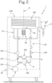
- the numeral 1 denotes a machine for making and dispensing liquid or semi-liquid food products according to this invention.
- the machine 1 may allow the production of different types of liquid or semi-liquid products, such as, for example, ice creams, sorbets, yogurts, custards, etc.
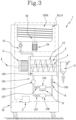
- the machine 1 comprises:
- the primary heat exchanger fluid passes through the closed circuit 101 in the following order: the evaporator 102, the compressor 103; the at least one first air condenser 104 and the throttle element 105.
- the machine 1 further comprises a control unit U.
- the refrigeration system 100 of the machine 1 further comprises, according to the invention:
- control unit U is configured to drive the regulating means 107 in such a way as to regulate the flow of primary heat exchanger fluid in the first and in the second condenser 104, 106 as a function of an operating parameter O of the machine 1.
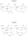
- the regulating means 107 are shown in Figures 1 , 2 , 3 , 4 with a "butterfly" symbol and in Figures 5, 6 , 7, 8 with a small circle.
- the primary heat exchanger fluid passes in succession: the evaporator 102, the compressor 103; the at least one first air condenser 104 and the throttle element 105.
- the expression “upstream” means everything that precedes, in the circuit, a predetermined point/element; the expression “downstream” means all that follows, in the circuit, a predetermined point/element.
- regulating means is used to mean elements which allow the flow of the primary heat exchanger fluid to be varied (continuously, discretely, or of the ON-OFF type, that is, between two end values of zero flow and maximum flow).
- the regulating means 107 are located upstream of the first condenser 104.
- the regulating means 107 are located downstream of the first condenser 104.
- the regulating means 107 are located upstream of the first condenser 106.
- the regulating means 107 are located downstream of the second condenser 106.
- the regulating means 107 are located upstream of both the first condenser 104 and the second condenser 106.
- the regulating means 107 are located downstream of both the first condenser 104 and the second condenser 106.
- the regulating means 107 comprise at least one two-way valve.
- the regulating means 107 comprise at least one three-way valve.
- the regulating means 107 make it possible to operate the refrigeration system 100 in three different ways:
- the evaporator 102 is operatively coupled to the container 2, thus allowing heat to be exchanged between the primary heat exchanger fluid and the product being processed inside the container 2.
- the evaporator 102 and the containing element 2 have a partition wall 12 in common.
- the partition wall 12 has a surface in contact with the primary heat exchanger fluid and a further surface in contact with the product to be dispensed.
- the walls of the container 2 since they are closest to the evaporator 102, are subject to possible formation of ice.
- the stirrer 4 has blades designed to prevent formation of ice on the inside surface of the container 2; in effect, during rotation of the stirrer 4, the blades are designed to scrape the inside surface of the container 2.
- the stirrer 4 is a screw feeder.
- the first air condenser 104 comprises a fan 9.
- the first condenser 104 also comprises a finned structure, coupled to the closed circuit 101, designed to allow the heat exchange surface between the primary heat exchanger fluid and the surrounding air to be increased.
- the fan 9 is rotated by an electric motor (not illustrated).
- the purpose of the fan 9 is to cool the primary heat exchanger fluid which passes through the first condenser 104 allowing said primary heat exchanger fluid to increase the quantity of heat exchanged with the environment.
- the refrigeration system 100 of the machine 1 comprises a second condenser 106 operating with a secondary heat exchanger fluid (for example, water or a mixture of water).
- a secondary heat exchanger fluid for example, water or a mixture of water.
- This type of condenser allows the heat exchange to occur between primary heat exchanger fluid and secondary heat exchanger fluid.
- the heat exchange between the primary heat exchanger fluid and the secondary heat exchanger fluid occurs without direct contact between the two since they flow inside separate circuits.
- the primary heat exchanger fluid and the secondary heat exchanger fluid may be in the same current or counter-current.
- the second condenser 106 is a plate heat exchanger.
- the second condenser 106 is a shell heat exchanger.
- the second condenser 106 is a concentric tube heat exchanger.
- the secondary heat exchanger fluid used in the second condenser 106 may flow in a secondary circuit 201 (illustrated in Figure 4 ) so as to be recirculated and cooled to continue to be able to exchange heat with the primary heat exchanger fluid of the closed circuit 101.
- the second condenser 106 may be coupled to at least one cooling tower 202 (with natural circulation or forced circulation, that is to say, provided with fans to favour the heat exchange between the secondary heat exchanger fluid and the surrounding air).
- the use of a condenser operating with a secondary heat exchanger fluid guarantees a better thermodynamic efficiency with respect to only use of an air condenser.
- a second condenser 106 operating with a secondary heat exchanger fluid significantly reduces the noise due to the fan of the air condensers, especially when the fan operates in overload conditions.
- control unit U is connected (to command and/or control) with one or more of the following components of the machine 1:
- the control unit U is programmed to generate, receive and process control signals.
- the control unit U is programmed to generate drive signals as a function of the control signals.
- the control unit U is programmed to send said control signals to the components of the machine 1 to which the control unit U is connected and which is designed to control.
- control unit U is configured to rotate the stirrer 4 about the mixing axis A by controlling the actuator 5.
- the actuator 5 is an electric motor.
- the control unit U is configured to drive the regulating means 107 in such a way as to regulate the flow of primary heat exchanger fluid in the first and in the second condenser 104, 106 as a function of an operating parameter O of the machine 1.
- operating parameter is used to mean any machine state or operating parameter which can be associated with processing (for example a parameter relating to the state of components, ingredients and/or products).
- the operating parameter is a parameter relating to the state of the ingredients and/or of the products or, alternatively, a parameter relating to the state of the refrigeration system (preferably the state of the primary heat exchanger fluid at one or more points of the system).
- the control unit U allows, depending on the operating parameter O, the control of the machine 1 in an optimum manner.
- the control unit U may, according to an aspect, be configured for regulating the speed of rotation of the fan 9 of the first air condenser 104 as a function of the operating parameter O.
- control unit U is configured to drive the regulating means 107 in such a way as to allow the primary heat exchanger fluid to flow in the first condenser 104 and/or in the second condenser 106 as a function of the type of product.
- the machine 1 comprises a user interface 16.
- the user interface 16 is connected to the control unit U to allow a user to enter the value of the operating parameter O (relating to the state of components, ingredients and/or products).
- the user interface 16 connected to the control unit U allows the type of product to be inserted so as to consequently regulate the regulating means 107.
- the machine 1 comprises at least one sensor 6 by means of which it is able to measure the operating parameter O.
- detecting the operating parameter O by means of the sensor 6 makes it possible to keep the machine 1 monitored.
- Another advantage of detecting the operating parameter O by means of the sensor 6 is that of making the control of the machine 1 automated.
- the operating parameter O detected by the sensor 6 may be:
- the machine 1 comprises at least two sensors 6 designed to measure different operating parameters O.
- control unit U is configured to drive the regulating means 107 in such a way as to allow the primary heat exchanger fluid to flow only in the first condenser 104 if the temperature or the pressure detected by the sensor 6 is less than a first predetermined value.
- the first predetermined value is a temperature value
- the first predetermined value is between 25°C and 35°C.
- the first predetermined value is a temperature value
- the first predetermined value is between 27.5°C and 32.5°C (preferably 30°C).
- activating only the first condenser 104 if the temperature or the pressure detected is less than the first predetermined value guarantees that the refrigeration to operate in an optimum manner.
- the first condenser 104 has a lower energy consumption than the second condenser 106.
- control unit U is configured to drive the regulating means 107 in such a way as to allow the primary heat exchanger fluid to flow only in the first condenser 106 if the temperature or the pressure detected by the sensor 6 is less than a first predetermined value.
- the second predetermined value is a temperature value
- the second predetermined value is between 35°C and 45°C.
- the second predetermined value is a temperature value
- the second predetermined value is between 37.5°C and 42.5°C (preferably 40°C).
- activating only the second condenser 106 if the temperature detected is greater than the second predetermined value guarantees that the refrigeration system operates in an optimum manner, because the second condenser 106, having a thermal efficiency greater than that of the first condenser 104, allows a more efficient heat exchange in these conditions.
- control unit U is configured to drive the regulating means 107, so as to choke (that is, subdivide) the primary heat exchanger fluid in the first condenser 104 and in the second condenser 106 if the temperature detected by the sensor 6 is greater than or equal to the first predetermined value and less than or equal to the second predetermined value.
- the choking is a function of the temperature: in effect, if the temperature detected by the sensor 6 is greater than or equal to the first predetermined value and less than or equal to the second predetermined value, the control unit U is configured to control the regulating means 107, so as to choke (that is, divide) the flow of primary heat exchanger fluid in the first condenser 104 and in the second condenser 106 according to a proportion equal to a difference between the temperature/pressure value detected by the sensor 6 and the first predetermined temperature/pressure value divided by the difference between the second and the first predetermined temperature/pressure value.
- the regulating means 107 allow a flow of primary heat exchanger fluid entering the second condenser 106 proportional to the temperature or pressure detected by the sensor 6.
- the regulating means 107 are configured so as to regulate the flow of primary heat exchanger fluid in the first and in the second condenser (104, 106) as a function of the pressure value detected as follows:
- the primary heat exchanger fluid is an HFO coolant such as R-452A
- the first pressure value is 23 bar (2.3 MPa) and the second pressure value is 19 bar (1.9 MPa)
- the first and the second pressure values may be different from those indicated.
- control unit U is configured to drive the regulating means 107 in such a way as to allow the primary heat exchanger fluid to flow in the first condenser 104 and/or in the second condenser 106 as a function of the type of product.
- the senor 6 detects the type of product processed by the machine 1 so as to consequently regulate the regulating means 107.
- the type of product is introduced (that is, communicated to the control unit U) by means of a user interface 16.
- regulating the flow of primary heat exchanger fluid in the first condenser 104 and/or in the second condenser 106 as a function of the type of product guarantees the optimum characteristics for the desired product are obtained; in effect, it is possible to use - in advance - actively in the refrigeration system the first condenser 104 and/or the second condenser 106 on the basis of the characteristics and specific features of the product being processed.
- control unit U is configured to drive the regulating means 107 in such a way as to allow the primary heat exchanger fluid to flow in the first condenser 104 and/or in the second condenser 106 as a function of the step in the operation of the machine 1.
- operating step means the processing time and/or the type of processing being performed on the finished product.
- operating step may mean the mixing step, the mixing and cooling step (simultaneously), etc...
- the second condenser 106 is disposed parallel to the first air condenser 104.
- the configuration in parallel of the first and second condensers 104, 106 allows the two condensers to be simultaneously activated in the presence of predetermined operating conditions and to exchange the heat necessary to guarantee the optimum operation of the refrigeration system.
- the closed circuit 101 comprises a first leg 7 and a second leg 8.
- the first condenser 104 is positioned in the first leg 7.
- the second condenser 106 is positioned in the second leg 8.
- the first leg 7 is positioned in parallel to the second leg 8.
- the first leg 7 is positioned in series with the second leg 8.
- the closed circuit 101 in the configuration in series of the leg 7 and of the leg 8, comprises a first bypass leg 10 (associated with the leg 7) which allows the primary heat exchanger fluid to pass beyond the first condenser 104 allowing the flow solely in the second condenser 106.
- the closed circuit 101 in the configuration in series of the leg 7 and of the leg 8, comprises the first bypass leg 10 which allows the primary heat exchanger fluid to pass beyond the first condenser 104 and a second bypass leg 11 (associated with the leg 8) which allows the primary heat exchanger fluid to pass beyond the second condenser 106.
- the closed circuit 101 in the configuration in series of the leg 7 and of the leg 8, comprises the second bypass leg 11 which allows the primary heat exchanger fluid to pass beyond the second condenser 106.
- the regulating means 107 comprise at least one valve which allows regulating the flow of primary heat exchanger fluid in the first condenser 104 and/or in the second condenser 106.
- the regulating means 107 comprise at least one two-way and/or three-way valve.
- two-way valve means a valve provided with a valve body (with an inlet and an outlet) and a shutter, the movement of which regulates the internal passageway and chokes the flow of the primary heat exchanger fluid through it.
- three-way valve means a valve provided with a valve body and a shutter which regulates the flow of the primary heat exchanger fluid inside it. These three-way valves may be partly open or closed and be provided with an inlet and two outlets or with two inlets and an outlet.
- the regulating means 107 comprise a three-way valve v1 positioned upstream or downstream (not illustrated) of the first condenser 104 and a three-way valve v2 upstream or downstream (not illustrated) of the second condenser 106.
- the regulating means 107 comprise a two-way valve v3 positioned on the first leg 7 upstream or downstream (not illustrated) of the first condenser 104, a two-way valve v4 on the first bypass leg 10, a two-way valve v5 positioned on the second leg 8 upstream or downstream (not illustrated) of the second condenser 106, a two-way valve v6 on the second bypass leg 11.
- the regulating means 107 comprise a three-way valve positioned upstream or downstream of the first condenser 104, a two-way valve positioned on the second leg 8 upstream or downstream of the second condenser 106 and a two-way valve on the second bypass leg 11.
- the regulating means 107 comprise a two-way valve positioned on the first leg 7 upstream or downstream of the first condenser 104, a two-way valve on the first bypass leg 10 and a three-way valve upstream or downstream of the second condenser 106.
- the regulating means 107 comprise a three-way valve v1 upstream (illustrated in Figure 7 ) or downstream (not illustrated) of the first and second condensers (104, 106).
- the regulating means 107 comprise a two-way valve v3 on the first leg 7 and a two-way valve v5 on the second leg 8, positioned upstream (illustrated in Figure 8 ) or downstream (not illustrated) of the first condenser 104 and of the second condenser 106, respectively.
- the container 2 is a thermal treatment tank 2A.
- the machine 1 comprises a dispensing duct 13.
- the dispensing duct 13 is configured to connect the thermal treatment tank 2A to the dispenser 3.
- the machine 1 comprises a further container 14.
- the further container 14 is connected to the container 2 by a filling duct 15.
- the further container 14 is in contact with the further evaporator 102A.
- the machine 1 comprises a second actuator 5A.
- the machine 1 comprises a second stirrer 4A.
- the second actuator 5A is connected to the second stirrer 4A for rotating it and mixing a product contained in the further container 14.
- the machine 1 preferably also comprises a pump for transferring the product from the further container 14' to the container 2.
- the control unit U is configured for rotating the second stirrer 4A about the further mixing axis B by controlling the second actuator 5A.
- a method is also defined for food processing of a food mixture, in particular a pasteurizing method.
- the method comprises a step of preparing a base mixture.
- the method comprises a step of heating a base mixture (preferably inside the container 2 and/or the thermal treatment tank 2A) for a predetermined heating time.
- the heating occurs at 60°C and 85°C; preferably, said heating time is greater than or equal to 30 minutes.
- the step of heating a base mixture comprises an alternating heating between the container 2 and the thermal treatment tank 2A.
- the method comprises a step of cooling said base mixture subjected to the rest step (preferably inside the container 2 and/or the thermal treatment tank 2A).
- the base mixture is cooled to a temperature of between 2°C and 6°C.
- the first heat exchanger fluid is made to flow in the second condenser 106.
- the first heat exchanger fluid flows in the second condenser 106.
- the first heat exchanger fluid starts to flow in the second condenser 106 before the step of cooling the base mixture.
- the flow of the first heat exchanger fluid inside the second condenser 106 is interrupted when the base mixture reaches the desired temperature.
- the second condenser 106 is used, having a greater effectiveness.
- the regulating means 107 regulate the flow of primary heat exchanger fluid in the first and in the second condensers (104, 106) as a function of the time step of the processing.
Landscapes
- Engineering & Computer Science (AREA)
- Life Sciences & Earth Sciences (AREA)
- Chemical & Material Sciences (AREA)
- Food Science & Technology (AREA)
- Polymers & Plastics (AREA)
- Physics & Mathematics (AREA)
- Mechanical Engineering (AREA)
- Thermal Sciences (AREA)
- General Engineering & Computer Science (AREA)
- Manufacturing & Machinery (AREA)
- Confectionery (AREA)
Claims (16)
- Maschine (1) zum Verarbeiten von flüssigen oder halbflüssigen Nahrungsmittelprodukten, umfassend:- einen Behälter (2) zum Enthalten des auszugebenden Produkts, der mit einer Ausgabevorrichtung (3) für das Produkt versehen ist;- ein Rührwerk (4), das sich im Behälter (2) befindet, wobei sich das Rührwerk (4) um eine Mischachse (A) zum Vermischen des auszugebenden Produkts dreht;- einen Steller (5), der mit dem Rührwerk (4) verbunden ist, um das Rührwerk (4) um die Mischachse (M) in Drehung zu versetzen;- ein Kühlsystem (100), umfassend einen geschlossenen Kreislauf (101), der ausgelegt ist, um ein Hauptwärmeüberträgermedium zu zirkulieren, einen Verdampfer (102), der mit dem Behälter (2) assoziiert ist, einen Verdichter (103), mindestens einen ersten Luftkondensator (104) und ein Drosselelement (105), wobei das Hauptwärmeüberträgermedium entlang des geschlossenen Kreislaufs (101) der Reihe nach durch Folgendes strömt: den Verdampfer (102), den Verdichter (103), den mindestens einen Luftkondensator (104) und das Drosselelement (105);- eine Steuereinheit (U), wobei die Maschine (1) dadurch gekennzeichnet ist, dass das Kühlsystem (100) zudem Folgendes umfasst:Regulierungsmittel (107) zum Regulieren des Stroms des Hauptwärmeüberträgermediums, die auf dem ersten Kondensator (104) und dem zweiten Kondensator (106) arbeiten, um den Mediumstrom jeweils im ersten Kondensator (104) und im zweiten Kondensator (106) zu regulieren, und dadurch, dass die Steuereinheit (U) ausgelegt ist, um die Regulierungsmittel (107) zu steuern, sodass der Strom des ersten Wärmeüberträgermediums im ersten und im zweiten Kondensator (104, 106) als eine Funktion eines Betriebsparameters (O) der Maschine (1) reguliert wird, wobei das Hauptwärmeüberträgermedium und das Nebenwärmeüberträgermedium in zwei separaten Kreisläufen strömen.- mindestens einen zweiten Kondensator (106), in dem das Hauptwärmeüberträgermedium und ein Nebenwärmeüberträgermedium strömen und der ausgelegt ist, um den Wärmetausch zwischen dem Hauptwärmeüberträgermedium und dem Nebenwärmeüberträgermedium zu erlauben, wobei sich der zweite Kondensator (106) stromabwärts des Verdichters (103) befindet;
- Maschine (1) nach Anspruch 1, umfassend einen Sensor (6), der ausgelegt ist, um den Betriebsparameter (O) der Maschine (1) zu erkennen.
- Maschine (1) nach Anspruch 2, wobei der Sensor (6) ausgelegt ist, um mindestens einen der folgenden Betriebsparameter (O) der Maschine (1) zu erkennen: die Temperatur des Hauptwärmeüberträgermediums stromaufwärts des Drosselelements (105); die Umgebungstemperatur; die Produkttemperatur; die Temperatur des Hauptwärmeüberträgermediums stromabwärts des Verdichters (103); die Temperatur des Hauptwärmeüberträgermediums stromaufwärts des Verdampfers (102) und die Temperatur des Hauptwärmeüberträgermediums stromabwärts des Verdampfers (102).
- Maschine (1) nach Anspruch 2, wobei der Sensor (6) ausgelegt ist, um mindestens einen der folgenden Betriebsparameter (O) der Maschine (1) zu erkennen: den Druck des Hauptwärmeüberträgermediums stromaufwärts des Drosselelements (105); den Druck des Hauptwärmeüberträgermediums stromabwärts des Verdichters (103); den Druck des Hauptwärmeüberträgermediums stromaufwärts des Verdampfers (102) und den Druck des Hauptwärmeüberträgermediums stromabwärts des Verdampfers (102).
- Maschine (1) nach Anspruch 3 oder 4, wobei die Steuereinheit (U) ausgelegt ist, um die Regulierungsmittel (107) so zu steuern, dass dem Hauptwärmeüberträgermedium nur erlaubt wird, in den ersten Kondensator (104) zu strömen, wenn die Temperatur oder der Druck, die bzw. der vom Sensor (6) erkannt wird, kleiner als ein erster vorgegebener Wert ist.
- Maschine (1) nach einem der Ansprüche 3 bis 5, wobei die Steuereinheit (U) ausgelegt ist, um die Regulierungsmittel (107) so zu steuern, dass dem Hauptwärmeüberträgermedium nur erlaubt wird, in den zweiten Kondensator (106) zu strömen, wenn die Temperatur oder der Druck, die bzw. der vom Sensor (6) erkannt wird, größer als ein zweiter vorgegebener Wert ist.
- Maschine (1) nach Anspruch 5 und 6, wobei die Steuereinheit (U) ausgelegt ist, um die Regulierungsmittel (107) so zu steuern, dass dem Hauptwärmeüberträgermedium erlaubt wird, in den ersten Kondensator (104) und in den zweiten Kondensator (106) zu strömen, wenn die Temperatur oder der Druck, die bzw. der vom Sensor (6) erkannt wird, größer oder gleich dem ersten vorgegebenen Wert ist und wenn die Temperatur oder der Druck, die bzw. der vom Sensor (6) erkannt wird, kleiner oder gleich dem zweiten vorgegebenen Wert ist.
- Maschine (1) nach Anspruch 7, wobei die Regulierungsmittel (107) dem Hauptwärmeüberträgermedium erlauben, proportional zur Temperatur oder zum Druck, die bzw. der vom Sensor (6) erkannt wird, in den zweiten Kondensator (106) zu strömen.
- Maschine (1) nach einem der vorhergehenden Ansprüche, wobei die Steuereinheit (U) ausgelegt ist, um die Regulierungsmittel (107) so zu steuern, dass dem Hauptwärmeüberträgermedium als eine Funktion des Produkttyps erlaubt wird, in den ersten Kondensator (104) und/oder in den zweiten Kondensator (106) zu strömen.
- Maschine (1) nach einem der vorhergehenden Ansprüche, wobei die Steuereinheit (U) ausgelegt ist, um die Regulierungsmittel (107) so zu steuern, dass dem Hauptwärmeüberträgermedium als eine Funktion des Schritts im Betrieb der Maschine (1) erlaubt wird, in den ersten Kondensator (104) und/oder in den zweiten Kondensator (106) zu strömen.
- Maschine (1) nach einem der vorhergehenden Ansprüche, wobei der zweite Kondensator (106) parallel zum ersten Luftkondensator (104) angeordnet ist.
- Maschine (1) nach einem der vorhergehenden Ansprüche, wobei der geschlossene Kreislauf (101) einen ersten Abschnitt (7) und einen zweiten Abschnitt (8) umfasst, wobei der erste Abschnitt (7) parallel zum zweiten Abschnitt (8) angeordnet ist, der erste Kondensator (104) im ersten Abschnitt (7) befindlich ist und der zweite Kondensator (106) im zweiten Abschnitt (8) befindlich ist.
- Maschine (1) nach einem der vorhergehenden Ansprüche, wobei die Regulierungsmittel (107) mindestens ein Ventil (v1; v2; v3; v4; v5; v6) umfassen, das das Regulieren des Stroms des Hauptwärmeüberträgermediums im ersten Kondensator (104) und/oder im zweiten Kondensator (106) erlaubt.
- Maschine (1) nach einem der vorhergehenden Ansprüche, wobei das Nebenwärmeüberträgermedium Wasser oder ein Wassergemisch ist.
- Verfahren zum Verarbeiten einer Nahrungsmittelgrundmischung in einer Maschine nach einem der vorhergehenden Ansprüche, umfassend die folgenden Schritte:- Zubereiten einer Grundmischung;- Erwärmen der Grundmischung;- Kühlen der Grundmischung, wobei zumindest der Schritt zum Erwärmen der Grundmischung das Herstellen des ersten Wärmeüberträgermediumstroms im zweiten Kondensator (106) umfasst.
- Verfahren nach dem vorhergehenden Anspruch, wobei der Schritt zum Kühlen der Grundmischung auch das Herstellen des ersten Wärmeüberträgermediumstroms im zweiten Kondensator (106) umfasst.
Applications Claiming Priority (1)
| Application Number | Priority Date | Filing Date | Title |
|---|---|---|---|
| IT202100015389 | 2021-06-11 |
Publications (3)
| Publication Number | Publication Date |
|---|---|
| EP4101309A1 EP4101309A1 (de) | 2022-12-14 |
| EP4101309C0 EP4101309C0 (de) | 2024-10-16 |
| EP4101309B1 true EP4101309B1 (de) | 2024-10-16 |
Family
ID=79018353
Family Applications (1)
| Application Number | Title | Priority Date | Filing Date |
|---|---|---|---|
| EP22178052.1A Active EP4101309B1 (de) | 2021-06-11 | 2022-06-09 | Maschine zum verarbeiten von flüssigen oder halbflüssigen lebensmitteln und verfahren zum verarbeiten einer lebensmittelgrundmischung in dieser maschine. |
Country Status (4)
| Country | Link |
|---|---|
| US (1) | US12048312B2 (de) |
| EP (1) | EP4101309B1 (de) |
| JP (1) | JP2022189781A (de) |
| CN (1) | CN115468343A (de) |
Families Citing this family (10)
| Publication number | Priority date | Publication date | Assignee | Title |
|---|---|---|---|---|
| IT201900006698A1 (it) * | 2019-05-09 | 2020-11-09 | Ali Group Srl Carpigiani | Gruppo agitatore, macchina comprendente detto gruppo agitatore e metodo di realizzazione di prodotti alimentari liquidi o semiliquidi. |
| IT202300015144A1 (it) * | 2023-07-19 | 2025-01-19 | Ali Group Srl Carpigiani | Macchina per la produzione di prodotti alimentari liquidi, semiliquidi o semisolidi e relativo metodo di controllo |
| US20250176586A1 (en) * | 2023-12-05 | 2025-06-05 | Ali Group S.R.L. - Carpigiani | Machine for processing and storing liquid or semi-liquid food products |
| US20250234887A1 (en) | 2024-01-18 | 2025-07-24 | Sharkninja Operating Llc | Drink maker with detachably connectable mixing vessel |
| USD1076580S1 (en) | 2024-01-18 | 2025-05-27 | Sharkninja Operating Llc | Drink maker dasher |
| US12279629B1 (en) | 2024-01-18 | 2025-04-22 | Sharkninja Operating Llc | Mixing vessel baffles for a drink maker |
| US20250234886A1 (en) | 2024-01-18 | 2025-07-24 | Sharkninja Operating Llc | Removeable collection tray for a drink maker |
| US12520857B1 (en) | 2025-01-09 | 2026-01-13 | Sharkninja Operating Llc | Multi-stage dispenser assembly |
| US12514262B1 (en) | 2025-01-10 | 2026-01-06 | Sharkninja Operating Llc | Feature for preventing material buildup in a mixing vessel of a drink maker |
| US12414578B1 (en) | 2025-03-14 | 2025-09-16 | Sharkninja Operating Llc | Shared output connector assembly for two drink maker dispenser assemblies |
Family Cites Families (7)
| Publication number | Priority date | Publication date | Assignee | Title |
|---|---|---|---|---|
| JPH05141832A (ja) * | 1991-11-25 | 1993-06-08 | Matsushita Refrig Co Ltd | 水冷蓄熱式飲料冷却装置 |
| JP2007170683A (ja) * | 2005-12-19 | 2007-07-05 | Hitachi Ltd | 空気調和機 |
| ITUB20150731A1 (it) * | 2015-05-18 | 2016-11-18 | Ali Group Srl Carpigiani | Metodo per la realizzazione di gelato. |
| ITUB20155289A1 (it) * | 2015-10-19 | 2017-04-19 | Carpigiani Group Ali Spa | Impianto termodinamico di trattamento termico e macchina per prodotti liquidi e semiliquidi comprendente detto impianto. |
| IT201700016360U1 (it) * | 2017-02-14 | 2018-08-14 | Ali Group Srl Carpigiani | Macchina per la produzione e l'erogazione di un prodotto liquido o semiliquido. |
| IT201800002365A1 (it) * | 2018-02-02 | 2019-08-02 | Ali Group Srl Carpigiani | Macchina e metodo di trattamento di prodotti alimentari liquidi o semiliquidi. |
| CN112178867B (zh) * | 2020-08-20 | 2022-03-08 | 珠海格力电器股份有限公司 | 空调的制冷系统、空调及其制冷控制方法 |
-
2022
- 2022-06-09 EP EP22178052.1A patent/EP4101309B1/de active Active
- 2022-06-09 JP JP2022093496A patent/JP2022189781A/ja active Pending
- 2022-06-10 CN CN202210656310.3A patent/CN115468343A/zh active Pending
- 2022-06-10 US US17/838,056 patent/US12048312B2/en active Active
Also Published As
| Publication number | Publication date |
|---|---|
| EP4101309C0 (de) | 2024-10-16 |
| US12048312B2 (en) | 2024-07-30 |
| EP4101309A1 (de) | 2022-12-14 |
| CN115468343A (zh) | 2022-12-13 |
| JP2022189781A (ja) | 2022-12-22 |
| US20220394996A1 (en) | 2022-12-15 |
Similar Documents
| Publication | Publication Date | Title |
|---|---|---|
| EP4101309B1 (de) | Maschine zum verarbeiten von flüssigen oder halbflüssigen lebensmitteln und verfahren zum verarbeiten einer lebensmittelgrundmischung in dieser maschine. | |
| JP3217287U (ja) | 液状又は半液状製品を製造し供給する装置 | |
| US10660349B2 (en) | Flooded evaporator | |
| EP3159632B1 (de) | Maschine zur herstellung von flüssigen und halbflüssigen produkten mittels eines thermodynamischen systems | |
| EP3718409B1 (de) | Maschine und verfahren zur wärmebehandlung von flüssigen oder halbflüssigen lebensmittelprodukten | |
| US20110120163A1 (en) | Semi-Frozen Product Dispenser | |
| EP3583854B1 (de) | Wärmetauscher | |
| JP3217286U (ja) | 液状又は半液状製品を製造し供給する装置 | |
| EP2446749B1 (de) | Maschine zur Homogenisierung und Wärmebehandlung von flüssigen und halbflüssigen Lebensmittelprodukten | |
| EP2445356B1 (de) | Vorrichtung zur ausgabe eines halbgefrorenen produkts | |
| US9289006B2 (en) | Machine and method for the thermal treatment of liquid and semi-liquid food products | |
| EP2856888B1 (de) | Maschine und Verfahren zur Wärmebehandlung von flüssigen und halbflüssigen Lebensmittelprodukten | |
| CN116033830A (zh) | 快速冷却食品和饮料的制冷系统 | |
| EP0059330A2 (de) | Verfahren zum Pasteurisieren von Nahrungsmitteln in mit Gasverdichtungs-Kälteerzeugungskreise versehenen Maschinen | |
| JP2022189781A5 (de) | ||
| KR20190027737A (ko) | 액체 및 반액체 제품 제조용 기계 | |
| WO2019201401A1 (en) | Heat exchanger |
Legal Events
| Date | Code | Title | Description |
|---|---|---|---|
| PUAI | Public reference made under article 153(3) epc to a published international application that has entered the european phase |
Free format text: ORIGINAL CODE: 0009012 |
|
| STAA | Information on the status of an ep patent application or granted ep patent |
Free format text: STATUS: THE APPLICATION HAS BEEN PUBLISHED |
|
| AK | Designated contracting states |
Kind code of ref document: A1 Designated state(s): AL AT BE BG CH CY CZ DE DK EE ES FI FR GB GR HR HU IE IS IT LI LT LU LV MC MK MT NL NO PL PT RO RS SE SI SK SM TR |
|
| STAA | Information on the status of an ep patent application or granted ep patent |
Free format text: STATUS: REQUEST FOR EXAMINATION WAS MADE |
|
| 17P | Request for examination filed |
Effective date: 20230609 |
|
| RBV | Designated contracting states (corrected) |
Designated state(s): AL AT BE BG CH CY CZ DE DK EE ES FI FR GB GR HR HU IE IS IT LI LT LU LV MC MK MT NL NO PL PT RO RS SE SI SK SM TR |
|
| GRAP | Despatch of communication of intention to grant a patent |
Free format text: ORIGINAL CODE: EPIDOSNIGR1 |
|
| STAA | Information on the status of an ep patent application or granted ep patent |
Free format text: STATUS: GRANT OF PATENT IS INTENDED |
|
| INTG | Intention to grant announced |
Effective date: 20240506 |
|
| GRAS | Grant fee paid |
Free format text: ORIGINAL CODE: EPIDOSNIGR3 |
|
| GRAA | (expected) grant |
Free format text: ORIGINAL CODE: 0009210 |
|
| STAA | Information on the status of an ep patent application or granted ep patent |
Free format text: STATUS: THE PATENT HAS BEEN GRANTED |
|
| AK | Designated contracting states |
Kind code of ref document: B1 Designated state(s): AL AT BE BG CH CY CZ DE DK EE ES FI FR GB GR HR HU IE IS IT LI LT LU LV MC MK MT NL NO PL PT RO RS SE SI SK SM TR |
|
| REG | Reference to a national code |
Ref country code: GB Ref legal event code: FG4D |
|
| REG | Reference to a national code |
Ref country code: DE Ref legal event code: R096 Ref document number: 602022006801 Country of ref document: DE Ref country code: CH Ref legal event code: EP |
|
| REG | Reference to a national code |
Ref country code: IE Ref legal event code: FG4D |
|
| U01 | Request for unitary effect filed |
Effective date: 20241114 |
|
| U07 | Unitary effect registered |
Designated state(s): AT BE BG DE DK EE FI FR IT LT LU LV MT NL PT RO SE SI Effective date: 20241121 |
|
| PG25 | Lapsed in a contracting state [announced via postgrant information from national office to epo] |
Ref country code: HR Free format text: LAPSE BECAUSE OF FAILURE TO SUBMIT A TRANSLATION OF THE DESCRIPTION OR TO PAY THE FEE WITHIN THE PRESCRIBED TIME-LIMIT Effective date: 20241016 Ref country code: IS Free format text: LAPSE BECAUSE OF FAILURE TO SUBMIT A TRANSLATION OF THE DESCRIPTION OR TO PAY THE FEE WITHIN THE PRESCRIBED TIME-LIMIT Effective date: 20250216 |
|
| PG25 | Lapsed in a contracting state [announced via postgrant information from national office to epo] |
Ref country code: ES Free format text: LAPSE BECAUSE OF FAILURE TO SUBMIT A TRANSLATION OF THE DESCRIPTION OR TO PAY THE FEE WITHIN THE PRESCRIBED TIME-LIMIT Effective date: 20241016 |
|
| PG25 | Lapsed in a contracting state [announced via postgrant information from national office to epo] |
Ref country code: NO Free format text: LAPSE BECAUSE OF FAILURE TO SUBMIT A TRANSLATION OF THE DESCRIPTION OR TO PAY THE FEE WITHIN THE PRESCRIBED TIME-LIMIT Effective date: 20250116 |
|
| PG25 | Lapsed in a contracting state [announced via postgrant information from national office to epo] |
Ref country code: GR Free format text: LAPSE BECAUSE OF FAILURE TO SUBMIT A TRANSLATION OF THE DESCRIPTION OR TO PAY THE FEE WITHIN THE PRESCRIBED TIME-LIMIT Effective date: 20250117 |
|
| PG25 | Lapsed in a contracting state [announced via postgrant information from national office to epo] |
Ref country code: PL Free format text: LAPSE BECAUSE OF FAILURE TO SUBMIT A TRANSLATION OF THE DESCRIPTION OR TO PAY THE FEE WITHIN THE PRESCRIBED TIME-LIMIT Effective date: 20241016 |
|
| PG25 | Lapsed in a contracting state [announced via postgrant information from national office to epo] |
Ref country code: RS Free format text: LAPSE BECAUSE OF FAILURE TO SUBMIT A TRANSLATION OF THE DESCRIPTION OR TO PAY THE FEE WITHIN THE PRESCRIBED TIME-LIMIT Effective date: 20250116 |
|
| RAP2 | Party data changed (patent owner data changed or rights of a patent transferred) |
Owner name: ALI GROUP S.R.L. |
|
| U1K | Transfer of rights of the unitary patent after the registration of the unitary effect |
Owner name: ALI GROUP S.R.L.; IT |
|
| PG25 | Lapsed in a contracting state [announced via postgrant information from national office to epo] |
Ref country code: SM Free format text: LAPSE BECAUSE OF FAILURE TO SUBMIT A TRANSLATION OF THE DESCRIPTION OR TO PAY THE FEE WITHIN THE PRESCRIBED TIME-LIMIT Effective date: 20241016 |
|
| PG25 | Lapsed in a contracting state [announced via postgrant information from national office to epo] |
Ref country code: SK Free format text: LAPSE BECAUSE OF FAILURE TO SUBMIT A TRANSLATION OF THE DESCRIPTION OR TO PAY THE FEE WITHIN THE PRESCRIBED TIME-LIMIT Effective date: 20241016 |
|
| PG25 | Lapsed in a contracting state [announced via postgrant information from national office to epo] |
Ref country code: CZ Free format text: LAPSE BECAUSE OF FAILURE TO SUBMIT A TRANSLATION OF THE DESCRIPTION OR TO PAY THE FEE WITHIN THE PRESCRIBED TIME-LIMIT Effective date: 20241016 |
|
| U20 | Renewal fee for the european patent with unitary effect paid |
Year of fee payment: 4 Effective date: 20250624 |
|
| PLBE | No opposition filed within time limit |
Free format text: ORIGINAL CODE: 0009261 |
|
| STAA | Information on the status of an ep patent application or granted ep patent |
Free format text: STATUS: NO OPPOSITION FILED WITHIN TIME LIMIT |
|
| 26N | No opposition filed |
Effective date: 20250717 |
|
| REG | Reference to a national code |
Ref country code: CH Ref legal event code: H13 Free format text: ST27 STATUS EVENT CODE: U-0-0-H10-H13 (AS PROVIDED BY THE NATIONAL OFFICE) Effective date: 20260127 |
|
| PG25 | Lapsed in a contracting state [announced via postgrant information from national office to epo] |
Ref country code: MC Free format text: LAPSE BECAUSE OF FAILURE TO SUBMIT A TRANSLATION OF THE DESCRIPTION OR TO PAY THE FEE WITHIN THE PRESCRIBED TIME-LIMIT Effective date: 20241016 |