EP4100779B1 - Vorrichtung zur sphärischen ausrichtung eines optischen elements, insbesondere zur führung eines lichtstrahls, wie etwa eines laserstrahls - Google Patents
Vorrichtung zur sphärischen ausrichtung eines optischen elements, insbesondere zur führung eines lichtstrahls, wie etwa eines laserstrahls Download PDFInfo
- Publication number
- EP4100779B1 EP4100779B1 EP21707781.7A EP21707781A EP4100779B1 EP 4100779 B1 EP4100779 B1 EP 4100779B1 EP 21707781 A EP21707781 A EP 21707781A EP 4100779 B1 EP4100779 B1 EP 4100779B1
- Authority
- EP
- European Patent Office
- Prior art keywords
- rotating assembly
- rotation axis
- optical element
- electromagnetic actuator
- magnetic element
- Prior art date
- Legal status (The legal status is an assumption and is not a legal conclusion. Google has not performed a legal analysis and makes no representation as to the accuracy of the status listed.)
- Active
Links
Images


Classifications
-
- G—PHYSICS
- G02—OPTICS
- G02B—OPTICAL ELEMENTS, SYSTEMS OR APPARATUS
- G02B26/00—Optical devices or arrangements for the control of light using movable or deformable optical elements
- G02B26/08—Optical devices or arrangements for the control of light using movable or deformable optical elements for controlling the direction of light
- G02B26/10—Scanning systems
- G02B26/101—Scanning systems with both horizontal and vertical deflecting means, e.g. raster or XY scanners
-
- G—PHYSICS
- G02—OPTICS
- G02B—OPTICAL ELEMENTS, SYSTEMS OR APPARATUS
- G02B26/00—Optical devices or arrangements for the control of light using movable or deformable optical elements
- G02B26/08—Optical devices or arrangements for the control of light using movable or deformable optical elements for controlling the direction of light
- G02B26/0816—Optical devices or arrangements for the control of light using movable or deformable optical elements for controlling the direction of light by means of one or more reflecting elements
-
- G—PHYSICS
- G02—OPTICS
- G02B—OPTICAL ELEMENTS, SYSTEMS OR APPARATUS
- G02B26/00—Optical devices or arrangements for the control of light using movable or deformable optical elements
- G02B26/08—Optical devices or arrangements for the control of light using movable or deformable optical elements for controlling the direction of light
- G02B26/10—Scanning systems
- G02B26/105—Scanning systems with one or more pivoting mirrors or galvano-mirrors
-
- G—PHYSICS
- G02—OPTICS
- G02B—OPTICAL ELEMENTS, SYSTEMS OR APPARATUS
- G02B7/00—Mountings, adjusting means, or light-tight connections, for optical elements
- G02B7/18—Mountings, adjusting means, or light-tight connections, for optical elements for prisms; for mirrors
- G02B7/182—Mountings, adjusting means, or light-tight connections, for optical elements for prisms; for mirrors for mirrors
- G02B7/1821—Mountings, adjusting means, or light-tight connections, for optical elements for prisms; for mirrors for mirrors for rotating or oscillating mirrors
Definitions
- the present invention relates to a device for the spherical orientation of an optical element, in particular for directing a light beam, such as a laser beam.
- Devices for the spherical orientation of an optical element are known in the art. Particularly but not exclusively, such devices may be used for the motorized control of the direction in space of a light beam, for example a laser beam.
- One of the possible fields of application for such devices is that of laser surgery or microsurgery.
- the aforementioned type of devices known in the field are manually operated so as to orient in space a mirror which converges and directs the light beam as a function of the position assumed thereby.
- This type of device has numerous disadvantages, including that of not providing a motorized system and the fact that they are not controllable in a computer-assisted manner, which translates into the disadvantage of not being able to improve surgical quality in terms of precision and safety, precluding the application of certain measures such as the automatic execution of scanning movements, tremor filtering, movement reduction, and such as the adoption of personalized, more ergonomic and intuitive control interfaces.
- U.S. Patent US 5,966,991 makes known the use of a device for spherical orientation in two degrees of freedom, which provides for a mechanism driven by a pair of rotary actuators in turn fixed to a support structure.
- Document WO 2015/181771 describes a similar device which includes a mechanism capable of rotating the optical element by means of two rotating assemblies around two axes perpendicular to each other.
- the first rotating assembly has a through cavity designed to be crossed by the light beam and facing the optical element, two linear actuators being provided for rotating the two rotating assemblies.
- the complexity of the orientation mechanism also makes the device difficult to manufacture and somewhat prone to wear and malfunctions.
- the resolution of the laser position which is control currently required must be less than 50-100 ⁇ m.
- achieving this goal is very challenging with standard actuators.
- the object of the present invention is to provide a device capable of solving the above-mentioned drawbacks of the prior art, and which can be simultaneously produced in a simple and economical manner.
- the object of the present invention is obtained by a device as defined in claim 1.
- the present invention aims to overcome the drawbacks of the state of the art and to achieve the above objects with a device for the spherical orientation of an optical element, which device comprises a support structure, one said optical element having an optically useful surface adapted to interact with an incident light beam and a mechanism mounted on said support structure and capable of rotating said optical element in space around a first and second rotation axis perpendicular to each other.
- Said mechanism comprises a first rotating assembly around the first rotation axis and a second rotating assembly around the second rotation axis.
- the first rotating assembly has a through cavity defined around said first rotation axis, adapted to be crossed by said light beam and facing said optical element.
- Said mechanism comprises at least one first electromagnetic actuator arranged to rotate said first rotating assembly and at least one second electromagnetic actuator arranged to rotate said second rotating assembly.
- the spherical orientation mechanism is thus greatly simplified with several advantages. In fact, recoils are avoided and it is possible to increase speed and precision of movement. At the same time, an easy-to-manufacture, compact and small device can be obtained.
- the use of magnetic actuators allows to create a low power system, especially compared to state-of-the-art devices provided with actuators with direct current electric motors.
- one or more optical elements can be driven with said electromagnetic drive mechanism.
- Such optical elements may include a beam deflection plane mirror, a spherical mirror, any type of reflective surface, all types of optical lenses or a combination of different types of optical lenses and/or mirrors and/or beam deflection components and/or all types of optical elements with reflective/refractive surfaces.
- optical elements may be used i) to change the angle and direction of the light beam(s), ii) to focus the light beam(s) at a desired distance, iii) to blur the light beam(s).
- the minimum torque requirements for rotation are different for the two rotation axes: for the first rotation axis, the first electromagnetic actuator must compensate the weights of the optical element and the second rotating assembly, with all the components thereof; however, for the second rotation axis, the second electromagnetic actuator must only compensate the weight of the optical element and the other components of the second rotating assembly.
- a second electromagnetic actuator may be used for movement around the second rotation axis which is smaller than the first electromagnetic actuator for movement around the first rotation axis. This results in the overall dimensions of the system being minimized.
- first and the second electromagnetic actuator are arcuate in shape and are positioned radially spaced from the first and/or the second rotation axis, respectively.
- the first electromagnetic actuator comprises a first fixed coil and a first movable magnetic element.
- the second electromagnetic actuator comprises a second fixed coil and a second movable magnetic element.
- actuators are of the voice-coil type and consist of a permanent magnet element and a coil.
- the electric current flowing through the coil turns interacts with the permanent magnetic field and generates a force vector perpendicular to the direction of the current.
- the force vector can be reversed by changing the polarity of the current flowing through the coil.
- Such actuators allow to obtain simple design and construction, low hysteresis, reduced dimensions for a more efficient design impact and high accelerations. Switching and the risk of any blockage are also avoided.
- the first rotating assembly comprises a tubular element having a longitudinal axis coinciding with the first rotation axis and defining said through cavity.
- the first electromagnetic actuator comprises one said first circumferentially arc-shaped magnetic element centred in the first rotation axis. Such first magnetic element is coupled externally to the tubular element so that the first magnetic element lies on said circumference centred in the first rotation axis.
- the first electromagnetic actuator further comprises one said first coil fixed to the support structure and shaped so as to have an arcuate housing seat for rotating said first magnetic element.
- the first rotating assembly and/or the second rotating assembly comprise one or more rotary encoders for feedback control.
- the device object of the present invention allows to obtain a control of the position of the high-speed laser with greater precision and accuracy.
- the device may repeat recorded trajectories at high speed. This is important to improve laser-tissue interaction during laser microsurgery.
- Magnetic curvilinear actuators provide high precision and high speeds.
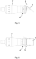
- the device for the spherical orientation of an optical element is illustrated in different perspectives and viewed from different angles.
- the device is adapted to be used to direct a light beam L, such as a laser beam.
- a light beam L such as a laser beam.
- the device can be operated so as to orient the optical element 1, such as a mirror, in the desired arrangement in space, which converges and directs the light beam L as a function of the position assumed by such an optical element 1.
- the device can also be used more generally to direct different optical elements and in different types of application scopes.
- the device comprises a support structure 2, an optical element 1 having an optically useful (non-numbered) surface adapted to interact with an incident light beam L (e.g., a laser beam).
- the device further comprises a mechanism 3 mounted on the support structure 2 and capable of arranging the optical element 1 by rotating it around a first and second fixed rotation axis X and Y perpendicular to each other.
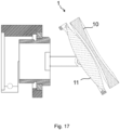
- the device can be mounted on a system for generating and/or focusing a laser 7 through fixing means of the support structure 2.
- fixing means may comprise for example one or more connecting plates 70 fixable by screws to the laser generating and/or focusing system and to the support structure 2.
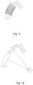
- the mechanism 3 comprises a first rotating assembly 4 around the first rotation axis X and a second rotating assembly 5 around the second rotation axis Y.
- the first assembly 4 comprises a tubular element 43 having a longitudinal axis coinciding with the first rotation axis X.
- the tubular element 43 defines a through cavity 44 adapted to be crossed by the light beam L and facing the optical element 1.
- the support structure 2 is provided with a support seat 20 of the tubular element 43, in which seat the tubular element 43 is rotatably coupled by a bearing 21, visible for example in the sectional view of figure 8 .
- the support structure 2 can be modified specifically for use with any laser generating and/or focusing system 7.
- the mechanism 3 comprises a first electromagnetic actuator 40 arranged to rotate the first assembly 4, i.e., to exert a thrust or pull stress along a first arcuate direction of actuation radially spaced from the first rotation axis X.
- the actuation mechanism is based on the interaction between a permanent magnet and the magnetic field induced by an electromagnetic coil. Since the current is supplied to the coil, a magnetic field is induced inside the electromagnetic coil. The permanent magnet located in this electromagnetic field is exposed to a magnetic force. This magnetic force drives the movement around the rotation axis.
- the first electromagnetic actuator 40 comprises a first fixed coil 41 and a first movable magnetic element 42, preferably consisting of a permanent magnet.
- the first magnetic element 42 is circumferentially arc-shaped and centred in the first rotation axis X, as shown in figure 11 or 12 and is coupled externally to the tubular element 43 so that it lies on said circumference centred in the first rotation axis X.
- the first magnetic element 42 is fixed externally to the sleeve surface of the tubular element 43 by a spacer element 45 extending from the tubular element 43 in a substantially radial direction with respect to the first rotation axis X.
- the first electromagnetic actuator 40 further comprises a first coil 41 fixed to the support structure 2 and shaped so as to have an arcuate housing seat 410 for rotating said first magnetic element 42.
- the curvature of the first magnetic element 42 is advantageously the same as that of the coil 41.
- the coil 41 consists of a metallic electromagnetic base on which the turns of a conductor are wound.
- the electromagnetic base consists of two curvilinear plate-shaped elements facing each other so as to form said arcuate seat 410.
- the second rotating assembly 5 comprises a support member 53 of the optical element 1, preferably consisting of a frame surrounding at least part of the outer perimeter thereof.
- the support member 53 is tiltingly fixed to the tubular element 43 around the second rotation axis Y by a pair of support arms 54 to form the second rotating assembly 5.
- the mechanism 3 comprises at least one second electromagnetic actuator 50 arranged to rotate the second rotating assembly 5 causing a thrust or pull stress on the latter along a second arcuate direction of actuation, transversely spaced with respect to the second rotation axis Y.
- the second electromagnetic actuator 50 is spaced from the coupling hinges of the support member 53 of the optical element with the support arms 54, placed on the second rotation axis Y.
- the second electromagnetic actuator 50 is placed respectively near the base of a support arm 54 constrained to the tubular element 43 and near a free end of the support member 53 of the optical element 1.
- the second electromagnetic actuator 5 comprises a second fixed coil 51 and a second movable magnetic element 52 circumferentially arc-shaped and centred in the second rotation axis Y.
- the second magnetic element 52 is coupled to the support member 53 of the optical element 1 such that it lies on said circumference centred in the second rotation axis Y.
- the second electromagnetic actuator 50 comprises a second coil 51 fixed to the support arm 54 and consequently to the first rotating assembly 4.
- the second coil 51 is configured so as to have an arcuate housing seat 510 for rotating said second magnetic element 52.
- the curvature of the second magnetic element 52 is advantageously the same as that of the arcuate seat 510.
- the curvature of the second magnetic element 52 is advantageously the same as that of the second coil 51.
- the second coil 51 also consists of a metallic electromagnetic base on which the turns of a conductor are wound.
- the electromagnetic base consists of two curvilinear plate-shaped elements facing each other so as to form said arcuate seat 510.
- optical elements 1 of the type intended to be crossed by the light beam also referred to as the see-through type.
- An example of such optical elements can be a polariser or a semi-transparent mirror, or - more generally - a beam splitter element.
- the device further comprises a system for generating and/or focusing a laser beam 7, of a type known per se, and adapted to emit the beam by directing it through the through cavity 44.
- the laser generating and/or focusing system 7 is fixed to the support structure 2 in an aligned position with respect to the through cavity 44 and, particularly, coaxial with the first rotation axis X.
- Both the first rotating assembly 4 and the second rotating assembly 5 comprise one or more rotary encoders 6 for feedback control.
- the encoders 6 are preferably integrated and can be of any type currently known, for example hall effect, optical, resistive or of another type and directly measure the output axis.
- the same principle is used for rotations around the first and the second rotation axis X and Y, and the actuators are positioned for different axes.
- the shape of the components is preferably the same for both actuators, but the dimensions are different, so that the first and the second actuator 40 and 50 are to scale.
- the minimum torque requirements for movement are in fact different for the rotation axes X and Y due to the mechanical design of the system.
- the first actuator 40 must compensate for the weights of the optical element 1, i.e., the beam deflection mirror, as well as the mirror support member 53, the mirror support arms 54, the second actuator of the axis Y and the encoder 6.
- the second electromagnetic actuator 50 must only compensate for the weight of the optical element 1 and the support member 53 of the optical element.
- a single electromagnetic actuator is positioned for each axis.
- multiple actuators can be provided for both the first rotating assembly 4 and the second rotating assembly 5.
- several first actuators 40 can be positioned circumferentially around the tubular element 43 and/or two second actuators on both support arms of the support member 53 of the optical element 1.
Landscapes
- Physics & Mathematics (AREA)
- General Physics & Mathematics (AREA)
- Optics & Photonics (AREA)
- Mechanical Light Control Or Optical Switches (AREA)
- Lenses (AREA)
- Mechanical Optical Scanning Systems (AREA)
Claims (4)
- Vorrichtung für die sphärische Ausrichtung eines optischen Elements (1), wobei die Vorrichtung eine Trägerstruktur (2) umfasst, ein optisches Element (1) eine optisch nutzbare Oberfläche aufweist, die zum Interagieren mit einem einfallenden Lichtstrahl (L) angepasst ist, ein Mechanismus (3) an der Trägerstruktur (2) montiert und in der Lage ist, das optische Element (1) in Raum um eine erste und eine zweite Drehachse (X, Y) senkrecht zueinander zu drehen, wobei der Mechanismus (3) eine erste Drehanordnung (4) um die erste Drehachse (X) und eine zweite Drehanordnung (5) um die zweite Drehachse (Y) umfasst, wobei die erste Drehanordnung (4) einen um die erste Drehachse (X) definierten durchgehenden Hohlraum (44) aufweist, wobei der durchgehende Hohlraum (44) angepasst ist, um von dem Lichtstrahl (L) durchquert zu werden, und dem optischen
Element (1) zugewandt ist,wobei der Mechanismus (3) mindestens einen ersten elektromagnetischen Aktor (40), der zum Drehen der ersten Drehanordnung (4) angeordnet ist, und mindestens einen zweiten elektromagnetischen Aktor (50) umfasst, der zum Drehen der zweiten Drehanordnung (5) angeordnet istdadurch gekennzeichnet, dassdie erste Drehanordnung (4) drehbar an die Trägerstruktur (2) gekoppelt ist und die zweite Drehanordnung (5) an die erste Drehanordnung (4) gekoppelt ist und ein Trägerelement (53) des optischen Elements (1) umfasst,wobei der erste elektromagnetische Aktor (40) eine erste feststehende Spule (41) und ein erstes bewegliches Magnetelement (42) umfasst und der zweite elektromagnetische Aktor (5) eine zweite feststehende Spule (51) und ein zweites bewegliches Magnetelement (52) umfasst,wobei die erste Drehanordnung (4) ein rohrförmiges Element (43) mit einer Längsachse umfasst, die mit der ersten Drehachse (X) zusammenfällt und
den durchgehenden Hohlraum (44) definiert, das erste bewegliche Magnetelement (42) in Umfangsrichtung bogenförmig und in der ersten Drehachse (X) zentriert ist, das erste bewegliche Magnetelement (42) extern mit dem rohrförmigen Element (43) gekoppelt ist, sodass das erste bewegliche Magnetelement (42) auf dem in der ersten Drehachse (X) zentrierten Umfang liegt, der erste elektromagnetische Aktor (40) ferner eine erste Spule (41) umfasst, die an der Trägerstruktur (2) befestigt und so geformt ist, dass sie einen bogenförmigen Gehäusesitz (410) zum Drehen des ersten beweglichen Magnetelements (42) aufweist. - Vorrichtung nach Anspruch 1, wobei die Trägerstruktur (2) mit einem rohrförmigen Elementstützsitz (20) bereitgestellt ist, wobei das rohrförmige Element (43) in dem Sitz drehbar mittels eines Lagers (21) gekoppelt ist.
- Vorrichtung nach Anspruch 1, wobei der zweite elektromagnetische Aktor (50) ein zweites Magnetelement (52) umfasst, das in Umfangsrichtung bogenförmig und in der zweiten Drehachse (Y) zentriert ist, wobei das zweite Magnetelement (52) mit dem Trägerelement (51) des optischen Elements (1) gekoppelt ist, sodass das zweite Magnetelement (52) auf dem in der zweiten Drehachse (Y) zentrierten Umfang liegt, der zweite elektromagnetische Aktor (50) ferner eine zweite Spule (51) umfasst, die an der ersten Drehanordnung (4) befestigt und so geformt ist, dass sie einen bogenförmigen Gehäusesitz (510) zum Drehen des zweiten Magnetelements (52) aufweist.
- Vorrichtung nach einem oder mehreren der vorstehenden Ansprüche, wobei die erste Drehanordnung (4) und/oder die zweite Drehanordnung (5) einen oder mehrere Drehgeber (6) zum Rückkupplungssteuern umfassen.
Applications Claiming Priority (2)
| Application Number | Priority Date | Filing Date | Title |
|---|---|---|---|
| IT102020000002155A IT202000002155A1 (it) | 2020-02-04 | 2020-02-04 | Dispositivo per l’orientamento sferico di un elemento ottico, in particolare per dirigere un fascio di luce, quale un fascio laser |
| PCT/IB2021/050897 WO2021156779A1 (en) | 2020-02-04 | 2021-02-04 | Device for the spherical orientation of an optical element, in particular for directing a light beam, such as a laser beam |
Publications (3)
| Publication Number | Publication Date |
|---|---|
| EP4100779A1 EP4100779A1 (de) | 2022-12-14 |
| EP4100779C0 EP4100779C0 (de) | 2025-04-09 |
| EP4100779B1 true EP4100779B1 (de) | 2025-04-09 |
Family
ID=70480520
Family Applications (1)
| Application Number | Title | Priority Date | Filing Date |
|---|---|---|---|
| EP21707781.7A Active EP4100779B1 (de) | 2020-02-04 | 2021-02-04 | Vorrichtung zur sphärischen ausrichtung eines optischen elements, insbesondere zur führung eines lichtstrahls, wie etwa eines laserstrahls |
Country Status (4)
| Country | Link |
|---|---|
| US (1) | US12461359B2 (de) |
| EP (1) | EP4100779B1 (de) |
| IT (1) | IT202000002155A1 (de) |
| WO (1) | WO2021156779A1 (de) |
Citations (1)
| Publication number | Priority date | Publication date | Assignee | Title |
|---|---|---|---|---|
| JP2007222203A (ja) * | 2006-02-21 | 2007-09-06 | Sumida Corporation | ミラー駆動機構およびこのミラー駆動機構を具備する撮像装置 |
Family Cites Families (9)
| Publication number | Priority date | Publication date | Assignee | Title |
|---|---|---|---|---|
| US5966991A (en) | 1997-04-23 | 1999-10-19 | Universite Laval | Two degree-of-freedom spherical orienting device |
| JP4807695B2 (ja) * | 2000-07-24 | 2011-11-02 | 日本発條株式会社 | 探査光走査用アクチュエータ |
| CN1251125C (zh) * | 2001-03-26 | 2006-04-12 | 索尼公司 | 条形码读取装置以及条形码读取装置用可动反射镜以及其制造方法 |
| US6856437B2 (en) * | 2002-02-01 | 2005-02-15 | Terabeam Corporation | Fast steering mirror |
| US7465107B2 (en) * | 2004-09-21 | 2008-12-16 | Canon Kabushiki Kaisha | Photographing apparatus and control method therefor |
| JP2008249375A (ja) * | 2007-03-29 | 2008-10-16 | Topcon Corp | 3次元位置測定装置 |
| US20080304023A1 (en) * | 2007-06-06 | 2008-12-11 | Hyun Cheal Bang | Tilting actuator for light-projection |
| JP6069628B2 (ja) * | 2012-12-03 | 2017-02-01 | 北陽電機株式会社 | 偏向装置、光走査装置及び走査式測距装置 |
| EP3149527B1 (de) | 2014-05-30 | 2023-08-02 | Fondazione Istituto Italiano di Tecnologia | Vorrichtung zur sphärischen ausrichtung eines optischen elements, insbesondere zur führung eines lichtstrahls, wie etwa eines laserstrahls |
-
2020
- 2020-02-04 IT IT102020000002155A patent/IT202000002155A1/it unknown
-
2021
- 2021-02-04 WO PCT/IB2021/050897 patent/WO2021156779A1/en not_active Ceased
- 2021-02-04 EP EP21707781.7A patent/EP4100779B1/de active Active
- 2021-02-04 US US17/797,157 patent/US12461359B2/en active Active
Patent Citations (1)
| Publication number | Priority date | Publication date | Assignee | Title |
|---|---|---|---|---|
| JP2007222203A (ja) * | 2006-02-21 | 2007-09-06 | Sumida Corporation | ミラー駆動機構およびこのミラー駆動機構を具備する撮像装置 |
Also Published As
| Publication number | Publication date |
|---|---|
| EP4100779A1 (de) | 2022-12-14 |
| EP4100779C0 (de) | 2025-04-09 |
| US12461359B2 (en) | 2025-11-04 |
| IT202000002155A1 (it) | 2021-08-04 |
| WO2021156779A1 (en) | 2021-08-12 |
| US20230050641A1 (en) | 2023-02-16 |
Similar Documents
| Publication | Publication Date | Title |
|---|---|---|
| CN102483519B (zh) | 单镜光学扫描仪 | |
| CA2305320C (en) | Robotic manipulator | |
| KR100872031B1 (ko) | 자기구동기를 이용한 비접촉식 스캐너 | |
| EP3006975A2 (de) | Vorrichtung zum Kippen eines optischen Elements, insbesondere eines Spiegels | |
| EP3525025B1 (de) | Auswuchtvorrichtung für drehvorrichtung | |
| EP2078212A1 (de) | Scanning-system für lidar | |
| AU2005263777B2 (en) | Geodesic measuring instrument with a piezo drive | |
| WO2003025657A1 (en) | Actuator-controlled mirror with z-stop mechanism | |
| JP6266692B2 (ja) | 光学スキャン機構 | |
| US10738973B2 (en) | Device for the spherical orientation of an optical element, in particular for directing a light beam, such as a laser beam | |
| CN115427679A (zh) | 致动器组件 | |
| EP1774380B1 (de) | Optischer schalter | |
| JPH05128561A (ja) | 光デイスク装置のトラツキングアクチユエータ | |
| EP4100779B1 (de) | Vorrichtung zur sphärischen ausrichtung eines optischen elements, insbesondere zur führung eines lichtstrahls, wie etwa eines laserstrahls | |
| JP2014048668A (ja) | 各々が2個の死点で層状に重なり合う2個の機械的動作伝達アセンブリーを含む角度位置決め装置 | |
| JP3189856B2 (ja) | 可動ミラー支持装置 | |
| CN117715599A (zh) | 外科器械及其转向传动机构 | |
| US6693401B1 (en) | Precision positioning tilt device | |
| CN110187485B (zh) | 具有可移动光束偏转器的手术显微镜、其操作方法和改造套件 | |
| JP3204793B2 (ja) | 内視鏡装置 | |
| JP2020173021A (ja) | アクチュエータシステム、光学系、および、光学系中に光学素子を位置決めする方法 | |
| WO2007145236A1 (ja) | アクチュエータ | |
| WO2011089429A1 (en) | Actuation devices | |
| JPH06313853A (ja) | 観察装置 | |
| RU2369887C1 (ru) | Лазерное сканирующее устройство |
Legal Events
| Date | Code | Title | Description |
|---|---|---|---|
| STAA | Information on the status of an ep patent application or granted ep patent |
Free format text: STATUS: UNKNOWN |
|
| STAA | Information on the status of an ep patent application or granted ep patent |
Free format text: STATUS: THE INTERNATIONAL PUBLICATION HAS BEEN MADE |
|
| PUAI | Public reference made under article 153(3) epc to a published international application that has entered the european phase |
Free format text: ORIGINAL CODE: 0009012 |
|
| STAA | Information on the status of an ep patent application or granted ep patent |
Free format text: STATUS: REQUEST FOR EXAMINATION WAS MADE |
|
| 17P | Request for examination filed |
Effective date: 20220902 |
|
| AK | Designated contracting states |
Kind code of ref document: A1 Designated state(s): AL AT BE BG CH CY CZ DE DK EE ES FI FR GB GR HR HU IE IS IT LI LT LU LV MC MK MT NL NO PL PT RO RS SE SI SK SM TR |
|
| DAV | Request for validation of the european patent (deleted) | ||
| DAX | Request for extension of the european patent (deleted) | ||
| GRAP | Despatch of communication of intention to grant a patent |
Free format text: ORIGINAL CODE: EPIDOSNIGR1 |
|
| STAA | Information on the status of an ep patent application or granted ep patent |
Free format text: STATUS: GRANT OF PATENT IS INTENDED |
|
| INTG | Intention to grant announced |
Effective date: 20240926 |
|
| GRAS | Grant fee paid |
Free format text: ORIGINAL CODE: EPIDOSNIGR3 |
|
| GRAA | (expected) grant |
Free format text: ORIGINAL CODE: 0009210 |
|
| STAA | Information on the status of an ep patent application or granted ep patent |
Free format text: STATUS: THE PATENT HAS BEEN GRANTED |
|
| AK | Designated contracting states |
Kind code of ref document: B1 Designated state(s): AL AT BE BG CH CY CZ DE DK EE ES FI FR GB GR HR HU IE IS IT LI LT LU LV MC MK MT NL NO PL PT RO RS SE SI SK SM TR |
|
| REG | Reference to a national code |
Ref country code: GB Ref legal event code: FG4D |
|
| REG | Reference to a national code |
Ref country code: CH Ref legal event code: EP |
|
| REG | Reference to a national code |
Ref country code: DE Ref legal event code: R096 Ref document number: 602021028866 Country of ref document: DE |
|
| REG | Reference to a national code |
Ref country code: IE Ref legal event code: FG4D |
|
| U01 | Request for unitary effect filed |
Effective date: 20250422 |
|
| U07 | Unitary effect registered |
Designated state(s): AT BE BG DE DK EE FI FR IT LT LU LV MT NL PT RO SE SI Effective date: 20250425 |
|
| PG25 | Lapsed in a contracting state [announced via postgrant information from national office to epo] |
Ref country code: ES Free format text: LAPSE BECAUSE OF FAILURE TO SUBMIT A TRANSLATION OF THE DESCRIPTION OR TO PAY THE FEE WITHIN THE PRESCRIBED TIME-LIMIT Effective date: 20250409 |
|
| PG25 | Lapsed in a contracting state [announced via postgrant information from national office to epo] |
Ref country code: NO Free format text: LAPSE BECAUSE OF FAILURE TO SUBMIT A TRANSLATION OF THE DESCRIPTION OR TO PAY THE FEE WITHIN THE PRESCRIBED TIME-LIMIT Effective date: 20250709 Ref country code: GR Free format text: LAPSE BECAUSE OF FAILURE TO SUBMIT A TRANSLATION OF THE DESCRIPTION OR TO PAY THE FEE WITHIN THE PRESCRIBED TIME-LIMIT Effective date: 20250710 |
|
| PG25 | Lapsed in a contracting state [announced via postgrant information from national office to epo] |
Ref country code: PL Free format text: LAPSE BECAUSE OF FAILURE TO SUBMIT A TRANSLATION OF THE DESCRIPTION OR TO PAY THE FEE WITHIN THE PRESCRIBED TIME-LIMIT Effective date: 20250409 |
|
| PG25 | Lapsed in a contracting state [announced via postgrant information from national office to epo] |
Ref country code: HR Free format text: LAPSE BECAUSE OF FAILURE TO SUBMIT A TRANSLATION OF THE DESCRIPTION OR TO PAY THE FEE WITHIN THE PRESCRIBED TIME-LIMIT Effective date: 20250409 |
|
| PG25 | Lapsed in a contracting state [announced via postgrant information from national office to epo] |
Ref country code: RS Free format text: LAPSE BECAUSE OF FAILURE TO SUBMIT A TRANSLATION OF THE DESCRIPTION OR TO PAY THE FEE WITHIN THE PRESCRIBED TIME-LIMIT Effective date: 20250709 |
|
| PG25 | Lapsed in a contracting state [announced via postgrant information from national office to epo] |
Ref country code: IS Free format text: LAPSE BECAUSE OF FAILURE TO SUBMIT A TRANSLATION OF THE DESCRIPTION OR TO PAY THE FEE WITHIN THE PRESCRIBED TIME-LIMIT Effective date: 20250809 |
|
| PG25 | Lapsed in a contracting state [announced via postgrant information from national office to epo] |
Ref country code: SM Free format text: LAPSE BECAUSE OF FAILURE TO SUBMIT A TRANSLATION OF THE DESCRIPTION OR TO PAY THE FEE WITHIN THE PRESCRIBED TIME-LIMIT Effective date: 20250409 |
|
| PG25 | Lapsed in a contracting state [announced via postgrant information from national office to epo] |
Ref country code: CZ Free format text: LAPSE BECAUSE OF FAILURE TO SUBMIT A TRANSLATION OF THE DESCRIPTION OR TO PAY THE FEE WITHIN THE PRESCRIBED TIME-LIMIT Effective date: 20250409 |
|
| PG25 | Lapsed in a contracting state [announced via postgrant information from national office to epo] |
Ref country code: SK Free format text: LAPSE BECAUSE OF FAILURE TO SUBMIT A TRANSLATION OF THE DESCRIPTION OR TO PAY THE FEE WITHIN THE PRESCRIBED TIME-LIMIT Effective date: 20250409 |
|
| PLBE | No opposition filed within time limit |
Free format text: ORIGINAL CODE: 0009261 |
|
| STAA | Information on the status of an ep patent application or granted ep patent |
Free format text: STATUS: NO OPPOSITION FILED WITHIN TIME LIMIT |
|
| REG | Reference to a national code |
Ref country code: CH Ref legal event code: L10 Free format text: ST27 STATUS EVENT CODE: U-0-0-L10-L00 (AS PROVIDED BY THE NATIONAL OFFICE) Effective date: 20260218 |
|
| 26N | No opposition filed |
Effective date: 20260112 |
|
| U20 | Renewal fee for the european patent with unitary effect paid |
Year of fee payment: 6 Effective date: 20260227 |
|
| PGFP | Annual fee paid to national office [announced via postgrant information from national office to epo] |
Ref country code: GB Payment date: 20260227 Year of fee payment: 6 |