EP4100673B1 - Unité fonctionnelle mécanique à fonctionnement passif pour soupape de protection contre les ondes de choc, et soupape de protection contre les ondes de choc associée - Google Patents
Unité fonctionnelle mécanique à fonctionnement passif pour soupape de protection contre les ondes de choc, et soupape de protection contre les ondes de choc associée Download PDFInfo
- Publication number
- EP4100673B1 EP4100673B1 EP21703195.4A EP21703195A EP4100673B1 EP 4100673 B1 EP4100673 B1 EP 4100673B1 EP 21703195 A EP21703195 A EP 21703195A EP 4100673 B1 EP4100673 B1 EP 4100673B1
- Authority
- EP
- European Patent Office
- Prior art keywords
- flow
- shock wave
- valve flap
- valve
- functional unit
- Prior art date
- Legal status (The legal status is an assumption and is not a legal conclusion. Google has not performed a legal analysis and makes no representation as to the accuracy of the status listed.)
- Active
Links
Images


Classifications
-
- F—MECHANICAL ENGINEERING; LIGHTING; HEATING; WEAPONS; BLASTING
- F16—ENGINEERING ELEMENTS AND UNITS; GENERAL MEASURES FOR PRODUCING AND MAINTAINING EFFECTIVE FUNCTIONING OF MACHINES OR INSTALLATIONS; THERMAL INSULATION IN GENERAL
- F16K—VALVES; TAPS; COCKS; ACTUATING-FLOATS; DEVICES FOR VENTING OR AERATING
- F16K17/00—Safety valves; Equalising valves, e.g. pressure relief valves
- F16K17/006—Safety valves; Equalising valves, e.g. pressure relief valves specially adapted for shelters
-
- A—HUMAN NECESSITIES
- A62—LIFE-SAVING; FIRE-FIGHTING
- A62B—DEVICES, APPARATUS OR METHODS FOR LIFE-SAVING
- A62B13/00—Special devices for ventilating gasproof shelters
-
- A—HUMAN NECESSITIES
- A62—LIFE-SAVING; FIRE-FIGHTING
- A62C—FIRE-FIGHTING
- A62C4/00—Flame traps allowing passage of gas but not of flame or explosion wave
-
- F—MECHANICAL ENGINEERING; LIGHTING; HEATING; WEAPONS; BLASTING
- F16—ENGINEERING ELEMENTS AND UNITS; GENERAL MEASURES FOR PRODUCING AND MAINTAINING EFFECTIVE FUNCTIONING OF MACHINES OR INSTALLATIONS; THERMAL INSULATION IN GENERAL
- F16K—VALVES; TAPS; COCKS; ACTUATING-FLOATS; DEVICES FOR VENTING OR AERATING
- F16K17/00—Safety valves; Equalising valves, e.g. pressure relief valves
- F16K17/20—Excess-flow valves
- F16K17/22—Excess-flow valves actuated by the difference of pressure between two places in the flow line
- F16K17/24—Excess-flow valves actuated by the difference of pressure between two places in the flow line acting directly on the cutting-off member
- F16K17/28—Excess-flow valves actuated by the difference of pressure between two places in the flow line acting directly on the cutting-off member operating in one direction only
Definitions
- the invention relates to a passively operating mechanical functional unit for a shock wave protection valve, in particular for a ventilation system, a flow channel with a flow area through which a ventilation stream can flow in a flow direction and which can be blocked in a blocking direction in the event of a fault as a result of a shock wave propagating in the blocking direction .
- the functional unit further comprises a leaf-like valve flap which is held in an open position and which, in the event of a fault, can be deflected by the shock wave at least in sections transversely to the flow direction into the flow area into a closed position, in which the flow area is blocked in the blocking direction by the valve flap.
- the invention also relates to a shock wave protection valve comprising such a functional unit as well as a ventilation system and a testing system with such a shock valve.
- the invention further relates to a method for measuring a closing pressure and/or a flow resistance of such a shock wave protection valve and its use in a testing laboratory.
- shock wave protection valves are primarily used in areas where ventilation is required, but there is a risk that people or systems could be damaged as a result of compressed air surges.
- shock wave protection valves are used as pressure wave protection for the supply and exhaust air openings of ventilation ducts of shelters for people or systems, containments for nuclear power plants, offshore systems or military buildings.
- Shock wave protection valves offer effective protection against the effects of pressure waves from, for example, nuclear or conventional detonations and prevent them Propagation of the pressure wave into the ventilation ducts of the ventilation system or out of the ventilation ducts.
- Active shock wave protection valves require external energy and a control system for pressure-safe closure. With the help of sensors, they register the increase in pressure caused by the incoming shock wave and then use an actuator to trigger the closure of the valve.
- Passive shock wave protection valves function without external energy or control, react only to the effect of the shock wave and, due to their structural nature, prevent pressure from spreading within the pipelines and into adjacent parts of the system.
- Such a passive shock wave protection valve in a supply air or exhaust air duct of a boiler in the military sector is, for example, from US 3,139,108 known.
- This has several elastic valve plates, which are arranged between adjacent passage openings for an air flow. In the open position, the valve plates protrude obliquely outwards with respect to a flow direction into the incoming or outgoing air flow.
- the valve flaps are bent into a closed position on the passage openings, so that they are closed. After the shock wave has passed through, the elastic valve plates automatically return to the open position.
- valve plates have to protrude into the air flow with a considerable inclination so that there is sufficient surface area for the shock wave to attack.
- this is accompanied by considerable flow resistance.
- valve plates have to be bent relatively strongly out of the open position in order to close them, which creates the risk of undesirable plastic deformation and requires special, cost-intensive materials for the valve plates.
- the application relates to the military sector and is therefore not easily and economically applicable in a civil sector, for example.
- DE202016004209U1 discloses a passively operating mechanical functional unit according to the preamble of claim 1.
- the object of the invention is therefore to create a passively operating mechanical functional unit for a shock wave protection valve and a shock wave protection valve belonging to the technical field mentioned at the beginning, which Overcome disadvantages of the prior art.
- a further object of the invention is to provide a method for measuring a closing pressure and/or a flow resistance and a use of such a shock wave protection valve.
- a passively operating mechanical functional unit for a shock wave protection valve in particular for a ventilation system, comprises a flow channel with a flow area through which a ventilation flow can flow in a flow direction and which can be blocked in a blocking direction in the event of a fault as a result of a shock wave propagating in the blocking direction is.
- the functional unit further comprises a leaf-like valve flap which is held in an open position and which, in the event of a fault, can be deflected by the shock wave at least in sections transversely to the flow direction into the flow area into a closed position, in which the flow area is blocked by the valve flap in the blocking direction.
- the functional unit is characterized in that the valve flap is essentially aligned in the flow direction in the open position and is arranged between a storage space arranged in the flow channel and open against the blocking direction and the flow area in such a way that in the event of a malfunction when the shock wave passes through the shock wave in the storage space a pressure can be built up, which presses the valve flap at least in sections transversely to the direction of flow and deflects it into the flow area, so that the valve flap reaches the closed position.
- One dimension in the direction of flow is referred to here as “length”, while two dimensions aligned perpendicular to the direction of flow and perpendicular to each other are referred to as “width” and “height”.
- the height refers to the dimension in the direction in which the valve flap is arranged between the storage space and the flow area.
- the “flow channel” refers to a section of the functional unit that extends in the direction of flow and extends essentially over its length in the longitudinal direction on both sides Has openings extending across the entire end cross section.
- the cross section of the flow channel can be constant or change in the direction of flow.
- the cross section can fundamentally be round or polygonal, in particular rectangular.
- the ventilation flow can flow through the openings over its entire end cross section.
- the flow channel is enclosed by one or more boundary walls and is delimited by them perpendicular to the direction of flow.
- the “flow area” refers to an area of the flow channel through which the ventilation flow can flow largely unhindered in the direction of flow if there is no malfunction.
- the flow area forms a partial area of the flow channel and has an effective cross section which is continuous in the flow direction over the entire length of the flow channel for the ventilation flow if there is no malfunction.
- a malfunction occurs when, for example, as a result of a detonation or deflagration, a pressure or shock wave occurs in the ventilation flow, which the functional unit is designed and designed to block. If there is no malfunction during operation, this is referred to as normal operation.
- valve flap-like refers to a design of the valve flap as a plate with two main surfaces, which are delimited by circumferential, relatively thin edges.
- the valve flap can be made, for example, from a sheet metal such as a stainless steel sheet.
- the valve flap can be deflected at least in sections transversely to the flow direction into the flow area.
- the valve flap can, for example, be designed to be rigid and pivotable about a pivot axis, or it can be designed to be flexible and deflected at least in sections into the flow area by bending.
- the “open position” refers to a position of the valve flap in which it is arranged in the normal state, in particular in normal operation.
- the valve flap In the open position, the valve flap is essentially aligned in the flow direction, ie the main surfaces of the valve flap are arranged essentially parallel to the flow direction.
- essentially parallel can include minor deviations from a parallel position, which can amount to up to 15°.
- the effective cross section of the flow area is therefore not or only slightly reduced or blocked by the valve flap when it is in the open position.
- the “closed position” refers to a position of the valve flap in which the flow area of the valve flap is essentially completely closed, so that the ventilation flow can no longer flow through it, at least in the blocking direction. It goes without saying that there is no need for a hermetic seal in the closed position. It is important that in the closed position the flow area is blocked for the passage of a sufficiently strong pressure wave in the ventilation flow, in particular a shock wave.
- blocking direction refers to the direction in which the functional unit can block the passage of a shock wave.
- the blocking direction can be directed in the same direction or in the opposite direction to the flow direction, depending on whether the functional unit is intended for use in the sense of a pressure valve or in the sense of a check valve.
- the storage space is designed in the flow channel next to the valve flap in such a way that the valve flap is arranged between the flow area and the storage space.
- the storage space defines a storage volume in the flow channel and covers a portion of the cross section of the flow channel through which the ventilation flow flows.
- the storage space is at least partially open, so that the storage volume defined by the storage space communicates with the ventilation flow.
- the storage space is essentially closed off from the rest of the flow channel, in particular from the flow area, and thus forms a non-flowable storage area in the flow channel.
- the storage space can be closed off, for example, by boundary walls, in particular, for example, a housing of a shock wave protection valve or separate partition walls provided for this purpose.
- a dynamic pressure is built up in the storage space, in contrast to the continuous flow area. This creates a pressure difference between the storage space and the flow area, ie an overpressure in the storage space, which acts on the valve flap arranged between them.
- the valve flap is designed to be deflectable in such a way that the excess pressure must exceed a certain threshold value so that the valve flap is deflected from the open position into the closed position.
- the Threshold value for the overpressure defines a transition from normal operation to a fault.
- the valve flap By arranging the valve flap between the storage space and the flow area according to the invention, the excess pressure built up in the storage space can act directly and over a large area on the valve flap. With a comparatively small flow cross-section of the storage space, a comparatively large force can be exerted on the valve flap. In this way it is achieved that, with low flow resistance, the valve flap is reliably deflected into the flow area in the event of a malfunction and reaches the closed position.
- the pressure of the shock wave arriving in the blocking direction is converted by the storage space into a force transverse to the flow direction on the valve flap.
- the valve flap does not need to have an attack surface directed towards the incoming shock wave in the open position for deflection, i.e. no angle of attack with respect to the direction of flow is required.
- the valve flap can be arranged aligned in the flow direction in the open position. This means that the valve flap does not protrude into the flow area in the open position and does not impair the effective cross section of the flow area in favor of low flow resistance.
- the valve flap is held in the open position, i.e. is fastened in such a way that in the absence of external forces, the valve flap remains in the open position, which means that no flow energy is or has to be taken from the ventilation flow as it flows through to keep it open.
- a structurally simple functional unit for a shock wave protection valve, which has a reliable blocking property and a comparatively low flow resistance.
- the functional unit according to the invention is preferably used for room ventilation.
- the functional unit is particularly suitable for low-pressure applications in which a ventilation flow in normal operation has a pressure, for example, of the order of around 200 Pa and in the event of a fault, a pressure, for example, in the range of around 300 Pa.
- the invention is particularly suitable for applications in which the pressure loss in the valve is a maximum of 600 Pa during normal operation.
- the valve flap can be deflected resiliently into the closed position.
- the valve flap is preferably resiliently deflectable in such a way that a restoring force is exerted on the valve flap, which returns it from a deflected position, in particular the closed position, to the open position.
- the resiliently deflectable valve flap can be achieved by making the valve flap resiliently flexible, for example at least in some areas or as a whole.
- the valve flap can be designed to be rigid and can be deflected via a spring-loaded hinge or joint. Of course, combinations of spring-loaded joints and spring-elastic valve flaps are also conceivable.
- valve flap can be designed to be plastically deformable at least in some areas, so that the valve flap is permanently deformed in the course of deflection and remains in the closed position after a fault.
- functional units require maintenance work or replacement of the valve flap after a malfunction.
- the valve flap is preferably fastened in the flow channel with a foot area directed in the blocking direction and extends from the foot area counter to the blocking direction.
- the valve flap has a certain angle of attack with respect to the flow direction, at least partially, and can therefore be detected by an inflow associated with the incoming shock wave. Due to the associated redirection of a portion of the flow at the valve flap, an additional force is generated on the valve flap, which supports or accelerates the transition to the closed position.
- the foot area of the valve flap is firmly fastened in the flow channel and the valve flap is designed to be flexible at least in some areas.
- the deflection of the valve flap is achieved through its flexibility. This has the advantage that the deflection of the valve flap does not require any moving parts that require maintenance and can lose functionality over time, for example due to contamination or corrosion.
- the valve flap is designed to be resiliently flexible, so that it is automatically returned to the open position after a malfunction.
- valve flap articulated in the foot area
- the foot area of the valve flap can be attached in an articulated manner in the flow channel.
- the entire valve flap can be deflected around the joint.
- attachment via a joint does not exclude the fact that the valve flap can also be flexible, in particular resiliently flexible.
- the valve flap is preferably attached in a resiliently articulated manner, i.e. the joint is spring-loaded in order to automatically return the valve flap to the open position after a malfunction.
- the valve flap preferably has a closing edge at a free end pointing counter to the blocking direction, with which it rests against a boundary wall of the flow area in the closed position.
- the boundary wall against which the valve flap rests in the closed position is generally opposite the valve flap in terms of the flow area when it is in the open position.
- the closing element forms a defined contact surface of the valve flap for contact with the boundary wall.
- the closing edge can, for example, be formed by an angled area at the free end of the valve flap, with which the valve flap lies flat against the boundary wall in the inclined closed position for better sealing. The angled area can also help stiffen the free end of the valve flap.
- a seat can also be formed on the boundary wall, in which the closing edge is arranged for better sealing in the closed position.
- the valve flap is resiliently biased towards the storage space in the open position, with at least one stop element being formed, in particular in the storage space, against which the valve flap rests in the open position. In the open position, the valve flap is thus pressed against the stop element by the resilient preload.
- the stop element is designed such that the valve flap is aligned in the direction of flow when it rests against it in the open position. The stop element prevents the valve flap from being deflected from the open position into the storage space.
- the stop element can comprise a stop rib aligned in the direction of flow with a stop edge against which the valve flap rests. Pin-like or block-like elements are also conceivable, which prevent the valve flap from being deflected into the storage space.
- the stop element can, for example, be attached to a boundary wall or to a support to which the valve flap is attached (see below).
- the resilient preload causes a spring force to act on the valve flap towards the storage space.
- the functional unit can include an additional spring element or, if present, the same spring element can apply the spring load towards the storage space, which enables the valve flap to be deflected resiliently into the flow area.
- this itself can be designed in such a way that a spring force acts towards the storage space in the open position.
- the valve flap can, for example, be designed to be angled towards the storage space in such a way that in the relaxed state, that is to say if the stop element were not present, it is at least partially deflected into the storage space.
- the valve flap can be angled towards the storage space at the foot area.
- valve flap in this particular embodiment is resiliently biased towards the storage space and rests against the stop element in the open position, the valve flap is not completely free and it can be prevented that the valve flap During normal operation, the ventilation flow causes undesirable oscillations or deflects it into the storage space.
- the spring load can be adapted to the specific conditions of the air flow.
- the mechanical functional unit therefore preferably comprises at least two support ribs aligned in the flow direction and arranged in the flow area, each of which has at least one support edge for the valve flap and against which the valve flap can rest in the closed position.
- the support edges are preferably arranged next to one another at a distance from one another in the width direction and are designed in such a way that they support the valve flap in the closed position against the blocking direction. In the closed position, the valve flap preferably rests with one of its main surfaces on the support edges.
- the support ribs preferably have a constant distance in the width direction. More preferably, the support ribs are connected to one another in pairs via a fastening bridge, in particular U-shaped in cross section, whereby two support ribs can be mounted in the flow channel via the one fastening bridge.
- the supporting ribs connected in pairs increase the structural stability of the supporting ribs. Adjacent pairs of supporting ribs connected in pairs can be screwed together on the adjacent supporting ribs, for example with a stabilizing intermediate layer, in order to further increase the structural stability.
- the pairs of supporting ribs connected via the fastening bridge can be made, for example, as a stamped and bent part from a sheet of metal, in particular a stainless steel sheet.
- valve flap in the closed position the valve flap is advantageously inclined in the blocking direction relative to the flow direction in order to be able to absorb the forces acting due to an incoming shock wave particularly well in the event of a malfunction.
- the support edges of the support ribs are therefore also advantageously inclined in the blocking direction relative to the flow direction. In this way, the support edges can optimally support the valve flap deflected into the flow area in the inclined closed position.
- the angle of inclination of the support edges is preferably less than 45°, preferably less than 30°, which supports the valve flap in a particularly resistant orientation in the closed position.
- the support edges preferably extend up to a boundary wall of the flow area, which is opposite the valve flap with respect to the flow area when the valve flap is in the open position.
- the support edges are curved with a constantly increasing angle of inclination relative to the direction of flow.
- a flexible valve flap can thus rest against the support edges during the transition to the closed position from the foot area to the free end with an increasing inclination upstream. Due to the curvature, an even contact can be achieved without the flexible valve flap buckling.
- spring-elastic valve flaps it can be prevented that in the event of a fault an elasticity range is exceeded and the valve flap is plastically deformed.
- the valve flap has a length in the flow direction which is at least twice as large as a height of the flow area.
- the height of the flow area refers to the greatest vertical distance between the valve flap in the open position and an opposite boundary wall of the flow area.
- the valve flap forms a boundary wall of the storage space, especially in the open position.
- the valve flap preferably forms a boundary wall of the storage space facing the flow area and preferably at the same time a boundary wall of the flow area facing the storage space.
- the further boundary walls of the storage space can be formed, for example, by boundary walls of the flow channel or by separate wall elements and are preferably designed to be rigid and unchangeable.
- the valve flap forms a variable boundary wall of the storage space, the storage volume of which changes during the deflection of the valve flap, i.e. during the transition from the open position to the closed position.
- the storage space In order to develop the greatest possible force on the valve flap, the storage space, according to a preferred embodiment, extends transversely to the flow direction essentially over the entire width of the valve flap. In this way, the force resulting from the excess pressure that can build up in the storage space can act across the entire width of the valve flap. For the same reasons, it is also advantageous if the storage space extends essentially over the entire length of the valve flap in the direction of flow. In this way, the force acting on the valve flap can be maximized.
- the storage space can in principle also be designed to be less wide or less long than the valve flap, for example if that is to be expected in the event of a malfunction Increase in pressure would lead to excessive force if it were to act on the entire main surface of the valve flap.
- valve flap extends transversely to the flow direction essentially over an entire width of the flow area. In this way it can be ensured that the flow area can be completely closed by the valve flap.
- the valve flap and in particular the flow area preferably extend over the entire width of the flow channel. In this way, the flow channel can be optimally utilized, which ultimately enables a compact size of the functional unit.
- the storage space has a lower height than the flow area. In this way, for a given cross section of the flow channel, the effective cross section of the flow area can be relatively large, while the storage space only takes up a small proportion of the inlet cross section of the flow channel.
- the flow direction is aligned with the blocking direction in an intended operation.
- the passage of a pressure or shock wave in the direction of the flowing air stream can be blocked, so that the functional unit is suitable for use as a pressure valve.
- the flow direction is opposite to the blocking direction in an intended operation.
- the passage of a pressure or shock wave can be blocked against the direction of the flowing air stream, so that the functional unit is suitable for use as a check valve.
- the invention also relates to a shock wave protection valve for ventilation systems comprising at least one mechanical functional unit, which is initially defined as a solution to the problem and which can have further optional features.
- the at least one functional unit is preferably arranged in a housing with two air flow openings, which are connected by the flow channel of the at least one functional unit.
- the housing is advantageously intended as a duct installation component for installation in a ventilation duct of a ventilation system.
- the shock wave protection valve can be connected to the ventilation duct with one or both air flow openings or inserted into it, so that the ventilation flow can flow into the flow duct of the at least one functional unit and flow through the flow area.
- the housing preferably has fastening means such as fastening flanges or tabs for screw connections in the area of one or both air flow openings.
- the housing can be designed in accordance with relevant standards in order to be able to be integrated into existing standardized ventilation systems.
- the housing can also at least partially limit the flow channel of the at least one functional unit and possibly also its flow area, which enables a simplified construction.
- the shock wave protection valve comprises at least one further, similar functional unit, which is arranged parallel to the at least one functional unit.
- a ventilation flow entering the shock wave protection valve can flow to both flow channels of the functional units.
- the functional units can be designed as modules, for example, so that the shock wave valve is easily scalable and adaptable to different needs.
- more than two similar functional units can be provided in a parallel arrangement.
- the storage spaces of the at least one and the at least one further functional unit form a common storage space which is arranged between the valve flaps of the at least one and the at least one further functional unit.
- the valve flaps preferably delimit the storage space transversely to the flow direction on two opposite sides transversely to the flow direction, so that the most direct possible force effect is achieved due to the excess pressure that can be built up in the storage space.
- shock wave protection valve more than two, in particular 4 or 8, functional units arranged in parallel can be provided in the shock wave protection valve, each of which has a common storage space in pairs. In this way, the size of the shock wave valve can be made more compact or, for a given size, the largest possible effective cross section of the available flow areas can be provided.
- valve flaps of the at least one and the at least one further functional unit can preferably be attached with a respective foot area to a common carrier, in particular arranged transversely to the flow direction between the functional units.
- the common support can be designed, for example, as a crossbar with, for example, a rectangular cross-section, which extends through the housing essentially over the entire width.
- the common carrier preferably also forms a conclusion to the common storage space.
- the common carrier has a height which essentially corresponds to the height of the storage space.
- the foot areas of the two valve flaps can, for example, be attached to two sides of the carrier that are opposite in the height direction, so that the storage space is limited by the valve flaps and the carrier.
- each of the functional units is preferably provided with a further functional unit in the shock wave protection valve, which is designed to be mirror-symmetrical with respect to a plane transverse to the direction of flow and is connected in series.
- the flow areas of each pair of serially connected functional units preferably communicate with one another and completely overlap each other and form a continuous flow area. Due to the mirror-symmetrical design of the functional units, the blocking directions of the serially connected functional units are opposite to one another. During operation, however, the air flow flows through the serially connected functional units in the same intended flow direction.
- each pair of functional units connected in series preferably has at least 2, in particular at least 4, preferably at least 8, common support ribs which are continuous in the direction of flow and which each have support edges for the valve flaps of the functional units of the pair.
- the support ribs of the pair of functional units can be designed, for example, as continuous guide surfaces, which simplifies the construction.
- the continuous support ribs can be designed to be connected to one another in pairs via a fastening bridge, in particular in a U-shape, whereby two continuous support ribs can be mounted in the flow channel via the one fastening bridge.
- the support ribs are preferably attached to the above-mentioned common carrier, to which the valve flaps of the functional units arranged in parallel are also attached.
- the continuous support ribs connected in pairs via the fastening bridge can be made as a stamped and bent part from a sheet metal, in particular a stainless steel sheet.
- valve flaps of each pair of serially connected functional units are preferably a common sheet that is continuous in the direction of flow, in particular as a continuous sheet Stainless steel sheet, formed.
- the valve flaps which in this case are designed to be flexible, in particular resiliently flexible, can thus be manufactured in one piece in a simple manner.
- a longitudinally central region of the continuous sheet metal can form a common foot region of the two valve flaps, from which the valve flaps extend in opposite directions along the flow direction.
- the common foot area is preferably attached to the above-mentioned common support, to which the valve flaps of the parallel functional units and/or the continuous support ribs are also attached.
- Ventilation system according to the invention:
- the invention also relates to a ventilation system with at least one ventilation duct and at least one shock wave valve connected to it, as described here.
- the ventilation system can be intended for room ventilation, for example in residential or office buildings, or as a technical ventilation system, for example for recooling, or for supply air to diesel generators, or in nuclear power plants, in refinery plants or on oil rigs.
- the invention also relates to a testing system with a shock wave generator and a shock wave protection valve as described herein.
- the testing system is preferably used to check a closing pressure and/or a flow resistance of the shock wave valve.
- the testing system preferably includes a ventilation duct through which the shock wave protection valve is connected to the shock wave generator.
- the shock wave generator can be used to generate a shock wave, which propagates through the ventilation duct and enters the shock wave valve in the blocking direction.
- the testing system can also have an air flow generator, which generates an air flow in the ventilation duct, which flows through the shock wave valve and corresponds to an intended normal operation.
- the testing system preferably has one or more sensors with which a pressure drop at the shock wave protection valve can be measured.
- At least one pressure sensor is preferably present upstream and downstream of the shock wave protection valve.
- measured values determined by the sensors can be evaluated and, for example, compared with predetermined values or values determined during normal operation in order to determine whether the shock wave protection valve closes as intended in the event of a malfunction.
- the evaluation unit can be designed for this purpose from those determined during normal operation Measured values to determine a flow resistance of the shock wave protection valve and to use the determined flow resistance as a comparison value for a flow resistance in the event of a malfunction.
- the method according to the invention is preferably carried out on a testing system according to the invention.
- shock wave protection valve Use of the shock wave protection valve according to the invention:
- the invention also relates to the use of a shock wave protection valve as described herein in a testing laboratory for explosion protection regulations.
- the use in a testing laboratory for explosion protection regulations can include the use of a testing system according to the invention as described herein.
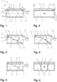
- Figure 1 shows a cross-sectional view of a passively operating mechanical functional unit 1 according to the invention for a shock wave protection valve 100 (see e.g Fig. 7 ) according to the invention.
- the functional unit 1 comprises a flow channel 2 which extends in a flow direction S (dash-dotted line) and is defined by boundary walls 3.
- the boundary walls 3 can form part of the functional unit 1 or can be provided, for example, by a housing 103 of the shock wave protection valve 100 (see Fig. 7 ), in which the functional unit 1 is arranged.
- the flow direction S corresponds to a longitudinal direction L.
- In the flow channel 2 there is a flow area 4 through which a ventilation stream can flow.
- a storage space 5 is also formed in the flow channel 2 next to the flow area 4.
- the storage space 5 is closed on one side in the longitudinal direction L by a closure 5.1 and is in the opposite direction open at an entry opening 5.2.
- the inlet opening 5.2 is directed opposite a blocking direction X, in which the passage of a shock wave through the functional unit 1 can be blocked.
- the blocking direction X denotes a direction parallel to the flow direction S in which an incoming shock wave propagates.
- the conclusion 5.1 of the storage space 5 in the blocking direction X is formed by a support 6 which extends along one of the boundary walls 3.
- a valve flap 7 is arranged between the flow area 4 and the storage space 5, which extends essentially parallel to the flow direction S.
- the valve flap 7 is attached to the support 6 with a foot area 7.1 and extends against the blocking direction remains.
- a free end 7.2 of the valve flap 7 is arranged at the inlet opening 5.2 of the storage space 5.
- the valve flap 7 limits the storage space 5 to the flow area 4 in a direction transverse to the flow direction S, which is referred to here as the height direction H and is defined by the direction transverse to the flow direction S or the longitudinal direction L in which the flow area 4, the valve flap 7 and the storage space 5 are arranged one above the other.
- the flow area 4 can be flowed through freely in both directions from S.
- the flow channel 2 has a height h 1 in the direction of H.
- the storage space 5 has a height h3 , which is essentially predetermined by the carrier 6.
- the carrier 6 closes with the valve flap 4 in a direction opposite to the direction H, ie it does not extend beyond the valve flap 7 into the flow area 4.
- the inlet opening 5.2 of the storage space 5 also has a height h 3 .
- the flow area 4 has a height h 2 which is significantly greater than the height h 3 of the storage space 5.
- a length l of the valve flap 7 in the longitudinal direction L is at least twice as large as the height h 2 of the flow area 4.
- Figure 2 shows schematically a top view of the functional unit 1 looking in the blocking direction While the flow area 4 can be freely flowed through in both directions in the flow direction S the storage space 5 is closed in the locking direction X by the closure 5.1 formed by the carrier 6.
- the valve flap 7 extends through the entire flow channel 2 in a direction perpendicular to the flow direction S, which is also perpendicular to H. This direction is referred to herein as the width direction B.
- the valve flap 7 thus divides the entire flow channel 2 into the flow area 4 and the storage space 5.
- a cross section transverse to the flow direction S of the flow channel 2 is thus essentially completely covered by the cross sections of the flow area 4 and storage space 5, apart from the end face of the free end 7.2 the valve flap 7.
- the storage space 5 is limited and closed by the boundary walls 3 arranged in the width direction B.
- Figure 3 shows the functional unit 1 in the event of a fault, in which the valve flap 7 is deflected into a closed position C in the flow area 4 due to a shock wave arriving in the blocking direction X.
- valve flap 7 is fastened to the carrier 6 with its foot area 7.1 via a joint 7.3 and is rigid.
- the joint 7.3 is spring-loaded (not shown) in such a way that the valve flap 7 is held in the open position O when there is no malfunction (see Fig. 1 ), and on the other hand is returned from the closed position C to the open position O after the fault has passed.
- valve flap 7 In the closed position C, the valve flap 7 is swung out into the closed position C about the hinge axis G arranged transversely to the flow direction S, in the width direction B.
- the free end 7.2 of the valve flap 7 rests on a boundary wall 3.1 opposite the open position O with respect to the flow area 4.
- the valve flap 7 is thus inclined at a substantially constant angle ⁇ with respect to the flow direction S (subject to any deflection due to the load). Since the length I of the valve flap 7 is preferably at least approximately twice as large as the height h 2 of the flow area 4, the angle ⁇ is not more than approximately 30°.
- valve flap 7 thus closes the flow area 4 over its entire cross section and forms one together with the end 5.1 of the storage space 5 Complete closure of the flow channel 2. A passage of the shock wave in the blocking direction X through the functional unit 1 is thus blocked.
- the deflection of the valve flap 7 from the open position O occurs due to an overpressure P building up in the storage space 5 as a result of the incoming shock wave.
- the overpressure P results from a flow associated with the incoming shock wave through the inlet opening 5.2 of the storage space 5. Due to the dynamic pressure of the inflow Due to the closure 5.1, a dynamic pressure can build up in the blocking direction In the flow area 4, however, no dynamic pressure is built up due to the same flow, since this is freely continuous. The resulting pressure difference between the flow area 4 and storage space 5 results in the overpressure P.
- This overpressure P acts on a surface of the valve flap 7 facing the storage space 5 and thus causes a force effect F P in a direction perpendicular to the surface of the valve flap 7.
- the force effect F P deflects the valve flap 7 into the flow area 4 and pushes it from the open position O into the closed position C. As the deflection increases, the valve flap 7 also offers an attack surface for the impact of the flow associated with the shock wave, which creates an additional force that supports the deflection the valve flap 7 causes.
- the illustrated embodiment of the functional unit 1 shows a valve flap 7 which is fixed, ie immovable, with its foot area 7.1 attached to the carrier 6 and which is designed to be elastically flexible, for example from a spring steel sheet. If there is no malfunction, the spring-elastic valve flap 7 is as in due to its nature Fig. 1 shown aligned in the flow direction S and held in the open position O.
- the spring-elastic valve flap 7 is pressed against the spring force transversely to the flow direction S from the open position O into the flow area 4 and into the closed position C. Due to the spring-elastic flexibility of the valve flap 7, it does not deflect in a straight line but rather curves towards the opposite boundary wall 3.1. The curvature increases in the representation of the Fig. 4 towards the boundary wall 3.1.
- a maximum angle of inclination ⁇ m with respect to the flow direction S of the valve flap 7 is reached at the free end 7.2.
- the angle ⁇ m is preferably a maximum of 45°, in particular only a maximum of 30°.
- Figure 5 shows a further embodiment of the functional unit 1, in which the valve flap 7 is fixed, ie immovable, with its foot area 7.1 attached to the carrier 6 and is designed to be resiliently flexible.
- the valve flap 7 is located in Fig. 5 in the open position O.
- Figure 6 shows a top view in the blocking direction of the functional unit Fig. 5 and is described together with this.
- the support ribs 8 are designed as slats which are aligned along the flow direction S and extend essentially over the entire length I of the valve flap 7.
- Each of the support ribs 8 has a support edge 8.1 directed towards the valve flap 7 and which slopes curved towards the boundary wall 3.1.
- a local inclination of the support edge 8.1 relative to the flow direction S towards the boundary wall 3.1 increases due to the curvature.
- the support ribs 8.1 are supported on the boundary wall 3.1, so that the forces exerted by the incoming shock wave on the valve flap 7 can be dissipated via the support ribs 8.1 to the boundary wall 3.1.
- the number of support ribs 8 and their spacing are adapted to the pressure impact requirements.
- FIG. 7 shows a shock wave protection valve 100 according to the invention with a tubular housing 103 with a rectangular cross section (not shown), in which two similar functional units 10 and 10 'are arranged parallel and mirror-symmetrically to one another with respect to a longitudinal plane F.
- the housing 103 has an air flow opening 110 and 111 at each longitudinal end in the longitudinal direction L, ie in the flow direction S.
- the air flow openings 110 and 111 connect to flow channels 12 and 12 'of the functional units 10 and 10'.
- a ball-like carrier 16 extends centrally in the housing 103 between two side walls (not shown) in the direction of the width B of the shock wave protection valve 100 with respect to the height direction H of the shock wave protection valve 100.
- the carrier 16 is at a distance seen in the blocking direction X Longitudinal end of the housing 103, arranged in the direction of H between the functional units 10 and 10 '.
- the carrier 16 is attached with its longitudinal ends to the side walls, not shown. All other components and their orientations of the functional units 10 and 10' essentially correspond to the components of the functional unit 1 Fig. 5 , wherein the arrangements and orientations of the components of the functional units 10 and 10 'are mirrored to one another with respect to a longitudinal plane F in which the carrier 16 extends and which is aligned along the flow direction S.
- valve flaps 17 and 17 'of the functional units 10 and 10' are attached to the support 16 in a mirror-symmetrical manner with foot areas 17.1 and 17.1' in the height direction H transverse to the flow direction S, on both sides with respect to the longitudinal plane F.
- the valve flaps 17 and 17 'extend in the flow direction S largely parallel to one another, in the direction opposite to the blocking direction flow areas 14 and 14 'of the functional units 10 and 10' are arranged.
- Lamella-like support ribs 18 and 18 ' are arranged in the flow areas 14 and 14', aligned in the flow direction S.
- the support ribs 18 and 18' have support edges 18.1 and 18.1', which extend curved towards the boundary walls 103.1 and 103.1' of the housing 103 against the blocking direction X.
- the carrier 16 forms a closure 15.1 of the area between the valve flaps 17 and 17'.
- the storage space 15 thus forms a common storage space 15 of the two functional units 10 and 10 ⁇ . Due to the mirror-symmetrical arrangement of the two functional units 10 and 10 'with respect to the longitudinal plane F, structural synergies can be used to make the overall size of the shock wave valve 100 more compact or to be able to provide the largest possible effective cross section of the flow areas 14 and 14' for a given size . It It is understood that the valve flaps 17 and 17 'and the flow areas 14 and 14' extend in the width direction B essentially over the entire width between the side walls, not shown, of the housing 103, that is, also essentially over the entire width of the carrier 16. In In the width direction B, the storage space 15 is thus delimited and closed by the side walls, not shown.
- Figure 8 shows a shock wave protection valve 200 with a tubular housing 203 with a rectangular cross section (not shown), in which two similar functional units 20 and 20 ', arranged mirror-symmetrically with respect to a transverse plane E, are connected to one another in series.
- the shock wave protection valve 200 has two opposing blocking directions X and X 2 .
- the housing 203 has an air flow opening 210 and 211 at each longitudinal end in the flow direction S.
- the air flow openings 211 and 210 each connect to a flow end of flow channels 22 and 22 'of the functional units 20 and 20'.
- the flow channels 22 and 22 ' connect to one another in the housing 203 with their respective further flow ends.
- a ball-like carrier 26 extends between two opposite side walls (not shown) of the housing 203 adjacent to a boundary wall 203.2 of the housing 203 in the direction of the width B of the shock wave protection valve 200.
- the carrier 26 is in the longitudinal direction L in the middle of the housing 203, in the direction of L between the functional units 20 and 20 'arranged.
- the carrier 26 is attached with its longitudinal ends to the side walls, not shown.
- All other components and their orientations of the functional units 20 and 20' essentially correspond to the components of the functional unit 1 Fig. 5 , wherein the arrangements and orientations of the components of the functional units 20 and 20 'are mirrored to one another with respect to the transverse plane E in which the carrier 26 extends and which is aligned perpendicular to the flow direction S.
- valve flaps 27 and 27' of the functional units 20 and 20' are attached to the carrier 26 with foot areas 27.1 and 27.1'.
- the valve flaps 27 and 27 ' extend in the flow direction S from the foot areas 27.1 and 27.1' in opposite directions and delimit a storage space 25 and 25 'in the direction of H.
- the storage spaces 25 and 25' are each closed in the direction of X 1 and X 2 by the carrier 26 in the flow direction S.
- the valve flap 27 of the functional unit 20 extends against the blocking direction X 1 and the valve flap 27' extends against the blocking direction X 2 .
- the valve flaps 27 and 27 ' are designed as a continuous sheet in the longitudinal direction L, in particular as a continuous sheet metal. A length l' of the continuous sheet essentially corresponds to a length of the housing 203.
- the valve flaps 27 and 27' thus have a common foot area 27.1/27.1' with which they are fastened to the carrier 26.
- Flow areas 24 and 24' of the functional units 20 and 20' are arranged between the respective valve flap 27 and 27 'and a boundary wall 203.1 of the housing 203 opposite the boundary wall 203.2 in the height direction H.
- the flow areas 24 and 24 ' form a continuous flow area which connects the air flow openings 210 and 211 so that a ventilation flow can flow through them along the flow direction S.
- Lamella-like support ribs 28 and 28 ' are arranged in the flow areas 24 and 24', aligned in the flow direction S.
- the support ribs 28 and 28' have support edges 28.1 and 28.1', which extend in opposite directions along the longitudinal direction L and in each case opposite to the blocking direction X 1 and X 2 respectively
- Boundary wall 203.1 of the housing 203 extends curved.
- the support ribs 28 and 28' are designed as continuous slats, in particular as continuous sheets, which extend into both flow areas 24 and 24'.
- Figure 9 shows a shock wave protection valve 300 with a tubular housing 303 with a rectangular cross section (not shown), in which there are four similar functional units 30, 30 ', 30 "and 30 ', arranged in pairs in mirror symmetry with respect to the transverse plane E and the longitudinal plane F.
- the combination of the four functional units 30, 30', 30" and 30" will be referred to as unit 39.
- the shock wave protection valve 300 forms a functional combination of the in 7 and 8 Shock wave valves 100 and 200 shown here.
- a ball-like carrier 36 extends between two side walls (not shown) of the housing 303 in the direction of the width B of the shock wave protection valve 300.
- the carrier is arranged centrally with respect to the height direction H and the longitudinal direction L of the shock wave protection valve 300 .
- the carrier 36 is attached with its longitudinal ends to the side walls, not shown, of the housing 303.
- the valve flaps 37' and 37" and 37 and 37" are analogous to the valve flaps 27 and 27' Fig. 8 each designed as continuous sheets in the longitudinal direction L, in particular as continuous sheets.
- the continuous leaves are attached to the carrier 36 in a mirror-symmetrical manner on both sides with respect to the longitudinal plane F, in the height direction H transverse to the flow direction S.
- valve flaps 37' and 37" and 37 and 37" each extend in opposite directions with respect to the longitudinal direction L from common foot areas 37.1' and 37.1” and 37.1 and 37.1” in opposite directions, with the valve flap 37 and 37' opposing the blocking direction X 1 and the valve flaps 37" and 37′′′ extend counter to the blocking direction X 2 .
- Two storage spaces 35 and 35' are thus formed between the continuous leaves of the valve flaps 37, 37', 37" and 37', which are closed off from the carrier 36 in the longitudinal direction in the blocking direction X and X 2 respectively.
- the storage space 35 forms a common one Storage space for the functional units 30 and 30' while the storage space 35' forms a common storage space for the functional units 30" and 30".
- the storage spaces 35 and 35 ' are closed by the side walls, not shown, of the housing 303 in the direction of the width B (analogous to the illustration in Fig. 2 ).
- Flow areas 34, 34', 34" and 34” are formed between the continuous leaves of the valve flaps 30 and 30′′′ and 30′ and 30′′ and opposite boundary walls 303.1.
- the flow areas 34 and 34′′′ as well as 34′ and 34′′ are formed in pairs and are connected to one another in series.
- the support ribs 38.1 and 28.1′′′ as well as 38.1′ and 38.1′′ of adjoining flow areas are each designed as slats that are continuous in the longitudinal direction L.
- the serial arrangement of the functional units 30 'and 30' or 30 and 30' provides a shock wave protection valve 300, which can be blocked in both flow directions and, due to the parallel arrangement of the functional units 30 and 30' or 30' and 30', simultaneously has a relatively large effective cross section that can be flowed through. It is understood that the unit 39 formed by the four functional units 30, 30 ', 30 "and 30" can be present in multiple versions in a shock wave valve according to the invention, arranged in parallel to one another in terms of flow (see, for example, Fig. 10 to 14 ).
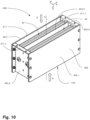
- FIGS 10 to 14 show views of a concrete implementation of a shock wave protection valve 400, in which two functional units 39 as in connection with Fig. 9 are described schematically, are arranged in parallel in terms of flow in a screwed housing 403. The Figures 10 to 14 are described together.
- FIG. 10 shows an external oblique view of the shock wave protection valve 400.
- the housing 403 has air flow openings 410 and 411 at the ends, the air flow opening 411 being provided with fastening flanges 411.1 for connection to, for example, a ventilation duct of a ventilation system.
- Two units 49 and 49 ' are arranged in an interior of the housing 403, each of which is designed essentially analogously to the unit 39 and will no longer be described in detail here.
- the unit 49 has four functional units 40.1 to 40.4 which are designed and arranged in the same way as the unit 39, while the unit 49 'has four functional units 40.1' to 40.4' (see e.g Fig. 13 ).
- the functional units 40.1 and 40.2 as well as 40.1' and 40.2' have a blocking direction X, while the functional units 40.3 and 40.4 as well as 40.3' and 40.4' have an opposite blocking direction X 2 .
- the two units 49 and 49 ' are delimited from one another by a partition 403.3, which extends halfway up in the direction of H over the entire width in the direction of B parallel to the flow direction S through the housing 403.
- Side walls 403.4 delimit the housing 403 in the direction of width B outside while the walls 403.1 limit the housing 403 in the direction from H to the outside.
- the units 49 and 49' are arranged one above the other in the direction of H and the partition 403.3 forms a boundary wall of the internal functional units 40.2, 40.3 as well as 40.2' and 40.3'.
- the two units 49 and 49' are designed to be mirror-symmetrical with respect to a plane defined by the partition 403.3.
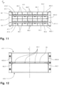
- FIG 11 shows a top view of the air flow opening 411 of the shock wave protection valve 400 in the direction of the blocking direction X 1 .
- Two supports 46 and 46' extend in the direction of width B transversely to the flow direction S through the entire housing 403 and are attached to the side walls 403.4.
- the carriers 46 and 46 ' are each arranged in the direction of H centrally between the partition 403.3 and the side walls 403.1 of the housing 403.
- continuous leaves of the valve flaps 47.1 to 47.4 and 47.1' to 47.4' of the functional units 40.1 to 40.4 and 40.1' to 40.4' are fastened on both sides of the carrier 46 and 46 '.
- the valve flaps 47.1 to 47.4 and 47.1 'to 47.4' are located in the Fig. 10 to 14 each in their open positions O.
- support ribs 48.1 to 48.4 and 48.1' to 48.4' in flow areas 44.1 to 44.4 and 44.1' to 44.4' of the functional units 40.1 to 40.4 and 40.1' to 40.4' are each designed as slats that are continuous in the longitudinal direction L.
- Figure 12 shows a cross section in a longitudinal plane in which the carrier 46 extends and which is aligned parallel to the longitudinal direction L.
- the ball-like carrier 46 (and similarly the carrier 46 ') is fastened in the housing 403 by direct axial screw connections 46.2, which protrude from the outside through the side walls 403.4. Bores 46.1 for fastening screws in the carrier 46 are used to fasten the support ribs 48.1 to 48.4 and the continuous leaves of the valve flaps 47.1 to 47.4.
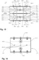
- Figure 13 shows a sectional view in a plane parallel to the longitudinal direction L and the height direction H.
- the free longitudinal ends of the valve flaps 47.1 to 47.4 and 47.1 'to 47.4' each have a closing edge 47.5, which is formed by a bend in the end region (example at the free ends the valve flaps 47.1 and 47.2).
- valve flaps 47.1 to 47.4 and 47.1' to 47.4' lie in their closed positions C on the walls 403.1 and the partition 403.3. Between the pairs of valve flaps 47.1 and 47.2 and 47.3 and 47.4 and also the pairs of valve flaps 47.1 'and 47.2' as well as 47.3' and 47.4', common storage spaces 45.1, 45.2, 45.3 and 45.4 are arranged for each pair
- Figure 14 shows an external view of the shock wave protection valve 400 on one of the side walls 403.4 along the width direction B.
- the screw connections 46.2 and 46.2 'of the supports 46 and 46' reaching from the outside through the side walls 403.4 can be seen.
- three fastening tongues 403.31 of the partition 403.3 can be seen, which engage in corresponding recesses in the side wall 403.3 and thus hold the partition 403.3 in the housing 403.
- Figure 15 shows schematically an embodiment of two similar pairs of supporting ribs 58, each connected via a fastening bridge 58.2.
- the pairs of supporting ribs 58 have rectilinear support edges 58.1 for a rigid valve flap (see e.g Fig. 3 ) when it is in the closed position C.
- the support ribs 58 are for an arrangement of two similar functional units connected in series, for example according to the embodiment of Fig. 9 provided, in which the support ribs extend in the flow direction S into both flow areas.
- the fastening bridge 58.2 has a through hole 58.3, which is intended for fastening in a shock wave protection valve, for example for screwing to a carrier 56 (indicated by dashed lines).
- the fastening bridge 58.2 defines a distance d between the individual support ribs of the pair of support ribs 58 in the width direction B.
- the two pairs of support ribs 58 are arranged at the same distance d from one another, so that a constant distance d of all support ribs results.
- Figure 16 shows schematically an embodiment of two pairs of support ribs 68, each connected via a fastening bridge 68.2, analogous to that Figure 15 with the difference that the support edges 68.1 are curved and have a gradient that varies along the flow direction S.
- Figure 17 shows schematically a further embodiment of three pairs of supporting ribs 68 each connected via a fastening bridge 68.2 as in Fig. 16 shown.
- supporting ribs facing each other adjacent pairs of supporting ribs 68 are arranged directly next to each other and screwed together via screw connections 68.4.
- the support ribs arranged directly next to one another can rest against one another or have an intermediate layer (not shown) which reinforces the support ribs. In this way, the structural stability of the support ribs can be improved by the screw connection and, if necessary, by the reinforcement layer. in Fig.
- valve flap leaf 67 There is also a continuous valve flap leaf 67 indicated by dashed lines, which is clamped between a carrier 66 (also dashed) and the fastening bridges 68.2 of the pairs of support ribs.
- the screw connections (not shown) that extend into the carrier 66 through the through holes 68.3 for fastening to the carrier 66 can therefore also be used to fasten the valve flap leaf 67.
- the valve flap leaf 67 has corresponding through holes for this purpose.
- Figure 18 shows a cross-sectional view of a further passively operating mechanical functional unit 50 according to the invention for a shock wave protection valve with stop ribs 59 in the storage space 55.
- the sectional plane of the Fig. 18 goes through one of the stop ribs 59.
- Figure 19 shows schematically a top view of the functional unit 50 looking in the blocking direction X. Figures 18 and 19 are described together below.
- the functional unit 50 is largely analogous to the functional unit 1 Fig. 1 formed and comprises a flow channel 52 extending in the flow direction S.
- a flow area 54 is present in the flow channel 52, through which a ventilation flow can flow and which is delimited by a valve flap 57 arranged in the flow direction in the flow channel 52 from a storage space 55 also arranged in the flow channel 52 is.
- stop elements 59 are arranged in the storage space 55, which are designed as stop ribs aligned in the flow direction S.
- the stop ribs 59 form stops for the valve flap 57, which in the open position O rests on stop edges 59.1 of the stop ribs 59 pointing towards the flow area 54.
- the valve flap 57 is spring-loaded in the direction of the storage space 55 in such a way that it is pressed against the stop edges 59.1 with a spring force.
- valve flap 57 is designed to be resiliently flexible, the preload can be achieved in that the valve flap 57 is designed to be angled towards the storage space 55 in a foot area 57.1 in the relaxed state. Ie in the absence of the stop ribs 59, the valve flap 57 would in this case, for example, protrude into the storage space 55 at an angle relative to the flow direction S, as in Fig. 18 indicated by dashed lines as position U. If the valve flap 57 is attached in an articulated manner, for example an additional spring element (not shown) or the spring element of the joint, which holds the valve flap 57 in the open position (O), can apply the preload.
- an additional spring element not shown
- the spring element of the joint which holds the valve flap 57 in the open position (O)
- the stop rib can extend in the common storage space and have stop edges on both sides in the height direction H, so that the two valve flaps rest on the same stop rib from both sides (not shown). If two functional units are connected to each other in series, such as in Fig. 8 shown, the stop ribs can extend as a continuous slat into both storage spaces of the two connected functional units (not shown).
- the passively operating mechanical functional unit according to the invention forms a versatile basic unit for a shock wave protection valve.
- essentially identical functional units can be arranged flow-wise in parallel and in series in a shock wave protection valve, so that a comparatively low flow resistance is achieved and yet the passage of a shock wave can be effectively blocked in one or both directions along a flow direction.
Landscapes
- Engineering & Computer Science (AREA)
- General Engineering & Computer Science (AREA)
- Mechanical Engineering (AREA)
- Health & Medical Sciences (AREA)
- Business, Economics & Management (AREA)
- Emergency Management (AREA)
- General Health & Medical Sciences (AREA)
- Public Health (AREA)
- Check Valves (AREA)
- Air-Flow Control Members (AREA)
Claims (15)
- Unité fonctionnelle mécanique (1, 10, 10') à fonctionnement passif, destinée à une soupape de protection (100, 200, 300) contre les ondes de choc, notamment d'un dispositif de ventilation, comprenant :a) un conduit d'écoulement (2, 12, 12'), pourvu d'une zone de passage (4, 14, 14'), laquelle est susceptible d'être traversée dans une direction d'écoulement (S) par un flux de ventilation et qui dans un cas de panne, est susceptible d'être bloquée dans une direction de fermeture (X), suite à une onde de choc se propageant dans la direction de fermeture (X),b) un clapet de soupape (7, 17, 17') de type lame, qui est maintenu dans une position d'ouverture (O) et qui dans un cas de panne, est susceptible d'être dévié par l'onde de choc au moins par endroits à la transversale de la direction d'écoulement (S) dans la zone de passage (4, 14, 14') dans une position de fermeture (C), dans laquelle la zone de passage (4,14,'14') est bloquée dans la direction de fermeture (X) par le clapet de soupape (7, 17, 17'),c) le clapet de soupape (7, 17, 17') étant placé entre un espace d'accumulation (5, 15), placé dans le conduit d'écoulement (2, 12, 12') et ouvert à l'encontre de la direction de fermeture (X) et la zone de passage (4, 14, 14'), de telle sorted) que dans le cas de panne, lors du passage de l'onde de choc dans l'espace d'accumulation (5, 15), une pression (P) puisse s'établir, laquelle pousse le clapet de soupape (7, 17, 17') au moins par endroits à la transversale de la direction d'écoulement(S) et le dévie dans la zone de passage (4, 14, 14'), de telle sorte que le clapet de soupape (7, 17, 17') arrive dans la position de fermeture (C), caractérisée en ce quee) dans la position d'ouverture (O), le clapet de soupape (7, 17, 17') est orienté sensiblement dans la direction d'écoulement (S).
- Unité fonctionnelle mécanique selon la revendication 1, caractérisée en ce que par une zone basse (7.1, 17.1, 17.1') dirigée dans la direction de fermeture (X), le clapet de soupape (7, 17, 17') est fixé dans le conduit d'écoulement (2, 12, 12') et s'étend de la zone basse (7.1, 17.1, 17.1') à l'encontre de la direction de fermeture (X).
- Unité fonctionnelle mécanique selon la revendication 2, caractérisée en ce que la zone basse (7.1, 17.1, 17.1') du clapet de soupape (7, 17, 17') est solidement fixée dans le conduit d'écoulement (2, 12, 12') et le clapet de soupape (7, 17, 17') est conçu au moins par endroits de manière flexible, notamment élastique, ou en ce que le clapet de soupape (7, 17, 17') est fixé par la zone basse (7.1, 17.1, 17.1'), de manière articulée, notamment résiliente dans le conduit d'écoulement (2, 12, 12').
- Unité fonctionnelle mécanique selon l'une quelconque des revendications 1 à 3, caractérisée en ce que dans la position d'ouverture (O), le clapet de soupape (7, 17, 17') est précontraint de manière résiliente vers l'espace d'accumulation (5, 15, 15'), au moins un élément de butée, sur lequel le clapet de soupape (7, 17, 17') s'appuie dans la position d'ouverture (O) étant conçu notamment dans l'espace d'accumulation (5, 15, 15').
- Unité fonctionnelle mécanique selon la revendication 1 à 4, caractérisée en ce qu'au moins deux, notamment au moins quatre, de préférence au moins huit nervures de soutien (8, 18, 18') orientées dans la direction d'écoulement (S), dont chacune comporte au moins une arête d'appui (8. 1, 18.1, 18.1') pour le clapet de soupape (7, 17, 17'), sur lesquelles le clapet de soupape (7, 17, 17') s'appuie dans la position de fermeture (C) sont placées dans la zone de passage (4, 14, 14').
- Unité fonctionnelle mécanique selon la revendication 5, caractérisée en ce que dans la direction de fermeture (X), les arêtes d'appui (8.1, 18.1, 18.1') des nervures de soutien (8, 18, 18') sont inclinées chacune dans la direction d'écoulement (S) et notamment un angle d'inclinaison (α) des arêtes d'appui (8.1, 18.1, 18.1') par rapport à la direction d'écoulement (S) est inférieur à 45°, de préférence inférieur à 30°.
- Unité fonctionnelle mécanique selon la revendication 6, caractérisée en ce que les arêtes d'appui (8.1, 18.1, 18.1') s'écoulent en étant recourbées avec un angle d'inclinaison (α) sans cesse croissant par rapport à la direction d'écoulement (S).
- Unité fonctionnelle mécanique selon l'une quelconque des revendications 1 à 7, caractérisée en ce que le clapet de soupape (7, 17, 17') présente une longueur (1) dans la direction d'écoulement (S) qui correspond au moins au double d'une hauteur (h2) de la zone de passage (4, 14, 14').
- Unité fonctionnelle mécanique selon l'une quelconque des revendications 1 à 8, caractérisée en ce que le clapet de soupape (7, 17, 17') constitue une paroi de délimitation de l'espace d'accumulation (5, 15) et / ou en ce que l'espace d'accumulation (5, 15) s'étend à la transversale de la direction d'écoulement (S), sensiblement sur une largeur totale du clapet de soupape (7, 17, 17') et / ou en ce que l'espace d'accumulation (5, 15) s'étend dans la direction d'écoulement (S) sensiblement sur toute la longueur (1) du clapet de soupape (7, 17, 17').
- Unité fonctionnelle mécanique selon l'une quelconque des revendications 1 à 9, caractérisée en ce que le clapet de soupape (7, 17, 17') s'étend à la transversale de la direction d'écoulement (S) sensiblement sur une largeur totale de la zone de passage (4, 14, 14'), de préférence sur une largeur totale du conduit d'écoulement (2, 12, 12'), et / ou en ce que l'espace d'accumulation (5, 15, 15') présente une hauteur inférieure à celle de la zone de passage (4, 14, 14').
- Soupape de protection (100, 200, 300) contre les ondes de choc, destinée à des dispositifs de ventilation, comprenant au moins une unité fonctionnelle mécanique (1, 10, 20) selon l'une quelconque des revendications 1 à 10, de préférence, l'au moins une unité fonctionnelle (1, 10, 20) étant placée dans un carter (103, 203, 303) pourvu de deux orifices (110, 111, 210, 211, 310, 311) de circulation d'air, lesquels sont reliés par le conduit d'écoulement (2, 12, 22) de l'unité fonctionnelle (1, 10, 20), notamment le carter (103, 203, 303) délimitant au moins partiellement le conduit d'écoulement (2, 12, 22) de l'au moins une unité fonctionnelle (1, 10, 20).
- Dispositif de ventilation, pourvu d'au moins un conduit de ventilation et d'au moins une soupape de protection (100, 200, 300, 400) contre les ondes de choc selon la revendication 11, raccordée sur celuici.
- Installation d'essai, pourvue d'un générateur d'ondes de choc et d'une soupape de protection (100, 200, 300, 400) contre les ondes de choc selon la revendication 11.
- Procédé, destiné à mesurer une pression de fermeture et / ou une résistance à l'écoulement d'une soupape de protection (100, 200, 300, 400) contre les ondes de choc selon la revendication 11, comprenant les étapes consistant àa) insérer la soupape de protection (100, 200, 300, 400) contre les ondes de choc dans un tube à ondes de choc ;b) créer un flux d'air constant dans le tube à ondes de choc ;c) déterminer une valeur de mesure du flux d'air ;d) créer un onde de choc dans le tube à ondes de choc ;e) déterminer une valeur de mesure pour la chute de pression ;f) comparer la valeur de mesure avec des valeurs prédéfinies, pour constater si la soupape de protection contre les ondes de choc se ferme.
- Utilisation (100, 200, 300, 400) d'une soupape de protection contre les ondes de choc selon la revendication 11 dans un laboratoire d'essai pour déterminer des protections antidéflagrantes.
Applications Claiming Priority (2)
| Application Number | Priority Date | Filing Date | Title |
|---|---|---|---|
| CH00132/20A CH717113A8 (de) | 2020-02-05 | 2020-02-05 | Passiv arbeitende mechanische Funktionseinheit für ein Stosswellenschutzventil und Stosswellenschutzventil. |
| PCT/EP2021/052316 WO2021156206A1 (fr) | 2020-02-05 | 2021-02-01 | Unité fonctionnelle mécanique à fonctionnement passif pour soupape de protection contre les ondes de choc, et soupape de protection contre les ondes de choc associée |
Publications (3)
| Publication Number | Publication Date |
|---|---|
| EP4100673A1 EP4100673A1 (fr) | 2022-12-14 |
| EP4100673B1 true EP4100673B1 (fr) | 2024-01-31 |
| EP4100673C0 EP4100673C0 (fr) | 2024-01-31 |
Family
ID=69779693
Family Applications (1)
| Application Number | Title | Priority Date | Filing Date |
|---|---|---|---|
| EP21703195.4A Active EP4100673B1 (fr) | 2020-02-05 | 2021-02-01 | Unité fonctionnelle mécanique à fonctionnement passif pour soupape de protection contre les ondes de choc, et soupape de protection contre les ondes de choc associée |
Country Status (6)
| Country | Link |
|---|---|
| EP (1) | EP4100673B1 (fr) |
| CN (1) | CN115053093B (fr) |
| CA (1) | CA3165788A1 (fr) |
| CH (1) | CH717113A8 (fr) |
| SA (1) | SA522440048B1 (fr) |
| WO (1) | WO2021156206A1 (fr) |
Families Citing this family (2)
| Publication number | Priority date | Publication date | Assignee | Title |
|---|---|---|---|---|
| CN113944791B (zh) * | 2021-11-23 | 2024-11-05 | 上海爵格工业工程有限公司 | 双向抗爆阀 |
| CN118862335B (zh) * | 2024-06-24 | 2025-04-29 | 武汉理工大学 | 一种舷间冲击波定向开关结构及其设计方法 |
Family Cites Families (5)
| Publication number | Priority date | Publication date | Assignee | Title |
|---|---|---|---|---|
| US3139108A (en) * | 1962-09-24 | 1964-06-30 | Klingman Sanford | Pressure operated valve means |
| CN105333189B (zh) * | 2015-11-24 | 2018-05-04 | 江苏爵格工业设备有限公司 | 抗冲击波阀 |
| DE202016004209U1 (de) * | 2016-04-06 | 2016-07-22 | Rexotec Ag | Druckentlastungsvorrichtung zur explosionsmäßigen Entkopplung zweier Anlagenteile |
| CN106195379B (zh) * | 2016-09-13 | 2019-03-19 | 江苏省安全生产科学研究院 | 感应冲击波的无源快速自动切断阀 |
| CN106885026B (zh) * | 2017-03-17 | 2020-07-31 | 江苏爵格工业设备有限公司 | 一种常闭式单向隔爆阀 |
-
2020
- 2020-02-05 CH CH00132/20A patent/CH717113A8/de unknown
-
2021
- 2021-02-01 CA CA3165788A patent/CA3165788A1/fr active Pending
- 2021-02-01 EP EP21703195.4A patent/EP4100673B1/fr active Active
- 2021-02-01 WO PCT/EP2021/052316 patent/WO2021156206A1/fr not_active Ceased
- 2021-02-01 CN CN202180012842.7A patent/CN115053093B/zh active Active
-
2022
- 2022-08-04 SA SA522440048A patent/SA522440048B1/ar unknown
Also Published As
| Publication number | Publication date |
|---|---|
| CA3165788A1 (fr) | 2021-08-12 |
| CH717113A1 (de) | 2021-08-16 |
| SA522440048B1 (ar) | 2024-08-29 |
| CN115053093A (zh) | 2022-09-13 |
| EP4100673A1 (fr) | 2022-12-14 |
| CH717113A8 (de) | 2022-01-31 |
| WO2021156206A1 (fr) | 2021-08-12 |
| CN115053093B (zh) | 2025-07-08 |
| EP4100673C0 (fr) | 2024-01-31 |
Similar Documents
| Publication | Publication Date | Title |
|---|---|---|
| EP4100673B1 (fr) | Unité fonctionnelle mécanique à fonctionnement passif pour soupape de protection contre les ondes de choc, et soupape de protection contre les ondes de choc associée | |
| EP2724071A1 (fr) | Fermeture à lamelles et élément élastique pour une fermeture à lamelles | |
| EP2870350B1 (fr) | Dispositif de clapet de retenue pour moteur à combustion interne | |
| DE202004010819U1 (de) | Volumenstromregler, insbesondere für klima- und lüftungstechnische Anlagen | |
| EP0478100B1 (fr) | Dispositif d'arrêt pour une conduite à gaz | |
| DE102013112912A1 (de) | Stützpfosten für eine Wand oder einen Zaun sowie Wand oder Zaun und Wand-Zaun-Kombination | |
| DE3716234C2 (fr) | ||
| EP2655908B1 (fr) | Chariot de guidage à vanne de lubrifiant | |
| DE102013100310A1 (de) | Riegelstange für einen Riegelstangenbeschlag | |
| EP4067594A1 (fr) | Ferrure de jonction | |
| EP2787265B1 (fr) | Pièce de cornière d'angle | |
| DE2810118A1 (de) | Absperr- und drosselarmatur | |
| EP1092899B1 (fr) | Dispositif d'étanchéité | |
| DE202019106957U1 (de) | Einbauschrankanordnung | |
| DE202014102436U1 (de) | Abdeckung für eine Entwässerungsrinne | |
| DE2820208C2 (de) | Absperrvorrichtung, insbesondere Druckentlastungsjalousie | |
| DE19823310A1 (de) | Verbundwasserzähler | |
| EP2146156B1 (fr) | Clapet de saute de pression | |
| EP0616179B1 (fr) | Dispositif d'obturation d'un passage d'air | |
| EP1030986B1 (fr) | Dispositif pour realiser une etancheite | |
| DE2236103C3 (de) | LuftauslaB für Lüftungsanlagen | |
| EP4230903B1 (fr) | Dispositif de fixation de tuyaux ou de conduits | |
| EP1130334B1 (fr) | Régulateur de débit en particulier pour les installations de conditionnement d'air | |
| DE102005020185B4 (de) | Ventilanordnung | |
| AT519365B1 (de) | Energiespeicher |
Legal Events
| Date | Code | Title | Description |
|---|---|---|---|
| STAA | Information on the status of an ep patent application or granted ep patent |
Free format text: STATUS: UNKNOWN |
|
| STAA | Information on the status of an ep patent application or granted ep patent |
Free format text: STATUS: THE INTERNATIONAL PUBLICATION HAS BEEN MADE |
|
| PUAI | Public reference made under article 153(3) epc to a published international application that has entered the european phase |
Free format text: ORIGINAL CODE: 0009012 |
|
| STAA | Information on the status of an ep patent application or granted ep patent |
Free format text: STATUS: REQUEST FOR EXAMINATION WAS MADE |
|
| 17P | Request for examination filed |
Effective date: 20220826 |
|
| AK | Designated contracting states |
Kind code of ref document: A1 Designated state(s): AL AT BE BG CH CY CZ DE DK EE ES FI FR GB GR HR HU IE IS IT LI LT LU LV MC MK MT NL NO PL PT RO RS SE SI SK SM TR |
|
| DAV | Request for validation of the european patent (deleted) | ||
| DAX | Request for extension of the european patent (deleted) | ||
| GRAP | Despatch of communication of intention to grant a patent |
Free format text: ORIGINAL CODE: EPIDOSNIGR1 |
|
| STAA | Information on the status of an ep patent application or granted ep patent |
Free format text: STATUS: GRANT OF PATENT IS INTENDED |
|
| INTG | Intention to grant announced |
Effective date: 20230925 |
|
| GRAS | Grant fee paid |
Free format text: ORIGINAL CODE: EPIDOSNIGR3 |
|
| GRAA | (expected) grant |
Free format text: ORIGINAL CODE: 0009210 |
|
| STAA | Information on the status of an ep patent application or granted ep patent |
Free format text: STATUS: THE PATENT HAS BEEN GRANTED |
|
| AK | Designated contracting states |
Kind code of ref document: B1 Designated state(s): AL AT BE BG CH CY CZ DE DK EE ES FI FR GB GR HR HU IE IS IT LI LT LU LV MC MK MT NL NO PL PT RO RS SE SI SK SM TR |
|
| REG | Reference to a national code |
Ref country code: GB Ref legal event code: FG4D Free format text: NOT ENGLISH Ref country code: CH Ref legal event code: EP |
|
| REG | Reference to a national code |
Ref country code: DE Ref legal event code: R096 Ref document number: 502021002579 Country of ref document: DE |
|
| REG | Reference to a national code |
Ref country code: IE Ref legal event code: FG4D Free format text: LANGUAGE OF EP DOCUMENT: GERMAN |
|
| U01 | Request for unitary effect filed |
Effective date: 20240209 |
|
| U07 | Unitary effect registered |
Designated state(s): AT BE BG DE DK EE FI FR IT LT LU LV MT NL PT SE SI Effective date: 20240220 |
|
| U20 | Renewal fee for the european patent with unitary effect paid |
Year of fee payment: 4 Effective date: 20240223 |
|
| PG25 | Lapsed in a contracting state [announced via postgrant information from national office to epo] |
Ref country code: GR Free format text: LAPSE BECAUSE OF FAILURE TO SUBMIT A TRANSLATION OF THE DESCRIPTION OR TO PAY THE FEE WITHIN THE PRESCRIBED TIME-LIMIT Effective date: 20240501 |
|
| PG25 | Lapsed in a contracting state [announced via postgrant information from national office to epo] |
Ref country code: RS Free format text: LAPSE BECAUSE OF FAILURE TO SUBMIT A TRANSLATION OF THE DESCRIPTION OR TO PAY THE FEE WITHIN THE PRESCRIBED TIME-LIMIT Effective date: 20240430 Ref country code: HR Free format text: LAPSE BECAUSE OF FAILURE TO SUBMIT A TRANSLATION OF THE DESCRIPTION OR TO PAY THE FEE WITHIN THE PRESCRIBED TIME-LIMIT Effective date: 20240131 |
|
| PG25 | Lapsed in a contracting state [announced via postgrant information from national office to epo] |
Ref country code: ES Free format text: LAPSE BECAUSE OF FAILURE TO SUBMIT A TRANSLATION OF THE DESCRIPTION OR TO PAY THE FEE WITHIN THE PRESCRIBED TIME-LIMIT Effective date: 20240131 |
|
| PG25 | Lapsed in a contracting state [announced via postgrant information from national office to epo] |
Ref country code: RS Free format text: LAPSE BECAUSE OF FAILURE TO SUBMIT A TRANSLATION OF THE DESCRIPTION OR TO PAY THE FEE WITHIN THE PRESCRIBED TIME-LIMIT Effective date: 20240430 Ref country code: HR Free format text: LAPSE BECAUSE OF FAILURE TO SUBMIT A TRANSLATION OF THE DESCRIPTION OR TO PAY THE FEE WITHIN THE PRESCRIBED TIME-LIMIT Effective date: 20240131 Ref country code: GR Free format text: LAPSE BECAUSE OF FAILURE TO SUBMIT A TRANSLATION OF THE DESCRIPTION OR TO PAY THE FEE WITHIN THE PRESCRIBED TIME-LIMIT Effective date: 20240501 Ref country code: ES Free format text: LAPSE BECAUSE OF FAILURE TO SUBMIT A TRANSLATION OF THE DESCRIPTION OR TO PAY THE FEE WITHIN THE PRESCRIBED TIME-LIMIT Effective date: 20240131 |
|
| PG25 | Lapsed in a contracting state [announced via postgrant information from national office to epo] |
Ref country code: PL Free format text: LAPSE BECAUSE OF FAILURE TO SUBMIT A TRANSLATION OF THE DESCRIPTION OR TO PAY THE FEE WITHIN THE PRESCRIBED TIME-LIMIT Effective date: 20240131 |
|
| PG25 | Lapsed in a contracting state [announced via postgrant information from national office to epo] |
Ref country code: PL Free format text: LAPSE BECAUSE OF FAILURE TO SUBMIT A TRANSLATION OF THE DESCRIPTION OR TO PAY THE FEE WITHIN THE PRESCRIBED TIME-LIMIT Effective date: 20240131 |
|
| PG25 | Lapsed in a contracting state [announced via postgrant information from national office to epo] |
Ref country code: SM Free format text: LAPSE BECAUSE OF FAILURE TO SUBMIT A TRANSLATION OF THE DESCRIPTION OR TO PAY THE FEE WITHIN THE PRESCRIBED TIME-LIMIT Effective date: 20240131 |
|
| PG25 | Lapsed in a contracting state [announced via postgrant information from national office to epo] |
Ref country code: CZ Free format text: LAPSE BECAUSE OF FAILURE TO SUBMIT A TRANSLATION OF THE DESCRIPTION OR TO PAY THE FEE WITHIN THE PRESCRIBED TIME-LIMIT Effective date: 20240131 |
|
| PG25 | Lapsed in a contracting state [announced via postgrant information from national office to epo] |
Ref country code: SK Free format text: LAPSE BECAUSE OF FAILURE TO SUBMIT A TRANSLATION OF THE DESCRIPTION OR TO PAY THE FEE WITHIN THE PRESCRIBED TIME-LIMIT Effective date: 20240131 |
|
| PG25 | Lapsed in a contracting state [announced via postgrant information from national office to epo] |
Ref country code: SM Free format text: LAPSE BECAUSE OF FAILURE TO SUBMIT A TRANSLATION OF THE DESCRIPTION OR TO PAY THE FEE WITHIN THE PRESCRIBED TIME-LIMIT Effective date: 20240131 Ref country code: SK Free format text: LAPSE BECAUSE OF FAILURE TO SUBMIT A TRANSLATION OF THE DESCRIPTION OR TO PAY THE FEE WITHIN THE PRESCRIBED TIME-LIMIT Effective date: 20240131 Ref country code: RO Free format text: LAPSE BECAUSE OF FAILURE TO SUBMIT A TRANSLATION OF THE DESCRIPTION OR TO PAY THE FEE WITHIN THE PRESCRIBED TIME-LIMIT Effective date: 20240131 Ref country code: CZ Free format text: LAPSE BECAUSE OF FAILURE TO SUBMIT A TRANSLATION OF THE DESCRIPTION OR TO PAY THE FEE WITHIN THE PRESCRIBED TIME-LIMIT Effective date: 20240131 |
|
| REG | Reference to a national code |
Ref country code: DE Ref legal event code: R097 Ref document number: 502021002579 Country of ref document: DE |
|
| PG25 | Lapsed in a contracting state [announced via postgrant information from national office to epo] |
Ref country code: MC Free format text: LAPSE BECAUSE OF FAILURE TO SUBMIT A TRANSLATION OF THE DESCRIPTION OR TO PAY THE FEE WITHIN THE PRESCRIBED TIME-LIMIT Effective date: 20240131 |
|
| PG25 | Lapsed in a contracting state [announced via postgrant information from national office to epo] |
Ref country code: MC Free format text: LAPSE BECAUSE OF FAILURE TO SUBMIT A TRANSLATION OF THE DESCRIPTION OR TO PAY THE FEE WITHIN THE PRESCRIBED TIME-LIMIT Effective date: 20240131 |
|
| PLBE | No opposition filed within time limit |
Free format text: ORIGINAL CODE: 0009261 |
|
| STAA | Information on the status of an ep patent application or granted ep patent |
Free format text: STATUS: NO OPPOSITION FILED WITHIN TIME LIMIT |
|
| 26N | No opposition filed |
Effective date: 20241101 |
|
| PG25 | Lapsed in a contracting state [announced via postgrant information from national office to epo] |
Ref country code: IE Free format text: LAPSE BECAUSE OF NON-PAYMENT OF DUE FEES Effective date: 20240201 |
|
| PG25 | Lapsed in a contracting state [announced via postgrant information from national office to epo] |
Ref country code: IE Free format text: LAPSE BECAUSE OF NON-PAYMENT OF DUE FEES Effective date: 20240201 |
|
| U20 | Renewal fee for the european patent with unitary effect paid |
Year of fee payment: 5 Effective date: 20250221 |
|
| PGFP | Annual fee paid to national office [announced via postgrant information from national office to epo] |
Ref country code: IS Payment date: 20250211 Year of fee payment: 5 |
|
| PGFP | Annual fee paid to national office [announced via postgrant information from national office to epo] |
Ref country code: NO Payment date: 20250221 Year of fee payment: 5 |
|
| PGFP | Annual fee paid to national office [announced via postgrant information from national office to epo] |
Ref country code: CH Payment date: 20250301 Year of fee payment: 5 |
|
| PGFP | Annual fee paid to national office [announced via postgrant information from national office to epo] |
Ref country code: GB Payment date: 20250220 Year of fee payment: 5 |
|
| PGFP | Annual fee paid to national office [announced via postgrant information from national office to epo] |
Ref country code: TR Payment date: 20250129 Year of fee payment: 5 |
|
| PG25 | Lapsed in a contracting state [announced via postgrant information from national office to epo] |
Ref country code: CY Free format text: LAPSE BECAUSE OF FAILURE TO SUBMIT A TRANSLATION OF THE DESCRIPTION OR TO PAY THE FEE WITHIN THE PRESCRIBED TIME-LIMIT; INVALID AB INITIO Effective date: 20210201 |
|
| PG25 | Lapsed in a contracting state [announced via postgrant information from national office to epo] |
Ref country code: HU Free format text: LAPSE BECAUSE OF FAILURE TO SUBMIT A TRANSLATION OF THE DESCRIPTION OR TO PAY THE FEE WITHIN THE PRESCRIBED TIME-LIMIT; INVALID AB INITIO Effective date: 20210201 |