EP4100673B1 - Passively operating mechanical functional unit for a shock wave protection valve, and shock wave protection valve - Google Patents
Passively operating mechanical functional unit for a shock wave protection valve, and shock wave protection valve Download PDFInfo
- Publication number
- EP4100673B1 EP4100673B1 EP21703195.4A EP21703195A EP4100673B1 EP 4100673 B1 EP4100673 B1 EP 4100673B1 EP 21703195 A EP21703195 A EP 21703195A EP 4100673 B1 EP4100673 B1 EP 4100673B1
- Authority
- EP
- European Patent Office
- Prior art keywords
- flow
- shock wave
- valve flap
- valve
- functional unit
- Prior art date
- Legal status (The legal status is an assumption and is not a legal conclusion. Google has not performed a legal analysis and makes no representation as to the accuracy of the status listed.)
- Active
Links
Images


Classifications
-
- F—MECHANICAL ENGINEERING; LIGHTING; HEATING; WEAPONS; BLASTING
- F16—ENGINEERING ELEMENTS AND UNITS; GENERAL MEASURES FOR PRODUCING AND MAINTAINING EFFECTIVE FUNCTIONING OF MACHINES OR INSTALLATIONS; THERMAL INSULATION IN GENERAL
- F16K—VALVES; TAPS; COCKS; ACTUATING-FLOATS; DEVICES FOR VENTING OR AERATING
- F16K17/00—Safety valves; Equalising valves, e.g. pressure relief valves
- F16K17/006—Safety valves; Equalising valves, e.g. pressure relief valves specially adapted for shelters
-
- A—HUMAN NECESSITIES
- A62—LIFE-SAVING; FIRE-FIGHTING
- A62B—DEVICES, APPARATUS OR METHODS FOR LIFE-SAVING
- A62B13/00—Special devices for ventilating gasproof shelters
-
- A—HUMAN NECESSITIES
- A62—LIFE-SAVING; FIRE-FIGHTING
- A62C—FIRE-FIGHTING
- A62C4/00—Flame traps allowing passage of gas but not of flame or explosion wave
-
- F—MECHANICAL ENGINEERING; LIGHTING; HEATING; WEAPONS; BLASTING
- F16—ENGINEERING ELEMENTS AND UNITS; GENERAL MEASURES FOR PRODUCING AND MAINTAINING EFFECTIVE FUNCTIONING OF MACHINES OR INSTALLATIONS; THERMAL INSULATION IN GENERAL
- F16K—VALVES; TAPS; COCKS; ACTUATING-FLOATS; DEVICES FOR VENTING OR AERATING
- F16K17/00—Safety valves; Equalising valves, e.g. pressure relief valves
- F16K17/20—Excess-flow valves
- F16K17/22—Excess-flow valves actuated by the difference of pressure between two places in the flow line
- F16K17/24—Excess-flow valves actuated by the difference of pressure between two places in the flow line acting directly on the cutting-off member
- F16K17/28—Excess-flow valves actuated by the difference of pressure between two places in the flow line acting directly on the cutting-off member operating in one direction only
Definitions
- the invention relates to a passively operating mechanical functional unit for a shock wave protection valve, in particular for a ventilation system, a flow channel with a flow area through which a ventilation stream can flow in a flow direction and which can be blocked in a blocking direction in the event of a fault as a result of a shock wave propagating in the blocking direction .
- the functional unit further comprises a leaf-like valve flap which is held in an open position and which, in the event of a fault, can be deflected by the shock wave at least in sections transversely to the flow direction into the flow area into a closed position, in which the flow area is blocked in the blocking direction by the valve flap.
- the invention also relates to a shock wave protection valve comprising such a functional unit as well as a ventilation system and a testing system with such a shock valve.
- the invention further relates to a method for measuring a closing pressure and/or a flow resistance of such a shock wave protection valve and its use in a testing laboratory.
- shock wave protection valves are primarily used in areas where ventilation is required, but there is a risk that people or systems could be damaged as a result of compressed air surges.
- shock wave protection valves are used as pressure wave protection for the supply and exhaust air openings of ventilation ducts of shelters for people or systems, containments for nuclear power plants, offshore systems or military buildings.
- Shock wave protection valves offer effective protection against the effects of pressure waves from, for example, nuclear or conventional detonations and prevent them Propagation of the pressure wave into the ventilation ducts of the ventilation system or out of the ventilation ducts.
- Active shock wave protection valves require external energy and a control system for pressure-safe closure. With the help of sensors, they register the increase in pressure caused by the incoming shock wave and then use an actuator to trigger the closure of the valve.
- Passive shock wave protection valves function without external energy or control, react only to the effect of the shock wave and, due to their structural nature, prevent pressure from spreading within the pipelines and into adjacent parts of the system.
- Such a passive shock wave protection valve in a supply air or exhaust air duct of a boiler in the military sector is, for example, from US 3,139,108 known.
- This has several elastic valve plates, which are arranged between adjacent passage openings for an air flow. In the open position, the valve plates protrude obliquely outwards with respect to a flow direction into the incoming or outgoing air flow.
- the valve flaps are bent into a closed position on the passage openings, so that they are closed. After the shock wave has passed through, the elastic valve plates automatically return to the open position.
- valve plates have to protrude into the air flow with a considerable inclination so that there is sufficient surface area for the shock wave to attack.
- this is accompanied by considerable flow resistance.
- valve plates have to be bent relatively strongly out of the open position in order to close them, which creates the risk of undesirable plastic deformation and requires special, cost-intensive materials for the valve plates.
- the application relates to the military sector and is therefore not easily and economically applicable in a civil sector, for example.
- DE202016004209U1 discloses a passively operating mechanical functional unit according to the preamble of claim 1.
- the object of the invention is therefore to create a passively operating mechanical functional unit for a shock wave protection valve and a shock wave protection valve belonging to the technical field mentioned at the beginning, which Overcome disadvantages of the prior art.
- a further object of the invention is to provide a method for measuring a closing pressure and/or a flow resistance and a use of such a shock wave protection valve.
- a passively operating mechanical functional unit for a shock wave protection valve in particular for a ventilation system, comprises a flow channel with a flow area through which a ventilation flow can flow in a flow direction and which can be blocked in a blocking direction in the event of a fault as a result of a shock wave propagating in the blocking direction is.
- the functional unit further comprises a leaf-like valve flap which is held in an open position and which, in the event of a fault, can be deflected by the shock wave at least in sections transversely to the flow direction into the flow area into a closed position, in which the flow area is blocked by the valve flap in the blocking direction.
- the functional unit is characterized in that the valve flap is essentially aligned in the flow direction in the open position and is arranged between a storage space arranged in the flow channel and open against the blocking direction and the flow area in such a way that in the event of a malfunction when the shock wave passes through the shock wave in the storage space a pressure can be built up, which presses the valve flap at least in sections transversely to the direction of flow and deflects it into the flow area, so that the valve flap reaches the closed position.
- One dimension in the direction of flow is referred to here as “length”, while two dimensions aligned perpendicular to the direction of flow and perpendicular to each other are referred to as “width” and “height”.
- the height refers to the dimension in the direction in which the valve flap is arranged between the storage space and the flow area.
- the “flow channel” refers to a section of the functional unit that extends in the direction of flow and extends essentially over its length in the longitudinal direction on both sides Has openings extending across the entire end cross section.
- the cross section of the flow channel can be constant or change in the direction of flow.
- the cross section can fundamentally be round or polygonal, in particular rectangular.
- the ventilation flow can flow through the openings over its entire end cross section.
- the flow channel is enclosed by one or more boundary walls and is delimited by them perpendicular to the direction of flow.
- the “flow area” refers to an area of the flow channel through which the ventilation flow can flow largely unhindered in the direction of flow if there is no malfunction.
- the flow area forms a partial area of the flow channel and has an effective cross section which is continuous in the flow direction over the entire length of the flow channel for the ventilation flow if there is no malfunction.
- a malfunction occurs when, for example, as a result of a detonation or deflagration, a pressure or shock wave occurs in the ventilation flow, which the functional unit is designed and designed to block. If there is no malfunction during operation, this is referred to as normal operation.
- valve flap-like refers to a design of the valve flap as a plate with two main surfaces, which are delimited by circumferential, relatively thin edges.
- the valve flap can be made, for example, from a sheet metal such as a stainless steel sheet.
- the valve flap can be deflected at least in sections transversely to the flow direction into the flow area.
- the valve flap can, for example, be designed to be rigid and pivotable about a pivot axis, or it can be designed to be flexible and deflected at least in sections into the flow area by bending.
- the “open position” refers to a position of the valve flap in which it is arranged in the normal state, in particular in normal operation.
- the valve flap In the open position, the valve flap is essentially aligned in the flow direction, ie the main surfaces of the valve flap are arranged essentially parallel to the flow direction.
- essentially parallel can include minor deviations from a parallel position, which can amount to up to 15°.
- the effective cross section of the flow area is therefore not or only slightly reduced or blocked by the valve flap when it is in the open position.
- the “closed position” refers to a position of the valve flap in which the flow area of the valve flap is essentially completely closed, so that the ventilation flow can no longer flow through it, at least in the blocking direction. It goes without saying that there is no need for a hermetic seal in the closed position. It is important that in the closed position the flow area is blocked for the passage of a sufficiently strong pressure wave in the ventilation flow, in particular a shock wave.
- blocking direction refers to the direction in which the functional unit can block the passage of a shock wave.
- the blocking direction can be directed in the same direction or in the opposite direction to the flow direction, depending on whether the functional unit is intended for use in the sense of a pressure valve or in the sense of a check valve.
- the storage space is designed in the flow channel next to the valve flap in such a way that the valve flap is arranged between the flow area and the storage space.
- the storage space defines a storage volume in the flow channel and covers a portion of the cross section of the flow channel through which the ventilation flow flows.
- the storage space is at least partially open, so that the storage volume defined by the storage space communicates with the ventilation flow.
- the storage space is essentially closed off from the rest of the flow channel, in particular from the flow area, and thus forms a non-flowable storage area in the flow channel.
- the storage space can be closed off, for example, by boundary walls, in particular, for example, a housing of a shock wave protection valve or separate partition walls provided for this purpose.
- a dynamic pressure is built up in the storage space, in contrast to the continuous flow area. This creates a pressure difference between the storage space and the flow area, ie an overpressure in the storage space, which acts on the valve flap arranged between them.
- the valve flap is designed to be deflectable in such a way that the excess pressure must exceed a certain threshold value so that the valve flap is deflected from the open position into the closed position.
- the Threshold value for the overpressure defines a transition from normal operation to a fault.
- the valve flap By arranging the valve flap between the storage space and the flow area according to the invention, the excess pressure built up in the storage space can act directly and over a large area on the valve flap. With a comparatively small flow cross-section of the storage space, a comparatively large force can be exerted on the valve flap. In this way it is achieved that, with low flow resistance, the valve flap is reliably deflected into the flow area in the event of a malfunction and reaches the closed position.
- the pressure of the shock wave arriving in the blocking direction is converted by the storage space into a force transverse to the flow direction on the valve flap.
- the valve flap does not need to have an attack surface directed towards the incoming shock wave in the open position for deflection, i.e. no angle of attack with respect to the direction of flow is required.
- the valve flap can be arranged aligned in the flow direction in the open position. This means that the valve flap does not protrude into the flow area in the open position and does not impair the effective cross section of the flow area in favor of low flow resistance.
- the valve flap is held in the open position, i.e. is fastened in such a way that in the absence of external forces, the valve flap remains in the open position, which means that no flow energy is or has to be taken from the ventilation flow as it flows through to keep it open.
- a structurally simple functional unit for a shock wave protection valve, which has a reliable blocking property and a comparatively low flow resistance.
- the functional unit according to the invention is preferably used for room ventilation.
- the functional unit is particularly suitable for low-pressure applications in which a ventilation flow in normal operation has a pressure, for example, of the order of around 200 Pa and in the event of a fault, a pressure, for example, in the range of around 300 Pa.
- the invention is particularly suitable for applications in which the pressure loss in the valve is a maximum of 600 Pa during normal operation.
- the valve flap can be deflected resiliently into the closed position.
- the valve flap is preferably resiliently deflectable in such a way that a restoring force is exerted on the valve flap, which returns it from a deflected position, in particular the closed position, to the open position.
- the resiliently deflectable valve flap can be achieved by making the valve flap resiliently flexible, for example at least in some areas or as a whole.
- the valve flap can be designed to be rigid and can be deflected via a spring-loaded hinge or joint. Of course, combinations of spring-loaded joints and spring-elastic valve flaps are also conceivable.
- valve flap can be designed to be plastically deformable at least in some areas, so that the valve flap is permanently deformed in the course of deflection and remains in the closed position after a fault.
- functional units require maintenance work or replacement of the valve flap after a malfunction.
- the valve flap is preferably fastened in the flow channel with a foot area directed in the blocking direction and extends from the foot area counter to the blocking direction.
- the valve flap has a certain angle of attack with respect to the flow direction, at least partially, and can therefore be detected by an inflow associated with the incoming shock wave. Due to the associated redirection of a portion of the flow at the valve flap, an additional force is generated on the valve flap, which supports or accelerates the transition to the closed position.
- the foot area of the valve flap is firmly fastened in the flow channel and the valve flap is designed to be flexible at least in some areas.
- the deflection of the valve flap is achieved through its flexibility. This has the advantage that the deflection of the valve flap does not require any moving parts that require maintenance and can lose functionality over time, for example due to contamination or corrosion.
- the valve flap is designed to be resiliently flexible, so that it is automatically returned to the open position after a malfunction.
- valve flap articulated in the foot area
- the foot area of the valve flap can be attached in an articulated manner in the flow channel.
- the entire valve flap can be deflected around the joint.
- attachment via a joint does not exclude the fact that the valve flap can also be flexible, in particular resiliently flexible.
- the valve flap is preferably attached in a resiliently articulated manner, i.e. the joint is spring-loaded in order to automatically return the valve flap to the open position after a malfunction.
- the valve flap preferably has a closing edge at a free end pointing counter to the blocking direction, with which it rests against a boundary wall of the flow area in the closed position.
- the boundary wall against which the valve flap rests in the closed position is generally opposite the valve flap in terms of the flow area when it is in the open position.
- the closing element forms a defined contact surface of the valve flap for contact with the boundary wall.
- the closing edge can, for example, be formed by an angled area at the free end of the valve flap, with which the valve flap lies flat against the boundary wall in the inclined closed position for better sealing. The angled area can also help stiffen the free end of the valve flap.
- a seat can also be formed on the boundary wall, in which the closing edge is arranged for better sealing in the closed position.
- the valve flap is resiliently biased towards the storage space in the open position, with at least one stop element being formed, in particular in the storage space, against which the valve flap rests in the open position. In the open position, the valve flap is thus pressed against the stop element by the resilient preload.
- the stop element is designed such that the valve flap is aligned in the direction of flow when it rests against it in the open position. The stop element prevents the valve flap from being deflected from the open position into the storage space.
- the stop element can comprise a stop rib aligned in the direction of flow with a stop edge against which the valve flap rests. Pin-like or block-like elements are also conceivable, which prevent the valve flap from being deflected into the storage space.
- the stop element can, for example, be attached to a boundary wall or to a support to which the valve flap is attached (see below).
- the resilient preload causes a spring force to act on the valve flap towards the storage space.
- the functional unit can include an additional spring element or, if present, the same spring element can apply the spring load towards the storage space, which enables the valve flap to be deflected resiliently into the flow area.
- this itself can be designed in such a way that a spring force acts towards the storage space in the open position.
- the valve flap can, for example, be designed to be angled towards the storage space in such a way that in the relaxed state, that is to say if the stop element were not present, it is at least partially deflected into the storage space.
- the valve flap can be angled towards the storage space at the foot area.
- valve flap in this particular embodiment is resiliently biased towards the storage space and rests against the stop element in the open position, the valve flap is not completely free and it can be prevented that the valve flap During normal operation, the ventilation flow causes undesirable oscillations or deflects it into the storage space.
- the spring load can be adapted to the specific conditions of the air flow.
- the mechanical functional unit therefore preferably comprises at least two support ribs aligned in the flow direction and arranged in the flow area, each of which has at least one support edge for the valve flap and against which the valve flap can rest in the closed position.
- the support edges are preferably arranged next to one another at a distance from one another in the width direction and are designed in such a way that they support the valve flap in the closed position against the blocking direction. In the closed position, the valve flap preferably rests with one of its main surfaces on the support edges.
- the support ribs preferably have a constant distance in the width direction. More preferably, the support ribs are connected to one another in pairs via a fastening bridge, in particular U-shaped in cross section, whereby two support ribs can be mounted in the flow channel via the one fastening bridge.
- the supporting ribs connected in pairs increase the structural stability of the supporting ribs. Adjacent pairs of supporting ribs connected in pairs can be screwed together on the adjacent supporting ribs, for example with a stabilizing intermediate layer, in order to further increase the structural stability.
- the pairs of supporting ribs connected via the fastening bridge can be made, for example, as a stamped and bent part from a sheet of metal, in particular a stainless steel sheet.
- valve flap in the closed position the valve flap is advantageously inclined in the blocking direction relative to the flow direction in order to be able to absorb the forces acting due to an incoming shock wave particularly well in the event of a malfunction.
- the support edges of the support ribs are therefore also advantageously inclined in the blocking direction relative to the flow direction. In this way, the support edges can optimally support the valve flap deflected into the flow area in the inclined closed position.
- the angle of inclination of the support edges is preferably less than 45°, preferably less than 30°, which supports the valve flap in a particularly resistant orientation in the closed position.
- the support edges preferably extend up to a boundary wall of the flow area, which is opposite the valve flap with respect to the flow area when the valve flap is in the open position.
- the support edges are curved with a constantly increasing angle of inclination relative to the direction of flow.
- a flexible valve flap can thus rest against the support edges during the transition to the closed position from the foot area to the free end with an increasing inclination upstream. Due to the curvature, an even contact can be achieved without the flexible valve flap buckling.
- spring-elastic valve flaps it can be prevented that in the event of a fault an elasticity range is exceeded and the valve flap is plastically deformed.
- the valve flap has a length in the flow direction which is at least twice as large as a height of the flow area.
- the height of the flow area refers to the greatest vertical distance between the valve flap in the open position and an opposite boundary wall of the flow area.
- the valve flap forms a boundary wall of the storage space, especially in the open position.
- the valve flap preferably forms a boundary wall of the storage space facing the flow area and preferably at the same time a boundary wall of the flow area facing the storage space.
- the further boundary walls of the storage space can be formed, for example, by boundary walls of the flow channel or by separate wall elements and are preferably designed to be rigid and unchangeable.
- the valve flap forms a variable boundary wall of the storage space, the storage volume of which changes during the deflection of the valve flap, i.e. during the transition from the open position to the closed position.
- the storage space In order to develop the greatest possible force on the valve flap, the storage space, according to a preferred embodiment, extends transversely to the flow direction essentially over the entire width of the valve flap. In this way, the force resulting from the excess pressure that can build up in the storage space can act across the entire width of the valve flap. For the same reasons, it is also advantageous if the storage space extends essentially over the entire length of the valve flap in the direction of flow. In this way, the force acting on the valve flap can be maximized.
- the storage space can in principle also be designed to be less wide or less long than the valve flap, for example if that is to be expected in the event of a malfunction Increase in pressure would lead to excessive force if it were to act on the entire main surface of the valve flap.
- valve flap extends transversely to the flow direction essentially over an entire width of the flow area. In this way it can be ensured that the flow area can be completely closed by the valve flap.
- the valve flap and in particular the flow area preferably extend over the entire width of the flow channel. In this way, the flow channel can be optimally utilized, which ultimately enables a compact size of the functional unit.
- the storage space has a lower height than the flow area. In this way, for a given cross section of the flow channel, the effective cross section of the flow area can be relatively large, while the storage space only takes up a small proportion of the inlet cross section of the flow channel.
- the flow direction is aligned with the blocking direction in an intended operation.
- the passage of a pressure or shock wave in the direction of the flowing air stream can be blocked, so that the functional unit is suitable for use as a pressure valve.
- the flow direction is opposite to the blocking direction in an intended operation.
- the passage of a pressure or shock wave can be blocked against the direction of the flowing air stream, so that the functional unit is suitable for use as a check valve.
- the invention also relates to a shock wave protection valve for ventilation systems comprising at least one mechanical functional unit, which is initially defined as a solution to the problem and which can have further optional features.
- the at least one functional unit is preferably arranged in a housing with two air flow openings, which are connected by the flow channel of the at least one functional unit.
- the housing is advantageously intended as a duct installation component for installation in a ventilation duct of a ventilation system.
- the shock wave protection valve can be connected to the ventilation duct with one or both air flow openings or inserted into it, so that the ventilation flow can flow into the flow duct of the at least one functional unit and flow through the flow area.
- the housing preferably has fastening means such as fastening flanges or tabs for screw connections in the area of one or both air flow openings.
- the housing can be designed in accordance with relevant standards in order to be able to be integrated into existing standardized ventilation systems.
- the housing can also at least partially limit the flow channel of the at least one functional unit and possibly also its flow area, which enables a simplified construction.
- the shock wave protection valve comprises at least one further, similar functional unit, which is arranged parallel to the at least one functional unit.
- a ventilation flow entering the shock wave protection valve can flow to both flow channels of the functional units.
- the functional units can be designed as modules, for example, so that the shock wave valve is easily scalable and adaptable to different needs.
- more than two similar functional units can be provided in a parallel arrangement.
- the storage spaces of the at least one and the at least one further functional unit form a common storage space which is arranged between the valve flaps of the at least one and the at least one further functional unit.
- the valve flaps preferably delimit the storage space transversely to the flow direction on two opposite sides transversely to the flow direction, so that the most direct possible force effect is achieved due to the excess pressure that can be built up in the storage space.
- shock wave protection valve more than two, in particular 4 or 8, functional units arranged in parallel can be provided in the shock wave protection valve, each of which has a common storage space in pairs. In this way, the size of the shock wave valve can be made more compact or, for a given size, the largest possible effective cross section of the available flow areas can be provided.
- valve flaps of the at least one and the at least one further functional unit can preferably be attached with a respective foot area to a common carrier, in particular arranged transversely to the flow direction between the functional units.
- the common support can be designed, for example, as a crossbar with, for example, a rectangular cross-section, which extends through the housing essentially over the entire width.
- the common carrier preferably also forms a conclusion to the common storage space.
- the common carrier has a height which essentially corresponds to the height of the storage space.
- the foot areas of the two valve flaps can, for example, be attached to two sides of the carrier that are opposite in the height direction, so that the storage space is limited by the valve flaps and the carrier.
- each of the functional units is preferably provided with a further functional unit in the shock wave protection valve, which is designed to be mirror-symmetrical with respect to a plane transverse to the direction of flow and is connected in series.
- the flow areas of each pair of serially connected functional units preferably communicate with one another and completely overlap each other and form a continuous flow area. Due to the mirror-symmetrical design of the functional units, the blocking directions of the serially connected functional units are opposite to one another. During operation, however, the air flow flows through the serially connected functional units in the same intended flow direction.
- each pair of functional units connected in series preferably has at least 2, in particular at least 4, preferably at least 8, common support ribs which are continuous in the direction of flow and which each have support edges for the valve flaps of the functional units of the pair.
- the support ribs of the pair of functional units can be designed, for example, as continuous guide surfaces, which simplifies the construction.
- the continuous support ribs can be designed to be connected to one another in pairs via a fastening bridge, in particular in a U-shape, whereby two continuous support ribs can be mounted in the flow channel via the one fastening bridge.
- the support ribs are preferably attached to the above-mentioned common carrier, to which the valve flaps of the functional units arranged in parallel are also attached.
- the continuous support ribs connected in pairs via the fastening bridge can be made as a stamped and bent part from a sheet metal, in particular a stainless steel sheet.
- valve flaps of each pair of serially connected functional units are preferably a common sheet that is continuous in the direction of flow, in particular as a continuous sheet Stainless steel sheet, formed.
- the valve flaps which in this case are designed to be flexible, in particular resiliently flexible, can thus be manufactured in one piece in a simple manner.
- a longitudinally central region of the continuous sheet metal can form a common foot region of the two valve flaps, from which the valve flaps extend in opposite directions along the flow direction.
- the common foot area is preferably attached to the above-mentioned common support, to which the valve flaps of the parallel functional units and/or the continuous support ribs are also attached.
- Ventilation system according to the invention:
- the invention also relates to a ventilation system with at least one ventilation duct and at least one shock wave valve connected to it, as described here.
- the ventilation system can be intended for room ventilation, for example in residential or office buildings, or as a technical ventilation system, for example for recooling, or for supply air to diesel generators, or in nuclear power plants, in refinery plants or on oil rigs.
- the invention also relates to a testing system with a shock wave generator and a shock wave protection valve as described herein.
- the testing system is preferably used to check a closing pressure and/or a flow resistance of the shock wave valve.
- the testing system preferably includes a ventilation duct through which the shock wave protection valve is connected to the shock wave generator.
- the shock wave generator can be used to generate a shock wave, which propagates through the ventilation duct and enters the shock wave valve in the blocking direction.
- the testing system can also have an air flow generator, which generates an air flow in the ventilation duct, which flows through the shock wave valve and corresponds to an intended normal operation.
- the testing system preferably has one or more sensors with which a pressure drop at the shock wave protection valve can be measured.
- At least one pressure sensor is preferably present upstream and downstream of the shock wave protection valve.
- measured values determined by the sensors can be evaluated and, for example, compared with predetermined values or values determined during normal operation in order to determine whether the shock wave protection valve closes as intended in the event of a malfunction.
- the evaluation unit can be designed for this purpose from those determined during normal operation Measured values to determine a flow resistance of the shock wave protection valve and to use the determined flow resistance as a comparison value for a flow resistance in the event of a malfunction.
- the method according to the invention is preferably carried out on a testing system according to the invention.
- shock wave protection valve Use of the shock wave protection valve according to the invention:
- the invention also relates to the use of a shock wave protection valve as described herein in a testing laboratory for explosion protection regulations.
- the use in a testing laboratory for explosion protection regulations can include the use of a testing system according to the invention as described herein.
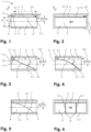
- Figure 1 shows a cross-sectional view of a passively operating mechanical functional unit 1 according to the invention for a shock wave protection valve 100 (see e.g Fig. 7 ) according to the invention.
- the functional unit 1 comprises a flow channel 2 which extends in a flow direction S (dash-dotted line) and is defined by boundary walls 3.
- the boundary walls 3 can form part of the functional unit 1 or can be provided, for example, by a housing 103 of the shock wave protection valve 100 (see Fig. 7 ), in which the functional unit 1 is arranged.
- the flow direction S corresponds to a longitudinal direction L.
- In the flow channel 2 there is a flow area 4 through which a ventilation stream can flow.
- a storage space 5 is also formed in the flow channel 2 next to the flow area 4.
- the storage space 5 is closed on one side in the longitudinal direction L by a closure 5.1 and is in the opposite direction open at an entry opening 5.2.
- the inlet opening 5.2 is directed opposite a blocking direction X, in which the passage of a shock wave through the functional unit 1 can be blocked.
- the blocking direction X denotes a direction parallel to the flow direction S in which an incoming shock wave propagates.
- the conclusion 5.1 of the storage space 5 in the blocking direction X is formed by a support 6 which extends along one of the boundary walls 3.
- a valve flap 7 is arranged between the flow area 4 and the storage space 5, which extends essentially parallel to the flow direction S.
- the valve flap 7 is attached to the support 6 with a foot area 7.1 and extends against the blocking direction remains.
- a free end 7.2 of the valve flap 7 is arranged at the inlet opening 5.2 of the storage space 5.
- the valve flap 7 limits the storage space 5 to the flow area 4 in a direction transverse to the flow direction S, which is referred to here as the height direction H and is defined by the direction transverse to the flow direction S or the longitudinal direction L in which the flow area 4, the valve flap 7 and the storage space 5 are arranged one above the other.
- the flow area 4 can be flowed through freely in both directions from S.
- the flow channel 2 has a height h 1 in the direction of H.
- the storage space 5 has a height h3 , which is essentially predetermined by the carrier 6.
- the carrier 6 closes with the valve flap 4 in a direction opposite to the direction H, ie it does not extend beyond the valve flap 7 into the flow area 4.
- the inlet opening 5.2 of the storage space 5 also has a height h 3 .
- the flow area 4 has a height h 2 which is significantly greater than the height h 3 of the storage space 5.
- a length l of the valve flap 7 in the longitudinal direction L is at least twice as large as the height h 2 of the flow area 4.
- Figure 2 shows schematically a top view of the functional unit 1 looking in the blocking direction While the flow area 4 can be freely flowed through in both directions in the flow direction S the storage space 5 is closed in the locking direction X by the closure 5.1 formed by the carrier 6.
- the valve flap 7 extends through the entire flow channel 2 in a direction perpendicular to the flow direction S, which is also perpendicular to H. This direction is referred to herein as the width direction B.
- the valve flap 7 thus divides the entire flow channel 2 into the flow area 4 and the storage space 5.
- a cross section transverse to the flow direction S of the flow channel 2 is thus essentially completely covered by the cross sections of the flow area 4 and storage space 5, apart from the end face of the free end 7.2 the valve flap 7.
- the storage space 5 is limited and closed by the boundary walls 3 arranged in the width direction B.
- Figure 3 shows the functional unit 1 in the event of a fault, in which the valve flap 7 is deflected into a closed position C in the flow area 4 due to a shock wave arriving in the blocking direction X.
- valve flap 7 is fastened to the carrier 6 with its foot area 7.1 via a joint 7.3 and is rigid.
- the joint 7.3 is spring-loaded (not shown) in such a way that the valve flap 7 is held in the open position O when there is no malfunction (see Fig. 1 ), and on the other hand is returned from the closed position C to the open position O after the fault has passed.
- valve flap 7 In the closed position C, the valve flap 7 is swung out into the closed position C about the hinge axis G arranged transversely to the flow direction S, in the width direction B.
- the free end 7.2 of the valve flap 7 rests on a boundary wall 3.1 opposite the open position O with respect to the flow area 4.
- the valve flap 7 is thus inclined at a substantially constant angle ⁇ with respect to the flow direction S (subject to any deflection due to the load). Since the length I of the valve flap 7 is preferably at least approximately twice as large as the height h 2 of the flow area 4, the angle ⁇ is not more than approximately 30°.
- valve flap 7 thus closes the flow area 4 over its entire cross section and forms one together with the end 5.1 of the storage space 5 Complete closure of the flow channel 2. A passage of the shock wave in the blocking direction X through the functional unit 1 is thus blocked.
- the deflection of the valve flap 7 from the open position O occurs due to an overpressure P building up in the storage space 5 as a result of the incoming shock wave.
- the overpressure P results from a flow associated with the incoming shock wave through the inlet opening 5.2 of the storage space 5. Due to the dynamic pressure of the inflow Due to the closure 5.1, a dynamic pressure can build up in the blocking direction In the flow area 4, however, no dynamic pressure is built up due to the same flow, since this is freely continuous. The resulting pressure difference between the flow area 4 and storage space 5 results in the overpressure P.
- This overpressure P acts on a surface of the valve flap 7 facing the storage space 5 and thus causes a force effect F P in a direction perpendicular to the surface of the valve flap 7.
- the force effect F P deflects the valve flap 7 into the flow area 4 and pushes it from the open position O into the closed position C. As the deflection increases, the valve flap 7 also offers an attack surface for the impact of the flow associated with the shock wave, which creates an additional force that supports the deflection the valve flap 7 causes.
- the illustrated embodiment of the functional unit 1 shows a valve flap 7 which is fixed, ie immovable, with its foot area 7.1 attached to the carrier 6 and which is designed to be elastically flexible, for example from a spring steel sheet. If there is no malfunction, the spring-elastic valve flap 7 is as in due to its nature Fig. 1 shown aligned in the flow direction S and held in the open position O.
- the spring-elastic valve flap 7 is pressed against the spring force transversely to the flow direction S from the open position O into the flow area 4 and into the closed position C. Due to the spring-elastic flexibility of the valve flap 7, it does not deflect in a straight line but rather curves towards the opposite boundary wall 3.1. The curvature increases in the representation of the Fig. 4 towards the boundary wall 3.1.
- a maximum angle of inclination ⁇ m with respect to the flow direction S of the valve flap 7 is reached at the free end 7.2.
- the angle ⁇ m is preferably a maximum of 45°, in particular only a maximum of 30°.
- Figure 5 shows a further embodiment of the functional unit 1, in which the valve flap 7 is fixed, ie immovable, with its foot area 7.1 attached to the carrier 6 and is designed to be resiliently flexible.
- the valve flap 7 is located in Fig. 5 in the open position O.
- Figure 6 shows a top view in the blocking direction of the functional unit Fig. 5 and is described together with this.
- the support ribs 8 are designed as slats which are aligned along the flow direction S and extend essentially over the entire length I of the valve flap 7.
- Each of the support ribs 8 has a support edge 8.1 directed towards the valve flap 7 and which slopes curved towards the boundary wall 3.1.
- a local inclination of the support edge 8.1 relative to the flow direction S towards the boundary wall 3.1 increases due to the curvature.
- the support ribs 8.1 are supported on the boundary wall 3.1, so that the forces exerted by the incoming shock wave on the valve flap 7 can be dissipated via the support ribs 8.1 to the boundary wall 3.1.
- the number of support ribs 8 and their spacing are adapted to the pressure impact requirements.
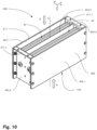
- FIG. 7 shows a shock wave protection valve 100 according to the invention with a tubular housing 103 with a rectangular cross section (not shown), in which two similar functional units 10 and 10 'are arranged parallel and mirror-symmetrically to one another with respect to a longitudinal plane F.
- the housing 103 has an air flow opening 110 and 111 at each longitudinal end in the longitudinal direction L, ie in the flow direction S.
- the air flow openings 110 and 111 connect to flow channels 12 and 12 'of the functional units 10 and 10'.
- a ball-like carrier 16 extends centrally in the housing 103 between two side walls (not shown) in the direction of the width B of the shock wave protection valve 100 with respect to the height direction H of the shock wave protection valve 100.
- the carrier 16 is at a distance seen in the blocking direction X Longitudinal end of the housing 103, arranged in the direction of H between the functional units 10 and 10 '.
- the carrier 16 is attached with its longitudinal ends to the side walls, not shown. All other components and their orientations of the functional units 10 and 10' essentially correspond to the components of the functional unit 1 Fig. 5 , wherein the arrangements and orientations of the components of the functional units 10 and 10 'are mirrored to one another with respect to a longitudinal plane F in which the carrier 16 extends and which is aligned along the flow direction S.
- valve flaps 17 and 17 'of the functional units 10 and 10' are attached to the support 16 in a mirror-symmetrical manner with foot areas 17.1 and 17.1' in the height direction H transverse to the flow direction S, on both sides with respect to the longitudinal plane F.
- the valve flaps 17 and 17 'extend in the flow direction S largely parallel to one another, in the direction opposite to the blocking direction flow areas 14 and 14 'of the functional units 10 and 10' are arranged.
- Lamella-like support ribs 18 and 18 ' are arranged in the flow areas 14 and 14', aligned in the flow direction S.
- the support ribs 18 and 18' have support edges 18.1 and 18.1', which extend curved towards the boundary walls 103.1 and 103.1' of the housing 103 against the blocking direction X.
- the carrier 16 forms a closure 15.1 of the area between the valve flaps 17 and 17'.
- the storage space 15 thus forms a common storage space 15 of the two functional units 10 and 10 ⁇ . Due to the mirror-symmetrical arrangement of the two functional units 10 and 10 'with respect to the longitudinal plane F, structural synergies can be used to make the overall size of the shock wave valve 100 more compact or to be able to provide the largest possible effective cross section of the flow areas 14 and 14' for a given size . It It is understood that the valve flaps 17 and 17 'and the flow areas 14 and 14' extend in the width direction B essentially over the entire width between the side walls, not shown, of the housing 103, that is, also essentially over the entire width of the carrier 16. In In the width direction B, the storage space 15 is thus delimited and closed by the side walls, not shown.
- Figure 8 shows a shock wave protection valve 200 with a tubular housing 203 with a rectangular cross section (not shown), in which two similar functional units 20 and 20 ', arranged mirror-symmetrically with respect to a transverse plane E, are connected to one another in series.
- the shock wave protection valve 200 has two opposing blocking directions X and X 2 .
- the housing 203 has an air flow opening 210 and 211 at each longitudinal end in the flow direction S.
- the air flow openings 211 and 210 each connect to a flow end of flow channels 22 and 22 'of the functional units 20 and 20'.
- the flow channels 22 and 22 ' connect to one another in the housing 203 with their respective further flow ends.
- a ball-like carrier 26 extends between two opposite side walls (not shown) of the housing 203 adjacent to a boundary wall 203.2 of the housing 203 in the direction of the width B of the shock wave protection valve 200.
- the carrier 26 is in the longitudinal direction L in the middle of the housing 203, in the direction of L between the functional units 20 and 20 'arranged.
- the carrier 26 is attached with its longitudinal ends to the side walls, not shown.
- All other components and their orientations of the functional units 20 and 20' essentially correspond to the components of the functional unit 1 Fig. 5 , wherein the arrangements and orientations of the components of the functional units 20 and 20 'are mirrored to one another with respect to the transverse plane E in which the carrier 26 extends and which is aligned perpendicular to the flow direction S.
- valve flaps 27 and 27' of the functional units 20 and 20' are attached to the carrier 26 with foot areas 27.1 and 27.1'.
- the valve flaps 27 and 27 ' extend in the flow direction S from the foot areas 27.1 and 27.1' in opposite directions and delimit a storage space 25 and 25 'in the direction of H.
- the storage spaces 25 and 25' are each closed in the direction of X 1 and X 2 by the carrier 26 in the flow direction S.
- the valve flap 27 of the functional unit 20 extends against the blocking direction X 1 and the valve flap 27' extends against the blocking direction X 2 .
- the valve flaps 27 and 27 ' are designed as a continuous sheet in the longitudinal direction L, in particular as a continuous sheet metal. A length l' of the continuous sheet essentially corresponds to a length of the housing 203.
- the valve flaps 27 and 27' thus have a common foot area 27.1/27.1' with which they are fastened to the carrier 26.
- Flow areas 24 and 24' of the functional units 20 and 20' are arranged between the respective valve flap 27 and 27 'and a boundary wall 203.1 of the housing 203 opposite the boundary wall 203.2 in the height direction H.
- the flow areas 24 and 24 ' form a continuous flow area which connects the air flow openings 210 and 211 so that a ventilation flow can flow through them along the flow direction S.
- Lamella-like support ribs 28 and 28 ' are arranged in the flow areas 24 and 24', aligned in the flow direction S.
- the support ribs 28 and 28' have support edges 28.1 and 28.1', which extend in opposite directions along the longitudinal direction L and in each case opposite to the blocking direction X 1 and X 2 respectively
- Boundary wall 203.1 of the housing 203 extends curved.
- the support ribs 28 and 28' are designed as continuous slats, in particular as continuous sheets, which extend into both flow areas 24 and 24'.
- Figure 9 shows a shock wave protection valve 300 with a tubular housing 303 with a rectangular cross section (not shown), in which there are four similar functional units 30, 30 ', 30 "and 30 ', arranged in pairs in mirror symmetry with respect to the transverse plane E and the longitudinal plane F.
- the combination of the four functional units 30, 30', 30" and 30" will be referred to as unit 39.
- the shock wave protection valve 300 forms a functional combination of the in 7 and 8 Shock wave valves 100 and 200 shown here.
- a ball-like carrier 36 extends between two side walls (not shown) of the housing 303 in the direction of the width B of the shock wave protection valve 300.
- the carrier is arranged centrally with respect to the height direction H and the longitudinal direction L of the shock wave protection valve 300 .
- the carrier 36 is attached with its longitudinal ends to the side walls, not shown, of the housing 303.
- the valve flaps 37' and 37" and 37 and 37" are analogous to the valve flaps 27 and 27' Fig. 8 each designed as continuous sheets in the longitudinal direction L, in particular as continuous sheets.
- the continuous leaves are attached to the carrier 36 in a mirror-symmetrical manner on both sides with respect to the longitudinal plane F, in the height direction H transverse to the flow direction S.
- valve flaps 37' and 37" and 37 and 37" each extend in opposite directions with respect to the longitudinal direction L from common foot areas 37.1' and 37.1” and 37.1 and 37.1” in opposite directions, with the valve flap 37 and 37' opposing the blocking direction X 1 and the valve flaps 37" and 37′′′ extend counter to the blocking direction X 2 .
- Two storage spaces 35 and 35' are thus formed between the continuous leaves of the valve flaps 37, 37', 37" and 37', which are closed off from the carrier 36 in the longitudinal direction in the blocking direction X and X 2 respectively.
- the storage space 35 forms a common one Storage space for the functional units 30 and 30' while the storage space 35' forms a common storage space for the functional units 30" and 30".
- the storage spaces 35 and 35 ' are closed by the side walls, not shown, of the housing 303 in the direction of the width B (analogous to the illustration in Fig. 2 ).
- Flow areas 34, 34', 34" and 34” are formed between the continuous leaves of the valve flaps 30 and 30′′′ and 30′ and 30′′ and opposite boundary walls 303.1.
- the flow areas 34 and 34′′′ as well as 34′ and 34′′ are formed in pairs and are connected to one another in series.
- the support ribs 38.1 and 28.1′′′ as well as 38.1′ and 38.1′′ of adjoining flow areas are each designed as slats that are continuous in the longitudinal direction L.
- the serial arrangement of the functional units 30 'and 30' or 30 and 30' provides a shock wave protection valve 300, which can be blocked in both flow directions and, due to the parallel arrangement of the functional units 30 and 30' or 30' and 30', simultaneously has a relatively large effective cross section that can be flowed through. It is understood that the unit 39 formed by the four functional units 30, 30 ', 30 "and 30" can be present in multiple versions in a shock wave valve according to the invention, arranged in parallel to one another in terms of flow (see, for example, Fig. 10 to 14 ).
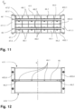
- FIGS 10 to 14 show views of a concrete implementation of a shock wave protection valve 400, in which two functional units 39 as in connection with Fig. 9 are described schematically, are arranged in parallel in terms of flow in a screwed housing 403. The Figures 10 to 14 are described together.
- FIG. 10 shows an external oblique view of the shock wave protection valve 400.
- the housing 403 has air flow openings 410 and 411 at the ends, the air flow opening 411 being provided with fastening flanges 411.1 for connection to, for example, a ventilation duct of a ventilation system.
- Two units 49 and 49 ' are arranged in an interior of the housing 403, each of which is designed essentially analogously to the unit 39 and will no longer be described in detail here.
- the unit 49 has four functional units 40.1 to 40.4 which are designed and arranged in the same way as the unit 39, while the unit 49 'has four functional units 40.1' to 40.4' (see e.g Fig. 13 ).
- the functional units 40.1 and 40.2 as well as 40.1' and 40.2' have a blocking direction X, while the functional units 40.3 and 40.4 as well as 40.3' and 40.4' have an opposite blocking direction X 2 .
- the two units 49 and 49 ' are delimited from one another by a partition 403.3, which extends halfway up in the direction of H over the entire width in the direction of B parallel to the flow direction S through the housing 403.
- Side walls 403.4 delimit the housing 403 in the direction of width B outside while the walls 403.1 limit the housing 403 in the direction from H to the outside.
- the units 49 and 49' are arranged one above the other in the direction of H and the partition 403.3 forms a boundary wall of the internal functional units 40.2, 40.3 as well as 40.2' and 40.3'.
- the two units 49 and 49' are designed to be mirror-symmetrical with respect to a plane defined by the partition 403.3.
- FIG 11 shows a top view of the air flow opening 411 of the shock wave protection valve 400 in the direction of the blocking direction X 1 .
- Two supports 46 and 46' extend in the direction of width B transversely to the flow direction S through the entire housing 403 and are attached to the side walls 403.4.
- the carriers 46 and 46 ' are each arranged in the direction of H centrally between the partition 403.3 and the side walls 403.1 of the housing 403.
- continuous leaves of the valve flaps 47.1 to 47.4 and 47.1' to 47.4' of the functional units 40.1 to 40.4 and 40.1' to 40.4' are fastened on both sides of the carrier 46 and 46 '.
- the valve flaps 47.1 to 47.4 and 47.1 'to 47.4' are located in the Fig. 10 to 14 each in their open positions O.
- support ribs 48.1 to 48.4 and 48.1' to 48.4' in flow areas 44.1 to 44.4 and 44.1' to 44.4' of the functional units 40.1 to 40.4 and 40.1' to 40.4' are each designed as slats that are continuous in the longitudinal direction L.
- Figure 12 shows a cross section in a longitudinal plane in which the carrier 46 extends and which is aligned parallel to the longitudinal direction L.
- the ball-like carrier 46 (and similarly the carrier 46 ') is fastened in the housing 403 by direct axial screw connections 46.2, which protrude from the outside through the side walls 403.4. Bores 46.1 for fastening screws in the carrier 46 are used to fasten the support ribs 48.1 to 48.4 and the continuous leaves of the valve flaps 47.1 to 47.4.
- Figure 13 shows a sectional view in a plane parallel to the longitudinal direction L and the height direction H.
- the free longitudinal ends of the valve flaps 47.1 to 47.4 and 47.1 'to 47.4' each have a closing edge 47.5, which is formed by a bend in the end region (example at the free ends the valve flaps 47.1 and 47.2).
- valve flaps 47.1 to 47.4 and 47.1' to 47.4' lie in their closed positions C on the walls 403.1 and the partition 403.3. Between the pairs of valve flaps 47.1 and 47.2 and 47.3 and 47.4 and also the pairs of valve flaps 47.1 'and 47.2' as well as 47.3' and 47.4', common storage spaces 45.1, 45.2, 45.3 and 45.4 are arranged for each pair
- Figure 14 shows an external view of the shock wave protection valve 400 on one of the side walls 403.4 along the width direction B.
- the screw connections 46.2 and 46.2 'of the supports 46 and 46' reaching from the outside through the side walls 403.4 can be seen.
- three fastening tongues 403.31 of the partition 403.3 can be seen, which engage in corresponding recesses in the side wall 403.3 and thus hold the partition 403.3 in the housing 403.
- Figure 15 shows schematically an embodiment of two similar pairs of supporting ribs 58, each connected via a fastening bridge 58.2.
- the pairs of supporting ribs 58 have rectilinear support edges 58.1 for a rigid valve flap (see e.g Fig. 3 ) when it is in the closed position C.
- the support ribs 58 are for an arrangement of two similar functional units connected in series, for example according to the embodiment of Fig. 9 provided, in which the support ribs extend in the flow direction S into both flow areas.
- the fastening bridge 58.2 has a through hole 58.3, which is intended for fastening in a shock wave protection valve, for example for screwing to a carrier 56 (indicated by dashed lines).
- the fastening bridge 58.2 defines a distance d between the individual support ribs of the pair of support ribs 58 in the width direction B.
- the two pairs of support ribs 58 are arranged at the same distance d from one another, so that a constant distance d of all support ribs results.
- Figure 16 shows schematically an embodiment of two pairs of support ribs 68, each connected via a fastening bridge 68.2, analogous to that Figure 15 with the difference that the support edges 68.1 are curved and have a gradient that varies along the flow direction S.
- Figure 17 shows schematically a further embodiment of three pairs of supporting ribs 68 each connected via a fastening bridge 68.2 as in Fig. 16 shown.
- supporting ribs facing each other adjacent pairs of supporting ribs 68 are arranged directly next to each other and screwed together via screw connections 68.4.
- the support ribs arranged directly next to one another can rest against one another or have an intermediate layer (not shown) which reinforces the support ribs. In this way, the structural stability of the support ribs can be improved by the screw connection and, if necessary, by the reinforcement layer. in Fig.
- valve flap leaf 67 There is also a continuous valve flap leaf 67 indicated by dashed lines, which is clamped between a carrier 66 (also dashed) and the fastening bridges 68.2 of the pairs of support ribs.
- the screw connections (not shown) that extend into the carrier 66 through the through holes 68.3 for fastening to the carrier 66 can therefore also be used to fasten the valve flap leaf 67.
- the valve flap leaf 67 has corresponding through holes for this purpose.
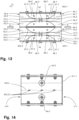
- Figure 18 shows a cross-sectional view of a further passively operating mechanical functional unit 50 according to the invention for a shock wave protection valve with stop ribs 59 in the storage space 55.
- the sectional plane of the Fig. 18 goes through one of the stop ribs 59.
- Figure 19 shows schematically a top view of the functional unit 50 looking in the blocking direction X. Figures 18 and 19 are described together below.
- the functional unit 50 is largely analogous to the functional unit 1 Fig. 1 formed and comprises a flow channel 52 extending in the flow direction S.
- a flow area 54 is present in the flow channel 52, through which a ventilation flow can flow and which is delimited by a valve flap 57 arranged in the flow direction in the flow channel 52 from a storage space 55 also arranged in the flow channel 52 is.
- stop elements 59 are arranged in the storage space 55, which are designed as stop ribs aligned in the flow direction S.
- the stop ribs 59 form stops for the valve flap 57, which in the open position O rests on stop edges 59.1 of the stop ribs 59 pointing towards the flow area 54.
- the valve flap 57 is spring-loaded in the direction of the storage space 55 in such a way that it is pressed against the stop edges 59.1 with a spring force.
- valve flap 57 is designed to be resiliently flexible, the preload can be achieved in that the valve flap 57 is designed to be angled towards the storage space 55 in a foot area 57.1 in the relaxed state. Ie in the absence of the stop ribs 59, the valve flap 57 would in this case, for example, protrude into the storage space 55 at an angle relative to the flow direction S, as in Fig. 18 indicated by dashed lines as position U. If the valve flap 57 is attached in an articulated manner, for example an additional spring element (not shown) or the spring element of the joint, which holds the valve flap 57 in the open position (O), can apply the preload.
- an additional spring element not shown
- the spring element of the joint which holds the valve flap 57 in the open position (O)
- the stop rib can extend in the common storage space and have stop edges on both sides in the height direction H, so that the two valve flaps rest on the same stop rib from both sides (not shown). If two functional units are connected to each other in series, such as in Fig. 8 shown, the stop ribs can extend as a continuous slat into both storage spaces of the two connected functional units (not shown).
- the passively operating mechanical functional unit according to the invention forms a versatile basic unit for a shock wave protection valve.
- essentially identical functional units can be arranged flow-wise in parallel and in series in a shock wave protection valve, so that a comparatively low flow resistance is achieved and yet the passage of a shock wave can be effectively blocked in one or both directions along a flow direction.
Landscapes
- Engineering & Computer Science (AREA)
- General Engineering & Computer Science (AREA)
- Mechanical Engineering (AREA)
- Health & Medical Sciences (AREA)
- Business, Economics & Management (AREA)
- Emergency Management (AREA)
- General Health & Medical Sciences (AREA)
- Public Health (AREA)
- Check Valves (AREA)
- Air-Flow Control Members (AREA)
Description
Die Erfindung betrifft eine passiv arbeitende mechanische Funktionseinheit für ein Stosswellenschutzventil, insbesondere für eine Lüftungsanlage, einen Strömungskanal mit einem Durchströmbereich, welcher in einer Strömungsrichtung von einem Lüftungsstrom durchströmbar ist und der in einem Störungsfall in einer Sperrrichtung infolge einer in Sperrrichtung propagierenden Stosswelle blocl<ierbar ist. Weiter umfasst die Funktionseinheit eine blattartige Ventilklappe, die in einer Offenstellung gehalten ist und die in einem Störungsfall durch die Stosswelle zumindest abschnittweise quer zur Strömungsrichtung in den Durchströmbereich in eine Schliessstellung auslenkbar ist, in welcher der Durchströmbereich in der Sperrrichtung von der Ventilklappe blockiert ist. Die Erfindung betrifft auch ein Stosswellenschutzventil umfasst eine derartige Funktionseinheit sowie eine Lüftungsanlage und eine Prüfanlage mit einem derartigen Stossventil. Weiter betrifft die Erfindung ein Verfahren zum Messen eines Schliessdrucks und/oder eines Strömungswiderstandes eines derartigen Stosswellenschutzventils sowie dessen Verwendung in einem Prüflabor.The invention relates to a passively operating mechanical functional unit for a shock wave protection valve, in particular for a ventilation system, a flow channel with a flow area through which a ventilation stream can flow in a flow direction and which can be blocked in a blocking direction in the event of a fault as a result of a shock wave propagating in the blocking direction . The functional unit further comprises a leaf-like valve flap which is held in an open position and which, in the event of a fault, can be deflected by the shock wave at least in sections transversely to the flow direction into the flow area into a closed position, in which the flow area is blocked in the blocking direction by the valve flap. The invention also relates to a shock wave protection valve comprising such a functional unit as well as a ventilation system and a testing system with such a shock valve. The invention further relates to a method for measuring a closing pressure and/or a flow resistance of such a shock wave protection valve and its use in a testing laboratory.
Stosswellenschutzventile werden vornehmlich in Bereichen eingesetzt, in denen eine Belüftung erforderlich ist, jedoch das Risiko besteht, dass Personen oder Anlagen infolge von Druckluftstössen Schaden nehmen können. Beispielsweise werden Stosswellenschutzventile als Drucl<wellensicherung für die Zu- und Abluftöffnungen von Lüftungskanälen von Schutzräumen für Personen oder Anlagen, Containments für Kernkraftwerke, Offshore-Anlagen oder militärischen Bauten eingesetzt. Stosswellenschutzventile bieten hierbei wirksamen Schutz gegen die Einwirkungen der Druckwellen von z.B. nuklearen oder konventionellen Detonationen und verhindern eine Propagation der Druckwelle in die Lüftungskanäle der Lüftungsanlage bzw. aus den Lüftungskanälen heraus.Shock wave protection valves are primarily used in areas where ventilation is required, but there is a risk that people or systems could be damaged as a result of compressed air surges. For example, shock wave protection valves are used as pressure wave protection for the supply and exhaust air openings of ventilation ducts of shelters for people or systems, containments for nuclear power plants, offshore systems or military buildings. Shock wave protection valves offer effective protection against the effects of pressure waves from, for example, nuclear or conventional detonations and prevent them Propagation of the pressure wave into the ventilation ducts of the ventilation system or out of the ventilation ducts.
Unterschieden wird zwischen aktiven und passiven Stosswellenschutzventilen: Aktive Stosswellenschutzventile benötigen für den drucksicheren Verschluss Fremdenergie und eine Steuerung. Sie registrieren mit Hilfe von Sensoren den von der eingehenden Stosswelle verursachten Druckanstieg und lösen in der Folge durch eine Aktuator den Verschluss des Ventils aus. Passive Stosswellenschutzventile hingegen sind ohne Fremdenergie und Steuerung funktionsfähig, reagieren einzig auf die Wirkung der Stosswelle und verhindern aufgrund ihrer baulichen Beschaffenheit eine Druckausbreitung innerhalb der Rohrleitungen sowie in angrenzende Anlagenteile.A distinction is made between active and passive shock wave protection valves: Active shock wave protection valves require external energy and a control system for pressure-safe closure. With the help of sensors, they register the increase in pressure caused by the incoming shock wave and then use an actuator to trigger the closure of the valve. Passive shock wave protection valves, on the other hand, function without external energy or control, react only to the effect of the shock wave and, due to their structural nature, prevent pressure from spreading within the pipelines and into adjacent parts of the system.
Ein derartiges passives Stosswellenschutzventil in einem Zuluft- bzw. Abluftkanal eines Boilers im militärischen Bereich ist z.B. aus der
Aufgabe der Erfindung ist es daher, eine dem eingangs genannten technischen Gebiet zugehörende passiv arbeitende mechanische Funktionseinheit für ein Stosswellenschutzventil sowie ein Stosswellenschutzventil zu schaffen, welche die Nachteile des Standes der Technik überwinden. Insbesondere ist es eine Aufgabe der Erfindung, eine kostengünstig herstellbare und konstruktiv einfache derartige Funktionseinheit für ein Stosswellenschutzventil sowie ein derartiges Stosswellenschutzventil, insbesondere für die Raumbelüftung, bereitzustellen, welche bei guten Sperreigenschaften einen vergleichsweise geringen Strömungswiderstand aufweisen. Weiter ist es eine Aufgabe der Erfindung, ein Verfahren zum Messen eines Schliessdrucks und/oder eines Strömungswiderstandes sowie eine Verwendung eines derartigen Stosswellenschutzventils bereitzustellen.The object of the invention is therefore to create a passively operating mechanical functional unit for a shock wave protection valve and a shock wave protection valve belonging to the technical field mentioned at the beginning, which Overcome disadvantages of the prior art. In particular, it is an object of the invention to provide a functional unit of this type for a shock wave protection valve and such a shock wave protection valve, in particular for room ventilation, which can be manufactured inexpensively and is structurally simple and which have a comparatively low flow resistance with good blocking properties. A further object of the invention is to provide a method for measuring a closing pressure and/or a flow resistance and a use of such a shock wave protection valve.
Die Lösung der Aufgabe ist durch die Merkmale der unabhängigen Ansprüche definiert. Gemäss der Erfindung umfasst eine passiv arbeitende mechanische Funktionseinheit für ein Stosswellenschutzventil, insbesondere für eine Lüftungsanlage, einen Strömungskanal mit einem Durchströmbereich, welcher in einer Strömungsrichtung von einem Lüftungsstrom durchströmbar ist und der in einem Störungsfall in einer Sperrrichtung infolge einer in Sperrrichtung propagierenden Stosswelle blocl<ierbar ist. Weiter umfasst die Funktionseinheit eine blattartige Ventilklappe, die in einer Offenstellung gehalten ist und die in einem Störungsfall durch die Stosswelle zumindest abschnittweise quer zur Strömungsrichtung in den Durchströmbereich in eine Schliessstellung auslenkbar ist, in welcher der Durchströmbereich in der Sperrrichtung von der Ventilklappe blockiert ist. Die Funktionseinheit zeichnet sich dadurch aus, dass die Ventilklappe in der Offenstellung im Wesentlichen in Strömungsrichtung ausgerichtet ist und zwischen einem im Strömungskanal angeordneten und entgegen der Sperrrichtung offenen Stauraum und dem Durchströmbereich derart angeordnet ist, dass im Störungsfall beim Durchgang der Stosswelle durch die Stosswelle im Stauraum ein Druck aufbaubar ist, welcher die Ventilklappe zumindest abschnittweise quer zur Strömungsrichtung drückt und in den Durchströmbereich auslenkt, sodass die Ventilklappe in die Schliessstellung gelangt.The solution to the problem is defined by the features of the independent claims. According to the invention, a passively operating mechanical functional unit for a shock wave protection valve, in particular for a ventilation system, comprises a flow channel with a flow area through which a ventilation flow can flow in a flow direction and which can be blocked in a blocking direction in the event of a fault as a result of a shock wave propagating in the blocking direction is. The functional unit further comprises a leaf-like valve flap which is held in an open position and which, in the event of a fault, can be deflected by the shock wave at least in sections transversely to the flow direction into the flow area into a closed position, in which the flow area is blocked by the valve flap in the blocking direction. The functional unit is characterized in that the valve flap is essentially aligned in the flow direction in the open position and is arranged between a storage space arranged in the flow channel and open against the blocking direction and the flow area in such a way that in the event of a malfunction when the shock wave passes through the shock wave in the storage space a pressure can be built up, which presses the valve flap at least in sections transversely to the direction of flow and deflects it into the flow area, so that the valve flap reaches the closed position.
Eine Dimension in Strömungsrichtung wird vorliegend als "Länge" bezeichnet während zwei senkrecht zur Strömungsrichtung und senkrecht zueinander ausgerichtete Dimensionen als "Breite" und "Höhe" bezeichnet werden. Die Höhe bezeichnet dabei die Dimension in derjenigen Richtung, in welcher die Ventilklappe zwischen Stauraum und Durchströmbereich angeordnet ist.One dimension in the direction of flow is referred to here as "length", while two dimensions aligned perpendicular to the direction of flow and perpendicular to each other are referred to as "width" and "height". The height refers to the dimension in the direction in which the valve flap is arranged between the storage space and the flow area.
Der "Strömungskanal" bezeichnet einen sich in Strömungsrichtung erstreckenden Abschnitt der Funktionseinheit, welcher in Längsrichtung beidseitig sich im Wesentlichen über seinen gesamten endseitigen Querschnitt erstreckende Öffnungen aufweist. Der Querschnitt des Strömungskanals kann konstant sein oder sich in Strömungsrichtung verändern. Der Querschnitt kann grundsätzlich rund oder vieleckig, insbesondere rechteckig, sein. Im Betrieb kann der Strömungskanal durch die Öffnungen über seinen gesamten endseitigen Querschnitt von dem Lüftungsstrom angeströmt werden. In der Regel ist der Strömungskanal von einer Begrenzungswand oder mehreren Begrenzungswänden umschlossen und durch diese senkrecht zur Strömungsrichtung begrenzt.The “flow channel” refers to a section of the functional unit that extends in the direction of flow and extends essentially over its length in the longitudinal direction on both sides Has openings extending across the entire end cross section. The cross section of the flow channel can be constant or change in the direction of flow. The cross section can fundamentally be round or polygonal, in particular rectangular. During operation, the ventilation flow can flow through the openings over its entire end cross section. As a rule, the flow channel is enclosed by one or more boundary walls and is delimited by them perpendicular to the direction of flow.
Der "Durchströmbereich" bezeichnet einen Bereich des Strömungskanals, durch welchen der Lüftungsstrom weitgehend ungehindert in der Strömungsrichtung strömen kann, wenn kein Störungsfall vorliegt. Der Durchströmbereich bildet einen Teilbereich des Strömungskanals und weist einen effektiven Querschnitt auf, welcher in Strömungsrichtung über die gesamte Länge des Strömungskanals für den Lüftungsstrom durchgängig ist, wenn kein Störungsfall vorliegt. Ein Störungsfall liegt vor, wenn z.B. infolge einer Detonation oder einer Deflagration eine Druck- oder Stosswelle im Lüftungsstrom eingeht, für deren Sperrung die Funktionseinheit vorgesehen und ausgebildet ist. Liegt im Betrieb kein Störungsfall vor, wird diese vorliegend als Normalbetrieb bezeichnet.The “flow area” refers to an area of the flow channel through which the ventilation flow can flow largely unhindered in the direction of flow if there is no malfunction. The flow area forms a partial area of the flow channel and has an effective cross section which is continuous in the flow direction over the entire length of the flow channel for the ventilation flow if there is no malfunction. A malfunction occurs when, for example, as a result of a detonation or deflagration, a pressure or shock wave occurs in the ventilation flow, which the functional unit is designed and designed to block. If there is no malfunction during operation, this is referred to as normal operation.
"blattartig" bezeichnet vorliegend eine Ausbildung der Ventilklappe als Platte mit zwei Hauptflächen, welche von umlaufenden, relativ dünnen Kante begrenzt sind. Die Ventilklappe kann z.B. aus einem Blech wie z.B. einem Edelstahlblech gefertigt sein. Die Ventilklappe ist zumindest abschnittweise quer zur Strömungsrichtung in den Durchströmbereich auslenkbar. Die Ventilklappe kann hierfür beispielsweise starr ausgebildet und um eine Schwenkachse schwenkbar sein oder sie kann biegsam ausgebildet sein und durch Biegung zumindest abschnittweise in den Durchströmbereich ausgelenkt werden.In the present case, “leaf-like” refers to a design of the valve flap as a plate with two main surfaces, which are delimited by circumferential, relatively thin edges. The valve flap can be made, for example, from a sheet metal such as a stainless steel sheet. The valve flap can be deflected at least in sections transversely to the flow direction into the flow area. For this purpose, the valve flap can, for example, be designed to be rigid and pivotable about a pivot axis, or it can be designed to be flexible and deflected at least in sections into the flow area by bending.
Die "Offenstellung" bezeichnet eine Stellung der Ventilklappe, in welcher sie im Normalzustand, insbesondere im Normalbetrieb angeordnet ist. In der Offenstellung ist die Ventilklappe im Wesentlichen in Strömungsrichtung ausgerichtet, d.h. die Hauptflächen der Ventilklappe sind im Wesentlichen parallel zur Strömungsrichtung angeordnet. Im Wesentlichen parallel kann vorliegend geringfügige Abweichungen aus einer parallelen Stellung umfassen, welche bis zu 15° betragen können. Der effektive Querschnitt des Durchströmbereichs somit von der Ventilklappe nicht oder nur unwesentlich verringert oder versperrt, wenn sich diese in der Offenstellung befindet.The “open position” refers to a position of the valve flap in which it is arranged in the normal state, in particular in normal operation. In the open position, the valve flap is essentially aligned in the flow direction, ie the main surfaces of the valve flap are arranged essentially parallel to the flow direction. In the present case, essentially parallel can include minor deviations from a parallel position, which can amount to up to 15°. The effective cross section of the flow area is therefore not or only slightly reduced or blocked by the valve flap when it is in the open position.
Die "Schliessstellung" bezeichnet eine Stellung der Ventilklappe, in welcher der Durchströmbereich von der Ventilklappe im Wesentlichen vollständig verschlossen ist, sodass dieser zumindest in Sperrrichtung nicht mehr vom Lüftungsstrom durchströmbar ist. Es versteht sich, dass in der Schliessstellung keine hermetische Abdichtung erfolgen muss. Wesentlich ist, dass in der Schliessstellung der Durchströmbereich für den Durchgang einer ausreichend starken Druckwelle im Lüftungsstrom, insbesondere einer Stosswelle blockiert ist.The “closed position” refers to a position of the valve flap in which the flow area of the valve flap is essentially completely closed, so that the ventilation flow can no longer flow through it, at least in the blocking direction. It goes without saying that there is no need for a hermetic seal in the closed position. It is important that in the closed position the flow area is blocked for the passage of a sufficiently strong pressure wave in the ventilation flow, in particular a shock wave.
Die "Sperrrichtung" bezeichnet diejenige Richtung, in welcher die Funktionseinheit den Durchgang einer Stosswelle blockieren kann. Die Sperrrichtung kann dabei der Strömungsrichtung gleichgerichtet oder entgegengerichtet sein, je nachdem ob die Funktionseinheit zur Anwendung im Sinne eines Druckventils respektive im Sinne eines Rückschlagventils vorgesehen ist.The “blocking direction” refers to the direction in which the functional unit can block the passage of a shock wave. The blocking direction can be directed in the same direction or in the opposite direction to the flow direction, depending on whether the functional unit is intended for use in the sense of a pressure valve or in the sense of a check valve.
Erfindungsgemäss ist im Strömungskanal neben der Ventilklappe der Stauraum derart ausgebildet, dass die Ventilklappe zwischen Durchströmbereich und Stauraum angeordnet ist. Der Stauraum definiert ein Stauvolumen im Strömungskanal und überdeckt einen Teilbereich des vom Lüftungsstrom angeströmten Querschnitts des Strömungskanals. Entgegen der Sperrrichtung, d.h. entgegen derjenigen Richtung, in welcher eine zu blockierende Stosswelle propagiert, ist der Stauraum zumindest bereichsweise offen, sodass das vom Stauraum definierte Stauvolumen mit dem Lüftungsstrom kommuniziert. In Sperrrichtung sowie in Richtung quer zur Strömungsrichtung ist der Stauraum im Wesentlichen gegenüber dem restlichen Strömungskanal, insbesondere gegenüber dem Durchströmbereich, abgeschlossen und bildet somit einen nicht durchströmbaren Sacl<bereich im Strömungskanal. In Richtung der Breite kann der Stauraum z.B. von Begrenzungswänden, insbesondere z.B. eines Gehäuses eines Stosswellenschutzventils oder hierfür vorgesehenen, separaten Trennwänden abgeschlossen sein.According to the invention, the storage space is designed in the flow channel next to the valve flap in such a way that the valve flap is arranged between the flow area and the storage space. The storage space defines a storage volume in the flow channel and covers a portion of the cross section of the flow channel through which the ventilation flow flows. Opposite to the blocking direction, i.e. opposite to the direction in which a shock wave to be blocked propagates, the storage space is at least partially open, so that the storage volume defined by the storage space communicates with the ventilation flow. In the blocking direction and in the direction transverse to the flow direction, the storage space is essentially closed off from the rest of the flow channel, in particular from the flow area, and thus forms a non-flowable storage area in the flow channel. In the width direction, the storage space can be closed off, for example, by boundary walls, in particular, for example, a housing of a shock wave protection valve or separate partition walls provided for this purpose.
Aufgrund des dynamischen Drucks einer mit der in Sperrrichtung eingehenden Stosswelle assoziierten Anströmung wird im Stauraum, im Gegensatz zum durchgängigen Durchströmbereich, ein Staudruck aufgebaut. Damit wird eine Druckdifferenz zwischen dem Stauraum und dem Durchströmbereich, d.h. ein Überdruck im Stauraum, erwirkt, welcher auf die dazwischen angeordnete Ventilklappe wirkt. Die Ventilklappe ist dabei derart auslenkbar ausgebildet, dass der Überdruck einen gewissen Schwellwert übersteigen muss, damit die Ventilklappe aus der Offenstellung in die Schliessstellung ausgelenkt wird. Der Schwellwert für den Überdruck definiert einen Übergang vom Normalbetrieb zum Störungsfall.Due to the dynamic pressure of a flow associated with the shock wave arriving in the blocking direction, a dynamic pressure is built up in the storage space, in contrast to the continuous flow area. This creates a pressure difference between the storage space and the flow area, ie an overpressure in the storage space, which acts on the valve flap arranged between them. The valve flap is designed to be deflectable in such a way that the excess pressure must exceed a certain threshold value so that the valve flap is deflected from the open position into the closed position. The Threshold value for the overpressure defines a transition from normal operation to a fault.
Indem die Ventilklappe erfindungsgemäss zwischen dem Stauraum und dem Durchströmbereich angeordnet ist, kann der im Stauraum aufgebaute Überdruck direkt und grossflächig auf die Ventilklappe wirken. Bei vergleichsweise kleinem angeströmten Querschnitt des Stauraums kann somit eine vergleichsweise grosse Kraft auf die Ventilklappe ausgeübt werde. Auf diese Weise wird erreicht, dass bei geringem Strömungswiderstand die Ventilklappe im Störungsfall zuverlässig in den Durchströmbereich ausgelenkt wird und in die Schliessstellung gelangt.By arranging the valve flap between the storage space and the flow area according to the invention, the excess pressure built up in the storage space can act directly and over a large area on the valve flap. With a comparatively small flow cross-section of the storage space, a comparatively large force can be exerted on the valve flap. In this way it is achieved that, with low flow resistance, the valve flap is reliably deflected into the flow area in the event of a malfunction and reaches the closed position.
Zudem wird der Druck der in Sperrrichtung eingehenden Stosswelle durch den Stauraum in eine Kraft quer zur Strömungsrichtung auf die Ventilklappe umgewandelt. Damit braucht die Ventilklappe im Gegensatz zu bekannten einschlägigen Vorrichtungen in der Offenstellung zum Auslenken keine zur eingehenden Stosswelle hin gerichtete Angriffsfläche aufzuweisen, d.h. es ist z.B. kein Anstellwinkel bezüglich der Strömungsrichtung erforderlich. Entsprechend kann die Ventilklappe in der Offenstellung in Strömungsrichtung ausgerichtet angeordnet sein. Damit ragt die Ventilklappe in der Offenstellung nicht in den Durchströmbereich hinein und beeinträchtigt den effektiven Querschnitt des Durchströmbereichs zugunsten eines geringen Strömungswiderstands nicht. Ebenso ist die Ventilklappe erfindungsgemäss in der Offenstellung gehalten, d.h. ist derartig befestigt, dass in Abwesenheit von äusseren Kräften die Ventilklappe in der Offenstellung verbleibt, womit dem Lüftungsstrom beim Durchströmen keine Strömungsenergie zum Offenhalten entnommen wird bzw. werden muss.In addition, the pressure of the shock wave arriving in the blocking direction is converted by the storage space into a force transverse to the flow direction on the valve flap. In contrast to known relevant devices, the valve flap does not need to have an attack surface directed towards the incoming shock wave in the open position for deflection, i.e. no angle of attack with respect to the direction of flow is required. Accordingly, the valve flap can be arranged aligned in the flow direction in the open position. This means that the valve flap does not protrude into the flow area in the open position and does not impair the effective cross section of the flow area in favor of low flow resistance. Likewise, according to the invention, the valve flap is held in the open position, i.e. is fastened in such a way that in the absence of external forces, the valve flap remains in the open position, which means that no flow energy is or has to be taken from the ventilation flow as it flows through to keep it open.
Gesamthaft wird somit eine konstruktiv einfache Funktionseinheit für ein Stosswellenschutzventil bereitgestellt, welche eine zuverlässige Sperreigenschaft hat und einen vergleichsweise geringen Strömungswiderstand aufweist. Die Funktionseinheit gemäss der Erfindung kommt bevorzugt bei der Raumbelüftung zur Anwendung. Die Funktionseinheit eignet sich besonders für Niederdrucl<anwendungen, bei welchen ein Lüftungsstrom im Normalbetrieb einen Druck zum Beispiel in der Grössenordnung von etwa 200 Pa aufweist und im Störungsfall ein Druck zum Beispiel im Bereich ab etwa 300 Pa liegt. Ganz allgemein eignet sich die Erfindung besonders für Anwendungen, bei denen im Normalbetrieb der Druckverlust im Ventil maximal 600 Pa beträgt.Overall, a structurally simple functional unit is provided for a shock wave protection valve, which has a reliable blocking property and a comparatively low flow resistance. The functional unit according to the invention is preferably used for room ventilation. The functional unit is particularly suitable for low-pressure applications in which a ventilation flow in normal operation has a pressure, for example, of the order of around 200 Pa and in the event of a fault, a pressure, for example, in the range of around 300 Pa. In general, the invention is particularly suitable for applications in which the pressure loss in the valve is a maximum of 600 Pa during normal operation.
Nachfolgend werden besondere Ausführungsformen beschrieben. Die Merkmale sind somit optional.Special embodiments are described below. The features are therefore optional.
In einer bevorzugten Ausführungsform ist die Ventilklappe federnd in die Schliessstellung auslenkbar. Die Ventilklappe ist dabei bevorzugt derart federnd auslenkbar, dass eine Rückstellkraft auf die Ventilklappe ausgeübt wird, welche diese von einer ausgelenkten Stellung, insbesondere der Schliessstellung, in die Offenstellung zurücl<stellt. Auf diese Weise kann erreicht werden, dass die mechanische Funktionseinheit nach einem Übergang in den Störungsfall automatisch wieder in die Offenstellung zurückversetzt wird, sobald die Bedingungen für den Störungsfall nicht mehr erfüllt sind. Die federnd auslenkbare Ventilklappe kann erreicht werden, indem die Ventilklappe beispielsweise zumindest bereichsweise oder gesamthaft federelastisch biegsam ausgebildet ist. Ebenso kann die Ventilklappe starr ausgebildet sein und über ein federbeaufschlagtes Scharnier oder Gelenk auslenkbar sein. Selbstverständlich sind auch Kombinationen von federbeaufschlagten Gelenken und federelastisch ausgebildeten Ventilklappen denkbar.In a preferred embodiment, the valve flap can be deflected resiliently into the closed position. The valve flap is preferably resiliently deflectable in such a way that a restoring force is exerted on the valve flap, which returns it from a deflected position, in particular the closed position, to the open position. In this way, it can be achieved that the mechanical functional unit is automatically returned to the open position after a transition to the event of a malfunction as soon as the conditions for the event of a malfunction are no longer met. The resiliently deflectable valve flap can be achieved by making the valve flap resiliently flexible, for example at least in some areas or as a whole. Likewise, the valve flap can be designed to be rigid and can be deflected via a spring-loaded hinge or joint. Of course, combinations of spring-loaded joints and spring-elastic valve flaps are also conceivable.
Alternativ kann die Ventilklappe zumindest bereichsweise plastisch deformierbar ausgebildet sein, sodass die Ventilklappe im Zuge des Auslenkens bleibend verformt wird und nach einem Störungsfall in der Schliessstellung verbleibt. Derartige Funktionseinheiten erfordern nach einem Störungsfall allerdings Unterhaltsarbeiten bzw. einen Austausch der Ventilklappe.Alternatively, the valve flap can be designed to be plastically deformable at least in some areas, so that the valve flap is permanently deformed in the course of deflection and remains in the closed position after a fault. However, such functional units require maintenance work or replacement of the valve flap after a malfunction.
Bevorzugt ist die Ventilklappe mit einem in Sperrrichtung gerichteten Fussbereich im Strömungskanal befestigt ist und erstreckt sich vom Fussbereich entgegen der Sperrrichtung. Sobald die Ventilklappe im Störungsfall durch den Überdruck im Stauraum zumindest bereichsweise in den Durchströmbereich ausgelenkt wird, weist die Ventilklappe zumindest bereichsweise einen gewissen Anstellwinkel bezüglich der Strömungsrichtung auf und kann somit von einer mit der eingehenden Stosswelle assoziierten Anströmung erfasst werden. Aufgrund der damit verbundenen Umlenkung eines Anteils der Anströmung an der Ventilklappe wird eine zusätzliche Kraft auf die Ventilklappe erzeugt, welche den Übergang in die Schliessstellung unterstützt bzw. beschleunigt.The valve flap is preferably fastened in the flow channel with a foot area directed in the blocking direction and extends from the foot area counter to the blocking direction. As soon as the valve flap is deflected at least partially into the flow area in the event of a fault due to the excess pressure in the storage space, the valve flap has a certain angle of attack with respect to the flow direction, at least partially, and can therefore be detected by an inflow associated with the incoming shock wave. Due to the associated redirection of a portion of the flow at the valve flap, an additional force is generated on the valve flap, which supports or accelerates the transition to the closed position.
In einer bevorzugten Ausführungsform ist der Fussbereich der Ventilklappe fest im Strömungskanal befestigt und die Ventilklappe ist zumindest bereichsweise biegsam ausgebildet. Die Auslenkbarkeit der Ventilklappe wird in diesem Fall durch die Biegsamkeit erreicht. Dies hat den Vorteil, dass die Auslenkbarkeit der Ventilklappe keine beweglichen Teile erfordert, welche gewartet werden müssen und mit der Zeit z.B. aufgrund Verschmutzung oder Korrosion an Funktionalität einbüssen können. Wie erwähnt ist die Ventilklappe in einer bevorzugten Ausführungsform federelastisch biegsam ausgebildet, sodass sie nach einem Störungsfall automatisch in die Offenstellung zurückgestellt wird.In a preferred embodiment, the foot area of the valve flap is firmly fastened in the flow channel and the valve flap is designed to be flexible at least in some areas. In this case, the deflection of the valve flap is achieved through its flexibility. This has the advantage that the deflection of the valve flap does not require any moving parts that require maintenance and can lose functionality over time, for example due to contamination or corrosion. As mentioned, in a preferred embodiment, the valve flap is designed to be resiliently flexible, so that it is automatically returned to the open position after a malfunction.
Alternativ, und je nach Anforderung ebenfalls bevorzugt, kann der Fussbereich der Ventilklappe gelenkig im Strömungskanal befestigt sein. In diesem Fall kann die gesamte Ventilklappe um das Gelenkt ausgelenkt werden. Dies hat den Vorteil, dass die Ventilklappe starr ausgebildet sein kann und damit eine robuste Konstruktion möglich ist. Eine Befestigung über ein Gelenk schliesst jedoch nicht aus, dass die Ventilklappe zudem biegsam, insbesondere federelastisch biegsam sein kann. Wie erwähnt ist die Ventilklappe bevorzugt federnd gelenkig befestigt, d.h. das Gelenk ist federbeaufschlagt, um die Ventilklappe nach einem Störungsfall automatisch in die Offenstellung zurückzustellen.Alternatively, and also preferred depending on the requirements, the foot area of the valve flap can be attached in an articulated manner in the flow channel. In this case, the entire valve flap can be deflected around the joint. This has the advantage that the valve flap can be designed to be rigid and thus a robust construction is possible. However, attachment via a joint does not exclude the fact that the valve flap can also be flexible, in particular resiliently flexible. As mentioned, the valve flap is preferably attached in a resiliently articulated manner, i.e. the joint is spring-loaded in order to automatically return the valve flap to the open position after a malfunction.
Bevorzugt weist die Ventilklappe an einem entgegen der Sperrrichtung weisenden freien Ende eine Schliesskante auf, mit welcher sie in der Schliessstellung an einer Begrenzungswand des Durchströmbereichs anliegt. Die Begrenzungswand, an welcher die Ventilklappe in der Schliessstellung anliegt, liegt in der Regel bezüglich des Durchströmbereichs der Ventilklappe gegenüber, wenn sich diese in der Offenstellung befindet. Die Schliessl<annte bildet dabei eine definierte Anlagefläche der Ventilklappe zur Anlage an der Begrenzungswand. Die Schliesskante kann z.B. durch einen abgewinkelten Bereich am freien Ende der Ventilklappe ausgebildet sein, mit welchem die Ventilklappe in der geneigten Schliessstellung zur besseren Abdichtung flächig an der Begrenzungswand anliegt. Der abgewinkelte Bereich kann auch zu einer Versteifung des freien Endes der Ventilklappe beitragen.The valve flap preferably has a closing edge at a free end pointing counter to the blocking direction, with which it rests against a boundary wall of the flow area in the closed position. The boundary wall against which the valve flap rests in the closed position is generally opposite the valve flap in terms of the flow area when it is in the open position. The closing element forms a defined contact surface of the valve flap for contact with the boundary wall. The closing edge can, for example, be formed by an angled area at the free end of the valve flap, with which the valve flap lies flat against the boundary wall in the inclined closed position for better sealing. The angled area can also help stiffen the free end of the valve flap.
Anstelle der oder zusätzlich zu der Schliesskante an der Ventilklappe kann auch ein Sitz an der Begrenzungswand ausgebildet sein, in welchem die Schliesskante zur besseren Abdichtung in der Schliessstellung angeordnet ist.Instead of or in addition to the closing edge on the valve flap, a seat can also be formed on the boundary wall, in which the closing edge is arranged for better sealing in the closed position.
In einer bevorzugten Ausführungsform ist die Ventilklappe in der Offenstellung zum Stauraum hin federnd vorgespannt, wobei wenigstens ein Anschlagselement, insbesondere im Stauraum, ausgebildet ist, an welchem die Ventilklappe in der Offenstellung anliegt. In der Offenstellung wird die Ventilklappe somit von der federnden Vorspannung gegen das Anschlagelement gedrückt. Das Anschlagselement ist derart ausgebildet, dass die Ventilklappe in Strömungsrichtung ausgerichtet ist, wenn sie in der Offenstellung daran anliegt. Das Anschlagselement verhindert, dass die Ventilklappe aus der Offenstellung in den Stauraum ausgelenkt werden kann.In a preferred embodiment, the valve flap is resiliently biased towards the storage space in the open position, with at least one stop element being formed, in particular in the storage space, against which the valve flap rests in the open position. In the open position, the valve flap is thus pressed against the stop element by the resilient preload. The stop element is designed such that the valve flap is aligned in the direction of flow when it rests against it in the open position. The stop element prevents the valve flap from being deflected from the open position into the storage space.
Das Anschlagselement kann eine in Strömungsrichtung ausgerichtete Anschlagsrippe mit einer Anschlagskante umfassen, an welcher die Ventilklappe anliegt. Ebenso sind stiftartige oder blockartige Elemente denkbar, welche verhindern, dass die Ventilklappe in den Stauraum ausgelenkt werden kann. Das Anschlagselement kann z.B. an einer Begrenzungswand oder an einem Träger befestigt sein, an welchem die Ventilklappe befestigt ist (siehe unten).The stop element can comprise a stop rib aligned in the direction of flow with a stop edge against which the valve flap rests. Pin-like or block-like elements are also conceivable, which prevent the valve flap from being deflected into the storage space. The stop element can, for example, be attached to a boundary wall or to a support to which the valve flap is attached (see below).
Die federnde Vorspannung bewirkt, dass eine Federkraft auf die Ventilklappe zum Stauraum hin wirkt. Die Funktionseinheit kann ein zusätzliches Federelement umfassen oder, sofern vorhanden, kann dasselbe Federelement die Federbelastung zum Stauraum hin aufbringen, welches das federnde Auslenken der Ventilklappe in den Durchströmbereich ermöglicht. Ebenso kann im Falle einer federelastisch biegsamen Ventilklappe diese selbst derart ausgebildet sein, dass in der Offenstellung eine Federkraft zum Stauraum hin wirkt. Hierzu kann die Ventilklappe zum Beispiel derart zum Stauraum hin abgewinkelt ausgebildet sein, dass sie in entspanntem Zustand, das heisst falls das Anschlagselement nicht vorhanden wäre, zumindest abschnittweise in den Stauraum hinein ausgelenkt ist. Insbesondere kann die Ventilklappe hierzu am Fussbereich zum Stauraum hin abgewinkelt sein.The resilient preload causes a spring force to act on the valve flap towards the storage space. The functional unit can include an additional spring element or, if present, the same spring element can apply the spring load towards the storage space, which enables the valve flap to be deflected resiliently into the flow area. Likewise, in the case of a resiliently flexible valve flap, this itself can be designed in such a way that a spring force acts towards the storage space in the open position. For this purpose, the valve flap can, for example, be designed to be angled towards the storage space in such a way that in the relaxed state, that is to say if the stop element were not present, it is at least partially deflected into the storage space. In particular, the valve flap can be angled towards the storage space at the foot area.
Indem die Ventilklappe bei dieser besonderen Ausführungsform zum Stauraum hin federnd vorgespannt ist und in der Offenstellung an dem Anschlagselement anliegt, ist die Ventilklappe nicht vollständig frei und es kann verhindert werden, dass die Ventilklappe während des Normalbetriebs vom Lüftungsstrom in unerwünschte Schwingungen versetzt oder in den Stauraum ausgelenkt wird. Die Federbelastung kann dabei an die konkreten Bedingungen des Luftstroms angepasst sein.Because the valve flap in this particular embodiment is resiliently biased towards the storage space and rests against the stop element in the open position, the valve flap is not completely free and it can be prevented that the valve flap During normal operation, the ventilation flow causes undesirable oscillations or deflects it into the storage space. The spring load can be adapted to the specific conditions of the air flow.
Im Zuge eines Störungsfalls z.B. bei einer eingehenden Druck- oder Stosswelle können beträchtliche Kräfte auf die Ventilklappe wirken. Bevorzugt umfasst die mechanische Funktionseinheit daher wenigstens zwei in Strömungsrichtung ausgerichtete und im Durchströmbereich angeordnete Stützrippen, welche jeweils wenigstens eine Auflagekante für die Ventilklappe aufweisen und an welchen die Ventilklappe in der Schliessstellung anliegen kann. Die Auflagekanten sind dabei bevorzugt in Richtung der Breite nebeneinander in einem Abstand zueinander angeordnet und derart ausgebildet, dass sie die Ventilklappe in der Schliessstellung entgegen der Sperrrichtung unterstützen. Die Ventilklappe liegt dabei in der Schliessstellung bevorzugt mit einer ihrer Hauptflächen auf den Auflagekanten auf.In the event of a malfunction, for example an incoming pressure or shock wave, considerable forces can act on the valve flap. The mechanical functional unit therefore preferably comprises at least two support ribs aligned in the flow direction and arranged in the flow area, each of which has at least one support edge for the valve flap and against which the valve flap can rest in the closed position. The support edges are preferably arranged next to one another at a distance from one another in the width direction and are designed in such a way that they support the valve flap in the closed position against the blocking direction. In the closed position, the valve flap preferably rests with one of its main surfaces on the support edges.
Je nach Breite des Durchströmbereichs kann es dabei vorteilhaft sein, wenigstens 4 oder wenigstens 8 Stützrippen vorzusehen, um eine ausreichende Unterstützung der Ventilklappe über die gesamte Breite sicherzustellen. Bevorzugt weisen die Stützrippen dabei einen konstanten Abstand in Richtung der Breite auf. Weiter bevorzugt sind die Stützrippen paarweise über eine Befestigungsbrücl<e, insbesondere im Querschnitt U-förmig, miteinander verbunden ausgebildet, womit jeweils zwei Stützrippen über die eine Befestigungsbrücke im Strömungskanal montiert werden können. Zudem wird durch die paarweise verbundenen Stützrippen eine strukturelle Stabilität der Stützrippen erhöht. Benachbarte paarweise verbundene Stützrippenpaare können an den angrenzenden Stützrippen, z.B. mit einer stabilisierenden Zwischenlage, miteinander verschraubt sein, um die strukturelle Stabilität weiter zu erhöhen. Die über die Befestigungsbrücke verbundenen Stützrippenpaare können z.B. als ein Stanz-Biegeteil aus einem Blech, insbesondere einem Edelstahlblech gefertigt sein.Depending on the width of the flow area, it can be advantageous to provide at least 4 or at least 8 support ribs in order to ensure sufficient support of the valve flap over the entire width. The support ribs preferably have a constant distance in the width direction. More preferably, the support ribs are connected to one another in pairs via a fastening bridge, in particular U-shaped in cross section, whereby two support ribs can be mounted in the flow channel via the one fastening bridge. In addition, the supporting ribs connected in pairs increase the structural stability of the supporting ribs. Adjacent pairs of supporting ribs connected in pairs can be screwed together on the adjacent supporting ribs, for example with a stabilizing intermediate layer, in order to further increase the structural stability. The pairs of supporting ribs connected via the fastening bridge can be made, for example, as a stamped and bent part from a sheet of metal, in particular a stainless steel sheet.
Es versteht sich, dass insbesondere bei geringeren Baugrössen nur eine einzelne Stützrippe oder gar keine Stützrippe vorhanden zu sein braucht oder, im Falle besonders breiter Ventilklappen, mehr als 8 Stützrippen vorteilhaft sein können.It goes without saying that, particularly with smaller sizes, only a single support rib or no support rib at all need be present or, in the case of particularly wide valve flaps, more than 8 support ribs can be advantageous.
Es hat sich gezeigt, dass die Ventilklappe in der Schliessstellung mit Vorteil in Sperrrichtung gegenüber der Strömungsrichtung geneigt ist, um im Störungsfall die aufgrund einer eingehenden Stosswelle wirkenden Kräfte besonders gut aufnehmen zu können. Mit Vorteil sind die Auflagekanten der Stützrippen daher in Sperrrichtung ebenfalls gegenüber der Strömungsrichtung geneigt. Auf diese Weise können die Auflagekanten die in den Durchströmbereich ausgelenkte Ventilklappe optimal in der geneigten Schliessstellung unterstützen. Bevorzugt beträgt der Neigungswinkel der Auflagekanten dabei weniger als 45°, vorzugsweise weniger als 30°, womit die Ventilklappe in der Schliessstellung in einer besonders widerstandsfähigen Ausrichtung unterstützt wird. Bevorzugt verlaufen die Auflagekanten bis an eine Begrenzungswand des Durchströmbereichs heran, welche der Ventilklappe bezüglich des Durchströmbereichs gegenüberliegt, wenn sich die Ventilklappe in der Offenstellung befindet.It has been shown that in the closed position the valve flap is advantageously inclined in the blocking direction relative to the flow direction in order to be able to absorb the forces acting due to an incoming shock wave particularly well in the event of a malfunction. The support edges of the support ribs are therefore also advantageously inclined in the blocking direction relative to the flow direction. In this way, the support edges can optimally support the valve flap deflected into the flow area in the inclined closed position. The angle of inclination of the support edges is preferably less than 45°, preferably less than 30°, which supports the valve flap in a particularly resistant orientation in the closed position. The support edges preferably extend up to a boundary wall of the flow area, which is opposite the valve flap with respect to the flow area when the valve flap is in the open position.
Besonders bei biegsam ausgebildeten Ventilklappen ist es vorteilhaft, wenn die Auflagekanten mit stetig zunehmendem Neigungswinkel gegenüber der Strömungsrichtung gekrümmt verlaufen. Insbesondere eine biegsame Ventilklappe kann sich somit beim Übergang in die Schliessstellung vom Fussbereich bis zum freien Ende mit stromaufwärts zunehmender Neigung an die Auflagekanten anlegen. Aufgrund der Krümmung kann eine gleichmässige Anlage erreicht werden, ohne dass die biegsame Ventilklappe knickt. Insbesondere bei federelastisch ausgebildeten Ventilklappen kann somit verhindert werden, dass im Störungsfall ein Elastizitätsbereich überstiegen und die Ventilklappe plastisch deformiert wird.Particularly in the case of flexible valve flaps, it is advantageous if the support edges are curved with a constantly increasing angle of inclination relative to the direction of flow. In particular, a flexible valve flap can thus rest against the support edges during the transition to the closed position from the foot area to the free end with an increasing inclination upstream. Due to the curvature, an even contact can be achieved without the flexible valve flap buckling. Particularly in the case of spring-elastic valve flaps, it can be prevented that in the event of a fault an elasticity range is exceeded and the valve flap is plastically deformed.
Weiter bevorzugt ist eine Ausführungsform, bei welcher die Ventilklappe eine Länge in Strömungsrichtung aufweist, welche wenigstens doppelt so gross ist, wie eine Höhe des Durchströmbereichs. Die Höhe des Durchströmbereichs bezeichnet hierbei die grösste senkrechte Distanz zwischen der Ventilklappe in der Offenstellung und einer gegenüberliegenden Begrenzungswand des Durchströmbereichs. Mit der bezüglich der Höhe des Durchströmbereichs wenigstens doppelt so grossen Länge der Ventilklappe wird erreicht, dass eine verhältnismässig geringe Auslenkung erforderlich ist, um den Durchströmbereich vollständig zu verschliessen. Insbesondere ist bei biegungsfreier Auslenkung der Ventilklappe aus einer direkt an den Durchströmbereich angrenzenden Offenstellung aufgrund der doppelt so grossen Länge nur ein Neigungswinkel von etwa 30° gegenüber der Strömungsrichtung erforderlich, um den Durchströmbereich vollständig zu verschliessen. Zudem kann aufgrund der vergleichsweise grossen Länge der Ventilklappe bei gegebener Höhe des Durchströmbereichs eine Fläche der Ventilklappe, auf welche der im Stauraum aufbaubare Überdruck wirkt, für eine grosse Kraftwirkung verhältnismässig gross gestaltet werden.Further preferred is an embodiment in which the valve flap has a length in the flow direction which is at least twice as large as a height of the flow area. The height of the flow area refers to the greatest vertical distance between the valve flap in the open position and an opposite boundary wall of the flow area. With the length of the valve flap being at least twice as large as the height of the flow area, it is achieved that a relatively small deflection is required in order to completely close the flow area. In particular, when the valve flap is deflected without bending, it is from a direction directly adjacent to the flow area In the open position, due to the twice the length, only an angle of inclination of around 30° relative to the flow direction is required to completely close the flow area. In addition, due to the comparatively large length of the valve flap, for a given height of the flow area, an area of the valve flap on which the excess pressure that can be built up in the storage space acts can be made relatively large for a large force effect.
Damit der sich im Störungsfall im Stauraum aufbauende Druck auf einfache Weise und möglichst direkt auf die Ventilklappe wirkt, bildet die Ventilklappe in einer bevorzugten Ausführungsform, insbesondere in der Offenstellung, eine Begrenzungswand des Stauraums. Vorzugsweise bildet die Ventilklappe dabei eine dem Durchströmbereich zugewandte Begrenzungswand des Stauraums und vorzugsweise gleichzeitig eine dem Stauraum zugewandte Begrenzungswand des Durchströmbereichs. Auf diese Weise kann der im Stauraum aufbaubare Überdruck direkt auf eine der Hauptflächen der Ventilklappe wirken und somit eine direkte Kraft ausüben, welche die Ventilklappe in den Durchströmbereich drückt. Die weiteren Begrenzungswände des Stauraums können z.B. durch Begrenzungswände des Strömungskanals oder durch separate Wandelemente gebildet werden und sind bevorzugt starr und unveränderlich ausgebildet. Die Ventilklappe bildet in diesem Fall eine veränderliche Begrenzungswand des Stauraums, dessen Stauvolumen sich während des Auslenkens der Ventilklappe, d.h. beim Übergang von der Offenstellung in die Schliessstellung ändert.So that the pressure that builds up in the storage space in the event of a fault acts on the valve flap in a simple manner and as directly as possible, in a preferred embodiment, the valve flap forms a boundary wall of the storage space, especially in the open position. The valve flap preferably forms a boundary wall of the storage space facing the flow area and preferably at the same time a boundary wall of the flow area facing the storage space. In this way, the excess pressure that can be built up in the storage space can act directly on one of the main surfaces of the valve flap and thus exert a direct force that pushes the valve flap into the flow area. The further boundary walls of the storage space can be formed, for example, by boundary walls of the flow channel or by separate wall elements and are preferably designed to be rigid and unchangeable. In this case, the valve flap forms a variable boundary wall of the storage space, the storage volume of which changes during the deflection of the valve flap, i.e. during the transition from the open position to the closed position.
Um eine möglichst grosse Kraftwirkung auf die Ventilklappe zu entfalten, erstreckt sich der Stauraum gemäss einer bevorzugten Ausführungsform quer zur Strömungsrichtung im Wesentlichen über die gesamte Breite der Ventilklappe. Auf dieses Weise kann die aus dem sich im Stauraum aufbaubaren Überdruck resultierende Kraft über die gesamte Breite der Ventilklappe wirken. Aus denselben Gründen ist es auch von Vorteil, wenn sich der Stauraum in Strömungsrichtung im Wesentlichen über die gesamte Länge der Ventilklappe erstreckt. Auf diese Weise kann die auf die Ventilklappe wirkende Kraft maximiert werden. Es versteht sich jedoch, dass der Stauraum grundsätzlich auch weniger breit bzw. weniger lang als die Ventilklappe ausgebildet sein kann, falls z.B. der in einem Störungsfall zu erwartenden Druckanstieg zu einer übermässigen Kraftwirkung führen würde, wenn er auf die gesamte Hauptfläche der Ventilklappe wirken würde.In order to develop the greatest possible force on the valve flap, the storage space, according to a preferred embodiment, extends transversely to the flow direction essentially over the entire width of the valve flap. In this way, the force resulting from the excess pressure that can build up in the storage space can act across the entire width of the valve flap. For the same reasons, it is also advantageous if the storage space extends essentially over the entire length of the valve flap in the direction of flow. In this way, the force acting on the valve flap can be maximized. However, it goes without saying that the storage space can in principle also be designed to be less wide or less long than the valve flap, for example if that is to be expected in the event of a malfunction Increase in pressure would lead to excessive force if it were to act on the entire main surface of the valve flap.
In einer bevorzugten Ausführungsform erstreckt sich die Ventilklappe quer zur Strömungsrichtung im Wesentlichen über eine gesamte Breite des Durchströmbereichs. Auf diese Weise kann sichergestellt werden, dass der Durchströmbereich von der Ventilklappe vollständig verschlossen werden kann. Bevorzugt erstrecken sich die Ventilklappe und insbesondere auch der Durchströmbereich über die gesamte Breite des Strömungskanals. Auf diese Weise kann der Strömungskanal optimal ausgenutzt werden, was letztlich eine kompakte Baugrösse der Funktionseinheit ermöglicht.In a preferred embodiment, the valve flap extends transversely to the flow direction essentially over an entire width of the flow area. In this way it can be ensured that the flow area can be completely closed by the valve flap. The valve flap and in particular the flow area preferably extend over the entire width of the flow channel. In this way, the flow channel can be optimally utilized, which ultimately enables a compact size of the functional unit.
In einer bevorzugten Ausführungsform weist der Stauraum eine geringere Höhe auf, als der Durchströmbereich. Auf diese Weise kann bei einem gegebenen Querschnitt des Strömungskanals der effektive Querschnitt des Durchströmbereichs verhältnismässig gross sein, während der Stauraum nur einen geringen Anteil des Eingangsquerschnitts des Strömungskanals in Anspruch nimmt.In a preferred embodiment, the storage space has a lower height than the flow area. In this way, for a given cross section of the flow channel, the effective cross section of the flow area can be relatively large, while the storage space only takes up a small proportion of the inlet cross section of the flow channel.
In einer bevorzugten Ausführungsform der Funktionseinheit ist in einem vorgesehenen Betrieb die Strömungsrichtung der Sperrrichtung gleichgerichtet. In diesem Fall ist der Durchgang einer Druck- oder Stosswelle in Richtung des strömenden Luftstroms blockierbar, sodass die Funktionseinheit zur Anwendung im Sinne eines Druckventils geeignet ist.In a preferred embodiment of the functional unit, the flow direction is aligned with the blocking direction in an intended operation. In this case, the passage of a pressure or shock wave in the direction of the flowing air stream can be blocked, so that the functional unit is suitable for use as a pressure valve.
Alternativ und je nach Anwendung ebenso bevorzugt ist in einem vorgesehene Betrieb die Strömungsrichtung der Sperrrichtung entgegengerichtet. In diesem Fall ist der Durchgang einer Druck- oder Stosswelle entgegen der Richtung des strömenden Luftstroms blockierbar, sodass die Funktionseinheit zur Anwendung im Sinne eines Rückschlagventils geeignet ist.Alternatively, and depending on the application, the flow direction is opposite to the blocking direction in an intended operation. In this case, the passage of a pressure or shock wave can be blocked against the direction of the flowing air stream, so that the functional unit is suitable for use as a check valve.
Die Erfindung betrifft auch ein Stosswellenschutzventil für Lüftungsanlagen umfassend wenigstens eine mechanische Funktionseinheit, die als eingangs als Lösung der Aufgabe definiert ist und die weitere optionale Merkmale aufweisen kann.The invention also relates to a shock wave protection valve for ventilation systems comprising at least one mechanical functional unit, which is initially defined as a solution to the problem and which can have further optional features.
Im Stosswellenschutzventil ist die wenigstens eine Funktionseinheit bevorzugt in einem Gehäuse mit zwei Luftstromöffnungen angeordnet, welche durch den Strömungskanal der wenigstens einen Funktionseinheit verbunden sind. Das Gehäuse ist mit Vorteil als Kanaleinbaukomponente zum Einbau in einen Lüftungskanal eines Belüftungssystems vorgesehen. Das Stosswellenschutzventil kann dabei mit einer oder beiden Luftstromöffnungen an den Lüftungskanal angeschlossen oder in diesen eingesetzt werden, womit der Lüftungsstrom den Strömungskanal der wenigstens einen Funktionseinheit anströmen und den Durchströmbereich durchströmen kann. Zum Anschluss an den Lüftungskanal weist das Gehäuse im Bereich einer oder beider Luftstromöffnungen bevorzugt Befestigungsmittel wie z.B. Befestigungsflansche oder -laschen für Verschraubungen auf. Das Gehäuse kann dabei gemäss einschlägigen Normen ausgebildet sein, um in bestehende normierte Belüftungssysteme integriert werden zu können. Das Gehäuse kann zudem den Strömungskanal der wenigstens einen Funktionseinheit und gegebenenfalls auch deren Durchströmbereich zumindest teilweise begrenzen, was eine vereinfachte Konstruktion ermöglicht.In the shock wave protection valve, the at least one functional unit is preferably arranged in a housing with two air flow openings, which are connected by the flow channel of the at least one functional unit. The housing is advantageously intended as a duct installation component for installation in a ventilation duct of a ventilation system. The shock wave protection valve can be connected to the ventilation duct with one or both air flow openings or inserted into it, so that the ventilation flow can flow into the flow duct of the at least one functional unit and flow through the flow area. For connection to the ventilation duct, the housing preferably has fastening means such as fastening flanges or tabs for screw connections in the area of one or both air flow openings. The housing can be designed in accordance with relevant standards in order to be able to be integrated into existing standardized ventilation systems. The housing can also at least partially limit the flow channel of the at least one functional unit and possibly also its flow area, which enables a simplified construction.
In einer bevorzugten Ausführungsform umfasst das Stosswellenschutzventil wenigstens eine weitere, gleichartige Funktionseinheit, welche parallel zur wenigstens einen Funktionseinheit angeordnet ist. Indem wenigstens eine weitere gleichartige Funktionseinheit parallel zur wenigstens einen Funktionseinheit im Stosswellenschutzventil angeordnet ist, kann ein in das Stosswellenschutzventil eintretender Lüftungsstrom beide Strömungskanäle der Funktionseinheiten anströmen. Auf diese Weise kann z.B. ein Strömungswiderstand des Stosswellenschutzventils verringert werden. Zudem können die Funktionseinheiten z.B. als Module ausgebildet sein, sodass das Stosswellenventil einfach skalierbar und an unterschiedliche Bedürfnisse anpassbar ist. Insbesondere können auch mehr als zwei gleichartige Funktionseinheiten in paralleler Anordnung vorgesehen sein.In a preferred embodiment, the shock wave protection valve comprises at least one further, similar functional unit, which is arranged parallel to the at least one functional unit. By arranging at least one further similar functional unit parallel to the at least one functional unit in the shock wave protection valve, a ventilation flow entering the shock wave protection valve can flow to both flow channels of the functional units. In this way, for example, a flow resistance of the shock wave protection valve can be reduced. In addition, the functional units can be designed as modules, for example, so that the shock wave valve is easily scalable and adaptable to different needs. In particular, more than two similar functional units can be provided in a parallel arrangement.
Bei zwei oder mehr parallel angeordneten Funktionseinheiten können auch konstruktive Synergien genutzt werden. Beispielsweise bilden in einer bevorzugten Ausführungsform des Stosswellenschutzventils die Stauräume der wenigstens einen und der wenigstens einen weiteren Funktionseinheit einen gemeinsamen Stauraum, welcher zwischen den Ventilklappen der wenigstens einen und der wenigstens einen weiteren Funktionseinheit angeordnet ist. Auf diese Weise kann eine kompakte Bauweise erreicht werden, da nur ein Stauraum erforderlich ist, um die Ventilklappen zweier Funktionseinheiten in die jeweiligen Durchströmbereiche auszulenken. Bevorzugt begrenzen die Ventilklappen den Stauraum quer zur Strömungsrichtung an zwei quer zur Strömungsrichtung gegenüberliegenden Seiten, sodass eine möglichst direkte Kraftwirkung aufgrund des im Stauraum aufbaubaren Überdrucks erreicht wird. Es versteht sich, dass auch mehr als zwei, insbesondere 4 oder 8, parallel angeordnete Funktionseinheiten im Stosswellenschutzventil vorgesehen sein können, welcher paarweise jeweils einen gemeinsamen Stauraum aufweisen. Auf dieses Weise kann die Baugrösse des Stosswellenventils kompakter gestaltet werden bzw. kann bei einer gegebenen Baugrösse ein möglichst grosser effektiver Querschnitt der zu Verfügung stehenden Durchströmbereiche bereitgestellt werden.With two or more functional units arranged in parallel, constructive synergies can also be used. For example, in a preferred embodiment of the shock wave protection valve, the storage spaces of the at least one and the at least one further functional unit form a common storage space which is arranged between the valve flaps of the at least one and the at least one further functional unit. In this way, a compact design can be achieved since only one storage space is required to deflect the valve flaps of two functional units into the respective flow areas. The valve flaps preferably delimit the storage space transversely to the flow direction on two opposite sides transversely to the flow direction, so that the most direct possible force effect is achieved due to the excess pressure that can be built up in the storage space. It goes without saying that more than two, in particular 4 or 8, functional units arranged in parallel can be provided in the shock wave protection valve, each of which has a common storage space in pairs. In this way, the size of the shock wave valve can be made more compact or, for a given size, the largest possible effective cross section of the available flow areas can be provided.
Weiter können bevorzugt die Ventilklappen der wenigstens einen und der wenigstens einen weiteren Funktionseinheit mit einem jeweiligen Fussbereich an einem gemeinsamen, insbesondere quer zur Strömungsrichtung zwischen den Funktionseinheiten angeordneten, Träger befestigt sein. Auf diese Weise kann Konstruktion des Stosswellenschutzventils weiter vereinfacht werden, indem Bauteile gemeinsam genutzt werden. Der gemeinsame Träger kann z.B. als Querbalken mit beispielsweise rechteckigem Querschnitt ausgebildet sein, welcher sich im Wesentlichen über die gesamte Breite durch das Gehäuse erstreckt.Furthermore, the valve flaps of the at least one and the at least one further functional unit can preferably be attached with a respective foot area to a common carrier, in particular arranged transversely to the flow direction between the functional units. In this way, construction of the shock wave protection valve can be further simplified by using components together. The common support can be designed, for example, as a crossbar with, for example, a rectangular cross-section, which extends through the housing essentially over the entire width.
Bevorzugt bildet der gemeinsame Träger dabei auch einen Abschluss des gemeinsamen Stauraums. Hierzu weist der gemeinsame Träger eine Höhe auf, welche im Wesentlichen der Höhe des Stauraums entspricht. Die Fussbereiche der beiden Ventilklappen können dabei beispielsweise an zwei in Richtung der Höhe gegenüberliegenden Seiten des Trägers befestigt sein, sodass der Stauraum von den Ventilklappen und dem Träger begrenzt wird.The common carrier preferably also forms a conclusion to the common storage space. For this purpose, the common carrier has a height which essentially corresponds to the height of the storage space. The foot areas of the two valve flaps can, for example, be attached to two sides of the carrier that are opposite in the height direction, so that the storage space is limited by the valve flaps and the carrier.
Mit Vorteil ist das Stosswellenschutzventil derart gestaltet, dass der Durchgang einer Druck- oder Stosswelle in beide Richtungen längs der Strömungsrichtung blocl<ierbar ist. Hierzu ist im Stosswellenschutzventil bevorzugt zu jeder der Funktionseinheiten eine weitere, bezüglich einer Ebene quer zur Strömungsrichtung spiegelsymmetrisch ausgebildete und in Serie angeschlossene weitere Funktionseinheit vorhanden. Dabei schliessen bevorzugt die Durchströmbereiche jedes Paares von seriell angeschlossenen Funktionseinheiten miteinander kommunizierend und vollständig überlappend aneinander an und bilden einen durchgehenden Durchströmbereich. Aufgrund der spiegelsymmetrischen Ausbildung der Funktionseinheiten sind die Sperrrichtungen der seriell angeschlossenen Funktionseinheiten einander entgegengesetzt. Die seriell angeschlossenen Funktionseinheiten werden im Betrieb jedoch in derselben vorgesehenen Strömungsrichtung vom Luftstrom durchströmt.The shock wave protection valve is advantageously designed in such a way that the passage of a pressure or shock wave can be blocked in both directions along the flow direction. For this purpose, each of the functional units is preferably provided with a further functional unit in the shock wave protection valve, which is designed to be mirror-symmetrical with respect to a plane transverse to the direction of flow and is connected in series. The flow areas of each pair of serially connected functional units preferably communicate with one another and completely overlap each other and form a continuous flow area. Due to the mirror-symmetrical design of the functional units, the blocking directions of the serially connected functional units are opposite to one another. During operation, however, the air flow flows through the serially connected functional units in the same intended flow direction.
Auch im Falle der seriell angeschlossenen Paare von Funktionseinheiten können konstruktiv Synergien genutzt werden. Beispielsweise weist jedes Paar von seriell aneinander angeschlossenen Funktionseinheiten bevorzugt wenigstens 2, insbesondere wenigstens 4, vorzugsweise wenigstens 8, gemeinsame, in Strömungsrichtung durchgehende Stützrippen auf, welche jeweils Auflagekanten für die Ventilklappen der Funktionseinheiten des Paares aufweisen. Auf diese Weise können die Stützrippen des Paares von Funktionseinheiten z.B. als durchgehende Leitflächen ausgebildet sein, was die Konstruktion vereinfacht. Die durchgehenden Stützrippen können wie oben erwähnt paarweise über eine Befestigungsbrücke, insbesondere U-förmig, miteinander verbunden ausgebildet sein, womit jeweils zwei durchgehende Stützrippen über die eine Befestigungsbrücke im Strömungskanal montiert werden können. Bevorzugt sind die Stützrippen dabei an dem oben erwähnten gemeinsamen Träger befestigt, an welchem auch die Ventilklappen der parallel angeordneten Funktionseinheiten befestigt sind. Die paarweise über die Befestigungsbrücke verbundenen, durchgehenden Stützrippen können auch in diesem Fall als ein Stanz-Biegeteil aus einem Blech, insbesondere einem Edelstahlblech gefertigt sein.Synergies can also be used constructively in the case of serially connected pairs of functional units. For example, each pair of functional units connected in series preferably has at least 2, in particular at least 4, preferably at least 8, common support ribs which are continuous in the direction of flow and which each have support edges for the valve flaps of the functional units of the pair. In this way, the support ribs of the pair of functional units can be designed, for example, as continuous guide surfaces, which simplifies the construction. As mentioned above, the continuous support ribs can be designed to be connected to one another in pairs via a fastening bridge, in particular in a U-shape, whereby two continuous support ribs can be mounted in the flow channel via the one fastening bridge. The support ribs are preferably attached to the above-mentioned common carrier, to which the valve flaps of the functional units arranged in parallel are also attached. In this case, too, the continuous support ribs connected in pairs via the fastening bridge can be made as a stamped and bent part from a sheet metal, in particular a stainless steel sheet.
In einer weiter bevorzugten Ausführungsform sind die Ventilklappen jedes Paares von seriell angeschlossenen Funktionseinheiten als gemeinsames, in Strömungsrichtung durchgehendes Blatt, insbesondere als ein durchgehendes Blech, vorzugsweise ein Edelstahlblech, ausgebildet. Die in diesem Fall biegsam, insbesondere federelastisch biegsam, ausgebildeten Ventilklappen können somit auf einfache Weise einstückig gefertigt werden. Ein in Längsrichtung zentraler Bereich des durchgehenden Blechs kann einen gemeinsamen Fussbereich der beiden Ventilklappen bilden, von welchem sich die Ventilklappen in entgegengesetzte Richtungen längs der Strömungsrichtung erstrecken. Bevorzugt ist der gemeinsame Fussbereich dabei an dem oben erwähnten gemeinsamen Träger befestigt, an welchem auch die Ventilklappen der parallel angeordneten Funktionseinheiten und/oder die durchgehenden Stützrippen befestigt sind.In a further preferred embodiment, the valve flaps of each pair of serially connected functional units are preferably a common sheet that is continuous in the direction of flow, in particular as a continuous sheet Stainless steel sheet, formed. The valve flaps, which in this case are designed to be flexible, in particular resiliently flexible, can thus be manufactured in one piece in a simple manner. A longitudinally central region of the continuous sheet metal can form a common foot region of the two valve flaps, from which the valve flaps extend in opposite directions along the flow direction. The common foot area is preferably attached to the above-mentioned common support, to which the valve flaps of the parallel functional units and/or the continuous support ribs are also attached.
Die Erfindung betrifft auch eine Lüftungsanlage mit wenigstens einem Lüftungskanal und wenigstens einem daran angeschlossenen Stosswellenventil wie vorliegend beschrieben. Die Lüftungsanlage kann dabei zur Raumlüftung z.B. in Wohn- oder Bürogebäuden oder als technische Lüftungsanlage z.B. als Rückkühlung, oder für Zuluft zu Dieselaggregaten, oder in Atoml<raftwerl<en, in Raffinerieanlagen oder auf Bohrinseln vorgesehen sein.The invention also relates to a ventilation system with at least one ventilation duct and at least one shock wave valve connected to it, as described here. The ventilation system can be intended for room ventilation, for example in residential or office buildings, or as a technical ventilation system, for example for recooling, or for supply air to diesel generators, or in nuclear power plants, in refinery plants or on oil rigs.
Die Erfindung betrifft auch eine Prüfanlage mit einem Stosswellengenerator und einem Stosswellenschutzventil wie vorliegend beschrieben. Die Prüfanlage kommt bevorzugt zur Anwendung, um einen Schliessdruck und/oder einen Strömungswiderstand des Stosswellenventils zu prüfen. Die Prüfanlage umfasst bevorzugt einen Lüftungskanal, über welchen das Stosswellenschutzventil an den Stosswellengenerator angeschlossen ist. Mit dem Stosswellengenerator ist eine Stosswelle erzeugbar, welche durch den Lüftungskanal propagiert und in Sperrrichtung in das Stosswellenventil eintritt. Die Prüfanlage kann auch einen Luftstromerzeuger aufweisen, welcher einen Luftstrom im Lüftungskanal erzeugt, der durch das Stosswellenventil strömt und einem vorgesehenen Normalbetrieb entspricht. Weiter weist die Prüfanlage bevorzugt einen oder mehrere Sensoren auf, mit welchen ein Druckabfall am Stosswellenschutzventil gemessen werden kann. Bevorzugt ist hierzu stromaufwärts und stromabwärts vom Stosswellenschutzventil jeweils wenigstens ein Drucksensor vorhanden. Mit einer bevorzugt vorhandenen Auswertungseinheit können von den Sensoren ermittelte Messwerte ausgewertet werden und beispielsweise mit vorgegebenen oder im Normalbetrieb ermittelten Werten verglichen werden, um festzustellen, ob das Stosswellenschutzventil im Störungsfall wie vorgesehen schliesst. Die Auswertungseinheit kann hierfür dazu ausgebildet sein, aus im Normalbetrieb ermittelten Messwerten einen Strömungswiderstand des Stosswellenschutzventils zu ermitteln und den ermittelten Strömungswiderstand als Vergleichswert für einen Strömungswiderstand im Störungsfall zu benutzen.The invention also relates to a testing system with a shock wave generator and a shock wave protection valve as described herein. The testing system is preferably used to check a closing pressure and/or a flow resistance of the shock wave valve. The testing system preferably includes a ventilation duct through which the shock wave protection valve is connected to the shock wave generator. The shock wave generator can be used to generate a shock wave, which propagates through the ventilation duct and enters the shock wave valve in the blocking direction. The testing system can also have an air flow generator, which generates an air flow in the ventilation duct, which flows through the shock wave valve and corresponds to an intended normal operation. Furthermore, the testing system preferably has one or more sensors with which a pressure drop at the shock wave protection valve can be measured. For this purpose, at least one pressure sensor is preferably present upstream and downstream of the shock wave protection valve. With a preferably present evaluation unit, measured values determined by the sensors can be evaluated and, for example, compared with predetermined values or values determined during normal operation in order to determine whether the shock wave protection valve closes as intended in the event of a malfunction. The evaluation unit can be designed for this purpose from those determined during normal operation Measured values to determine a flow resistance of the shock wave protection valve and to use the determined flow resistance as a comparison value for a flow resistance in the event of a malfunction.
Die Erfindung betrifft auch ein Verfahren zum Messen eines Schliessdrucks und/oder eines Strömungswiderstandes eines Stosswellenschutzventils wie vorliegend beschrieben. Das Verfahren umfasst die Schritte:
- a) Einsetzen des Stosswellenschutzventils in einen Stosswellenrohr;
- b) Erzeugen eines konstanten Luftstroms im Stosswellenrohr;
- c) Bestimmung eines Messwertes des Luftstroms;
- d) Erzeugen einer Stosswelle im Stosswellenrohr;
- e) Bestimmung eines Messwertes für den Druckabfall;
- f) Vergleichen der Messwerte mit vorgegebenen Werten um festzustellen, ob das Stosswellenschutzventil schliesst.
- a) Inserting the shock wave protection valve into a shock wave tube;
- b) generating a constant air flow in the shock wave tube;
- c) determining a measured value of the air flow;
- d) generating a shock wave in the shock wave tube;
- e) Determination of a measured value for the pressure drop;
- f) Comparing the measured values with specified values to determine whether the shock wave protection valve closes.
Bevorzugt wird das erfindungsgemässe Verfahren auf einer erfindungsgemässen Prüfanlage ausgeführt.The method according to the invention is preferably carried out on a testing system according to the invention.
Die Erfindung betrifft auch die Verwendung eines Stosswellenschutzventils wie vorliegend beschrieben in einem Prüflabor für Explosionsschutz-Bestimmungen. Die Verwendung in einem Prüflabor für Explosionsschutz-Bestimmungen kann die Verwendung einer erfindungsgemässen Prüfanlage wie vorliegend beschrieben umfassen.The invention also relates to the use of a shock wave protection valve as described herein in a testing laboratory for explosion protection regulations. The use in a testing laboratory for explosion protection regulations can include the use of a testing system according to the invention as described herein.
Aus der nachfolgenden Detailbeschreibung und der Gesamtheit der Patentansprüche ergeben sich weitere vorteilhafte Ausführungsformen und Merkmalskombinationen der Erfindung.Further advantageous embodiments and combinations of features of the invention result from the following detailed description and the entirety of the patent claims.
Die zur Erläuterung des Ausführungsbeispiels verwendeten Zeichnungen zeigen schematisch:
- Fig. 1
- eine Querschnittsansicht einer passiv arbeitenden mechanischen Funktionseinheit gemäss der Erfindung für ein Stosswellenschutzventil mit einer Ventilklappe in einer Offenstellung;
- Fig. 2
- eine Draufsicht auf die Funktionseinheit der
Fig. 1 mit Blickrichtung in einer Sperrrichtung X; - Fig. 3
- die Funktionseinheit der
Fig. 1 in einem Störungsfall, in welchem eine starr ausgebildete Ventilklappe in eine Schliessstellung ausgelenkt ist; - Fig. 4
- die Funktionseinheit der
Fig. 1 in einem Störungsfall, in welchem eine federelastisch biegsam ausgebildete Ventilklappe in eine Schliessstellung ausgelenkt ist; - Fig. 5
- eine erfindungsgemässe Funktionseinheit mit einer federelastisch biegsamen Ventilklappe in eine Offenstellung mit Stützrippen zur Stützung der Ventilklappe in einer Schliessstellung;
- Fig. 6
- eine Draufsicht in Sperrrichtung auf die Funktionseinheit der
Fig. 5 ; - Fig. 7
- ein Stosswellenschutzventil gemäss der Erfindung mit zwei gleichartigen Funktionseinheiten, welche parallel zueinander angeordnete sind;
- Fig. 8
- ein Stosswellenschutzventil gemäss der Erfindung, mit zwei gleichartigen Funktionseinheiten, welche seriell aneinander anschliessen;
- Fig. 9
- ein Stosswellenschutzventil gemäss der Erfindung mit vier gleichartigen Funktionseinheiten, welche paarweise seriell angeschlossen und parallel angeordnet sind;
- Fig. 10
- eine äussere Schrägansicht eines Stosswellenschutzventils gemäss der
Erfindung mit 8 Funktionseinheiten; - Fig. 11
- eine Draufsicht in einer Sperrrichtung auf das Stosswellenschutzventil der
Fig. 10 ; - Fig. 12
- einen Längsquerschnitt des Stosswellenschutzventils der
Fig. 10 in einer Ebene parallel zu einer Längsrichtung und zu einer Breitenrichtung; - Fig. 13
- einen Längsquerschnitt in einer Ebene parallel zu einer Längsrichtung und einer Höhenrichtung des Stosswellenschutzventils der
Fig. 10 ; - Fig. 14
- eine äussere Seitenansicht des Stosswellenschutzventils der
Fig. 10 ; - Fig. 15
- eine Anordnung von zwei über jeweils eine Befestigungsbrücke verbundenen Stützrippenpaaren mit geradlinigen Auflagekanten;
- Fig. 16
- eine Anordnung von zwei über jeweils eine Befestigungsbrücke verbundenen Stützrippenpaaren mit gekrümmten Auflagekanten;
- Fig. 17
- eine Anordnung von drei über jeweils eine Befestigungsbrücke verbundenen Stützrippenpaaren gemäss der
Fig. 16 ; - Fig. 18
- eine Querschnittsansicht einer passiv arbeitenden mechanischen Funktionseinheit gemäss der Erfindung für ein Stosswellenschutzventil mit einer Ventilklappe in einer Offenstellung;
- Fig. 19
- eine Draufsicht auf die Funktionseinheit der
Fig. 18 mit Blickrichtung in einer Sperrrichtung X.
- Fig. 1
- a cross-sectional view of a passively operating mechanical functional unit according to the invention for a shock wave protection valve with a valve flap in an open position;
- Fig. 2
- a top view of the functional unit
Fig. 1 looking in a blocking direction X; - Fig. 3
- the functional unit of the
Fig. 1 in the event of a fault in which a rigid valve flap is deflected into a closed position; - Fig. 4
- the functional unit of the
Fig. 1 in the event of a fault in which a spring-elastic, flexible valve flap is deflected into a closed position; - Fig. 5
- a functional unit according to the invention with a resiliently flexible valve flap in an open position with support ribs to support the valve flap in a closed position;
- Fig. 6
- a top view in the blocking direction of the functional unit
Fig. 5 ; - Fig. 7
- a shock wave protection valve according to the invention with two similar functional units which are arranged parallel to one another;
- Fig. 8
- a shock wave protection valve according to the invention, with two similar functional units which connect to one another in series;
- Fig. 9
- a shock wave protection valve according to the invention with four similar functional units, which are connected in series in pairs and arranged in parallel;
- Fig. 10
- an external oblique view of a shock wave protection valve according to the invention with 8 functional units;
- Fig. 11
- a top view in a blocking direction of the shock wave protection valve
Fig. 10 ; - Fig. 12
- a longitudinal cross section of the shock wave protection valve
Fig. 10 in a plane parallel to a longitudinal direction and a width direction; - Fig. 13
- a longitudinal cross section in a plane parallel to a longitudinal direction and a height direction of the shock wave protection valve
Fig. 10 ; - Fig. 14
- an external side view of the shock wave protection valve
Fig. 10 ; - Fig. 15
- an arrangement of two pairs of support ribs with straight support edges, each connected via a fastening bridge;
- Fig. 16
- an arrangement of two pairs of support ribs with curved support edges, each connected via a fastening bridge;
- Fig. 17
- an arrangement of three pairs of support ribs each connected via a fastening bridge according to
Fig. 16 ; - Fig. 18
- a cross-sectional view of a passively operating mechanical functional unit according to the invention for a shock wave protection valve with a valve flap in an open position;
- Fig. 19
- a top view of the functional unit
Fig. 18 with a viewing direction in a blocking direction X.
Grundsätzlich sind in den Figuren gleiche Teile mit gleichen Bezugszeichen versehen.Basically, the same parts are given the same reference numbers in the figures.
Zwischen dem Durchströmbereich 4 und dem Stauraum 5 ist eine Ventilklappe 7 angeordnet, welche sich im Wesentlichen parallel zur Strömungsrichtung S erstreckt. Die Ventilklappe 7 ist mit einem Fussbereich 7.1 am Träger 6 befestigt und erstreckt sich entgegen der Sperrrichtung X. Die Ventilklappe 7 ist in einer Offenstellung O gehalten, wobei ihre Befestigung derart beschaffen ist, dass die Ventilklappe 7 in Abwesenheit von äusseren Kräften in der Offenstellung O verbleibt.A
Ein freies Ende 7.2 der Ventilklappe 7 ist bei der Eingangsöffnung 5.2 des Stauraums 5 angeordnet. Die Ventilklappe 7 begrenzt den Stauraum 5 zum Durchströmbereich 4 hin in einer Richtung quer zur Strömungsrichtung S, welche vorliegend als Höhenrichtung H bezeichnet wird und durch diejenige Richtung quer zur Strömungsrichtung S bzw. der Längsrichtung L definiert ist, in welcher der Durchströmbereich 4, die Ventilklappe 7 und der Stauraum 5 übereinander angeordnet sind. Der Durchströmbereich 4 ist in beide Richtungen von S frei durchströmbar.A free end 7.2 of the
Der Strömungskanal 2 weist eine Höhe h1 in Richtung von H auf. Der Stauraum 5 weist eine Höhe h3 auf, welche im Wesentlichen durch den Träger 6 vorgegeben ist. Der Träger 6 schliesst in einer Richtung entgegen der Richtung H mit der Ventilklappe 4 ab, d.h. er erstreckt sich nicht über die Ventilklappe 7 hinaus in den Durchströmbereich 4. Die Eingangsöffnung 5.2 des Stauraums 5 weist ebenfalls eine Höhe h3 auf. Der Durchströmbereich 4 weist eine Höhe h2 auf, welche deutlich grösser als die Höhe h3 des Stauraums 5 ist. Bevorzugt ist eine Länge l der Ventilklappe 7 in Längsrichtung L wenigstens doppelt so gross wie die Höhe h2 des Durchströmbereichs 4.The
Die Ventilklappe 7 erstreckt sich durch den gesamten Strömungskanal 2 in einer Richtung senkrecht zur Strömungsrichtung S, welche auch senkrecht auf H steht. Diese Richtung wird vorliegend als Breitenrichtung B bezeichnet. Die Ventilklappe 7 unterteilt somit den gesamten Strömungskanal 2 in den Durchströmbereich 4 und den Stauraum 5. Ein Querschnitt quer zur Strömungsrichtung S des Strömungskanals 2 ist somit im Wesentlichen vollständig von den Querschnitten des Durchströmbereichs 4 und Stauraums 5 überdeckt, abgesehen von der Stirnfläche des freien Endes 7.2 der Ventilklappe 7. In Breitenrichtung B ist der Stauraum 5 von den in Breitenrichtung B angeordneten Begrenzungswänden 3 begrenzt und abgeschlossen.The
In der Ausführungsform der
In der Schliessstellung C ist die Ventilklappe 7 um die quer zur Strömungsrichtung S, in Breitenrichtung B angeordnete Gelenkachse G in die Schliessstellung C ausgeschwenkt. Das freie Ende 7.2 der Ventilklappe 7 liegt an einer der Offenstellung O bezüglich des Durchströmbereichs 4 gegenüberliegenden Begrenzungswand 3.1 an. Die Ventilklappe 7 ist somit um einen im Wesentlichen konstanten Winkel α bezüglich der Strömungsrichtung S geneigt (vorbehaltlich einer allfälligen Durchbiegung aufgrund der Belastung). Indem die Länge I der Ventilklappe 7 bevorzugt wenigstens etwa doppelt so gross wie die Höhe h2 des Durchströmbereichs 4 ist, beträgt der Winkel α nicht mehr als etwa 30°.In the closed position C, the
Die Ventilklappe 7 verschliesst somit den Durchströmbereich 4 über seinen gesamten Querschnitt und bildet zusammen mit dem Abschluss 5.1 des Stauraums 5 einen vollständigen Verschluss des Strömungskanals 2. Ein Durchgang der Stosswelle in Sperrrichtung X durch die Funktionseinheit 1 ist somit blockiert.The
Die Auslenkung der Ventilklappe 7 aus der Offenstellung O erfolgt aufgrund eines sich infolge der eingehenden Stosswelle aufbauenden Überdrucks P im Stauraum 5. Der Überdruck P ergibt sich aus einer mit der eingehenden Stosswelle assoziierten Anströmung der Eintrittsöffnung 5.2 des Stauraums 5. Durch den dynamischen Druck der Anströmung kann sich aufgrund des Abschlusses 5.1 in Sperrrichtung X im seitlich von den Begrenzungswänden 3 abgeschlossenen Stauraum 5 ein Staudruck aufbauen. Im Durchströmbereich 4 wird aufgrund derselben Anströmung hingegen kein Staudruck aufgebaut, da dieser frei durchgängig ist. Die sich ergebende Druckdifferenz zwischen Durchströmbereich 4 und Stauraum 5 ergibt den Überdruck P. Dieser Überdruck P wirkt auf eine dem Stauraum 5 zugewandte Fläche der Ventilklappe 7 und bewirkt somit eine Kraftwirkung FP in einer Richtung senkrecht zur Fläche der Ventilklappe 7. Die Kraftwirkung FP lenkt die Ventilklappe 7 in den Durchströmbereich 4 aus und drückt diese aus der Offenstellung O in die Schliessstellung C. Mit zunehmender Auslenkung bietet die Ventilklappe 7 zudem eine Angriffsfläche für den Anprall der mit der Stosswelle assoziierten Anströmung, was eine zusätzliche, die Auslenkung unterstützende Kraft auf die Ventilklappe 7 bewirkt.The deflection of the
Die in
Aufgrund des in Zusammenhang mit
Zur Unterstützung der Ventilklappe 7 in der Schliessstellung C sind in der Ausführungsform der
Die Ventilklappen 17 und 17' der Funktionseinheiten 10 und 10' sind mit Fussbereichen 17.1 und 17.1' in Höhenrichtung H quer zur Strömungsrichtung S, beidseitig bezüglich der Längsebene F, spiegelsymmetrisch am Träger 16 befestigt. In ihren Offenstellungen O erstrecken sich die Ventilklappen 17 und 17' in Strömungsrichtung S, weitgehend parallel zueinander, in Richtung entgegen der Sperrrichtung X. Zwischen den Ventilklappen 17 und 17' und den das Gehäuse 103 in Höhenrichtung H nach aussen begrenzenden Begrenzungswänden 103.1 und 103.1' sind Durchströmbereiche 14 und 14' der Funktionseinheiten 10 und 10' angeordnet. Lamellenartige Stützrippen 18 und 18' sind in Strömungsrichtung S ausgerichtet in den Durchströmbereichen 14 und 14' angeordnet. Ausgehend von den Fussbereichen 17.1 und 17.1' der Ventilklappen 17 und 17' weisen die Stützrippen 18 und 18' Auflagekanten 18.1 und 18.1' auf, welche sich entgegen der Sperrrichtung X zu Begrenzungswänden 103.1 und 103.1' des Gehäuses 103 hin gekrümmt erstrecken.The valve flaps 17 and 17 'of the
Ein Bereich, welcher von den Ventilklappen 17 und 17' in Höhenrichtung H und von dem Träger 16 in Sperrrichtung X begrenzt ist, bildet einen Stauraum 15, welcher entgegen der Sperrrichtung X eine in Höhenrichtung H von freien Längsenden 17.2 und 17.2' der Ventilklappen 17 und 17' begrenzte Eingangsöffnung 15.2 aufweist. Der Träger 16 bildet eine Abschluss 15.1 des Bereichs zwischen den Ventilklappen 17 und 17`.An area which is delimited by the valve flaps 17 and 17 'in the height direction H and by the
Der Stauraum 15 bildet damit einen gemeinsamen Stauraum 15 der beiden Funktionseinheiten 10 und 10`. Aufgrund der bezüglich der Längsebene F spiegelsymmetrischen Anordnung der beiden Funktionseinheiten 10 und 10' können strukturelle Synergien genutzt werden, um gesamthaft die Baugrösse des Stosswellenventils 100 kompakter zu gestalten bzw. bei gegebener Baugrösse einen möglichst grossen effektiven Querschnitt der Durchströmbereiche 14 und 14' bereitstellen zu können. Es versteht sich, dass sich die Ventilklappen 17 und 17' sowie die Durchströmbereiche 14 und 14' in Breitenrichtung B im Wesentlichen über die gesamte Breite zwischen den nicht dargestellten Seitenwänden des Gehäuses 103 erstrecken, d.h. auch im Wesentlichen über die gesamte Breite des Trägers 16. In Breitentenrichtung B ist der Stauraum 15 somit von den nicht dargestellten Seitenwänden begrenzt und abgeschlossen.The
Das Gehäuse 203 weist in Strömungsrichtung S an jedem Längsende eine Luftstromöffnung 210 und 211 auf. Die Luftstromöffnungen 211 und 210 schliessen jeweils an ein Strömungsende von Strömungskanälen 22 respektive 22' der Funktionseinheiten 20 und 20' an. Die Strömungskanäle 22 und 22' schliessen im Gehäuse 203 mit ihrem jeweils weiteren Strömungsende aneinander an. Ein ball<enartiger Träger 26 erstreckt sich zwischen zwei gegenüberliegenden Seitenwänden (nicht dargestellt) des Gehäuses 203 an eine Begrenzungswand 203.2 des Gehäuses 203 angrenzend in Richtung der Breite B des Stosswellenschutzventils 200. Der Träger 26 ist in Längsrichtung L mittig im Gehäuse 203, in Richtung von L zwischen den Funktionseinheiten 20 und 20' angeordnet. Der Träger 26 ist mit seinen Längsenden an den nicht dargestellten Seitenwänden befestigt. Sämtliche weitere Komponenten und deren Ausrichtungen der Funktionseinheiten 20 und 20' entsprechen im Wesentlichen den Komponenten der Funktionseinheit 1 der
Entsprechend sind Ventilklappen 27 und 27' der Funktionseinheiten 20 und 20' mit Fussbereichen 27.1 und 27.1' am Träger 26 befestigt. In Ihren Offenstellungen O erstrecken sich die Ventilklappen 27 und 27' in Strömungsrichtung S ausgerichtet von den Fussbereichen 27.1 und 27.1' in entgegengesetzte Richtungen und begrenzen in Richtung von H jeweils einen Stauraum 25 und 25`. Die Stauräume 25 und 25' sind jeweils in Richtung von X1 bzw. X2 durch den Träger 26 in Strömungsrichtung S abgeschlossen. Die Ventilklappe 27 der Funktionseinheit 20 erstreckt sich entgegen der Sperrrichtung X1 und die Ventilklappe 27' entgegen der Sperrrichtung X2. Die Ventilklappen 27 und 27' sind als in Längsrichtung L durchgehendes Blatt, insbesondere als durchgehendes Blech ausgebildet. Eine Länge l' des durchgehenden Blattes entspricht dabei im Wesentlichen einer Länge des Gehäuses 203. Die Ventilklappen 27 und 27' weisen somit einen gemeinsamen Fussbereich 27.1/27.1' auf, mit welchem sie am Träger 26 befestigt sind.Accordingly, valve flaps 27 and 27' of the
Zwischen der jeweiligen Ventilklappe 27 und 27' und einer der Begrenzungswand 203.2 in Höhenrichtung H gegenüberliegenden Begrenzungswand 203.1 des Gehäuses 203 sind Durchströmbereiche 24 und 24' der Funktionseinheiten 20 und 20' angeordnet. Die Durchströmbereiche 24 und 24' bilden einen durchgehenden Durchströmbereich, welcher die Luftstromöffnungen 210 und 211 von einem Lüftungsstrom längs der Strömungsrichtung S durchströmbar verbindet.
Lamellenartige Stützrippen 28 und 28' sind in Strömungsrichtung S ausgerichtet in den Durchströmbereichen 24 und 24' angeordnet. Ausgehend von den Fussbereichen 27.1 und 27.1' der Ventilklappen 27 und 27' weisen die Stützrippen 28 und 28' Auflagekanten 28.1 und 28.1' auf, welche sich in entgegengesetzte Richtungen längs der Längsrichtung L und jeweils entgegen der Sperrrichtung X1 bzw. X2 zu der Begrenzungswand 203.1 des Gehäuses 203 hin gekrümmt erstrecken. Die Stützrippen 28 und 28' sind als durchgehende Lamellen, insbesondere als durchgehende Bleche, ausgebildet, welche sich in beide Durchströmbereiche 24 und 24' erstrecken.Lamella-
Im Gehäuse 303 des Stosswellenschutzventils 300 erstreckt sich ein ball<enartiger Träger 36 zwischen zwei Seitenwänden (nicht dargestellt) des Gehäuses 303 in Richtung der Breite B des Stosswellenschutzventils 300. Der Träger ist bezüglich der Höhenrichtung H und der Längsrichtung L des Stosswellenschutzventils 300 jeweils mittig angeordnet. Der Träger 36 ist mit seinen Längsenden an den nicht dargestellten Seitenwänden des Gehäuses 303 befestigt. Die Ventilklappen 37' und 37" sowie 37 und 37‴ sind analog den Ventilklappen 27 und 27' der
Zwischen den durchgehenden Blättern der Ventilklappen 37, 37`, 37" und 37‴ sind somit zwei Stauräume 35 und 35' gebildet, welche in Längsrichtung jeweils in Sperrrichtung X, bzw. X2 vom Träger 36 abgeschlossen sind. Der Stauraum 35 bildet einen gemeinsamen Stauraum der Funktionseinheiten 30 und 30' während der Stauraum 35' einen gemeinsamen Stauraum der Funktionseinheiten 30" und 30‴ bildet. Die Stauräume 35 und 35' sind durch die nicht dargestellten Seitenwände des Gehäuses 303 in Richtung der Breite B abgeschlossen (analog der Darstellung in
Zwischen den durchgehenden Blättern der Ventilklappen 30 und 30‴ sowie 30' und 30" und jeweils gegenüberliegenden Begrenzungswänden 303.1 sind Durchströmbereiche 34, 34', 34" und 34‴ ausgebildet. Die Durchströmbereiche 34 und 34‴ sowie 34' und 34" sind paarweise durchgehend ausgebildet und schliessen seriell aneinander an. In den seriell aneinander angeschlossenen Durchströmbereichen 34 und 34‴ respektive 34' und 34" sind jeweils in Strömungsrichtung S ausgerichtete Stützrippen 38 und 38' respektive 38" und 38‴ mit Auflagekanten 38.1, 38.1', 38.1", 38.1‴ für die Ventilklappen 37, 37`, 37" und 37‴ in der Schliessstellung C ausgebildet. Die Stützrippen 38.1 und 28.1‴ sowie 38.1 ` und 38.1" von aneinander anschliessenden Durchströmbereichen sind jeweils als in Längsrichtung L durchgehende Lamellen ausgebildet.
Durch die serielle Anordnung der Funktionseinheiten 30' und 30" bzw. 30 und 30‴ wird ein Stosswellenschutzventil 300 bereitgestellt, welches in beide durchströmbaren Richtungen blockierbar ist und, aufgrund der parallelen Anordnung der Funktionseinheiten 30 und 30' bzw. 30" und 30‴ gleichzeitig einen verhältnismässig grossen durchströmbaren effektiven Querschnitt aufweist. Es versteht sich, dass die von den vier Funktionseinheiten 30, 30', 30" und 30‴ gebildete Einheit 39 in mehrfacher Ausfertigung in einem erfindungsgemässen Stosswellenventil strömungsmässig parallel zueinander angeordnet vorhanden sein kann (siehe z.B.
Im Stosswellenschutzventil 400 sind die beiden Einheiten 49 und 49' durch eine Trennwand 403.3 gegeneinander abgegrenzt, welche sich auf halber Höhe in Richtung von H über die gesamte Breite in Richtung von B parallel zur Strömungsrichtung S durch das Gehäuse 403 erstreckt. Seitenwände 403.4 begrenzen das Gehäuse 403 in der Richtung der Breite B nach aussen während die Wände 403.1 das Gehäuse 403 in Richtung von H nach aussen begrenzen.In the shock
Die Einheiten 49 und 49' sind in Richtung von H übereinander angeordnet und die Trennwand 403.3 bildet eine Begrenzungswand der innenliegenden Funktionseinheiten 40.2, 40.3 sowie 40.2' und 40.3`. Die beiden Einheiten 49 und 49' sind bezüglich einer von der Trennwand 403.3 definierten Ebene spiegelsymmetrisch ausgebildet.The
Ebenfalls an den Trägern 46 und 46' sind paarweise über Befestigungsbrücl<en 48.2 (siehe
Mit dem abgewinkelten Bereich liegen die Ventilklappen 47.1 bis 47.4 und 47.1` bis 47.4' in ihren Schliessstellungen C an den Wänden 403.1 bzw. der Trennwand 403.3 an. Zwischen den Paaren von Ventilklappen 47.1 und 47.2 sowie 47.3 und 47.4 und ebenso den Paaren der Ventilklappen 47.1' und 47.2' sowie 47.3' und 47.4' sind jeweils für jedes Paar gemeinsame Stauräume 45.1, 45.2, 45.3 respektive 45.4 angeordnetWith the angled area, the valve flaps 47.1 to 47.4 and 47.1' to 47.4' lie in their closed positions C on the walls 403.1 and the partition 403.3. Between the pairs of valve flaps 47.1 and 47.2 and 47.3 and 47.4 and also the pairs of valve flaps 47.1 'and 47.2' as well as 47.3' and 47.4', common storage spaces 45.1, 45.2, 45.3 and 45.4 are arranged for each pair
Die Funktionseinheit 50 ist weitgehend analog der Funktionseinheit 1 der
Zusätzlich gegenüber der Funktionseinheit 1 sind Anschlagselemente 59 im Stauraum 55 angeordnet, welche als in Strömungsrichtung S ausgerichtete Anschlagsrippen ausgebildet sind. Die Anschlagsrippen 59 bilden Anschläge für die Ventilklappe 57, welche in der Offenstellung O an zum Durchströmbereich 54 hin weisenden Anschlagskanten 59.1 der Anschlagsrippen 59 anliegt. Die Ventilklappe 57 ist dabei derart in Richtung zum Stauraum 55 federbelastet vorgespannt, dass sie mit einer Federkraft gegen die Anschlagkanten 59.1 gedrückt wird.In addition, opposite the
Ist die Ventilklappe 57 federelastisch biegsam ausgebildet, kann die Vorspannung dadurch erreicht werden, dass die Ventilklappe 57 in entspanntem Zustand zum Stauraum 55 hin in einem Fussbereich 57.1 abgewinkelt ausgebildet ist. D.h. in Abwesenheit der Anschlagsrippen 59 würde die Ventilklappe 57 in diesem Fall gegenüber der Strömungsrichtung S z.B. geneigt in den Stauraum 55 ragen, wie in
Sind zwei Funktionseinheiten parallel angeordnet und weisen einen gemeinsamen Stauraum auf wie z.B. in
Zusammenfassend ist festzustellen, dass die passiv arbeitende mechanische Funktionseinheit gemäss der Erfindung eine vielseitig einsetzbare Grundeinheit für ein Stosswellenschutzventil bildet. Insbesondere können im Wesentlichen baugleiche Funktionseinheiten strömungsmässig parallel und seriell in einem Stosswellenschutzventil angeordnet werden, sodass ein vergleichsweise geringer Strömungswiderstand erreicht wird und dennoch der Durchgang einer Stosswelle in einer oder beide Richtungen längs einer Strömungsrichtung wirkungsvoll blockierbar ist.In summary, it can be stated that the passively operating mechanical functional unit according to the invention forms a versatile basic unit for a shock wave protection valve. In particular, essentially identical functional units can be arranged flow-wise in parallel and in series in a shock wave protection valve, so that a comparatively low flow resistance is achieved and yet the passage of a shock wave can be effectively blocked in one or both directions along a flow direction.
Claims (15)
- A passively operating mechanical functional unit (1, 10, 10') for a shock wave protection valve (100, 200, 300), in particular for a ventilation system, comprising:a) a flow channel (2, 12, 12') with a through-flow region (4, 14, 14') through which a ventilation flow is able to flow in a direction of flow (S) and which, in the event of a disruption, is able to be blocked in a blocking direction as a result of a shock wave propagating in the blocking direction (X),b) a leaf-like valve flap (7, 17, 17') which is held in an open position (O) and which, in the event of a disruption, is able to be deflected by the shock wave, at least partially transversely to the direction of flow (S) into the through-flow region (4, 14, 14'), into a closed position (C) in which the through-flow region (4, 14, 14') is blocked in the blocking direction (X) by the valve flap (7, 17, 17'),
wherebyc) the valve flap (7, 17, 17') is arranged between a stagnation space (5, 15), arranged in the flow channel (2, 12, 12') and open counter to the blocking direction (X), and the through-flow region (4, 14, 14') such that,d) in the event of a disruption, as the shock wave passes through, a pressure (P) is able to be built up in the stagnation space (5, 15), which pressure pushes the valve flap (7, 17, 17') at least partially transversely to the direction of flow (S) and deflects it into the through-flow region (4, 14, 14') such that the valve flap (7, 17, 17') passes into the closed position (C),
characterized in thate) the valve flap (7, 17, 17') is oriented substantially in the direction of flow (S) in the open position (O). - The mechanical functional unit as claimed in claim 1, characterized in that the valve flap (7, 17, 17') is fastened in the flow channel (2, 12, 12') by a foot region (7.1, 17.1, 17.1') directed in the blocking direction (X), and extends from the foot region (7.1, 17.1, 17.1') counter to the blocking direction (X).
- The mechanical functional unit as claimed in claim 2, characterized in that the foot region (7.1, 17.1, 17.1') of the valve flap (7, 17, 17') is fastened fixedly in the flow channel (2, 12, 12') and the valve flap (7, 17, 17') is at least regionally flexible, in particular spring-elastically or in that the valve flap (7, 17, 17') is fastened in the flow channel (2, 12, 12'), in particular resiliently, in an articulated manner by the foot region (7.1, 17.1, 17.1').
- The mechanical functional unit as claimed in one of claims 1 to 3, characterized in that the valve flap (7, 17, 17') is resiliently preloaded, in the open position (0), toward the stagnation space (5, 15, 15'), wherein at least one stop element is formed, in particular in the stagnation space (5, 15, 15'), against which the valve flap (7, 17, 17') bears in the open position (O).
- The mechanical functional unit as claimed in claims 1 to 4, characterized in that at least two, in particular at least four, preferably at least eight, supporting ribs (8, 18, 18') that are oriented in the direction of flow (S) and are arranged in the through-flow region (4, 14, 14'), which supporting ribs (8, 18, 18') each have at least one contact edge (8.1, 18.1, 18.1') for the valve flap (7, 17, 17'), and against which the valve flap (7, 17, 17') bears in the closed position (C).
- The mechanical functional unit as claimed in claim 5, characterized in that the contact edges (8.1, 18.1, 18.1') of the supporting ribs (8, 18, 18') are each inclined, in the blocking direction (X), with respect to the direction of flow (S), and in particular an inclination angle (α) of the contact edges (8.1, 18.1, 18.1') with respect to the direction of flow (S) is less than 45°, preferably less than 30°.
- The mechanical functional unit as claimed in claim 6, characterized in that the contact edges (8.1, 18.1, 18.1') extend in a curved manner with a continuously increasing inclination angle (α) with respect to the direction of flow (S).
- The mechanical functional unit as claimed in one of claims 1 to 7, characterized in that the valve flap (7, 17, 17') has a length (l) in the direction of flow (S) which is at least twice as large as a height (h2) of the through-flow region (4, 14, 14').
- The mechanical functional unit as claimed in one of claims 1 to 8, characterized in that the valve flap (7, 17, 17') forms a boundary wall of the stagnation space (5, 15) and/or in that the stagnation space (5, 15) extends transversely to the direction of flow (S) substantially across an entire width of the valve flap (7, 17, 17') und/oder in that the stagnation space (5, 15) extends in the direction of flow (S) substantially along the entire length (l) of the valve flap (7, 17, 17').
- The mechanical functional unit as claimed in one of claims 1 to 9, characterized in that the valve flap (7, 17, 17') extends transversely to the direction of flow (S) substantially across an entire width of the through-flow region (4, 14, 14'), preferably across an entire width of the flow channel (2, 12, 12') and/or in that the stagnation space (5, 15, 15') has a smaller height than the through-flow region (4, 14, 14').
- A shock wave protection valve (100, 200, 300) for ventilation systems, comprising at least one mechanical functional unit (1, 10, 20) as claimed in one of claims 1 to 10, whereby, preferably, the at least one functional unit (1, 10, 20) is arranged in a housing (103, 203, 303) with two air-flow openings (110, 111, 210, 211, 310, 311) which are connected by the flow channel (2, 12, 22) of the functional unit (1, 10, 20), wherein in particular the housing (103, 203, 303) at least partially delimits the flow channel (2, 12, 22) of the at least one functional unit (1, 10, 20).
- A ventilation system having at least one ventilation channel and at least one shock wave valve (100, 200, 300, 400), connected thereto, as claimed in claim 11.
- A test system having a shock wave generator and a shock wave protection valve (100, 200, 300, 400) as claimed in claim 11.
- A method for measuring a closing pressure and/or a flow resistance of a shock wave protection valve (100, 200, 300, 400) as claimed in claim 11, comprising the steps ofa) inserting a shock wave protection valve (100, 200, 300, 400) into a shock wave tube;b) generating a constant air flow in the shock wave tube;c) determining a measured value of the air flow;d) generating a shock wave in the shock wave tube;e) determining a measured value for the pressure drop;f) comparing the measured values with predefined values in order to establish whether the shock wave protection valve closes.
- The use of a shock wave protection valve (100, 200, 300, 400) as claimed in claim 11 in a test laboratory for explosion protection regulations.
Applications Claiming Priority (2)
| Application Number | Priority Date | Filing Date | Title |
|---|---|---|---|
| CH00132/20A CH717113A8 (en) | 2020-02-05 | 2020-02-05 | Passive mechanical functional unit for a shock wave protection valve and shock wave protection valve. |
| PCT/EP2021/052316 WO2021156206A1 (en) | 2020-02-05 | 2021-02-01 | Passively operating mechanical functional unit for a shock wave protection valve, and shock wave protection valve |
Publications (3)
| Publication Number | Publication Date |
|---|---|
| EP4100673A1 EP4100673A1 (en) | 2022-12-14 |
| EP4100673B1 true EP4100673B1 (en) | 2024-01-31 |
| EP4100673C0 EP4100673C0 (en) | 2024-01-31 |
Family
ID=69779693
Family Applications (1)
| Application Number | Title | Priority Date | Filing Date |
|---|---|---|---|
| EP21703195.4A Active EP4100673B1 (en) | 2020-02-05 | 2021-02-01 | Passively operating mechanical functional unit for a shock wave protection valve, and shock wave protection valve |
Country Status (6)
| Country | Link |
|---|---|
| EP (1) | EP4100673B1 (en) |
| CN (1) | CN115053093B (en) |
| CA (1) | CA3165788A1 (en) |
| CH (1) | CH717113A8 (en) |
| SA (1) | SA522440048B1 (en) |
| WO (1) | WO2021156206A1 (en) |
Families Citing this family (2)
| Publication number | Priority date | Publication date | Assignee | Title |
|---|---|---|---|---|
| CN113944791B (en) * | 2021-11-23 | 2024-11-05 | 上海爵格工业工程有限公司 | Two-way explosion-proof valve |
| CN118862335B (en) * | 2024-06-24 | 2025-04-29 | 武汉理工大学 | Inter-board shock wave directional switch structure and design method thereof |
Family Cites Families (5)
| Publication number | Priority date | Publication date | Assignee | Title |
|---|---|---|---|---|
| US3139108A (en) * | 1962-09-24 | 1964-06-30 | Klingman Sanford | Pressure operated valve means |
| CN105333189B (en) * | 2015-11-24 | 2018-05-04 | 江苏爵格工业设备有限公司 | Shock wave resistance valve |
| DE202016004209U1 (en) * | 2016-04-06 | 2016-07-22 | Rexotec Ag | Pressure relief device for explosive decoupling of two system components |
| CN106195379B (en) * | 2016-09-13 | 2019-03-19 | 江苏省安全生产科学研究院 | The passive quick automatic cut-off valve of induced shockwaves |
| CN106885026B (en) * | 2017-03-17 | 2020-07-31 | 江苏爵格工业设备有限公司 | Normally closed one-way explosion-proof valve |
-
2020
- 2020-02-05 CH CH00132/20A patent/CH717113A8/en unknown
-
2021
- 2021-02-01 CA CA3165788A patent/CA3165788A1/en active Pending
- 2021-02-01 EP EP21703195.4A patent/EP4100673B1/en active Active
- 2021-02-01 WO PCT/EP2021/052316 patent/WO2021156206A1/en not_active Ceased
- 2021-02-01 CN CN202180012842.7A patent/CN115053093B/en active Active
-
2022
- 2022-08-04 SA SA522440048A patent/SA522440048B1/en unknown
Also Published As
| Publication number | Publication date |
|---|---|
| CA3165788A1 (en) | 2021-08-12 |
| CH717113A1 (en) | 2021-08-16 |
| SA522440048B1 (en) | 2024-08-29 |
| CN115053093A (en) | 2022-09-13 |
| EP4100673A1 (en) | 2022-12-14 |
| CH717113A8 (en) | 2022-01-31 |
| WO2021156206A1 (en) | 2021-08-12 |
| CN115053093B (en) | 2025-07-08 |
| EP4100673C0 (en) | 2024-01-31 |
Similar Documents
| Publication | Publication Date | Title |
|---|---|---|
| EP4100673B1 (en) | Passively operating mechanical functional unit for a shock wave protection valve, and shock wave protection valve | |
| EP2724071A1 (en) | Lamellar covering and spring element for a lamellar covering | |
| EP2870350B1 (en) | Check valve arrangement for internal combustion engine | |
| DE202004010819U1 (en) | Volume flow controller, in particular for air conditioning and ventilation systems | |
| EP0478100B1 (en) | Shut-off device for a gas duct | |
| DE102013112912A1 (en) | Support post for a wall or fence as well as wall or fence and wall-fence combination | |
| DE3716234C2 (en) | ||
| EP2655908B1 (en) | Guide carriage comprising a lubrication valve | |
| DE102013100310A1 (en) | Lock bar for a latch bar fitting | |
| EP4067594A1 (en) | Connection fitting | |
| EP2787265B1 (en) | Corner angle | |
| DE2810118A1 (en) | Stop and throttle valve - has plug bearing against end of resistance body containing through passages forming throttle channels | |
| EP1092899B1 (en) | Sealing device | |
| DE202019106957U1 (en) | Built-in wardrobe arrangement | |
| DE202014102436U1 (en) | Cover for a drainage channel | |
| DE2820208C2 (en) | Shut-off device, in particular pressure relief louvre | |
| DE19823310A1 (en) | Compound water meter | |
| EP2146156B1 (en) | Surge flap | |
| EP0616179B1 (en) | Closing device for an air passage | |
| EP1030986B1 (en) | Sealing device | |
| DE2236103C3 (en) | Air outlet for ventilation systems | |
| EP4230903B1 (en) | Device for fixing of pipes or conduits | |
| EP1130334B1 (en) | Volume flow regulator in particular for air conditioning systems | |
| DE102005020185B4 (en) | valve assembly | |
| AT519365B1 (en) | energy storage |
Legal Events
| Date | Code | Title | Description |
|---|---|---|---|
| STAA | Information on the status of an ep patent application or granted ep patent |
Free format text: STATUS: UNKNOWN |
|
| STAA | Information on the status of an ep patent application or granted ep patent |
Free format text: STATUS: THE INTERNATIONAL PUBLICATION HAS BEEN MADE |
|
| PUAI | Public reference made under article 153(3) epc to a published international application that has entered the european phase |
Free format text: ORIGINAL CODE: 0009012 |
|
| STAA | Information on the status of an ep patent application or granted ep patent |
Free format text: STATUS: REQUEST FOR EXAMINATION WAS MADE |
|
| 17P | Request for examination filed |
Effective date: 20220826 |
|
| AK | Designated contracting states |
Kind code of ref document: A1 Designated state(s): AL AT BE BG CH CY CZ DE DK EE ES FI FR GB GR HR HU IE IS IT LI LT LU LV MC MK MT NL NO PL PT RO RS SE SI SK SM TR |
|
| DAV | Request for validation of the european patent (deleted) | ||
| DAX | Request for extension of the european patent (deleted) | ||
| GRAP | Despatch of communication of intention to grant a patent |
Free format text: ORIGINAL CODE: EPIDOSNIGR1 |
|
| STAA | Information on the status of an ep patent application or granted ep patent |
Free format text: STATUS: GRANT OF PATENT IS INTENDED |
|
| INTG | Intention to grant announced |
Effective date: 20230925 |
|
| GRAS | Grant fee paid |
Free format text: ORIGINAL CODE: EPIDOSNIGR3 |
|
| GRAA | (expected) grant |
Free format text: ORIGINAL CODE: 0009210 |
|
| STAA | Information on the status of an ep patent application or granted ep patent |
Free format text: STATUS: THE PATENT HAS BEEN GRANTED |
|
| AK | Designated contracting states |
Kind code of ref document: B1 Designated state(s): AL AT BE BG CH CY CZ DE DK EE ES FI FR GB GR HR HU IE IS IT LI LT LU LV MC MK MT NL NO PL PT RO RS SE SI SK SM TR |
|
| REG | Reference to a national code |
Ref country code: GB Ref legal event code: FG4D Free format text: NOT ENGLISH Ref country code: CH Ref legal event code: EP |
|
| REG | Reference to a national code |
Ref country code: DE Ref legal event code: R096 Ref document number: 502021002579 Country of ref document: DE |
|
| REG | Reference to a national code |
Ref country code: IE Ref legal event code: FG4D Free format text: LANGUAGE OF EP DOCUMENT: GERMAN |
|
| U01 | Request for unitary effect filed |
Effective date: 20240209 |
|
| U07 | Unitary effect registered |
Designated state(s): AT BE BG DE DK EE FI FR IT LT LU LV MT NL PT SE SI Effective date: 20240220 |
|
| U20 | Renewal fee for the european patent with unitary effect paid |
Year of fee payment: 4 Effective date: 20240223 |
|
| PG25 | Lapsed in a contracting state [announced via postgrant information from national office to epo] |
Ref country code: GR Free format text: LAPSE BECAUSE OF FAILURE TO SUBMIT A TRANSLATION OF THE DESCRIPTION OR TO PAY THE FEE WITHIN THE PRESCRIBED TIME-LIMIT Effective date: 20240501 |
|
| PG25 | Lapsed in a contracting state [announced via postgrant information from national office to epo] |
Ref country code: RS Free format text: LAPSE BECAUSE OF FAILURE TO SUBMIT A TRANSLATION OF THE DESCRIPTION OR TO PAY THE FEE WITHIN THE PRESCRIBED TIME-LIMIT Effective date: 20240430 Ref country code: HR Free format text: LAPSE BECAUSE OF FAILURE TO SUBMIT A TRANSLATION OF THE DESCRIPTION OR TO PAY THE FEE WITHIN THE PRESCRIBED TIME-LIMIT Effective date: 20240131 |
|
| PG25 | Lapsed in a contracting state [announced via postgrant information from national office to epo] |
Ref country code: ES Free format text: LAPSE BECAUSE OF FAILURE TO SUBMIT A TRANSLATION OF THE DESCRIPTION OR TO PAY THE FEE WITHIN THE PRESCRIBED TIME-LIMIT Effective date: 20240131 |
|
| PG25 | Lapsed in a contracting state [announced via postgrant information from national office to epo] |
Ref country code: RS Free format text: LAPSE BECAUSE OF FAILURE TO SUBMIT A TRANSLATION OF THE DESCRIPTION OR TO PAY THE FEE WITHIN THE PRESCRIBED TIME-LIMIT Effective date: 20240430 Ref country code: HR Free format text: LAPSE BECAUSE OF FAILURE TO SUBMIT A TRANSLATION OF THE DESCRIPTION OR TO PAY THE FEE WITHIN THE PRESCRIBED TIME-LIMIT Effective date: 20240131 Ref country code: GR Free format text: LAPSE BECAUSE OF FAILURE TO SUBMIT A TRANSLATION OF THE DESCRIPTION OR TO PAY THE FEE WITHIN THE PRESCRIBED TIME-LIMIT Effective date: 20240501 Ref country code: ES Free format text: LAPSE BECAUSE OF FAILURE TO SUBMIT A TRANSLATION OF THE DESCRIPTION OR TO PAY THE FEE WITHIN THE PRESCRIBED TIME-LIMIT Effective date: 20240131 |
|
| PG25 | Lapsed in a contracting state [announced via postgrant information from national office to epo] |
Ref country code: PL Free format text: LAPSE BECAUSE OF FAILURE TO SUBMIT A TRANSLATION OF THE DESCRIPTION OR TO PAY THE FEE WITHIN THE PRESCRIBED TIME-LIMIT Effective date: 20240131 |
|
| PG25 | Lapsed in a contracting state [announced via postgrant information from national office to epo] |
Ref country code: PL Free format text: LAPSE BECAUSE OF FAILURE TO SUBMIT A TRANSLATION OF THE DESCRIPTION OR TO PAY THE FEE WITHIN THE PRESCRIBED TIME-LIMIT Effective date: 20240131 |
|
| PG25 | Lapsed in a contracting state [announced via postgrant information from national office to epo] |
Ref country code: SM Free format text: LAPSE BECAUSE OF FAILURE TO SUBMIT A TRANSLATION OF THE DESCRIPTION OR TO PAY THE FEE WITHIN THE PRESCRIBED TIME-LIMIT Effective date: 20240131 |
|
| PG25 | Lapsed in a contracting state [announced via postgrant information from national office to epo] |
Ref country code: CZ Free format text: LAPSE BECAUSE OF FAILURE TO SUBMIT A TRANSLATION OF THE DESCRIPTION OR TO PAY THE FEE WITHIN THE PRESCRIBED TIME-LIMIT Effective date: 20240131 |
|
| PG25 | Lapsed in a contracting state [announced via postgrant information from national office to epo] |
Ref country code: SK Free format text: LAPSE BECAUSE OF FAILURE TO SUBMIT A TRANSLATION OF THE DESCRIPTION OR TO PAY THE FEE WITHIN THE PRESCRIBED TIME-LIMIT Effective date: 20240131 |
|
| PG25 | Lapsed in a contracting state [announced via postgrant information from national office to epo] |
Ref country code: SM Free format text: LAPSE BECAUSE OF FAILURE TO SUBMIT A TRANSLATION OF THE DESCRIPTION OR TO PAY THE FEE WITHIN THE PRESCRIBED TIME-LIMIT Effective date: 20240131 Ref country code: SK Free format text: LAPSE BECAUSE OF FAILURE TO SUBMIT A TRANSLATION OF THE DESCRIPTION OR TO PAY THE FEE WITHIN THE PRESCRIBED TIME-LIMIT Effective date: 20240131 Ref country code: RO Free format text: LAPSE BECAUSE OF FAILURE TO SUBMIT A TRANSLATION OF THE DESCRIPTION OR TO PAY THE FEE WITHIN THE PRESCRIBED TIME-LIMIT Effective date: 20240131 Ref country code: CZ Free format text: LAPSE BECAUSE OF FAILURE TO SUBMIT A TRANSLATION OF THE DESCRIPTION OR TO PAY THE FEE WITHIN THE PRESCRIBED TIME-LIMIT Effective date: 20240131 |
|
| REG | Reference to a national code |
Ref country code: DE Ref legal event code: R097 Ref document number: 502021002579 Country of ref document: DE |
|
| PG25 | Lapsed in a contracting state [announced via postgrant information from national office to epo] |
Ref country code: MC Free format text: LAPSE BECAUSE OF FAILURE TO SUBMIT A TRANSLATION OF THE DESCRIPTION OR TO PAY THE FEE WITHIN THE PRESCRIBED TIME-LIMIT Effective date: 20240131 |
|
| PG25 | Lapsed in a contracting state [announced via postgrant information from national office to epo] |
Ref country code: MC Free format text: LAPSE BECAUSE OF FAILURE TO SUBMIT A TRANSLATION OF THE DESCRIPTION OR TO PAY THE FEE WITHIN THE PRESCRIBED TIME-LIMIT Effective date: 20240131 |
|
| PLBE | No opposition filed within time limit |
Free format text: ORIGINAL CODE: 0009261 |
|
| STAA | Information on the status of an ep patent application or granted ep patent |
Free format text: STATUS: NO OPPOSITION FILED WITHIN TIME LIMIT |
|
| 26N | No opposition filed |
Effective date: 20241101 |
|
| PG25 | Lapsed in a contracting state [announced via postgrant information from national office to epo] |
Ref country code: IE Free format text: LAPSE BECAUSE OF NON-PAYMENT OF DUE FEES Effective date: 20240201 |
|
| PG25 | Lapsed in a contracting state [announced via postgrant information from national office to epo] |
Ref country code: IE Free format text: LAPSE BECAUSE OF NON-PAYMENT OF DUE FEES Effective date: 20240201 |
|
| U20 | Renewal fee for the european patent with unitary effect paid |
Year of fee payment: 5 Effective date: 20250221 |
|
| PGFP | Annual fee paid to national office [announced via postgrant information from national office to epo] |
Ref country code: IS Payment date: 20250211 Year of fee payment: 5 |
|
| PGFP | Annual fee paid to national office [announced via postgrant information from national office to epo] |
Ref country code: NO Payment date: 20250221 Year of fee payment: 5 |
|
| PGFP | Annual fee paid to national office [announced via postgrant information from national office to epo] |
Ref country code: CH Payment date: 20250301 Year of fee payment: 5 |
|
| PGFP | Annual fee paid to national office [announced via postgrant information from national office to epo] |
Ref country code: GB Payment date: 20250220 Year of fee payment: 5 |
|
| PGFP | Annual fee paid to national office [announced via postgrant information from national office to epo] |
Ref country code: TR Payment date: 20250129 Year of fee payment: 5 |
|
| PG25 | Lapsed in a contracting state [announced via postgrant information from national office to epo] |
Ref country code: CY Free format text: LAPSE BECAUSE OF FAILURE TO SUBMIT A TRANSLATION OF THE DESCRIPTION OR TO PAY THE FEE WITHIN THE PRESCRIBED TIME-LIMIT; INVALID AB INITIO Effective date: 20210201 |
|
| PG25 | Lapsed in a contracting state [announced via postgrant information from national office to epo] |
Ref country code: HU Free format text: LAPSE BECAUSE OF FAILURE TO SUBMIT A TRANSLATION OF THE DESCRIPTION OR TO PAY THE FEE WITHIN THE PRESCRIBED TIME-LIMIT; INVALID AB INITIO Effective date: 20210201 |