EP4100326B1 - Procédé de transfert d'au moins une aiguille de remplissage d'un certain nombre d'aiguilles de remplissage dans un isolateur aseptique - Google Patents
Procédé de transfert d'au moins une aiguille de remplissage d'un certain nombre d'aiguilles de remplissage dans un isolateur aseptique Download PDFInfo
- Publication number
- EP4100326B1 EP4100326B1 EP21703243.2A EP21703243A EP4100326B1 EP 4100326 B1 EP4100326 B1 EP 4100326B1 EP 21703243 A EP21703243 A EP 21703243A EP 4100326 B1 EP4100326 B1 EP 4100326B1
- Authority
- EP
- European Patent Office
- Prior art keywords
- filling
- needle
- needle carrier
- robot
- needles
- Prior art date
- Legal status (The legal status is an assumption and is not a legal conclusion. Google has not performed a legal analysis and makes no representation as to the accuracy of the status listed.)
- Active
Links
Images




Classifications
-
- B—PERFORMING OPERATIONS; TRANSPORTING
- B01—PHYSICAL OR CHEMICAL PROCESSES OR APPARATUS IN GENERAL
- B01L—CHEMICAL OR PHYSICAL LABORATORY APPARATUS FOR GENERAL USE
- B01L1/00—Enclosures; Chambers
- B01L1/02—Air-pressure chambers; Air-locks therefor
- B01L1/025—Environmental chambers
-
- B—PERFORMING OPERATIONS; TRANSPORTING
- B25—HAND TOOLS; PORTABLE POWER-DRIVEN TOOLS; MANIPULATORS
- B25J—MANIPULATORS; CHAMBERS PROVIDED WITH MANIPULATION DEVICES
- B25J15/00—Gripping heads and other end effectors
- B25J15/0052—Gripping heads and other end effectors multiple gripper units or multiple end effectors
-
- B—PERFORMING OPERATIONS; TRANSPORTING
- B25—HAND TOOLS; PORTABLE POWER-DRIVEN TOOLS; MANIPULATORS
- B25J—MANIPULATORS; CHAMBERS PROVIDED WITH MANIPULATION DEVICES
- B25J21/00—Chambers provided with manipulation devices
- B25J21/005—Clean rooms
-
- B—PERFORMING OPERATIONS; TRANSPORTING
- B65—CONVEYING; PACKING; STORING; HANDLING THIN OR FILAMENTARY MATERIAL
- B65B—MACHINES, APPARATUS OR DEVICES FOR, OR METHODS OF, PACKAGING ARTICLES OR MATERIALS; UNPACKING
- B65B3/00—Packaging plastic material, semiliquids, liquids or mixed solids and liquids, in individual containers or receptacles, e.g. bags, sacks, boxes, cartons, cans, or jars
- B65B3/003—Filling medical containers such as ampoules, vials, syringes or the like
-
- B—PERFORMING OPERATIONS; TRANSPORTING
- B65—CONVEYING; PACKING; STORING; HANDLING THIN OR FILAMENTARY MATERIAL
- B65B—MACHINES, APPARATUS OR DEVICES FOR, OR METHODS OF, PACKAGING ARTICLES OR MATERIALS; UNPACKING
- B65B31/00—Packaging articles or materials under special atmospheric or gaseous conditions; Adding propellants to aerosol containers
- B65B31/02—Filling, closing, or filling and closing, containers or wrappers in chambers maintained under vacuum or superatmospheric pressure or containing a special atmosphere, e.g. of inert gas
-
- B—PERFORMING OPERATIONS; TRANSPORTING
- B65—CONVEYING; PACKING; STORING; HANDLING THIN OR FILAMENTARY MATERIAL
- B65B—MACHINES, APPARATUS OR DEVICES FOR, OR METHODS OF, PACKAGING ARTICLES OR MATERIALS; UNPACKING
- B65B35/00—Supplying, feeding, arranging or orientating articles to be packaged
- B65B35/10—Feeding, e.g. conveying, single articles
- B65B35/16—Feeding, e.g. conveying, single articles by grippers
-
- B—PERFORMING OPERATIONS; TRANSPORTING
- B65—CONVEYING; PACKING; STORING; HANDLING THIN OR FILAMENTARY MATERIAL
- B65B—MACHINES, APPARATUS OR DEVICES FOR, OR METHODS OF, PACKAGING ARTICLES OR MATERIALS; UNPACKING
- B65B55/00—Preserving, protecting or purifying packages or package contents in association with packaging
- B65B55/02—Sterilising, e.g. of complete packages
- B65B55/027—Packaging in aseptic chambers
-
- B—PERFORMING OPERATIONS; TRANSPORTING
- B01—PHYSICAL OR CHEMICAL PROCESSES OR APPARATUS IN GENERAL
- B01L—CHEMICAL OR PHYSICAL LABORATORY APPARATUS FOR GENERAL USE
- B01L2200/00—Solutions for specific problems relating to chemical or physical laboratory apparatus
- B01L2200/06—Fluid handling related problems
-
- B—PERFORMING OPERATIONS; TRANSPORTING
- B01—PHYSICAL OR CHEMICAL PROCESSES OR APPARATUS IN GENERAL
- B01L—CHEMICAL OR PHYSICAL LABORATORY APPARATUS FOR GENERAL USE
- B01L2200/00—Solutions for specific problems relating to chemical or physical laboratory apparatus
- B01L2200/06—Fluid handling related problems
- B01L2200/0689—Sealing
-
- B—PERFORMING OPERATIONS; TRANSPORTING
- B01—PHYSICAL OR CHEMICAL PROCESSES OR APPARATUS IN GENERAL
- B01L—CHEMICAL OR PHYSICAL LABORATORY APPARATUS FOR GENERAL USE
- B01L2200/00—Solutions for specific problems relating to chemical or physical laboratory apparatus
- B01L2200/14—Process control and prevention of errors
- B01L2200/141—Preventing contamination, tampering
Definitions
- the present invention relates to methods for transferring at least one of a number of filling needles into an aseptic isolator. Furthermore, the present invention relates to a transfer system for transferring at least one of a number of filling needles into an aseptic isolator. Furthermore, the present invention relates to a computer program product.
- the present invention primarily concerns aseptic isolators, which preferably have a filling area for fluid filling of objects (e.g., vials, cartridges, bottles, syringes, and/or the like) using filling needles.
- the term "isolator” generally refers to a container that is hermetically and gas-tightly sealed from the surrounding work space. A defined atmosphere can be created within an isolator for processing sensitive or hazardous products.
- isolators are commonly used in biopharmaceutical processing, for example as part of a filling line with multiple process and processing stations, to create a highly clean or sterile environment and avoid contamination by bacteria, viruses, germs, pathogens and/or the like.
- isolators are frequently used in final filling, where a fluid is transferred into an object using filling devices (e.g., filling needles, injection nozzles, etc.).
- Such isolators typically have one or more transfer ports through which biopharmaceutical utensils, such as filling devices, objects, and/or fluid communication devices (e.g., hoses, tubes, lines, etc.), can be introduced into the isolator in a sterile manner.
- the biopharmaceutical utensils are fed into the cleanroom, for example, via a bag connection.
- Such a structure is shown, for example, in the publication EP 2 534 052 B1 , which generally relates to a method and system for filling a final container with fluids intended for the biopharmaceutical sector in a sterile environment.
- the transfer of filling devices, fluid communication media, and/or objects into a cleanroom and subsequent processing therein takes place via glove ports.
- Such glove ports enable isolated access to the isolator without contaminating the biopharmaceutical products, product-contacting parts, and/or materials contained therein.
- the glove ports are often located directly adjacent to the transfer lock or media connection, allowing the filling needles and/or objects to be manually inserted into or removed from the isolator.
- the publication WO 2018/025092 A1 with a method and a system for the aseptic filling of pharmaceutical containers with pharmaceutical liquid.
- the method and the system are based on an aseptically sealable chamber having a partition wall to which pre-compacted pharmaceutical source and receiving containers are aseptically mounted.
- Arranged within the chamber are a robotic arm, a syringe carrier with syringes provided therein, and a sterilization system that creates an aseptic condition in the chamber.
- the robotic arm is capable of grasping and controlling a single syringe from the number of syringes provided in the needle holder in order to inject and/or extract pharmaceutical products into the containers by piercing the closure of a container with the syringe needle.
- the printed matter WO 2018/025092 A1 This shows a robot-assisted filling system that uses a robot gripper to move a number of syringes individually within an aseptically sealable chamber between a syringe carrier and a filling position.
- Each syringe is equipped with a syringe cap and is already positioned in the syringe carrier at the beginning of the process.
- the syringe cap is removed from the syringe before each filling or extraction process and replaced after the syringe has been used.
- the sterilization system also only establishes the aseptic condition once the syringes are already positioned within the chamber.
- the printed matter US 2009/0223592 A1 Robot-assisted filling systems and methods for filling containers with a product, in particular a pharmaceutical, liquid, or toxic product.
- a robotic holding arm is arranged within the isolator chamber for holding and transporting a holder provided with end containers.
- the isolator has at least one port that enables the aseptic insertion of containers into the interior of the isolator.
- a robotic filling arm is arranged within the isolator. This arm is equipped with a filling hose and fills the containers using pattern or position recognition.
- the filling system has complementary glove ports for manual work.
- At least one intermediate element has, on at least one portion thereof, at least one coupling element configured to be alternatively connectable to the station and the handling arm, wherein the intermediate element further has coupling means integral with the intermediate element itself, which are different from the coupling element and are configured to releasably hold the at least one container to be treated.
- the document relates US 2018/037343 A1 Systems and methods for aseptically filling pharmaceutical containers with pharmaceutical liquid.
- the term "isolator” refers to a container that is hermetically and gas-tightly sealed from the surrounding workspace.
- the term “isolator chamber” can also be used for the isolator.
- a defined atmosphere can be created within the isolator for processing sensitive or hazardous products, particularly pharmaceutical or cosmetic products.
- the isolator can be an aseptic isolator.
- An aseptic isolator can be, for example, a clean room, ultra-clean room, or the like.
- the term "transfer lock” refers to a device for the transition between two areas with preferably different properties, in particular, an area inside the aseptic isolator and an area outside the aseptic isolator.
- the transfer lock is preferably designed such that an aseptic condition is provided or can be selectively created within the transfer lock. This ensures that the objects to be transferred do not impair or destroy the existing aseptic condition within the aseptic isolator.
- Such methods for creating an aseptic environment within the transfer lock are known in the industry.
- Providing or establishing an aseptic condition inside the transfer lock means providing or establishing this condition throughout the entire interior environment of the transfer lock, as well as on substantially all exposed interior surfaces of the transfer lock. This includes the surfaces of all objects, containers, subsystems, and/or the like exposed to the interior atmosphere of the transfer lock.
- Such a transfer lock can, for example, be a flexible sterile bag that feeds the pre-sterilized objects that can be arranged in the sterile bag (e.g., filling needles, needle carriers, objects, etc.) via a lock or locking system to the aseptic isolator, preferably for filling the objects.
- Sterile bags of this type are known in isolator technology. They generally have an adapter with which the sterile bag can be sterilely coupled, for example, to a so-called alpha port of the aseptic isolator.
- An alpha port can be a recess, e.g., a through hole and/or a door or the like, in a wall section of the aseptic isolator.
- the sterile bag can have a beta port, which can be designed, for example, as a door or the like that is attached to the alpha port in such a way that the alpha port and the beta port can be opened together.
- the transfer lock can also be designed as a rigid transport container with a beta port and, according to the aforementioned principle, can be coupled to the alpha port of the aseptic isolator to enable sterile transfer of the objects placed therein into the aseptic isolator.
- a configuration is described in the publication GB 2 237 816 A shown.
- needle carrier refers to a device designed to support a number of filling needles.
- the number of filling needles can be supported in various ways.
- the needle carrier can have at least one through-hole for supporting at least one filling needle.
- other connection types are also conceivable.
- the at least one filling needle can be magnetically arranged in or on a needle carrier.
- Such a magnetic arrangement can facilitate the handling of the at least one filling needle, particularly with regard to robot-assisted arrangement (e.g., self-centering) of the same in the receptacle of the needle carrier.
- the at least one filling needle is arranged in or on the needle carrier in a form-fitting manner (e.g., by means of a clip or snap connection).
- the number of filling needles can be arranged in a regular or irregular arrangement in the first needle carrier.
- a regular arrangement can, for example, be a linear, regular arrangement (e.g., in the form of a matrix) or a circular, regular arrangement (e.g., in the form of a circular pattern). The same applies to the arrangement of the at least one filling needle in the second needle carrier.
- the term "directly held” in this context means that the at least one filling needle is held directly by a robot end effector. It is not held indirectly (e.g., by holding the needle carrier itself) by the robot end effector.
- the at least one filling needle can be held mechanically, in particular positively or non-positively, or magnetically.
- the at least one filling needle can be held robotically by means of a detachable clip connection.
- the at least one filling needle can also be gripped directly by a robot gripper.
- directly gripped in this context means that the at least one filling needle is gripped directly by a robot gripper. It is not gripped indirectly (e.g., by gripping the needle carrier itself) by the robot gripper.
- robot-assisted or “robot” is to be understood here to mean that the identified method steps (e.g., the step of robot-assisted transfer and the step of robot-assisted arrangement, etc.) are carried out using an automated movement device of any kind.
- This can be, for example, a handling unit, a manipulator, a kinematic system, or the like that forms the robot.
- the movement device can, for example, be a construction with multi-axis movements of any kind. For example, such a construction can have two- to six-axis movements of any kind.
- the at least one filling needle of the number of filling needles is transferred as a whole from the first needle carrier to the second needle carrier.
- An advantage of this design is a high throughput of filling needles (i.e., the number of filling needles transferred per unit of time), which in turn results in more efficient operation of the aseptic isolator.
- the complete transfer of the at least one filling needle proves particularly advantageous when the first needle carrier and the second needle carrier are essentially identical, i.e., have the same filling needle spacing and the same filling needle arrangement.
- An advantage of this embodiment is that the step of arranging in the second needle carrier also can occur if the first needle carrier and the second needle carrier differ in terms of a filling needle arrangement and/or the filling needle spacing.
- An advantage of this design is that the step of arranging in the third needle carrier can be carried out without problems even if the first needle carrier and the second needle carriers differ in terms of a filling needle arrangement and/or the filling needle spacing.
- a filling needle arrangement in the first needle carrier substantially corresponds to a filling needle arrangement in the third needle carrier
- a filling needle arrangement in the second needle carrier differs from the filling needle arrangement in the third needle carrier.
- the at least one filling needle of the number of filling needles is transferred individually from the first needle carrier to the third needle carrier, the at least one filling needle of the number of filling needles is transferred as a whole from the third needle carrier to the second needle carrier.
- the at least one filling needle of the number of filling needles is transferred as a whole from the first needle carrier arranged in the second position to the second needle carrier.
- the at least one filling needle of the number of filling needles is transferred individually from the first needle carrier arranged in the second position to the third needle carrier.
- This configuration proves advantageous in terms of transfer efficiency, for example, when a filling needle arrangement in the first needle carrier differs from a filling needle arrangement in the second needle carrier.
- the first needle carrier has a base body for carrying the number of filling needles and at least one projection, wherein the at least one projection extends from the base body and has a circular cylindrical shape.
- Such a projection facilitates, for example, a (releasable) coupling of the first needle carrier to a robot end effector, which has a corresponding counter-receptacle for gripping and transferring the first needle carrier.
- the first needle carrier can, for example, have exactly one projection.
- the first needle carrier can also have two or more projections to ensure additional anti-twist protection of the needle carrier.
- the shape of the projection is not limited to circular cylindrical shapes. Other shapes (e.g., prismatic or triangular, rectangular or cuboid, or similar) are also possible.
- the needle carrier can be coupled to the robot end effector mechanically, in particular by force-locking or form-locking, or magnetically.
- each of the at least one projection is shaped such that a robot gripper of a robot end effector, which is designed to grip a single filling needle of the number of filling needles or a filling needle formed by means of the single filling needle the number of filling needles to grasp the object to be filled, in particular a pharmaceutical or cosmetic object, can accommodate it.
- the at least one projection is preferably picked up simultaneously, so that each of the at least one projection is picked up by a robot gripper of a robot end effector, in particular is picked up simultaneously.
- the needle carrier can have exactly one projection that can be picked up by a robot gripper that can grip a single filling needle or an object to be filled by means of the single filling needle.
- the needle carrier can have exactly two projections, in particular wherein their distance from one another preferably corresponds to the distance between two adjacent filling needles and/or the distance between two adjacent robot grippers. Each of the two needle carriers is thus assigned a corresponding robot gripper.
- the number of projections can also be greater than two (e.g. three, four, five, etc.).
- This design creates a synergistic effect that facilitates interaction with the robot end effector. In other words, it allows for multifunctional use and, consequently, a less complex design of the robot end effector. Furthermore, the provision of more than one projection ensures that the needle carrier is secured against rotation.
- the following step can further be provided: robot-assisted opening of the transfer lock before the step of robot-assisted transfer of the at least one filling needle of the number of filling needles from the first needle carrier to the second needle carrier.
- the number of filling needles is in fluid communication with a source container and/or a conveying means for conveying the fluid by means of a number of hoses.
- a conveying means e.g., at least one pump for conveying the fluid is preferably arranged between the number of filling needles and the source container. This can be, for example, a peristaltic pump, a rotary piston pump, or the like.
- the number of tubes traverses a wall of the lock in a sterile manner.
- the number of filling needles is a single filling needle. It can also be provided that the number of filling needles is two filling needles.
- the number of filling needles can also be formed by more filling needles. For example, the number of filling needles can be formed by three, four, five, or six filling needles.
- the aseptic isolator and the transfer lock share a common wall section and an opening extends through the common wall, wherein a door releasably locks the opening.
- the number of filling needles is in fluid communication with a source container and/or a conveying means for conveying the fluid by means of a number of hoses.
- a conveying means e.g., at least one pump for conveying the fluid is preferably arranged between the number of filling needles and the source container. This can be, for example, a peristaltic pump, a rotary piston pump, or the like.
- the needle carrier according to the first example has a base body and a receptacle.
- the base body can, for example, be block-shaped or cuboid-shaped. Alternatively, the base body can also be cylindrical or have other common shapes (e.g., triangular shapes, polygonal shapes, or the like).
- the needle carrier is preferably picked up by means of a robot end effector. Such robot-assisted picking up of the needle carrier can be carried out in different ways. For example, the needle carrier can be picked up mechanically, in particular with a force fit or a form fit. Alternatively, the robot-assisted picking up of the needle carrier can also be carried out magnetically, for example.
- An advantage of this design is that the number of filling needles is arranged directly in a filling station for filling the objects, thus avoiding further work steps (e.g., further positioning of the number of filling needles within the aseptic isolator to perform the filling of objects).
- a filling needle movement in particular a relative movement between the filling needle and the object during the filling process in the filling station, can thus be carried out with robot support.
- One advantage of this design is high filling accuracy.
- the robot-assisted arrangement of the needle carrier in the filling position within the isolator can be such that the needle carrier is placed in the filling position. In this case, the needle carrier does not remain in the executing robot end effector during the filling process.
- the needle carrier with the number of filling needles is provided within the transfer lock.
- the needle carrier with the required number of filling needles is first positioned in the transfer lock. From the transfer lock, the needle carrier is then robotically moved into the filling position.
- One advantage of this design is the easier handling of the number of filling needles.
- the term "directly held” in this context means that the at least one filling needle is held directly by a robot end effector. It is not held indirectly (e.g., by holding the needle carrier itself) by the robot end effector.
- the at least one filling needle can be held mechanically, in particular positively or non-positively, or magnetically.
- the at least one filling needle can be held robotically by means of a detachable clip connection.
- the at least one filling needle can also be gripped directly by a robot gripper.
- the number of filling needles is first taken directly from the transfer lock needle holder and arranged in the needle carrier within the isolator.
- the number of filling needles can be transferred individually or as a whole from the transfer lock needle carrier to the needle carrier.
- the needle carrier is transferred by means of more than one robot, wherein the needle carrier is transferred from one robot to another robot.
- the use of more than one robot can be advantageous, for example, when the distance to be bridged between the needle carrier's starting position and the needle carrier's filling position exceeds the reach of one or more robots.
- the needle carrier can be transferred, for example, by one robot placing the needle carrier in an intermediate position in the isolator before being picked up by another robot and transferred to the filling position.
- the needle carrier can also be transferred directly (i.e., without being temporarily placed in an intermediate position).
- the receptacle is at least one projection which extends from the base body, wherein each projection of the at least one projection is shaped such that a robot gripper of a robot end effector which is designed to receive a single filling needle of the number of filling needles or an object to be filled by means of the single filling needle, in particular a pharmaceutical or cosmetic object, can receive it.
- the picking up of the at least one projection preferably takes place simultaneously, so that each of the at least one projection is picked up by a robot gripper of a robot end effector, in particular is picked up simultaneously.
- the needle carrier can have exactly one projection, which can be picked up by a robot gripper that can pick up a single filling needle or an object to be filled by means of the single filling needle.
- the needle carrier can have exactly two projections, in particular wherein the distance between them to each other preferably corresponds to the distance between two adjacent filling needles and/or the distance between two adjacent robot grippers. Each of the two needle carriers is thus assigned a corresponding robot gripper.
- the number of projections can also be greater than two (e.g., three, four, five, etc.).
- This design creates a synergistic effect that facilitates interaction with the robot end effector. In other words, it allows for multifunctional use and, consequently, a less complex design of the robot end effector. Furthermore, the provision of more than one projection ensures that the needle carrier is secured against rotation.
- each projection of the at least one projection has a circular cylindrical shape.
- This design creates a synergistic effect that facilitates interaction with a robot end effector. In other words, it enables multifunctional use and, consequently, a less complex design of the robot end effector.
- the robot-assisted picking up of the needle carrier is carried out via the pick-up by means of a clip connection.
- a clip connection is understood here as the detachable, positive-locking joining of elements or components.
- the clip connection according to the invention can, for example, be designed such that a robot end effector, in particular a number of robot grippers of a robot end effector, has a clip element that is clipped onto the receptacle of the needle carrier (i.e., onto each projection of the at least one projection).
- the robot-assisted picking up of the needle carrier is carried out via the pick-up by means of a magnetic connection.
- the holder can include a ferromagnetic element or a magnet to enable magnetic coupling with a correspondingly designed robot end effector.
- the method further comprises the step of robot-assisted opening of the transfer lock before the needle carrier is picked up via the receptacle.
- the at least one robot according to the second example has a support structure, in particular an articulated one, at the end of which a robot end effector is arranged.
- the support structure is designed to move the robot end effector in all three spatial directions.
- the number of filling needles is in fluid communication with a source container and/or a conveying means for conveying the fluid by means of a number of hoses.
- a conveying means e.g., at least one pump for conveying the fluid is preferably arranged between the number of filling needles and the source container. This can be, for example, a peristaltic pump, a rotary piston pump, or the like.
- the number of tubes traverses a wall of the lock in a sterile manner.
- the number of filling needles is a single filling needle. It can also be provided that the number of filling needles is two filling needles.
- the number of Filling needles can also be formed from multiple filling needles. For example, the number of filling needles can be formed from three, four, five, or six filling needles.
- the aseptic isolator and the transfer lock share a common wall section and an opening extends through the common wall, wherein a door releasably locks the opening.
- the number of filling needles is in fluid communication with a source container and/or a conveying means for conveying the fluid by means of a number of hoses.
- a conveying means e.g., at least one pump for conveying the fluid is preferably arranged between the number of filling needles and the source container. This can be, for example, a peristaltic pump, a rotary piston pump, or the like.
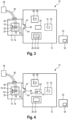
- Fig. 1 shows a schematic representation 10 of a first embodiment of a transfer system 10 according to a second aspect of the invention.
- the transfer system 10 of the first embodiment comprises an isolator 12, in particular an aseptic isolator 12, with a transfer lock 14.
- a first needle carrier 16 can be arranged, which carries a number of filling needles 18, wherein preferably at least one filling needle 20 of the number of filling needles 18 has a circular cylindrical shape (see also Fig. 5A and Fig. 5B
- a filling needle shape is not limited to circular cylindrical shapes.
- other common filling needle shapes e.g., triangular, elliptical, polygonal, or similar are also possible.
- a second needle carrier 22 can be arranged in a first position 24 within the aseptic isolator 12.
- the second needle carrier 22 is preferably arranged in a filling station 26, in which objects or end containers (e.g., vials, cartridges, bottles, syringes, and/or the like) can be filled with a fluid, in particular a pharmaceutical or cosmetic fluid, by means of the at least one filling needle 20 of the plurality of filling needles 18.
- the transfer system 10 of the first embodiment comprises at least one robot 28 with at least one robot end effector 29.
- the at least one robot 28 comprises a support structure (not shown), in particular an articulated one, at the end of which a robot end effector is arranged.
- the support structure is designed to move the robot end effector in all three spatial directions.
- two or more, preferably identical, robots 28 can be arranged within the isolator 12.
- a first robot 28 with at least one first Robot end effector 29 can be arranged closer to the transfer lock 14, whereas an optional second robot 30 with at least one second robot end effector 31 can be arranged closer to the second needle carrier 22 (or the filling station 26).
- the robot end effector 29 is designed to directly hold at least one filling needle.
- the at least one filling needle can be held, for example, mechanically, in particular positively or non-positively, or magnetically.
- the at least one filling needle can be held robotically by means of a detachable clip connection.
- the robot end effector 29 preferably has one or more grippers 56, 58, which allow a targeted gripping of at least one filling needle 20 (shown as an example in Fig. 5A ).
- the at least one robot 28 can be controlled by a controller 32, which has a computer program 34 with a program code.
- the controller 32 is shown as a standalone, separate unit. Alternatively, the controller 32 can also be integrated into the aseptic isolator 12.
- the number of filling needles 18 can be in fluid communication with a source container 38, preferably containing a pharmaceutical or cosmetic fluid, via a number of tubes 36.
- the transfer lock 14 is preferably designed such that the number of tubes 36 traverse a wall 40 of the transfer lock 14 in a sterile manner, for example, through appropriate sealing means.
- a conveying means e.g., at least one pump
- conveying the fluid is preferably arranged between the number of filling needles and the source container. This can be, for example, a peristaltic pump, a rotary piston pump, or the like.
- the aseptic isolator 12 and the transfer lock 14 share a common wall section 42.
- An opening 44 which corresponds to the alpha port explained above, extends through the common wall section 42.
- the aseptic isolator 42 has a door 46 designed to releasably lock the opening 44.
- the door 46 is shown as pivotable. Alternatively, however, the door 46 can also be designed as a sliding door, which represents a space-saving alternative to the pivoting door.
- the transfer of at least one filling needle 20 of the number of filling needles 18 into the aseptic isolator 12 according to the invention can be carried out while maintaining a germ-free environment within the transfer lock 14 and within the aseptic isolator 12.
- the opening and closing of the door 46 can preferably be carried out by means of the robot end effector 29.
- glove passages (not shown) can also be provided in the aseptic isolator 12 for this purpose.
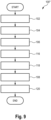
- a method 100 according to a first embodiment of the first aspect of the invention can be carried out.
- the first needle carrier 16, which carries the number of filling needles 18, is provided within the transfer lock 14.
- the number of filling needles 18 is arranged in the first needle carrier 16.
- the first needle carrier 16, together with the number of filling needles 18 arranged therein, is arranged in the transfer lock 14, which is designed, for example, as a sterile bag or as a rigid transport container, before the transfer lock 14 is sterilely coupled to the alpha port of the aseptic isolator 14.
- the number of filling needles 18 can be arranged in a regular or irregular arrangement in the first needle carrier 16.
- a regular arrangement can be, for example, a linear, regular arrangement (e.g., in the form of a matrix) or a circular, regular arrangement (e.g., in the form of a circular pattern).
- the second needle carrier 22 is provided in the first position 24 within the aseptic isolator 12.
- the second needle carrier 22 is preferably introduced into the aseptic isolator 12 in a pre-sterilized state and positioned in the first position 24 either robotically or manually.
- the second needle carrier 22 can, for example, be introduced into the aseptic isolator 12 in a sterile manner via the opening 44.
- the second needle carrier 22 has receptacles (e.g. through holes) for carrying at least one filling needle 20.
- receptacles can, for example, be identical to the receptacles of the first needle carrier 16, so that, for example, Filling needle spacing and/or a filling needle arrangement of the first needle carrier 16 and the second needle carrier 22 are identical.
- the receptacles of the needle carrier 16 and those of the needle carrier 22 can be different.
- the first needle carrier 16 to carry more filling needles than the second needle carrier 22.
- At least one filling needle 20 of the number of filling needles 18 is transferred from the first needle carrier 16 to the second needle carrier 22 by robot support.
- step 106 is performed such that the robot end effector 29 removes the at least one filling needle 20 from the plurality of filling needles 18 in its entirety or simultaneously from the first needle carrier 16 and transfers it to the second needle carrier 22.
- the at least one filling needle 20 is directly grasped and removed from the first needle carrier.
- the entire transfer of the at least one filling needle 20 proves to be particularly advantageous when the first needle carrier 16 and the second needle carrier 22 are essentially identical, i.e., have the same filling needle spacing and the same filling needle arrangement.
- step 106 occurs such that the robot end effector 29 individually removes the at least one filling needle 20 from the number of filling needles 18 and transfers it to the second needle carrier 22.
- the at least one filling needle 20 is held directly by the robot end effector 29.
- the individual transfer of the at least one filling needle 20 proves to be particularly advantageous when the first needle carrier 16 and the second needle carrier 22 differ with regard to the filling needle spacing and/or the filling needle arrangement.
- the opening of the transfer lock 14 can be carried out robot-assisted, ie by means of the robot end effector 29.
- the door 46 can, for example, have a counter-receptacle 47, in particular of circular cylindrical design, which is connected to the Robot end effector 29 can be grasped or otherwise detected. This can further increase the degree of automation of the method 100.
- the at least one filling needle 20 is arranged in the second needle carrier 22 with robot support.
- the at least one filling needle 20 of the plurality of filling needles 18 is held directly by the robot end effector 29.
- the needle carrier 22 can be in the first position 24 in a filling station 26, in which objects are filled with a fluid, in particular a pharmaceutical or cosmetic fluid, by means of the at least one filling needle 20 of the plurality of filling needles 18.
- the objects are preferably positioned directly below the at least one filling needle 20.
- Fig. 2 shows a schematic representation of a second embodiment of the transfer system 10 according to the second aspect of the invention.
- the transfer system 10 of the second embodiment essentially corresponds to the transfer system 10 of the first embodiment. Identical elements are designated by the same reference numerals and will not be explained in detail.
- the transfer system 10 of the second embodiment differs from the transfer system 10 of the first embodiment by a third needle carrier 48, which can be arranged in a second position 50 within the aseptic isolator 12. The second position 50 is spaced from the first position 24.
- the third needle carrier 48 is preferably an intermediate carrier in which the at least one filling needle 20 is carried before it is transferred to the second needle carrier 22.
- a method 100' according to a second embodiment of the first aspect of the invention can be carried out.
- the first needle carrier 16 which carries the number of filling needles 18, is provided within the transfer lock 14.
- the number of filling needles 18 is arranged in the first needle carrier 16.
- the first needle carrier 16 together with the number of filling needles 18 arranged therein is Transfer lock 14, which is designed, for example, as a sterile bag or as a rigid transport container, is arranged before the transfer lock 14 is sterilely coupled to the alpha port of the aseptic isolator 14.
- the number of filling needles 18 can be arranged in a regular or irregular arrangement in the first needle carrier 16.
- a regular arrangement can, for example, be a linear, regular arrangement (e.g., in the form of a matrix) or a circular, regular arrangement (e.g., in the form of a circular pattern).
- the second needle carrier 22 is provided in the first position 24 within the aseptic isolator 12.
- the second needle carrier 22 is preferably introduced into the aseptic isolator 12 in a pre-sterilized state and positioned in the first position 24 either robotically or manually.
- the second needle carrier 22 can, for example, be introduced into the aseptic isolator 12 in a sterile manner via the opening 44.
- the second needle carrier 22 has receptacles (e.g., through holes) for supporting at least one filling needle 20.
- receptacles can, for example, be identical to the receptacles of the first needle carrier 16, so that, for example, the filling needle spacing and/or the filling needle arrangement of the first needle carrier 16 and the second needle carrier 22 are identical.
- the receptacles of the needle carrier 16 and the needle carrier 22 can be different.
- the first needle carrier 16 to support more filling needles than the second needle carrier 22.
- At least one filling needle 20 of the number of filling needles 18 is transferred from the first needle carrier 16 to the second needle carrier 22 in a robot-assisted manner.
- a first step 110 the at least one filling needle 20 of the number of filling needles 18 is first transferred from the first needle carrier 16 to the third needle carrier 48 by robot support.
- the at least one filling needle 20 is held directly by the robot end effector and can be transferred either as a whole or individually from the first needle carrier 16 to the third needle carrier 48.
- at least one filling needle 20 of the number of filling needles 18 grasped in step 110 is arranged in the third needle carrier 48 in a robot-assisted manner.
- the at least one filling needle 20 is arranged in the second needle carrier 22 with robot support.
- the at least one filling needle 20 of the plurality of filling needles 18 is held directly by the robot end effector 29.
- the needle carrier 22 can be in the first position 24 in a filling station 26, in which objects are filled with a fluid, in particular a pharmaceutical or cosmetic fluid, by means of the at least one filling needle 20 of the plurality of filling needles 18.
- the objects are preferably positioned directly below the at least one filling needle 20.
- the step 108 is carried out by means of a second robot-assisted transfer 114 of the at least one filling needle 20 of the number of filling needles 18 from the third needle carrier 48 to the second needle carrier 22, wherein the at least one filling needle 20 of the number of filling needles 18 is held directly during the second robot-assisted transfer 114.
- the at least one filling needle 20 of the number of filling needles 18 is transferred as a whole from the first needle carrier 16 to the third needle carrier 48, the at least one filling needle 20 of the number of filling needles 18 is transferred individually from the third needle carrier 48 to the second needle carrier 22.
- This configuration is advantageous, for example, when the first needle carrier 16 and the third needle carrier 48 are substantially identical, with the third needle carrier 48 and the second needle carrier 22 differing with regard to the filling needle spacing and/or the filling needle arrangement.
- the at least one filling needle 20 of the number of filling needles 18 is transferred individually from the first needle carrier 16 to the third needle carrier 48, the at least one filling needle 20 of the number of filling needles 18 is transferred as a whole from the third needle carrier 48 to the second needle carrier 22.
- This configuration is advantageous, for example, when the third needle carrier 48 and the second needle carrier 22 do not differ with regard to the filling needle spacing and/or the filling needle arrangement. (ie are substantially identical), wherein the first needle carrier 16 and the third needle carrier 48 differ in terms of the filling needle spacing and/or the filling needle arrangement.
- the transfer lock 14 can be opened with robot support, i.e., by means of the robot end effector 29.
- the door 46 can, for example, have a counter-receptacle 47, in particular one with a circular cylindrical shape, which can be grasped or otherwise engaged by the robot end effector 29. This can further increase the degree of automation of the method 100.
- Fig. 3 shows a schematic representation of a third embodiment of the transfer system 10 according to the second aspect of the invention.
- the transfer system 10 of the third embodiment essentially corresponds to the transfer system 10 of the first embodiment. Identical elements are identified by the same reference numerals and will not be explained in detail.
- the transfer system 10 of the third embodiment differs from the transfer system 10 of the first embodiment by the optional configuration of the first needle carrier 16.
- the first needle carrier 16 can (optionally) have at least one projection 52.
- the at least one projection 52 preferably extends from a base body 62 of the first needle carrier 16.
- Each of the at least one projection 52 is shaped such that a robot gripper 56 (shown as an example in Fig. 5A and 5B ) of a robot end effector 29, which is designed to receive or hold a single filling needle 20 of the number of filling needles 18 or an object to be filled by means of the single filling needle 20 of the number of filling needles 18, in particular a pharmaceutical or cosmetic object.
- Each of the at least one projection 52 can, for example, have a circular cylindrical shape.
- the shape of the projection is not limited to circular cylindrical shapes. Other shapes (e.g. prismatic or triangular, rectangular or cuboid-shaped or the like) are possible. It goes without saying that the robot end effector 29 can, for example, have several grippers 56, 58, each of which can grasp "a single" filling needle 20 of the number of filling needles 18 (e.g., shown in Fig. 5A ).
- the first needle carrier 16 can also be designed without such a projection 52.
- a method 100" according to a third embodiment of the first aspect of the invention can be carried out.
- the first needle carrier 16, which carries the number of filling needles 18, is provided within the transfer lock 14.
- the number of filling needles 18 is arranged in the first needle carrier 16.
- the first needle carrier 16, together with the number of filling needles 18 arranged therein, is arranged in the transfer lock 14, which is designed, for example, as a sterile bag or as a rigid transport container, before the transfer lock 14 is sterilely coupled to the alpha port of the aseptic isolator 14.
- the number of filling needles 18 can be arranged in a regular or irregular arrangement in the first needle carrier 16.
- a regular arrangement can be, for example, a linear, regular arrangement (e.g., in the form of a matrix) or a circular, regular arrangement (e.g., in the form of a circular pattern).
- the second needle carrier 22 is provided in the first position 24 within the aseptic isolator 12.
- the second needle carrier 22 is preferably introduced into the aseptic isolator 12 in a pre-sterilized state and positioned in the first position 24 either robotically or manually.
- the second needle carrier 22 can, for example, be introduced into the aseptic isolator 12 in a sterile manner via the opening 44.
- the second needle carrier 22 has receptacles (e.g. through holes) for carrying at least one filling needle 20.
- receptacles can, for example, be identical to the receptacles of the first needle carrier 16, so that, for example, filling needle spacing and/or a filling needle arrangement of the first needle carrier 16 and the second needle carrier 22 are identical.
- the receptacles of the first needle carrier 16 and those of the second needle carrier 22 can be different. It is also possible for the first needle carrier 16 to carry more filling needles than the second needle carrier 22.
- a first step 116 the first needle carrier 16, together with the number of filling needles 18, is transferred from the transfer lock 14 to a second position 50 within the aseptic isolator 12 by robot support, wherein the second position 50 is spaced from the first position 22.
- the first needle carrier 16 from step 116 is arranged in the second position 50.
- the at least one filling needle 20 is arranged in the second needle carrier 22 with robot support.
- the at least one filling needle 20 of the plurality of filling needles 18 is held directly during this process.
- the needle carrier 22 can be in the first position 24 in a filling station 26, in which objects are filled with a fluid, in particular a pharmaceutical or cosmetic fluid, by means of the at least one filling needle 20 of the plurality of filling needles 18.
- the objects are preferably positioned directly below the at least one filling needle 20.
- Step 108 is performed by means of a second robot-assisted transfer 120 of the at least one filling needle 20 of the plurality of filling needles 18 from the first needle carrier 16, which is arranged at this time in position 50, to the second needle carrier 22, wherein the at least one filling needle 20 of the plurality of filling needles 18 is directly held during the second robot-assisted transfer 120.
- the step of second transfer 120 takes place starting from the first needle carrier 16 arranged in the second position 50.
- the at least one filling needle 20 of the number of filling needles 18 can be transferred as a whole or individually from the first needle carrier 16 arranged in the second position 50 to the second needle carrier 22.
- the transfer lock 14 can be opened with robot support, i.e., by means of the robot end effector 29.
- the door 46 can, for example, have a counter-receptacle 47, in particular one with a circular cylindrical shape, which can be grasped or otherwise engaged by the robot end effector 29. This can further increase the degree of automation of the method 100.
- Fig. 4 shows a schematic representation of a transfer system 10 according to a second example.
- the transfer system 10' according to the second example essentially corresponds to the transfer system 10 of the third embodiment of the second aspect of the invention. Identical elements are identified by the same reference numerals and will not be explained in detail.
- One difference from the transfer system 10 of the third embodiment of the second aspect is that the needle carrier 16 according to the transfer system 10' has a receptacle 52'.
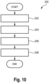
- a method 200 according to an embodiment of the first example of the invention may be carried out.
- the needle carrier 16 is picked up via the receptacle 52' by means of the robot end effector 29, 31.
- the needle carrier 16 carries the number of filling needles.
- the robot end effector 29, 31 is designed to pick up both a single filling needle 20 of the number of filling needles 18 or an object to be filled using the single filling needle 20, in particular a pharmaceutical or cosmetic object, as well as the at least one projection 52'.
- the picking up of the needle carrier can be carried out mechanically, in particular positively or non-positively, or magnetically.
- the receptacle 52' of the needle carrier 16 can be picked up with robot support using a detachable clip connection.
- the receptacle 52' can also be grasped by means of a robot gripper. Magnetic picking up of the needle carrier 16 via the receptacle 52' is also possible.
- the needle carrier 16 received via the holder 52', together with the number of filling needles 18, is transferred by robot support into a filling position 24 in the aseptic isolator 12.
- the needle carrier 16 is provided with the number of filling needles 18 within the transfer lock 14. In other words, this means that the needle carrier 16 is initially located in the transfer lock 14. Starting from the transfer lock 14, it is picked up by the robot via the receptacle 52' and transferred to the filling position 24.
- the needle carrier 16 is provided in a position 50' within the isolator, spaced apart from the filling position 24.
- a transfer lock needle carrier 16' is provided within the transfer lock 14.
- the transfer lock needle carrier 16' initially carries the number of filling needles 18.
- the number of filling needles 18 is transferred from the transfer lock needle carrier 16' to the needle carrier 16, which is located in position 50', in a robotic manner.
- the number of filling needles 18 is held directly by a robot end effector.
- the removed number of filling needles 18 is arranged in the needle carrier 16 in a robotic manner.
- the number of filling needles can be transferred either individually or as a whole from the transfer lock needle carrier 16' to the needle carrier 16.
- the needle carrier 16 can be transferred by more than one robot 28, 30.
- the needle carrier 16 can be transferred from one robot 28 to another robot 30.
- the opening of the transfer lock 14 can be robot-assisted, ie, by means of the robot end effector 29, 31.
- the door 46 can, for example, have a counter-receptacle 47, in particular one with a circular cylindrical shape, which can be grasped or otherwise detected by the robot end effector 29.
- the counter-receptacle 47 is preferably circular cylindrical. This allows the degree of automation of the method 100 can be further increased and interaction with the robot end effector 29, 31 can be further simplified.
- the Fig. 5A and 5B show an isometric view of an embodiment of a robot end effector 29, 31 according to the invention.
- the robot end effector 29, 31 is connected to a robot 28, 30 by means of a preferably articulated support structure (not shown).
- the support structure is designed to move the robot end effector in all three spatial directions and can have one or more joints for this purpose.
- the support structure can, for example, be a construction with multi-axis movements of any kind. For example, such a construction can have two- to six-axis movements of any kind.
- the first gripper 56 has a first leg 56-1 and a second leg 56-2, wherein the first leg 56-1 and the second leg 56-2 are movable relative to one another.
- the first gripper 56 extends from the main body 54 and has a recess at a gripping portion 60.
- the recess is designed such that preferably circular-cylindrical or tubular elements can be gripped.
- the recess can be curved, angular, or circular-cylindrical in shape to center the circular-cylindrical or tubular elements.
- the robot end effector 29, 31 is preferably designed to grip a single filling needle 20, an object to be filled by means of the single filling needle 20 (not shown) and/or a needle carrier 16.
- Fig. 6 shows an isometric view of an embodiment of the robot end effector 29, 31 according to the invention, which, for example, grips a needle carrier 16 via the preferably circular-cylindrical receptacle 52 by means of the first gripper 56.
- the receptacle 52 is designed as a projection that extends from a base body 62 of the needle carrier 16.
- the projection 52 is shaped such that a robot end effector that is designed to grip a single filling needle of the number of filling needles or an object to be filled using the single filling needle, in particular an object for receiving a pharmaceutical or cosmetic fluid or liquid, can also grip the projection.
- Such objects generally have a circular-cylindrical shape, so that the cross-section to be gripped is circular.
- the projection 52 can also have a circular cross-section.
- the needle carrier 16 can then be gripped with the same end effector 29, 31 with which the at least one needle 20 itself can also be gripped. Changing the end effector 29, 31 can therefore be avoided, even if the transfer process for transferring the at least one filling needle 20 into the aseptic isolator 12 changes.
- the needle carrier according to the invention is not limited to one projection.
- the needle carrier 16 can, for example, have two or more such projections.
- Fig. 6 shows an isometric representation of an embodiment of a needle carrier 16 according to the invention in a transfer lock (not shown), which in this case is coupled, by way of example, to the alpha port of the aseptic isolator.
- the alpha port has a recess 44 and a door 46.
- the door 46 is attached (in particular pivotably) to the alpha port in such a way that the opening 44 can be releasably locked by the door 46.
- a needle carrier 16 according to the invention is provided within the transfer lock 14. This carries a number of filling needles 18 provided with tubes 36. The number of filling needles can be carried in different ways.
- the needle carrier 16 can have at least one through-hole for carrying at least one filling needle 20 therein.
- the at least one filling needle 20 can be magnetically arranged in or on the needle carrier 16. It can also be provided that the at least one filling needle is arranged in a form-fitting manner in or on the needle carrier (e.g. by means of a clip or snap connection).
- a difference to the one in Fig. 5B shown needle carrier is that the Fig. 6
- the needle carrier 16 shown has, for example, two projections 52.
- the number of projections 52 can also be more than two. This can ensure additional anti-twist protection of the needle carrier when it is held by a robot.
- a corresponding robot end effector 29, 31 preferably has a number of robot grippers 56, 58 ( Fig. 5A and 5B ), by means of which the number of projections 52 can be accommodated, in particular simultaneously.
- a filling needle spacing d1 i.e., a distance between adjacent filling needles 20
- the method 150 according to the fourth aspect of the invention can be carried out complementarily to the method according to the first aspect of the invention.
- the method according to the fourth aspect of the invention can be understood as a reversion of the method according to the first aspect of the invention.
- the method 150 according to the fourth aspect of the invention can also be carried out independently of the method according to the first aspect of the invention.
- the method 150 according to the fourth aspect of the invention can be implemented in the previously described system 10 (see Fig. 1 to Fig. 3 ) can be executed.
- the first needle carrier 16 is provided.
- the first needle carrier 16 can be arranged, for example, in the transfer lock 14. As in the embodiment according to Fig. 3 As shown, the first needle carrier 16 can also be arranged in the second position 50.
- the second needle carrier 22 is provided in the first position 24 within the insulator 12.
- the second needle carrier 22 preferably carries the number of filling needles 18.
- a further step 156 at least one filling needle 20 of the number of filling needles 18 is removed from the second needle carrier 22.
- the at least one filling needle 20 of the number of filling needles 18 is held directly by the robot end effector 29, 31 during the robot-assisted removal 108.
- the at least one filling needle 20 of the number of filling needles 18 is transferred from the second needle carrier 16 to the first needle carrier 22 in a robot-assisted manner.
- the transfer lock 14 can be closed robotically, i.e. by means of the robot end effector 29, 31, via the counter-receiver 47 of the door 46.
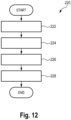
- Fig. 12 shows a schematic representation of a method 220 according to a fourth example.
- the method 220 according to the fourth example can be carried out complementarily to the method according to the first example.
- the method according to the fourth example can be understood as a reversion of the method according to the first example.
- the method 220 according to the fourth example can also be carried out independently of the method according to the first example.
- the method 220 according to the fourth example can be implemented in the previously described system 10' (see Fig. 4 ) can be executed.
- a first step 222 the needle carrier 16 is provided in the filling position 24.
- the needle carrier 16 is picked up by a robot via the receptacle 52.
- the needle carrier 16 preferably carries the number of filling needles 18.
- the needle carrier 16 is removed from the filling position 24 in the isolator 12.
- the needle carrier 16 with the number of filling needles 18 is transferred from the filling position.
- the transfer lock 14 can be closed robotically, i.e. by means of the robot end effector 29, 31, via the counter-receiver 47 of the door 46.
Landscapes
- Engineering & Computer Science (AREA)
- Mechanical Engineering (AREA)
- Robotics (AREA)
- Chemical & Material Sciences (AREA)
- Clinical Laboratory Science (AREA)
- Health & Medical Sciences (AREA)
- Dispersion Chemistry (AREA)
- Chemical Kinetics & Catalysis (AREA)
- Filling Of Jars Or Cans And Processes For Cleaning And Sealing Jars (AREA)
- Manipulator (AREA)
- Basic Packing Technique (AREA)
- Automatic Assembly (AREA)
- Auxiliary Devices For And Details Of Packaging Control (AREA)
- Nonwoven Fabrics (AREA)
Claims (14)
- Procédé (100) permettant de transférer au moins une aiguille de remplissage (20) d'un certain nombre d'aiguilles de remplissage (18) dans un isolateur (12), en particulier un isolateur aseptique (12), qui présente un sas de transfert (14), dans lequel le procédé (100) présente les étapes suivantes :fourniture (102) d'un premier support pour aiguilles (16) à l'intérieur du sas de transfert (14), lequel premier support pour aiguilles supporte le certain nombre d'aiguilles de remplissage (18) ;fourniture (104) d'un deuxième support pour aiguilles (22) dans une première position (24) à l'intérieur de l'isolateur (12) ;transfert robotisé (106) de l'au moins une aiguille de remplissage (20) du certain nombre d'aiguilles de remplissage (18) du premier support pour aiguilles (16) au deuxième support pour aiguilles (22) ; etdisposition robotisée (108) de l'au moins une aiguille de remplissage (20) du certain nombre d'aiguilles de remplissage (18) dans le deuxième support pour aiguilles (22), dans lequel l'au moins une aiguille de remplissage (20) du certain nombre d'aiguilles de remplissage (18) est directement maintenue pendant la disposition robotisée (108).
- Procédé (100) selon la revendication 1, dans lequel le deuxième support pour aiguilles (22) est dans une station de remplissage (26) dans laquelle des objets sont remplis d'un fluide, en particulier d'un fluide pharmaceutique ou d'un fluide cosmétique, au moyen de l'au moins une aiguille de remplissage (20) du certain nombre d'aiguilles de remplissage (18).
- Procédé (100) selon la revendication 1 ou 2, dans lequel l'au moins une aiguille de remplissage (20) du certain nombre d'aiguilles de remplissage (18) est transférée en totalité du premier support pour aiguilles (16) au deuxième support pour aiguilles (22).
- Procédé (100) selon la revendication 1 ou 2, dans lequel l'au moins une aiguille de remplissage (20) du certain nombre d'aiguilles de remplissage (18) est transférée respectivement individuellement du premier support pour aiguilles (16) au deuxième support pour aiguilles (22).
- Procédé (100) selon la revendication 1 ou 2, dans lequel l'étape de transfert robotisé (106) de l'au moins une aiguille de remplissage (20) du certain nombre d'aiguilles de remplissage (18) du premier support pour aiguilles (16) au deuxième support pour aiguilles (22) présente les étapes suivantes :premier transfert robotisé (110) de l'au moins une aiguille de remplissage (20) du certain nombre d'aiguilles de remplissage (18) du premier support pour aiguilles (16) à un troisième support pour aiguilles (48) qui est disposé dans une seconde position (50) à l'intérieur de l'isolateur (12), dans lequel la seconde position (50) est espacée de la première position (24) ;disposition robotisée (112) de l'au moins une aiguille de remplissage (20) du certain nombre d'aiguilles de remplissage (18) dans le troisième support pour aiguilles (48) ; etdans lequel l'étape de disposition robotisée (108) de l'au moins une aiguille de remplissage (20) du certain nombre d'aiguilles de remplissage (18) dans le deuxième support pour aiguilles (22) présente l'étape suivante :
second transfert robotisé (114) de l'au moins une aiguille de remplissage (20) du certain nombre d'aiguilles de remplissage (18) du troisième support pour aiguilles (48) au deuxième support pour aiguilles (22), dans lequel l'au moins une aiguille de remplissage (20) du certain nombre d'aiguilles de remplissage (18) est directement maintenue pendant le second transfert robotisé (114). - Procédé (100) selon la revendication 5, dans lequel le troisième support pour aiguilles (48) est un support intermédiaire dans lequel l'au moins une aiguille de remplissage (20) est supportée avant d'être transférée dans le deuxième support pour aiguilles (22).
- Procédé (100) selon la revendication 5 ou 6, dans lequel l'au moins une aiguille de remplissage (20) du certain nombre d'aiguilles de remplissage (18) est transférée en totalité du premier support pour aiguilles (16) au troisième support pour aiguilles (48).
- Procédé (100) selon la revendication 5 ou 6, dans lequel l'au moins une aiguille de remplissage (20) du certain nombre d'aiguilles de remplissage (18) est transférée respectivement individuellement du premier support pour aiguilles (16) au troisième support pour aiguilles (48).
- Procédé (100) selon la revendication 1 ou 2, dans lequel l'étape de transfert robotisé (106) de l'au moins une aiguille de remplissage (20) du certain nombre d'aiguilles de remplissage (18) du premier support pour aiguilles (16) au deuxième support pour aiguilles (22) présente les étapes suivantes :premier transfert robotisé (116) du premier support pour aiguilles (16) avec le certain nombre d'aiguilles de remplissage (18) du sas de transfert (14) à une seconde position (50) à l'intérieur de l'isolateur (12), dans lequel la seconde position (50) est espacée de la première position (22) ;disposition robotisée (118) du premier support pour aiguilles (16) dans la seconde position (50) ; etdans lequel l'étape de disposition robotisée (108) de l'au moins une aiguille de remplissage (20) du certain nombre d'aiguilles de remplissage (18) dans le deuxième support pour aiguilles (22) présente l'étape suivante :
second transfert robotisé (120) de l'au moins une aiguille de remplissage (20) du certain nombre d'aiguilles de remplissage (18) du premier support pour aiguilles (16) au deuxième support pour aiguilles (22), dans lequel l'au moins une aiguille de remplissage (20) du certain nombre d'aiguilles de remplissage (18) est directement maintenue pendant le second transfert robotisé (120). - Procédé (150) permettant de transférer au moins une aiguille de remplissage (20) d'un certain nombre d'aiguilles de remplissage (18) hors d'un isolateur (12), en particulier d'un isolateur aseptique (12), qui présente un sas de transfert (14), dans lequel le procédé (150) présente les étapes suivantes :fourniture (152) d'un premier support pour aiguilles (16) à l'intérieur du sas de transfert (14) ;fourniture (154) d'un deuxième support pour aiguilles (22) dans une première position (24) à l'intérieur de l'isolateur (12), lequel deuxième support pour aiguilles supporte le certain nombre d'aiguilles de remplissage (18) ;extraction robotisée (156) de l'au moins une aiguille de remplissage (20) du certain nombre d'aiguilles de remplissage (18) hors du deuxième support pour aiguilles (22), dans lequel l'au moins une aiguille de remplissage (20) du certain nombre d'aiguilles de remplissage (18) est directement maintenue pendant l'extraction robotisée (156) ; ettransfert robotisé (158) de l'au moins une aiguille de remplissage (20) du certain nombre d'aiguilles de remplissage (18) du deuxième support pour aiguilles (16) au premier support pour aiguilles (22).
- Système de transfert (10) permettant de transférer au moins une aiguille de remplissage (20) d'un certain nombre d'aiguilles de remplissage (18) dans un isolateur (12), en particulier un isolateur aseptique (12), dans lequel le système de transfert (10) présente :l'isolateur (12) qui présente un sas de transfert (14), dans lequel un premier support pour aiguilles (16) qui supporte le certain nombre d'aiguilles de remplissage (18) est fourni à l'intérieur du sas de transfert (14), et dans lequel un deuxième support pour aiguilles (22) est fourni dans une première position (24) à l'intérieur de l'isolateur (12) ;au moins un robot (28, 30) comportant un organe effecteur de robot (29, 31) qui est disposé à l'intérieur de l'isolateur (12) ; etune commande (32) qui est configurée de telle sorte que les étapes suivantes sont exécutées :transfert robotisé (106) de l'au moins une aiguille de remplissage (20) du certain nombre d'aiguilles de remplissage (18) du premier support pour aiguilles (16) au deuxième support pour aiguilles (22) ; etdisposition robotisée (108) de l'au moins une aiguille de remplissage (20) du certain nombre d'aiguilles de remplissage (18) dans le deuxième support pour aiguilles (22), dans lequel l'au moins une aiguille de remplissage (20) du certain nombre d'aiguilles de remplissage (18) est directement maintenue par l'organe effecteur de robot (29, 31) pendant la disposition robotisée (108).
- Système de transfert (10) permettant de transférer au moins une aiguille de remplissage (20) d'un certain nombre d'aiguilles de remplissage (18) hors d'un isolateur (12), en particulier d'un isolateur aseptique (12), dans lequel le système de transfert (10) présente :l'isolateur (12) qui présente un sas de transfert (14), dans lequel un deuxième support pour aiguilles (22) est fourni dans une première position (24) à l'intérieur de l'isolateur (12), dans lequel le deuxième support pour aiguilles (22) supporte le certain nombre d'aiguilles de remplissage (18) ;un premier support pour aiguilles (16) qui est disposé à l'intérieur du sas de transfert (14) ;au moins un robot (28, 30) comportant un organe effecteur de robot (29, 31) qui est disposé à l'intérieur de l'isolateur (12) ; etune commande (32) qui est configurée de telle sorte que les étapes suivantes sont exécutées :extraction robotisée (156) de l'au moins une aiguille de remplissage (20) du certain nombre d'aiguilles de remplissage (18) hors du deuxième support pour aiguilles (22), dans lequel l'au moins une aiguille de remplissage (20) du certain nombre d'aiguilles de remplissage (18) est directement maintenue par l'organe effecteur de robot (29, 31) pendant l'extraction robotisée (156) ; ettransfert robotisé (158) de l'au moins une aiguille de remplissage (20) du certain nombre d'aiguilles de remplissage (18) du deuxième support pour aiguilles (16) au premier support pour aiguilles (22).
- Programme informatique (34) comportant un code de programme qui est configuré pour exécuter, lorsqu'il est exécuté dans la commande (32) du système de transfert (10) selon la revendication 11, les étapes suivantes :transfert robotisé (106) de l'au moins une aiguille de remplissage (20) du certain nombre d'aiguilles de remplissage (18) du premier support pour aiguilles (16) au deuxième support pour aiguilles (22) ; etdisposition robotisée (108) de l'au moins une aiguille de remplissage (20) du certain nombre d'aiguilles de remplissage (18) dans le deuxième support pour aiguilles (22), dans lequel l'au moins une aiguille de remplissage (20) du certain nombre d'aiguilles de remplissage (18) est directement maintenue pendant la disposition robotisée (108).
- Programme informatique (34) comportant un code de programme qui est configuré pour exécuter, lorsqu'il est exécuté dans la commande du système de transfert (10) selon la revendication 12, les étapes suivantes :extraction robotisée (156) de l'au moins une aiguille de remplissage (20) du certain nombre d'aiguilles de remplissage (18) hors du deuxième support pour aiguilles (22), dans lequel l'au moins une aiguille de remplissage (20) du certain nombre d'aiguilles de remplissage (18) est directement maintenue pendant l'extraction robotisée (108) ; ettransfert robotisé (158) de l'au moins une aiguille de remplissage (20) du certain nombre d'aiguilles de remplissage (18) du deuxième support pour aiguilles (16) au premier support pour aiguilles (22).
Priority Applications (2)
| Application Number | Priority Date | Filing Date | Title |
|---|---|---|---|
| EP24158132.1A EP4350713B1 (fr) | 2020-02-04 | 2021-02-02 | Procédé, système et programme informatique de transfert d'au moins une aiguille de remplissage d'un certain nombre d'aiguilles de remplissage dans un isolateur aseptique |
| EP25205251.9A EP4651155A3 (fr) | 2020-02-04 | 2021-02-02 | Procédé, système et programme informatique pour transférer au moins une aiguille de remplissage d'un certain nombre d'aiguilles de remplissage dans un isolateur aseptique |
Applications Claiming Priority (2)
| Application Number | Priority Date | Filing Date | Title |
|---|---|---|---|
| DE102020102765.6A DE102020102765A1 (de) | 2020-02-04 | 2020-02-04 | Verfahren zum Transferieren zumindest einer Füllnadel einer Anzahl von Füllnadeln in einen aseptischen Isolator |
| PCT/EP2021/052443 WO2021156261A1 (fr) | 2020-02-04 | 2021-02-02 | Procédé de transfert d'au moins une aiguille de remplissage d'un certain nombre d'aiguilles de remplissage dans un isolateur aseptique |
Related Child Applications (3)
| Application Number | Title | Priority Date | Filing Date |
|---|---|---|---|
| EP25205251.9A Division EP4651155A3 (fr) | 2020-02-04 | 2021-02-02 | Procédé, système et programme informatique pour transférer au moins une aiguille de remplissage d'un certain nombre d'aiguilles de remplissage dans un isolateur aseptique |
| EP24158132.1A Division EP4350713B1 (fr) | 2020-02-04 | 2021-02-02 | Procédé, système et programme informatique de transfert d'au moins une aiguille de remplissage d'un certain nombre d'aiguilles de remplissage dans un isolateur aseptique |
| EP24158132.1A Division-Into EP4350713B1 (fr) | 2020-02-04 | 2021-02-02 | Procédé, système et programme informatique de transfert d'au moins une aiguille de remplissage d'un certain nombre d'aiguilles de remplissage dans un isolateur aseptique |
Publications (3)
| Publication Number | Publication Date |
|---|---|
| EP4100326A1 EP4100326A1 (fr) | 2022-12-14 |
| EP4100326C0 EP4100326C0 (fr) | 2025-04-02 |
| EP4100326B1 true EP4100326B1 (fr) | 2025-04-02 |
Family
ID=74550664
Family Applications (3)
| Application Number | Title | Priority Date | Filing Date |
|---|---|---|---|
| EP24158132.1A Active EP4350713B1 (fr) | 2020-02-04 | 2021-02-02 | Procédé, système et programme informatique de transfert d'au moins une aiguille de remplissage d'un certain nombre d'aiguilles de remplissage dans un isolateur aseptique |
| EP21703243.2A Active EP4100326B1 (fr) | 2020-02-04 | 2021-02-02 | Procédé de transfert d'au moins une aiguille de remplissage d'un certain nombre d'aiguilles de remplissage dans un isolateur aseptique |
| EP25205251.9A Pending EP4651155A3 (fr) | 2020-02-04 | 2021-02-02 | Procédé, système et programme informatique pour transférer au moins une aiguille de remplissage d'un certain nombre d'aiguilles de remplissage dans un isolateur aseptique |
Family Applications Before (1)
| Application Number | Title | Priority Date | Filing Date |
|---|---|---|---|
| EP24158132.1A Active EP4350713B1 (fr) | 2020-02-04 | 2021-02-02 | Procédé, système et programme informatique de transfert d'au moins une aiguille de remplissage d'un certain nombre d'aiguilles de remplissage dans un isolateur aseptique |
Family Applications After (1)
| Application Number | Title | Priority Date | Filing Date |
|---|---|---|---|
| EP25205251.9A Pending EP4651155A3 (fr) | 2020-02-04 | 2021-02-02 | Procédé, système et programme informatique pour transférer au moins une aiguille de remplissage d'un certain nombre d'aiguilles de remplissage dans un isolateur aseptique |
Country Status (5)
| Country | Link |
|---|---|
| US (2) | US12552053B2 (fr) |
| EP (3) | EP4350713B1 (fr) |
| DE (1) | DE102020102765A1 (fr) |
| ES (2) | ES3059847T3 (fr) |
| WO (1) | WO2021156261A1 (fr) |
Families Citing this family (12)
| Publication number | Priority date | Publication date | Assignee | Title |
|---|---|---|---|---|
| EP3142085B1 (fr) * | 2015-09-12 | 2022-03-02 | Cleveron AS | Terminal de colis et procédé d'optimisation de la capacité en colis dans ledit terminal |
| IT201900006552A1 (it) | 2019-05-06 | 2020-11-06 | Ima Spa | Apparato e metodo per la gestione automatizzata di una camera di lavorazione ad atmosfera controllata. |
| EP3878612A1 (fr) * | 2020-03-12 | 2021-09-15 | Grifols Worldwide Operations Limited | Système et procédé de distribution d'un liquide dans une chambre fermée |
| DE102022100678A1 (de) | 2022-01-12 | 2023-07-13 | Tt Innovation Ag | Transfervorrichtung, Verfahren und Verwendung einer Transfervorrichtung zum Überführen wenigstens eines Funktionselements in eine Prozesskammer |
| DE102022131808A1 (de) * | 2022-11-30 | 2024-06-06 | Groninger & Co. Gmbh | Funktionselement, Beta-Behältersystem, Transfersystem und Barrieresystem |
| DE102023106539A1 (de) * | 2023-03-15 | 2024-09-19 | Syntegon Technology Gmbh | Transfersystem zur Verwendung in einem Isolator, Isolator und Produktionsanlage sowie Verfahren zu deren Betrieb |
| DE102023109926A1 (de) * | 2023-04-19 | 2024-10-24 | Bausch + Ströbel SE + Co. KG | Dosiervorrichtung für pharmazeutische Zwecke und Verfahren zum Betreiben einer Dosiervorrichtung |
| DE102023118665A1 (de) * | 2023-07-14 | 2025-01-16 | Syntegon Technology Gmbh | Befüllungssystem zur Fluidbefüllung von Behältnissen |
| DE102023122778A1 (de) | 2023-08-24 | 2025-02-27 | Syntegon Technology Gmbh | Pharmazeutische Anlage und Verfahren zum Betreiben einer pharmazeutischen Anlage |
| DE102023130785A1 (de) * | 2023-11-07 | 2025-05-08 | KyooBe Tech GmbH | Prozesseinheit zur Herstellung eines Produkts |
| IT202300024525A1 (it) | 2023-11-20 | 2025-05-20 | Ima Spa | Componente beta per un sistema di trasferimento, sistema di trasferimento, area di isolamento sterile, apparato di riempimento asettico e metodo per effettuare tale riempimento. |
| DE102024115999A1 (de) * | 2024-06-07 | 2025-12-11 | OPTIMA pharma GmbH | System und Verfahren zum Rüsten einer Anlage sowie Anlage |
Family Cites Families (78)
| Publication number | Priority date | Publication date | Assignee | Title |
|---|---|---|---|---|
| US2077774A (en) * | 1934-02-19 | 1937-04-20 | Fred F Rudder | Transfusion apparatus |
| US2672272A (en) * | 1949-11-26 | 1954-03-16 | Hoffmann La Roche | Apparatus for filling ampoules |
| US2687838A (en) * | 1951-01-29 | 1954-08-31 | Mallinckrodt Chemical Works | Ampoule filling device |
| US3957082A (en) * | 1974-09-26 | 1976-05-18 | Arbrook, Inc. | Six-way stopcock |
| US4111753A (en) * | 1976-06-07 | 1978-09-05 | National Appliance Company | Controlled atmosphere apparatus and method of transferring specimens to same |
| US4226235A (en) * | 1979-01-25 | 1980-10-07 | Survival Technology, Inc. | Plural injecting device |
| US4486188A (en) * | 1980-08-14 | 1984-12-04 | Applied Medical Devices, Inc. | Bone marrow transplant method and apparatus |
| US4578064A (en) * | 1983-12-21 | 1986-03-25 | Survival Technology Inc. | Plural dosage automatic injector with improved safety |
| GB2237816A (en) | 1989-11-09 | 1991-05-15 | Cambridge Isolation Tech | Isolator transfer containers |
| GB9325667D0 (en) * | 1993-12-15 | 1994-02-16 | Total Process Containment Ltd | Aseptic liquid barrier transfer coupling |
| US5460439A (en) * | 1994-01-07 | 1995-10-24 | Delaware Capital Formation, Inc. | Sealed transfer system |
| FR2719018B1 (fr) * | 1994-04-26 | 1996-07-12 | Py Daniel C | Procédé pour remplir dans des conditions aseptiques un récipient obturé. |
| DE29818721U1 (de) * | 1998-10-21 | 2000-03-02 | Medico Development Investment Co., Ascona | Injektionsgerät |
| FR2787235B1 (fr) * | 1998-12-11 | 2001-01-19 | Becton Dickinson France | Dispositif de liaison de portes entre deux enceintes isolees du milieu exterieur |
| DE10212008A1 (de) * | 2002-03-18 | 2003-10-09 | Aventis Behring Gmbh | Nadelhalter |
| ES2289313T3 (es) * | 2002-09-17 | 2008-02-01 | Glaxosmithkline Biologicals S.A. | Medios de sujecion de articulos y sistema de transporte. |
| DE10246061B4 (de) * | 2002-10-02 | 2012-09-06 | Robert Bosch Gmbh | Verfahren zum Befüllen von pharmazeutischen Behältnissen wie Ampullen, Vials o.ä. |
| US7094222B1 (en) * | 2003-04-28 | 2006-08-22 | The United States Of America As Represented By The Secretary Of Navy | Syringe device for simultaneous infusion and withdrawal |
| DE10345338B4 (de) * | 2003-09-21 | 2015-08-06 | Inova Pharma Systems Gmbh | Verfahren und Vorrichtung zum kontrollierten Befüllen |
| US7096896B2 (en) * | 2004-03-05 | 2006-08-29 | Medical Instill Technologies, Inc. | Apparatus and method for needle filling and laser resealing |
| US7783383B2 (en) * | 2004-12-22 | 2010-08-24 | Intelligent Hospital Systems Ltd. | Automated pharmacy admixture system (APAS) |
| DE102005018905B4 (de) * | 2005-04-20 | 2007-09-06 | Fette Gmbh | Transferschleuse für eine Tablettieranlage |
| US7850656B2 (en) * | 2005-04-29 | 2010-12-14 | Warsaw Orthopedic, Inc. | Devices and methods for delivering medical agents |
| US8151835B2 (en) * | 2006-08-23 | 2012-04-10 | Fht, Inc. | Automated drug delivery bag filling system |
| US20090028669A1 (en) * | 2007-07-25 | 2009-01-29 | Dynamic Micro Systems | Removable compartments for workpiece stocker |
| US20080206020A1 (en) * | 2007-02-27 | 2008-08-28 | Smith John M | Flat-panel display processing tool with storage bays and multi-axis robot arms |
| US20080279658A1 (en) * | 2007-05-11 | 2008-11-13 | Bachrach Robert Z | Batch equipment robots and methods within equipment work-piece transfer for photovoltaic factory |
| CH702317B1 (it) | 2007-08-02 | 2011-06-15 | Stevanato Group Internat As | Struttura di confezione di flaconi in vetro ad uso farmaceutico. |
| DE102008003105A1 (de) * | 2008-01-01 | 2009-07-02 | Lts Lohmann Therapie-Systeme Ag | Einweginjektor mit handbetätigbarem Kolben und einem Zweikammersystem |
| US20090223592A1 (en) | 2008-03-04 | 2009-09-10 | Vanrx Pharmaceuticals, Inc. | Robotic filling systems and methods |
| US20100084045A1 (en) * | 2008-10-03 | 2010-04-08 | Adams Richard H | Sterile liquid transfer port |
| US8919830B2 (en) * | 2008-11-05 | 2014-12-30 | West Pharmaceutical Services, Inc. | Barrier isolator port assembly |
| IT1394656B1 (it) * | 2009-07-03 | 2012-07-05 | Brev Angela Srl | Processo per la produzione e l'assemblaggio di una siringa per operazioni medicali |
| FR2956092B1 (fr) | 2010-02-10 | 2012-02-24 | Sartorius Stedim Biotech Sa | Procede et unite d'emplissage sterile d'un conteneur elementaire final avec un contenu destine au domaine biopharmaceutique. |
| DE202010004551U1 (de) * | 2010-04-01 | 2011-09-28 | Groninger & Co. Gmbh | Fülleinrichtung zum Füllen von insbesondere pharmazeutischen Produkten in Objekte |
| US8539989B2 (en) * | 2010-08-30 | 2013-09-24 | Health Robotics, S.r.l. | Method for the production of pharmaceutical products |
| US20120153610A1 (en) * | 2010-12-20 | 2012-06-21 | Thomas Mitchel Young | Aseptic transfer port |
| CN103608110B (zh) * | 2011-03-09 | 2017-06-06 | 彼克斯赛尔医疗科技有限公司 | 用于制备用于分析的包含细胞的样品流体的一次性盒子 |
| DE102011075146A1 (de) * | 2011-05-03 | 2012-11-08 | Legal Department, Ip Practice Group Agilent Technologies, Inc. | Kapillarende als sitz für einen probeninjektor |
| ES2481821T3 (es) * | 2011-06-17 | 2014-07-31 | Kiro Robotics S.L. | Máquina y método para la preparación automática de medicación intravenosa |
| KR101864294B1 (ko) | 2011-07-22 | 2018-06-04 | 반알엑스 파마시스템즈 인크. | 제어된 환경 인클로저 내에 유체 경로를 보호 및 보호 해제하는 방법 |
| US10684303B2 (en) * | 2011-07-22 | 2020-06-16 | Vanrx Pharmasystems Inc. | Method for protecting and unprotecting the fluid path in a controlled environment enclosure |
| CN103889388B (zh) * | 2011-10-31 | 2017-04-12 | 通用电气健康护理有限公司 | 刺穿和填充装置 |
| JPWO2014054183A1 (ja) * | 2012-10-05 | 2016-08-25 | 株式会社安川電機 | 自動調製システム |
| US9474691B2 (en) * | 2012-10-25 | 2016-10-25 | Yuyama Mfg. Co., Ltd. | Coinfusion apparatus |
| US9669552B2 (en) * | 2013-05-20 | 2017-06-06 | Varian Semiconductor Equipment Associates, Inc. | System and method for quick-swap of multiple substrates |
| JP5696822B1 (ja) * | 2013-07-01 | 2015-04-08 | 株式会社湯山製作所 | 混注管理装置、混注装置、混注管理プログラム |
| WO2015003145A1 (fr) * | 2013-07-03 | 2015-01-08 | Deka Products Limited Partnership | Appareil, système et procédé pour administrer un fluide |
| ES2718093T3 (es) * | 2013-08-16 | 2019-06-27 | Vanrx Pharmasystems Inc | Método para llenar envases farmacéuticos |
| CN105307621B (zh) * | 2013-09-19 | 2020-01-10 | 株式会社汤山制作所 | 混注装置和混注方法 |
| CN203937969U (zh) * | 2014-03-28 | 2014-11-12 | 奥星衡迅生命科技(上海)有限公司 | 用于隔离设备的转运袋 |
| DE102014106582B4 (de) * | 2014-05-09 | 2017-08-17 | Groninger GmbH & Co. KG | Füllnadel zum Befüllen eines Behälters mit einem Fluid |
| CA2947759C (fr) * | 2014-05-10 | 2018-11-20 | Dr. Py Institute Llc | Aiguille de remplissage a fermeture et ouverture automatiques, porte-aiguille, charge et procede |
| DE102014214697A1 (de) * | 2014-07-25 | 2016-01-28 | Robert Bosch Gmbh | Vorrichtung zum Befüllen eines Behältnisses |
| WO2016153590A2 (fr) * | 2015-01-22 | 2016-09-29 | The Regents Of The University Of California | Méthodes et dispositifs de séparation et d'élimination de plasma riche en plaquettes et de cellules d'aspirat de moelle osseuse |
| BR112017019272A2 (pt) * | 2015-03-10 | 2018-05-02 | Allergan Pharmaceuticals Holdings Ireland Unlimited Company | injetor de múltiplas agulhas |
| CA3007930A1 (fr) * | 2015-12-10 | 2017-06-15 | Vanrx Pharmasystems Inc. | Appareil et methode de protection et d'exposition d'un parcours de fluide dans une enceinte a environnement controle |
| ITUA20161408A1 (it) | 2016-03-07 | 2017-09-07 | Swisslog Italia Spa | Macchina e procedimento per la preparazione di medicamenti intravenosi |
| IT201600081444A1 (it) * | 2016-08-03 | 2018-02-03 | I M A Industria Macch Automatiche S P A In Sigla Ima S P A | Macchina per il riempimento e confezionamento di flaconi, cartucce, siringhe e simili con cambio di formato automatico. |
| US10850873B2 (en) | 2016-08-04 | 2020-12-01 | Vanrx Pharmasystems Inc. | Apparatus and method for asepticaly filling pharmaceutical containers with a pharmaceutical fluid using rotary stage |
| EP3335844B1 (fr) | 2016-12-15 | 2019-10-30 | Pharma Integration S.R.L. | Conception d'un confinement destiné à la production automatisée d'article pharmaceutique ou biotechnique |
| DE102017100010A1 (de) * | 2017-01-02 | 2018-07-05 | Groninger & Co. Gmbh | Vorrichtung und Verfahren zum Befüllen genesteter Gebinde |
| WO2018224855A1 (fr) * | 2017-06-06 | 2018-12-13 | Unitract Syringe Pty Ltd | Supports de remplissage-finition pour contenants de médicament |
| DE102017216366A1 (de) * | 2017-09-14 | 2019-03-14 | Vetter Pharma-Fertigung GmbH & Co. KG | Transportabler Reinraum, Verfahren zur Herstellung eines transportablen Reinraums und Verfahren zur Befüllung eines Medikamentenbehälters in einem transportablen Reinraum |
| DE102017123296B4 (de) * | 2017-10-06 | 2022-02-03 | Groninger & Co. Gmbh | Fluidzuführbaugruppe zum Entfernen von Gasblasen aus einem Fluidpfad |
| EP3827258B1 (fr) * | 2018-07-24 | 2024-08-14 | S.C.R. (Engineers) Limited | Système et méthode de distribution d'échantillon de fluide |
| WO2020167956A1 (fr) * | 2019-02-14 | 2020-08-20 | Persimmon Technologies Corporation | Plateforme de robot de manipulation de matériau modulaire |
| DE102019202726A1 (de) * | 2019-02-28 | 2020-09-03 | Syntegon Technology Gmbh | Vorrichtung zum Transport zumindest eines Objekts, insbesondere eines pharmazeutischen Behältnisses |
| GB2582157B (en) * | 2019-03-12 | 2024-01-10 | Quantumdx Group Ltd | Interface for a microfluidic device |
| DE102019204439A1 (de) * | 2019-03-29 | 2020-10-01 | Bausch + Ströbel Maschinenfabrik Ilshofen GmbH + Co. KG | Abfüllvorrichtung zum dosierten Abfüllen von flüssigem oder feinpulverförmigem Füllgut aus einem Füllgutvorratsbehälter in kontaminationsgeschützt in einem Einweg-Isolator vorgesehene Füllgutdosisaufnahmebehälter |
| US11014697B2 (en) * | 2019-06-03 | 2021-05-25 | Vanrx Pharmasystems Inc. | Peristaltic pump-based apparatus and method for the controlled dispensing of fluids |
| US12194454B2 (en) * | 2019-08-26 | 2025-01-14 | Emd Millipore Corporation | Fluid transfer system for isolators |
| DE202019105251U1 (de) * | 2019-09-23 | 2021-01-04 | Bausch + Ströbel Maschinenfabrik Ilshofen GmbH + Co. KG | Abfüllvorrichtung zum dosierten Abfüllen von flüssigem oder feinpulverförmigem Füllgut aus einem Füllgutvorratsbehälter in kontaminationsgeschützt in einem Einweg-Isolator vorgesehene Füllgutdosisaufnahmebehälter |
| US11370114B2 (en) * | 2019-12-09 | 2022-06-28 | Applied Materials, Inc. | Autoteach enclosure system |
| DE102020102761B4 (de) * | 2020-02-04 | 2022-05-25 | Groninger & Co. Gmbh | Endeffektor, Roboter, System und Verfahren zum Handhaben von Objekten in einem Isolator |
| DE102020102768A1 (de) * | 2020-02-04 | 2021-08-05 | Groninger & Co. Gmbh | Isolatorsystem zum Füllen eines Behälters mit einer Flüssigkeit, Übergabestation zum Übergeben eines Behälters und Verfahren dazu |
| DE102020124826A1 (de) * | 2020-09-23 | 2022-03-24 | Syntegon Technology Gmbh | Beta-Komponente eines Transfersystems für einen sterilen Isolationsbereich, steriler Isolationsbereich, aseptische Abfüllanlage sowie ein Verfahren zum Betrieb einer derartigen Abfüllanlage |
| DE102022101820A1 (de) * | 2022-01-26 | 2023-07-27 | Atec Pharmatechnik Gmbh | Transfer-Port zum Übertragen eines Fluides sowie Übertragungs-System |
-
2020
- 2020-02-04 DE DE102020102765.6A patent/DE102020102765A1/de active Pending
-
2021
- 2021-02-02 EP EP24158132.1A patent/EP4350713B1/fr active Active
- 2021-02-02 ES ES24158132T patent/ES3059847T3/es active Active
- 2021-02-02 EP EP21703243.2A patent/EP4100326B1/fr active Active
- 2021-02-02 EP EP25205251.9A patent/EP4651155A3/fr active Pending
- 2021-02-02 WO PCT/EP2021/052443 patent/WO2021156261A1/fr not_active Ceased
- 2021-02-02 ES ES21703243T patent/ES3035265T3/es active Active
-
2022
- 2022-08-04 US US17/880,882 patent/US12552053B2/en active Active
-
2025
- 2025-04-10 US US19/175,107 patent/US20250236029A1/en active Pending
Also Published As
| Publication number | Publication date |
|---|---|
| EP4350713B1 (fr) | 2025-11-05 |
| ES3035265T3 (en) | 2025-09-01 |
| EP4350713A3 (fr) | 2024-08-07 |
| DE102020102765A1 (de) | 2021-08-05 |
| EP4350713C0 (fr) | 2025-11-05 |
| EP4100326C0 (fr) | 2025-04-02 |
| US20250236029A1 (en) | 2025-07-24 |
| CA3166122A1 (fr) | 2021-08-12 |
| EP4100326A1 (fr) | 2022-12-14 |
| EP4350713A2 (fr) | 2024-04-10 |
| US12552053B2 (en) | 2026-02-17 |
| US20220379500A1 (en) | 2022-12-01 |
| WO2021156261A1 (fr) | 2021-08-12 |
| EP4651155A3 (fr) | 2026-04-15 |
| ES3059847T3 (en) | 2026-03-24 |
| EP4651155A2 (fr) | 2025-11-19 |
Similar Documents
| Publication | Publication Date | Title |
|---|---|---|
| EP4100326B1 (fr) | Procédé de transfert d'au moins une aiguille de remplissage d'un certain nombre d'aiguilles de remplissage dans un isolateur aseptique | |
| EP4100503B1 (fr) | Procédé et système de surveillance microbienne automatisée dans un isolateur | |
| EP4100325B1 (fr) | Station de transfert pour le transfert d'un récipient et procédé pour ce dernier | |
| DE102023111480A1 (de) | System zum Verarbeiten von pharmazeutischen Behältern und Verfahren zum Betreiben eines derartigen Systems | |
| EP4306272A1 (fr) | Dispositif de manipulation de produits à transporter à l'intérieur d'un système de barrière | |
| EP4603110A2 (fr) | Élément fonctionnel, récipient bêta, système de transfert et système de barrière | |
| CA3166122C (fr) | Procede de transfert d'au moins une aiguille de remplissage d'un certain nombre d'aiguilles de remplissage dans un isolateur aseptique | |
| WO2025252968A1 (fr) | Système et procédé pour équiper une installation, et installation | |
| EP4705192A1 (fr) | Système de traitement de récipients pharmaceutiques et procédé de fonctionnement d'un tel système | |
| DE102024109449A1 (de) | Barrieresystem, Bauteil, System und Verfahren | |
| DE102023130775A1 (de) | System und Verfahren zum Rüsten und/oder zum Aufbereiten von Prozesseinheiten zur Herstellung eines Produkts | |
| WO2025157917A1 (fr) | Procédé de remplissage, en particulier aseptique, d'un milieu, en particulier d'un médicament | |
| EP4610201A1 (fr) | Machine et procédé de transport de récipients | |
| DE102023120528A1 (de) | Vorrichtung und Verfahren zum Entnehmen von Behältern aus einem Nest | |
| DE102024202850A1 (de) | Handhabungsstation, Spritzschutzvorrichtung für die Handhabungsstation und Verwendung der Handhabungsstation | |
| DE102023130785A1 (de) | Prozesseinheit zur Herstellung eines Produkts | |
| DE102024102062A1 (de) | Transferportanordnung zum Transfer von Komponenten in und/oder aus einem pharmazeutischen Isolator | |
| EP4698439A1 (fr) | Appareil de dosage à usages pharmaceutiques et procédé de fonctionnement d'un appareil de dosage | |
| DE3810774A1 (de) | Vorrichtung und verfahren zur sterilitaetspruefung von fluessigkeiten und von in eine fluessigphase ueberfuehrten stoffen nach der membranfiltermethode |
Legal Events
| Date | Code | Title | Description |
|---|---|---|---|
| STAA | Information on the status of an ep patent application or granted ep patent |
Free format text: STATUS: UNKNOWN |
|
| STAA | Information on the status of an ep patent application or granted ep patent |
Free format text: STATUS: THE INTERNATIONAL PUBLICATION HAS BEEN MADE |
|
| PUAI | Public reference made under article 153(3) epc to a published international application that has entered the european phase |
Free format text: ORIGINAL CODE: 0009012 |
|
| STAA | Information on the status of an ep patent application or granted ep patent |
Free format text: STATUS: REQUEST FOR EXAMINATION WAS MADE |
|
| 17P | Request for examination filed |
Effective date: 20220831 |
|
| AK | Designated contracting states |
Kind code of ref document: A1 Designated state(s): AL AT BE BG CH CY CZ DE DK EE ES FI FR GB GR HR HU IE IS IT LI LT LU LV MC MK MT NL NO PL PT RO RS SE SI SK SM TR |
|
| DAV | Request for validation of the european patent (deleted) | ||
| DAX | Request for extension of the european patent (deleted) | ||
| STAA | Information on the status of an ep patent application or granted ep patent |
Free format text: STATUS: EXAMINATION IS IN PROGRESS |
|
| 17Q | First examination report despatched |
Effective date: 20231130 |
|
| GRAP | Despatch of communication of intention to grant a patent |
Free format text: ORIGINAL CODE: EPIDOSNIGR1 |
|
| STAA | Information on the status of an ep patent application or granted ep patent |
Free format text: STATUS: GRANT OF PATENT IS INTENDED |
|
| INTG | Intention to grant announced |
Effective date: 20240912 |
|
| GRAS | Grant fee paid |
Free format text: ORIGINAL CODE: EPIDOSNIGR3 |
|
| GRAA | (expected) grant |
Free format text: ORIGINAL CODE: 0009210 |
|
| STAA | Information on the status of an ep patent application or granted ep patent |
Free format text: STATUS: THE PATENT HAS BEEN GRANTED |
|
| AK | Designated contracting states |
Kind code of ref document: B1 Designated state(s): AL AT BE BG CH CY CZ DE DK EE ES FI FR GB GR HR HU IE IS IT LI LT LU LV MC MK MT NL NO PL PT RO RS SE SI SK SM TR |
|
| REG | Reference to a national code |
Ref country code: GB Ref legal event code: FG4D Free format text: NOT ENGLISH |
|
| REG | Reference to a national code |
Ref country code: CH Ref legal event code: EP |
|
| REG | Reference to a national code |
Ref country code: DE Ref legal event code: R096 Ref document number: 502021007092 Country of ref document: DE |
|
| REG | Reference to a national code |
Ref country code: IE Ref legal event code: FG4D Free format text: LANGUAGE OF EP DOCUMENT: GERMAN |
|
| U01 | Request for unitary effect filed |
Effective date: 20250428 |
|
| U07 | Unitary effect registered |
Designated state(s): AT BE BG DE DK EE FI FR IT LT LU LV MT NL PT RO SE SI Effective date: 20250506 |
|
| REG | Reference to a national code |
Ref country code: ES Ref legal event code: FG2A Ref document number: 3035265 Country of ref document: ES Kind code of ref document: T3 Effective date: 20250901 |
|
| PG25 | Lapsed in a contracting state [announced via postgrant information from national office to epo] |
Ref country code: GR Free format text: LAPSE BECAUSE OF FAILURE TO SUBMIT A TRANSLATION OF THE DESCRIPTION OR TO PAY THE FEE WITHIN THE PRESCRIBED TIME-LIMIT Effective date: 20250703 Ref country code: NO Free format text: LAPSE BECAUSE OF FAILURE TO SUBMIT A TRANSLATION OF THE DESCRIPTION OR TO PAY THE FEE WITHIN THE PRESCRIBED TIME-LIMIT Effective date: 20250702 |
|
| PG25 | Lapsed in a contracting state [announced via postgrant information from national office to epo] |
Ref country code: PL Free format text: LAPSE BECAUSE OF FAILURE TO SUBMIT A TRANSLATION OF THE DESCRIPTION OR TO PAY THE FEE WITHIN THE PRESCRIBED TIME-LIMIT Effective date: 20250402 |
|
| PG25 | Lapsed in a contracting state [announced via postgrant information from national office to epo] |
Ref country code: HR Free format text: LAPSE BECAUSE OF FAILURE TO SUBMIT A TRANSLATION OF THE DESCRIPTION OR TO PAY THE FEE WITHIN THE PRESCRIBED TIME-LIMIT Effective date: 20250402 |
|
| PG25 | Lapsed in a contracting state [announced via postgrant information from national office to epo] |
Ref country code: RS Free format text: LAPSE BECAUSE OF FAILURE TO SUBMIT A TRANSLATION OF THE DESCRIPTION OR TO PAY THE FEE WITHIN THE PRESCRIBED TIME-LIMIT Effective date: 20250702 |
|
| PG25 | Lapsed in a contracting state [announced via postgrant information from national office to epo] |
Ref country code: IS Free format text: LAPSE BECAUSE OF FAILURE TO SUBMIT A TRANSLATION OF THE DESCRIPTION OR TO PAY THE FEE WITHIN THE PRESCRIBED TIME-LIMIT Effective date: 20250802 |
|
| PG25 | Lapsed in a contracting state [announced via postgrant information from national office to epo] |
Ref country code: SM Free format text: LAPSE BECAUSE OF FAILURE TO SUBMIT A TRANSLATION OF THE DESCRIPTION OR TO PAY THE FEE WITHIN THE PRESCRIBED TIME-LIMIT Effective date: 20250402 |
|
| PG25 | Lapsed in a contracting state [announced via postgrant information from national office to epo] |
Ref country code: CZ Free format text: LAPSE BECAUSE OF FAILURE TO SUBMIT A TRANSLATION OF THE DESCRIPTION OR TO PAY THE FEE WITHIN THE PRESCRIBED TIME-LIMIT Effective date: 20250402 |
|
| PG25 | Lapsed in a contracting state [announced via postgrant information from national office to epo] |
Ref country code: SK Free format text: LAPSE BECAUSE OF FAILURE TO SUBMIT A TRANSLATION OF THE DESCRIPTION OR TO PAY THE FEE WITHIN THE PRESCRIBED TIME-LIMIT Effective date: 20250402 |
|
| PLBE | No opposition filed within time limit |
Free format text: ORIGINAL CODE: 0009261 |
|
| STAA | Information on the status of an ep patent application or granted ep patent |
Free format text: STATUS: NO OPPOSITION FILED WITHIN TIME LIMIT |
|
| REG | Reference to a national code |
Ref country code: CH Ref legal event code: L10 Free format text: ST27 STATUS EVENT CODE: U-0-0-L10-L00 (AS PROVIDED BY THE NATIONAL OFFICE) Effective date: 20260211 |
|
| 26N | No opposition filed |
Effective date: 20260105 |
|
| U20 | Renewal fee for the european patent with unitary effect paid |
Year of fee payment: 6 Effective date: 20260224 |