EP4100229B1 - Procédé de production d'un produit de contenant, et dispositif de mise en oeuvre du procédé - Google Patents
Procédé de production d'un produit de contenant, et dispositif de mise en oeuvre du procédé Download PDFInfo
- Publication number
- EP4100229B1 EP4100229B1 EP21709386.3A EP21709386A EP4100229B1 EP 4100229 B1 EP4100229 B1 EP 4100229B1 EP 21709386 A EP21709386 A EP 21709386A EP 4100229 B1 EP4100229 B1 EP 4100229B1
- Authority
- EP
- European Patent Office
- Prior art keywords
- parison
- tube
- preform
- gripper
- jaws
- Prior art date
- Legal status (The legal status is an assumption and is not a legal conclusion. Google has not performed a legal analysis and makes no representation as to the accuracy of the status listed.)
- Active
Links
Images


Classifications
-
- B—PERFORMING OPERATIONS; TRANSPORTING
- B29—WORKING OF PLASTICS; WORKING OF SUBSTANCES IN A PLASTIC STATE IN GENERAL
- B29C—SHAPING OR JOINING OF PLASTICS; SHAPING OF MATERIAL IN A PLASTIC STATE, NOT OTHERWISE PROVIDED FOR; AFTER-TREATMENT OF THE SHAPED PRODUCTS, e.g. REPAIRING
- B29C49/00—Blow-moulding, i.e. blowing a preform or parison to a desired shape within a mould; Apparatus therefor
- B29C49/02—Combined blow-moulding and manufacture of the preform or the parison
- B29C49/04—Extrusion blow-moulding
- B29C49/04102—Extrusion blow-moulding extruding the material continuously
-
- B—PERFORMING OPERATIONS; TRANSPORTING
- B29—WORKING OF PLASTICS; WORKING OF SUBSTANCES IN A PLASTIC STATE IN GENERAL
- B29C—SHAPING OR JOINING OF PLASTICS; SHAPING OF MATERIAL IN A PLASTIC STATE, NOT OTHERWISE PROVIDED FOR; AFTER-TREATMENT OF THE SHAPED PRODUCTS, e.g. REPAIRING
- B29C49/00—Blow-moulding, i.e. blowing a preform or parison to a desired shape within a mould; Apparatus therefor
- B29C49/02—Combined blow-moulding and manufacture of the preform or the parison
- B29C49/04—Extrusion blow-moulding
- B29C49/0411—Means for defining the wall or layer thickness
-
- B—PERFORMING OPERATIONS; TRANSPORTING
- B29—WORKING OF PLASTICS; WORKING OF SUBSTANCES IN A PLASTIC STATE IN GENERAL
- B29C—SHAPING OR JOINING OF PLASTICS; SHAPING OF MATERIAL IN A PLASTIC STATE, NOT OTHERWISE PROVIDED FOR; AFTER-TREATMENT OF THE SHAPED PRODUCTS, e.g. REPAIRING
- B29C49/00—Blow-moulding, i.e. blowing a preform or parison to a desired shape within a mould; Apparatus therefor
- B29C49/42—Component parts, details or accessories; Auxiliary operations
- B29C49/4205—Handling means, e.g. transfer, loading or discharging means
- B29C49/42065—Means specially adapted for transporting preforms
- B29C49/42067—Extruded preforms, e.g. providing means for avoiding deformation of the soft preform
-
- B—PERFORMING OPERATIONS; TRANSPORTING
- B29—WORKING OF PLASTICS; WORKING OF SUBSTANCES IN A PLASTIC STATE IN GENERAL
- B29C—SHAPING OR JOINING OF PLASTICS; SHAPING OF MATERIAL IN A PLASTIC STATE, NOT OTHERWISE PROVIDED FOR; AFTER-TREATMENT OF THE SHAPED PRODUCTS, e.g. REPAIRING
- B29C49/00—Blow-moulding, i.e. blowing a preform or parison to a desired shape within a mould; Apparatus therefor
- B29C49/42—Component parts, details or accessories; Auxiliary operations
- B29C49/4205—Handling means, e.g. transfer, loading or discharging means
- B29C49/42071—Temperature conditioned transport, e.g. insulated or heated transport means
-
- B—PERFORMING OPERATIONS; TRANSPORTING
- B29—WORKING OF PLASTICS; WORKING OF SUBSTANCES IN A PLASTIC STATE IN GENERAL
- B29C—SHAPING OR JOINING OF PLASTICS; SHAPING OF MATERIAL IN A PLASTIC STATE, NOT OTHERWISE PROVIDED FOR; AFTER-TREATMENT OF THE SHAPED PRODUCTS, e.g. REPAIRING
- B29C49/00—Blow-moulding, i.e. blowing a preform or parison to a desired shape within a mould; Apparatus therefor
- B29C49/42—Component parts, details or accessories; Auxiliary operations
- B29C49/4205—Handling means, e.g. transfer, loading or discharging means
- B29C49/42073—Grippers
- B29C49/42075—Grippers with pivoting clamps
-
- B—PERFORMING OPERATIONS; TRANSPORTING
- B29—WORKING OF PLASTICS; WORKING OF SUBSTANCES IN A PLASTIC STATE IN GENERAL
- B29C—SHAPING OR JOINING OF PLASTICS; SHAPING OF MATERIAL IN A PLASTIC STATE, NOT OTHERWISE PROVIDED FOR; AFTER-TREATMENT OF THE SHAPED PRODUCTS, e.g. REPAIRING
- B29C49/00—Blow-moulding, i.e. blowing a preform or parison to a desired shape within a mould; Apparatus therefor
- B29C49/42—Component parts, details or accessories; Auxiliary operations
- B29C49/4205—Handling means, e.g. transfer, loading or discharging means
- B29C49/42073—Grippers
- B29C49/42079—Grippers using vacuum for gripping
-
- B—PERFORMING OPERATIONS; TRANSPORTING
- B29—WORKING OF PLASTICS; WORKING OF SUBSTANCES IN A PLASTIC STATE IN GENERAL
- B29C—SHAPING OR JOINING OF PLASTICS; SHAPING OF MATERIAL IN A PLASTIC STATE, NOT OTHERWISE PROVIDED FOR; AFTER-TREATMENT OF THE SHAPED PRODUCTS, e.g. REPAIRING
- B29C49/00—Blow-moulding, i.e. blowing a preform or parison to a desired shape within a mould; Apparatus therefor
- B29C49/42—Component parts, details or accessories; Auxiliary operations
- B29C49/4205—Handling means, e.g. transfer, loading or discharging means
- B29C49/42093—Transporting apparatus, e.g. slides, wheels or conveyors
-
- B—PERFORMING OPERATIONS; TRANSPORTING
- B29—WORKING OF PLASTICS; WORKING OF SUBSTANCES IN A PLASTIC STATE IN GENERAL
- B29C—SHAPING OR JOINING OF PLASTICS; SHAPING OF MATERIAL IN A PLASTIC STATE, NOT OTHERWISE PROVIDED FOR; AFTER-TREATMENT OF THE SHAPED PRODUCTS, e.g. REPAIRING
- B29C49/00—Blow-moulding, i.e. blowing a preform or parison to a desired shape within a mould; Apparatus therefor
- B29C49/42—Component parts, details or accessories; Auxiliary operations
- B29C49/4242—Means for deforming the parison prior to the blowing operation
- B29C49/42421—Means for deforming the parison prior to the blowing operation before laying into the mould
- B29C49/42422—Means for deforming the parison prior to the blowing operation before laying into the mould by the preform transporting means
-
- B—PERFORMING OPERATIONS; TRANSPORTING
- B29—WORKING OF PLASTICS; WORKING OF SUBSTANCES IN A PLASTIC STATE IN GENERAL
- B29C—SHAPING OR JOINING OF PLASTICS; SHAPING OF MATERIAL IN A PLASTIC STATE, NOT OTHERWISE PROVIDED FOR; AFTER-TREATMENT OF THE SHAPED PRODUCTS, e.g. REPAIRING
- B29C49/00—Blow-moulding, i.e. blowing a preform or parison to a desired shape within a mould; Apparatus therefor
- B29C49/42—Component parts, details or accessories; Auxiliary operations
- B29C49/4252—Auxiliary operations prior to the blow-moulding operation not otherwise provided for
-
- B—PERFORMING OPERATIONS; TRANSPORTING
- B29—WORKING OF PLASTICS; WORKING OF SUBSTANCES IN A PLASTIC STATE IN GENERAL
- B29C—SHAPING OR JOINING OF PLASTICS; SHAPING OF MATERIAL IN A PLASTIC STATE, NOT OTHERWISE PROVIDED FOR; AFTER-TREATMENT OF THE SHAPED PRODUCTS, e.g. REPAIRING
- B29C49/00—Blow-moulding, i.e. blowing a preform or parison to a desired shape within a mould; Apparatus therefor
- B29C49/42—Component parts, details or accessories; Auxiliary operations
- B29C49/48—Moulds
- B29C49/4802—Moulds with means for locally compressing part(s) of the parison in the main blowing cavity
- B29C49/4817—Moulds with means for locally compressing part(s) of the parison in the main blowing cavity with means for closing off parison ends
-
- B—PERFORMING OPERATIONS; TRANSPORTING
- B29—WORKING OF PLASTICS; WORKING OF SUBSTANCES IN A PLASTIC STATE IN GENERAL
- B29C—SHAPING OR JOINING OF PLASTICS; SHAPING OF MATERIAL IN A PLASTIC STATE, NOT OTHERWISE PROVIDED FOR; AFTER-TREATMENT OF THE SHAPED PRODUCTS, e.g. REPAIRING
- B29C49/00—Blow-moulding, i.e. blowing a preform or parison to a desired shape within a mould; Apparatus therefor
- B29C49/42—Component parts, details or accessories; Auxiliary operations
- B29C49/56—Opening, closing or clamping means
- B29C49/5605—Hydraulically operated, i.e. closing or opening of the mould parts is done by hydraulic means
-
- B—PERFORMING OPERATIONS; TRANSPORTING
- B29—WORKING OF PLASTICS; WORKING OF SUBSTANCES IN A PLASTIC STATE IN GENERAL
- B29C—SHAPING OR JOINING OF PLASTICS; SHAPING OF MATERIAL IN A PLASTIC STATE, NOT OTHERWISE PROVIDED FOR; AFTER-TREATMENT OF THE SHAPED PRODUCTS, e.g. REPAIRING
- B29C49/00—Blow-moulding, i.e. blowing a preform or parison to a desired shape within a mould; Apparatus therefor
- B29C49/42—Component parts, details or accessories; Auxiliary operations
- B29C49/76—Neck calibration
-
- B—PERFORMING OPERATIONS; TRANSPORTING
- B29—WORKING OF PLASTICS; WORKING OF SUBSTANCES IN A PLASTIC STATE IN GENERAL
- B29C—SHAPING OR JOINING OF PLASTICS; SHAPING OF MATERIAL IN A PLASTIC STATE, NOT OTHERWISE PROVIDED FOR; AFTER-TREATMENT OF THE SHAPED PRODUCTS, e.g. REPAIRING
- B29C49/00—Blow-moulding, i.e. blowing a preform or parison to a desired shape within a mould; Apparatus therefor
- B29C49/42—Component parts, details or accessories; Auxiliary operations
- B29C49/78—Measuring, controlling or regulating
- B29C49/786—Temperature
-
- B—PERFORMING OPERATIONS; TRANSPORTING
- B67—OPENING, CLOSING OR CLEANING BOTTLES, JARS OR SIMILAR CONTAINERS; LIQUID HANDLING
- B67C—CLEANING, FILLING WITH LIQUIDS OR SEMILIQUIDS, OR EMPTYING, OF BOTTLES, JARS, CANS, CASKS, BARRELS, OR SIMILAR CONTAINERS, NOT OTHERWISE PROVIDED FOR; FUNNELS
- B67C3/00—Bottling liquids or semiliquids; Filling jars or cans with liquids or semiliquids using bottling or like apparatus; Filling casks or barrels with liquids or semiliquids
- B67C3/02—Bottling liquids or semiliquids; Filling jars or cans with liquids or semiliquids using bottling or like apparatus
- B67C3/22—Details
-
- B—PERFORMING OPERATIONS; TRANSPORTING
- B67—OPENING, CLOSING OR CLEANING BOTTLES, JARS OR SIMILAR CONTAINERS; LIQUID HANDLING
- B67C—CLEANING, FILLING WITH LIQUIDS OR SEMILIQUIDS, OR EMPTYING, OF BOTTLES, JARS, CANS, CASKS, BARRELS, OR SIMILAR CONTAINERS, NOT OTHERWISE PROVIDED FOR; FUNNELS
- B67C7/00—Concurrent cleaning, filling, and closing of bottles; Processes or devices for at least two of these operations
-
- B—PERFORMING OPERATIONS; TRANSPORTING
- B29—WORKING OF PLASTICS; WORKING OF SUBSTANCES IN A PLASTIC STATE IN GENERAL
- B29C—SHAPING OR JOINING OF PLASTICS; SHAPING OF MATERIAL IN A PLASTIC STATE, NOT OTHERWISE PROVIDED FOR; AFTER-TREATMENT OF THE SHAPED PRODUCTS, e.g. REPAIRING
- B29C49/00—Blow-moulding, i.e. blowing a preform or parison to a desired shape within a mould; Apparatus therefor
- B29C49/20—Blow-moulding, i.e. blowing a preform or parison to a desired shape within a mould; Apparatus therefor of articles having inserts or reinforcements ; Handling of inserts or reinforcements
- B29C2049/2008—Blow-moulding, i.e. blowing a preform or parison to a desired shape within a mould; Apparatus therefor of articles having inserts or reinforcements ; Handling of inserts or reinforcements inside the article
-
- B—PERFORMING OPERATIONS; TRANSPORTING
- B29—WORKING OF PLASTICS; WORKING OF SUBSTANCES IN A PLASTIC STATE IN GENERAL
- B29C—SHAPING OR JOINING OF PLASTICS; SHAPING OF MATERIAL IN A PLASTIC STATE, NOT OTHERWISE PROVIDED FOR; AFTER-TREATMENT OF THE SHAPED PRODUCTS, e.g. REPAIRING
- B29C49/00—Blow-moulding, i.e. blowing a preform or parison to a desired shape within a mould; Apparatus therefor
- B29C49/20—Blow-moulding, i.e. blowing a preform or parison to a desired shape within a mould; Apparatus therefor of articles having inserts or reinforcements ; Handling of inserts or reinforcements
- B29C2049/2021—Inserts characterised by the material or type
- B29C2049/2026—Neck portions
-
- B—PERFORMING OPERATIONS; TRANSPORTING
- B29—WORKING OF PLASTICS; WORKING OF SUBSTANCES IN A PLASTIC STATE IN GENERAL
- B29C—SHAPING OR JOINING OF PLASTICS; SHAPING OF MATERIAL IN A PLASTIC STATE, NOT OTHERWISE PROVIDED FOR; AFTER-TREATMENT OF THE SHAPED PRODUCTS, e.g. REPAIRING
- B29C49/00—Blow-moulding, i.e. blowing a preform or parison to a desired shape within a mould; Apparatus therefor
- B29C49/20—Blow-moulding, i.e. blowing a preform or parison to a desired shape within a mould; Apparatus therefor of articles having inserts or reinforcements ; Handling of inserts or reinforcements
- B29C2049/2021—Inserts characterised by the material or type
- B29C2049/2047—Tubular inserts, e.g. tubes
-
- B—PERFORMING OPERATIONS; TRANSPORTING
- B29—WORKING OF PLASTICS; WORKING OF SUBSTANCES IN A PLASTIC STATE IN GENERAL
- B29C—SHAPING OR JOINING OF PLASTICS; SHAPING OF MATERIAL IN A PLASTIC STATE, NOT OTHERWISE PROVIDED FOR; AFTER-TREATMENT OF THE SHAPED PRODUCTS, e.g. REPAIRING
- B29C49/00—Blow-moulding, i.e. blowing a preform or parison to a desired shape within a mould; Apparatus therefor
- B29C49/42—Component parts, details or accessories; Auxiliary operations
- B29C49/48—Moulds
- B29C2049/4879—Moulds characterised by mould configurations
- B29C2049/4887—Mould halves consisting of an independent neck and main part
-
- B—PERFORMING OPERATIONS; TRANSPORTING
- B29—WORKING OF PLASTICS; WORKING OF SUBSTANCES IN A PLASTIC STATE IN GENERAL
- B29C—SHAPING OR JOINING OF PLASTICS; SHAPING OF MATERIAL IN A PLASTIC STATE, NOT OTHERWISE PROVIDED FOR; AFTER-TREATMENT OF THE SHAPED PRODUCTS, e.g. REPAIRING
- B29C49/00—Blow-moulding, i.e. blowing a preform or parison to a desired shape within a mould; Apparatus therefor
- B29C49/42—Component parts, details or accessories; Auxiliary operations
- B29C49/78—Measuring, controlling or regulating
- B29C49/786—Temperature
- B29C2049/7861—Temperature of the preform
-
- B—PERFORMING OPERATIONS; TRANSPORTING
- B29—WORKING OF PLASTICS; WORKING OF SUBSTANCES IN A PLASTIC STATE IN GENERAL
- B29C—SHAPING OR JOINING OF PLASTICS; SHAPING OF MATERIAL IN A PLASTIC STATE, NOT OTHERWISE PROVIDED FOR; AFTER-TREATMENT OF THE SHAPED PRODUCTS, e.g. REPAIRING
- B29C49/00—Blow-moulding, i.e. blowing a preform or parison to a desired shape within a mould; Apparatus therefor
- B29C49/42—Component parts, details or accessories; Auxiliary operations
- B29C49/78—Measuring, controlling or regulating
- B29C2049/787—Thickness
- B29C2049/7871—Thickness of the extruded preform thickness
-
- B—PERFORMING OPERATIONS; TRANSPORTING
- B29—WORKING OF PLASTICS; WORKING OF SUBSTANCES IN A PLASTIC STATE IN GENERAL
- B29C—SHAPING OR JOINING OF PLASTICS; SHAPING OF MATERIAL IN A PLASTIC STATE, NOT OTHERWISE PROVIDED FOR; AFTER-TREATMENT OF THE SHAPED PRODUCTS, e.g. REPAIRING
- B29C49/00—Blow-moulding, i.e. blowing a preform or parison to a desired shape within a mould; Apparatus therefor
- B29C49/42—Component parts, details or accessories; Auxiliary operations
- B29C49/78—Measuring, controlling or regulating
- B29C2049/7874—Preform or article shape, weight, defect or presence
- B29C2049/78745—Weight or density
-
- B—PERFORMING OPERATIONS; TRANSPORTING
- B29—WORKING OF PLASTICS; WORKING OF SUBSTANCES IN A PLASTIC STATE IN GENERAL
- B29C—SHAPING OR JOINING OF PLASTICS; SHAPING OF MATERIAL IN A PLASTIC STATE, NOT OTHERWISE PROVIDED FOR; AFTER-TREATMENT OF THE SHAPED PRODUCTS, e.g. REPAIRING
- B29C49/00—Blow-moulding, i.e. blowing a preform or parison to a desired shape within a mould; Apparatus therefor
- B29C49/42—Component parts, details or accessories; Auxiliary operations
- B29C49/78—Measuring, controlling or regulating
- B29C2049/7874—Preform or article shape, weight, defect or presence
- B29C2049/7875—Size or shape
-
- B—PERFORMING OPERATIONS; TRANSPORTING
- B29—WORKING OF PLASTICS; WORKING OF SUBSTANCES IN A PLASTIC STATE IN GENERAL
- B29C—SHAPING OR JOINING OF PLASTICS; SHAPING OF MATERIAL IN A PLASTIC STATE, NOT OTHERWISE PROVIDED FOR; AFTER-TREATMENT OF THE SHAPED PRODUCTS, e.g. REPAIRING
- B29C49/00—Blow-moulding, i.e. blowing a preform or parison to a desired shape within a mould; Apparatus therefor
- B29C49/42—Component parts, details or accessories; Auxiliary operations
- B29C49/78—Measuring, controlling or regulating
- B29C2049/7878—Preform or article handling, e.g. flow from station to station
-
- B—PERFORMING OPERATIONS; TRANSPORTING
- B29—WORKING OF PLASTICS; WORKING OF SUBSTANCES IN A PLASTIC STATE IN GENERAL
- B29C—SHAPING OR JOINING OF PLASTICS; SHAPING OF MATERIAL IN A PLASTIC STATE, NOT OTHERWISE PROVIDED FOR; AFTER-TREATMENT OF THE SHAPED PRODUCTS, e.g. REPAIRING
- B29C2793/00—Shaping techniques involving a cutting or machining operation
- B29C2793/0027—Cutting off
-
- B—PERFORMING OPERATIONS; TRANSPORTING
- B29—WORKING OF PLASTICS; WORKING OF SUBSTANCES IN A PLASTIC STATE IN GENERAL
- B29C—SHAPING OR JOINING OF PLASTICS; SHAPING OF MATERIAL IN A PLASTIC STATE, NOT OTHERWISE PROVIDED FOR; AFTER-TREATMENT OF THE SHAPED PRODUCTS, e.g. REPAIRING
- B29C2793/00—Shaping techniques involving a cutting or machining operation
- B29C2793/0081—Shaping techniques involving a cutting or machining operation before shaping
-
- B—PERFORMING OPERATIONS; TRANSPORTING
- B29—WORKING OF PLASTICS; WORKING OF SUBSTANCES IN A PLASTIC STATE IN GENERAL
- B29C—SHAPING OR JOINING OF PLASTICS; SHAPING OF MATERIAL IN A PLASTIC STATE, NOT OTHERWISE PROVIDED FOR; AFTER-TREATMENT OF THE SHAPED PRODUCTS, e.g. REPAIRING
- B29C49/00—Blow-moulding, i.e. blowing a preform or parison to a desired shape within a mould; Apparatus therefor
- B29C49/02—Combined blow-moulding and manufacture of the preform or the parison
- B29C49/06905—Using combined techniques for making the preform
- B29C49/0691—Using combined techniques for making the preform using sheet like material, e.g. sheet blow-moulding from joined sheets
- B29C49/06916—Means for avoiding parts of the sheets to stick together, e.g. to provide blow opening
-
- B—PERFORMING OPERATIONS; TRANSPORTING
- B29—WORKING OF PLASTICS; WORKING OF SUBSTANCES IN A PLASTIC STATE IN GENERAL
- B29C—SHAPING OR JOINING OF PLASTICS; SHAPING OF MATERIAL IN A PLASTIC STATE, NOT OTHERWISE PROVIDED FOR; AFTER-TREATMENT OF THE SHAPED PRODUCTS, e.g. REPAIRING
- B29C49/00—Blow-moulding, i.e. blowing a preform or parison to a desired shape within a mould; Apparatus therefor
- B29C49/42—Component parts, details or accessories; Auxiliary operations
- B29C49/42414—Treatment of preforms, e.g. cleaning or spraying water for improved heat transfer
- B29C49/42416—Purging or cleaning the preforms
- B29C49/42418—Purging or cleaning the preforms for sterilizing
-
- B—PERFORMING OPERATIONS; TRANSPORTING
- B29—WORKING OF PLASTICS; WORKING OF SUBSTANCES IN A PLASTIC STATE IN GENERAL
- B29C—SHAPING OR JOINING OF PLASTICS; SHAPING OF MATERIAL IN A PLASTIC STATE, NOT OTHERWISE PROVIDED FOR; AFTER-TREATMENT OF THE SHAPED PRODUCTS, e.g. REPAIRING
- B29C49/00—Blow-moulding, i.e. blowing a preform or parison to a desired shape within a mould; Apparatus therefor
- B29C49/42—Component parts, details or accessories; Auxiliary operations
- B29C49/4242—Means for deforming the parison prior to the blowing operation
-
- B—PERFORMING OPERATIONS; TRANSPORTING
- B29—WORKING OF PLASTICS; WORKING OF SUBSTANCES IN A PLASTIC STATE IN GENERAL
- B29C—SHAPING OR JOINING OF PLASTICS; SHAPING OF MATERIAL IN A PLASTIC STATE, NOT OTHERWISE PROVIDED FOR; AFTER-TREATMENT OF THE SHAPED PRODUCTS, e.g. REPAIRING
- B29C49/00—Blow-moulding, i.e. blowing a preform or parison to a desired shape within a mould; Apparatus therefor
- B29C49/42—Component parts, details or accessories; Auxiliary operations
- B29C49/4273—Auxiliary operations after the blow-moulding operation not otherwise provided for
- B29C49/428—Joining
- B29C49/42802—Joining a closure or a sealing foil to the article or pincing the opening
-
- B—PERFORMING OPERATIONS; TRANSPORTING
- B29—WORKING OF PLASTICS; WORKING OF SUBSTANCES IN A PLASTIC STATE IN GENERAL
- B29C—SHAPING OR JOINING OF PLASTICS; SHAPING OF MATERIAL IN A PLASTIC STATE, NOT OTHERWISE PROVIDED FOR; AFTER-TREATMENT OF THE SHAPED PRODUCTS, e.g. REPAIRING
- B29C49/00—Blow-moulding, i.e. blowing a preform or parison to a desired shape within a mould; Apparatus therefor
- B29C49/42—Component parts, details or accessories; Auxiliary operations
- B29C49/4273—Auxiliary operations after the blow-moulding operation not otherwise provided for
- B29C49/42808—Filling the article
-
- B—PERFORMING OPERATIONS; TRANSPORTING
- B29—WORKING OF PLASTICS; WORKING OF SUBSTANCES IN A PLASTIC STATE IN GENERAL
- B29K—INDEXING SCHEME ASSOCIATED WITH SUBCLASSES B29B, B29C OR B29D, RELATING TO MOULDING MATERIALS OR TO MATERIALS FOR MOULDS, REINFORCEMENTS, FILLERS OR PREFORMED PARTS, e.g. INSERTS
- B29K2023/00—Use of polyalkenes or derivatives thereof as moulding material
-
- B—PERFORMING OPERATIONS; TRANSPORTING
- B29—WORKING OF PLASTICS; WORKING OF SUBSTANCES IN A PLASTIC STATE IN GENERAL
- B29K—INDEXING SCHEME ASSOCIATED WITH SUBCLASSES B29B, B29C OR B29D, RELATING TO MOULDING MATERIALS OR TO MATERIALS FOR MOULDS, REINFORCEMENTS, FILLERS OR PREFORMED PARTS, e.g. INSERTS
- B29K2995/00—Properties of moulding materials, reinforcements, fillers, preformed parts or moulds
- B29K2995/0037—Other properties
- B29K2995/0039—Amorphous
-
- B—PERFORMING OPERATIONS; TRANSPORTING
- B29—WORKING OF PLASTICS; WORKING OF SUBSTANCES IN A PLASTIC STATE IN GENERAL
- B29K—INDEXING SCHEME ASSOCIATED WITH SUBCLASSES B29B, B29C OR B29D, RELATING TO MOULDING MATERIALS OR TO MATERIALS FOR MOULDS, REINFORCEMENTS, FILLERS OR PREFORMED PARTS, e.g. INSERTS
- B29K2995/00—Properties of moulding materials, reinforcements, fillers, preformed parts or moulds
- B29K2995/0037—Other properties
- B29K2995/004—Semi-crystalline
-
- B—PERFORMING OPERATIONS; TRANSPORTING
- B29—WORKING OF PLASTICS; WORKING OF SUBSTANCES IN A PLASTIC STATE IN GENERAL
- B29L—INDEXING SCHEME ASSOCIATED WITH SUBCLASS B29C, RELATING TO PARTICULAR ARTICLES
- B29L2031/00—Other particular articles
- B29L2031/712—Containers; Packaging elements or accessories, Packages
- B29L2031/7158—Bottles
-
- B—PERFORMING OPERATIONS; TRANSPORTING
- B29—WORKING OF PLASTICS; WORKING OF SUBSTANCES IN A PLASTIC STATE IN GENERAL
- B29L—INDEXING SCHEME ASSOCIATED WITH SUBCLASS B29C, RELATING TO PARTICULAR ARTICLES
- B29L2031/00—Other particular articles
- B29L2031/753—Medical equipment; Accessories therefor
-
- B—PERFORMING OPERATIONS; TRANSPORTING
- B67—OPENING, CLOSING OR CLEANING BOTTLES, JARS OR SIMILAR CONTAINERS; LIQUID HANDLING
- B67C—CLEANING, FILLING WITH LIQUIDS OR SEMILIQUIDS, OR EMPTYING, OF BOTTLES, JARS, CANS, CASKS, BARRELS, OR SIMILAR CONTAINERS, NOT OTHERWISE PROVIDED FOR; FUNNELS
- B67C3/00—Bottling liquids or semiliquids; Filling jars or cans with liquids or semiliquids using bottling or like apparatus; Filling casks or barrels with liquids or semiliquids
- B67C3/02—Bottling liquids or semiliquids; Filling jars or cans with liquids or semiliquids using bottling or like apparatus
- B67C3/22—Details
- B67C2003/227—Additional apparatus related to blow-moulding of the containers, e.g. a complete production line forming filled containers from preforms
Definitions
- the invention relates to a method for producing at least one shaped, filled and sealed container product, such as bottles or ampoules, and to a device for carrying out the method.
- the WO 02/49821 A2 discloses a method for blow molding, filling, and closing containers, such as ampoules, in which at least one tube of plasticized plastic material is extruded into an open mold. Closing the mold welds the tube at its leading end. In addition, the tube is severed above the mold by means of a separating element to form a filling opening. The mold, with the tube section located therein, is then moved into a filling position in which the container is filled after it has been formed in the mold by generating a pressure gradient acting on the tube and expanding it. After filling, the container, still in the mold, is closed. A corresponding device is also disclosed.
- the invention is based on the object of further improving the known blow molding, filling and closing process with regard to its efficiency.
- heat-softened refers to a plasticized state of a thermoplastic material in which forming by means of a pressure gradient and/or welding is possible without the addition of additional heat.
- heat-soft preforms typically have an average temperature of 150 °C to 210 °C.
- Suitable plastics for the process according to the invention include semi-crystalline polyolefins, such as polyethylene (PE), in particular low-density polyethylene (PE-LD), high-density polyethylene (PE-HD), and polypropylene (PP).
- semi-crystalline polyolefins such as polyethylene (PE), in particular low-density polyethylene (PE-LD), high-density polyethylene (PE-HD), and polypropylene (PP).
- Amorphous polyolefins such as cycloolefin polymers (COP) and cycloolefin copolymers (COC) can also be advantageously processed according to the invention.
- Multi-layer containers - as in DE 103 47 908 A1 described - can be produced using the process according to the invention.
- the mold does not have to be moved from the extrusion device to the form-fill-close station, hereinafter also referred to as the closing station, and vice versa, during each process run.
- This not only eliminates the need to move the mold, which can be heavy when multiple cavities are provided for the production of a container product, but also facilitates the precise alignment of the mold halves of the stationary mold to one another for the production of the container product.
- the hose is closed at its lower end by means of the gripper device, which is separate from the forming tool, by applying a closing force, a lower closing force of the forming tool than the closing force of the gripper device has to be applied for welding in this area.
- the preform is largely freely accessible for further additional process steps before it is transferred to the mold.
- the outer diameter of the heat-soft tube can be limited in the preform position by a shaping tool, such as a calibration element, which is positioned around the heat-soft tube before it is separated.
- a calibration element has proven particularly useful for thin-walled preforms, i.e. preforms with an average wall thickness of less than approximately 0.2 cm.
- the preform in particular for the targeted modification of its surfaces, it is possible to treat the inner and/or outer surface of the preform with a fluid; for medical purposes, for example, to flush it with sterile air or an inert gas. Furthermore, it is possible to control the temperature of the entire preform or a part thereof by means of cooling, heating, shielding and/or reflection devices or by means of the movement time or speed by means of a control device. Furthermore, testing for deviations from the predeterminable target of an extruded preform, for example with regard to dimensions, weight, temperature, transparency and/or particle inclusions, is particularly simple and cost-effective, so that a control of the extrusion process based on a corresponding test is just as simple and cost-effective. Thus, the method is The result is particularly efficient. This has no equivalent in the state of the art.
- preforms of low weight and/or low volume rapid movements would be expected to result in deformations, spatial deflections, and/or sticking together during simultaneous transport of several preforms.
- preforms weighing less than approximately 0.07 kg and/or with a volume of less than 500 ml can be moved without difficulty using the gripper device if the heat-soft preform is held in two places.
- the expected significant inhomogeneous thickening or bulging of the preform during transport does not occur if the transport time in the gripper device is less than approximately two to three seconds.
- the invention also relates to a device for carrying out a method described above, comprising at least the following components: extrusion device, gripper device and forming tool.
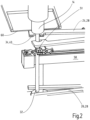
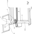
- Fig. 1 shows an apparatus according to the invention for carrying out a method according to the invention for producing at least one blow-molded, filled, and sealed container product 10, in particular made from at least one plastic.
- the apparatus comprises a stationary extrusion device 12 with a die head 14, a movable cutting device 16, a stationary molding tool 18 that can be opened and closed, and a movable gripper device 20 for transporting a preform 22, extruded by means of the die head 14 and cut to length by means of the cutting device 16, from the extrusion device 12 to the molding tool 18.
- the device has a support gas supply directed into the interior of the hose 32, which is not shown in the figures and which corresponds to the DE 102 45 318 A1 disclosed support gas supply.
- the device may comprise a calibration element 51 for section-by-section calibration of the outer diameter of the heat-soft tube 32 in the preforming position.
- the gripper device 20 has two grippers 24, 26, each extending in a horizontal plane and aligned parallel to one another so that they are arranged congruently one above the other.
- Each gripper 24, 26 has a pair of angled legs 28 that correspond to one another.
- the legs 28 of each gripper 24, 26 are arranged side by side and are hinged, mirror-inverted to one another, to the free ends of a U-shaped connecting plate 30 that extends vertically between the grippers 24, 26.
- the connecting plate 30 holds the tongs 24, 26 at such a distance from one another that a tube 32 extruded by means of the tube head 14 of the extrusion device 12 can be picked up at its two end regions by one tong 24, 26 each.
- each tong 24, 26 has a pair of gripping jaws 34, 36 at its end facing the forming tool 18.
- a slot 40 is made in each of the gripping jaws 34 of the first tongs 24, starting from their opposite inner sides, which slot is connected via a channel extending through the respective leg 28 to a vacuum pump (not shown in the figures) for the purpose of generating a negative pressure for circumferentially holding the hose 32 at its upper end region closest to the extrusion device 12 by suction of the hose 32 by means of the two gripping jaws 34 of the first tongs 24.
- the gripping jaws 36 of the second tongs 26 are designed without any recesses, so that when closed, they lie flat against one another, forming a clamping gap.
- a temperature control device (not shown in the figures) can be provided, which has a cooling circuit that cools the gripping jaws 34, 36 of a respective pair of tongs 24, 26 in order to prevent the hose 32 or preform 22 from accidentally sticking to the gripping jaws 34, 36 of the respective pair of tongs 24, 26.
- the respective pair of tongs 24, 26 can, as an alternative to the present embodiment, be designed as an angular gripper in the form of a parallel gripper (not shown).
- the first pair of tongs 24 can also be designed in several parts such that their gripping jaws 34 are interchangeable in order to adapt the receiving opening 38 of the first pair of tongs 24 to a predetermined hose diameter.
- the U-shaped connecting plate 30 is firmly connected on one side at its central region to a carriage 46, which can be moved on a rail 50 by means of a linear drive 48.
- the rail 50 is supported in its end regions by means of a foot part 52, 54 on a rectangular base plate 56 of the device and extends parallel to the base plate 56 in the longitudinal direction of the base plate 56 and the tongs 24, 26, which are also aligned parallel to the base plate 56.
- Both foot parts 52, 54 are each designed as L-shaped angles and are firmly connected to the rail 50 at a distance from one another on the side facing away from the hose head 14.
- a drive 58 of the linear drive 48 engages the end of the rail 50 that faces away from the hose head 14 of the extrusion device 12 and simultaneously projects beyond the base plate 56 in the longitudinal direction of the base plate 56, and from there extends vertically away from the rail 50 toward the base plate 56.
- a section-by-section calibration of the outer diameter of the heat-soft tube 32 can be carried out in the preforming position.
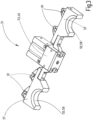
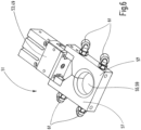
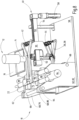
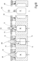
- a calibration element 51 ( Fig. 2 and 3 ) is provided which has a substantially rectangular base part 49 and two calibration jaws 57.
- the outer diameter of the hose section encompassed by the calibration jaws 57 of the closed calibration element 51 can be limited.
- the holder of the calibration element 51 is not shown in the figures.
- a calibration jaw 57 is articulated with one degree of freedom at each end region of the two side surfaces of the base part 49 extending in the longitudinal direction of the base part such that the calibration jaws 57 can be moved between an open position, in which they extend perpendicularly away from the side surfaces of the base part 49, and a closed position, in which the calibration jaws 57 extend away from the free end face of the base part 49 and are in contact with one another.
- the base part 49 has a drive 53 for moving the calibration jaws 57 from the open position to the closed position and vice versa.
- a semicircular recess 59 is each formed, which together form a circular receiving opening 55 for the hose 32 in the closed position of the calibration jaws 57.
- the diameter of the receiving opening 55 is adapted to the size of the neck of the container product 10 to be manufactured.
- the other side surface of the respective calibration jaw 57 is flat and preferably has two connections 61 for a temperature control device not shown in the figures.
- the temperature control device serves to cool the calibration jaws 57, so that the hose 32 can be locally cooled in a targeted manner and, if necessary, prevents undesired adhesion of the heat-resistant hose 32 to the calibration jaws 57.
- the gripper device 20 includes the cutting device 16 in the form of a cutting blade that is aligned parallel to the base plate 56 and whose cutting edge 60 can be moved back and forth between the hose head 14 and the gripper device 20 in the transverse direction to the rail 50 and the base plate 56.
- the cutting blade can, for example, be heated in the form of a so-called hot blade or oscillate at an ultrasonic frequency.
- Such configurations of the cutting blade 60 are known from the prior art, which is why the respective configuration will not be discussed in detail here.
- two stationary housing plates 62 are arranged, aligned parallel to one another, which, aligned longitudinally to the base plate 56, extend away from the base plate 56 in the direction of the hose head 14.
- an extension 64 extending away from the base plate 56 is provided at its edge region facing away from the drive 58 of the linear drive 48 and the base plate 56.
- a guide pin 66 extends between each of these housing plates 62 and is secured at both ends to each housing plate 62.
- each support plate 68 carries a holding jaw 70, a head jaw 72, and a forming jaw 74, which extend in pairs opposite one another from the mutually facing sides 76 of the support plates 68.
- the respective holding jaw 70 is in the central region the side 78 of the support plates 68 facing away from the base plate 56.
- a part-circular recess 80 for holding the preform 22 is provided in each of the mutually facing sides of the holding jaws 70.
- the respective holding jaw 70 is adjoined in the direction of the base plate 56 by first the head jaw 72 and then the mold jaw 74.
- a support plate drive 84 is fixed on the opposite sides 82 of the housing plates 62, which acts in a pushing or pulling manner on the support plate 68 adjacent to the respective housing plate 62, so that the support plates 68 can be moved towards one another by means of the support plate drive 84 to close the molding tool 18 and away from one another to open the molding tool 18.
- a head jaw drive 88 is fixed on each of the opposite sides 86 of the support plates 68, which acts in a pushing or pulling manner on the adjacent head jaw 72, so that the head jaws 72 can be moved toward and away from each other independently of the holding jaws 70 and forming jaws 74.
- the direction of travel of the support plates 68 is oriented transversely to the direction of travel of the gripper device 20.
- the two tongs 24, 26 can be moved simultaneously by means of the linear drive 48 from a preforming position, the receiving position of the extruded tube 32 by the tongs 24, 26, to a transfer position in which the preform 22 is transferred into the opened mold 18, and vice versa.
- cooling, heating, shielding, and/or reflection devices can be provided along its travel path, wherein the temperature of the tube 32 or of the preform 22 can be monitored by means of a temperature sensor.
- the respective cooling device can be designed such that it flows against the preform 22 using a cooling fluid, preferably gas, in particular air.
- a cooling fluid preferably gas, in particular air.
- the respective heating device can be designed as a radiant heating device, preferably with infrared radiation. By heating different areas of the tube 32, different wall thicknesses of the finished container product can be realized.
- the shielding and reflection devices (not shown) can each be designed as metal sheets.
- Sensors in particular optical sensors, not shown in the figures, can also be provided on the gripper device 20 or along the travel path of the preform 22 for checking the preform 22, for example with regard to its geometry, its dimensions, its transparency, its wall thickness distribution, its temperature (distribution), its degree of crystallinity, its weight, for impurities and/or for particle inclusions, wherein the measured values of the respective sensor can be incorporated into a corresponding control of the extrusion process.
- Protective devices not shown in the figures may be provided to protect the preform 22 during its transport.
- a protective device for protection against, in particular, microbial and/or particulate, contamination may be designed in such a way be that during the movement of the preform 22, the inner and/or outer surface 90 of the preform 22 is flowed onto by means of pure, sterile, i.e. low-particle and low-germ, and/or filtered air or inert gas.
- treatment devices can be provided along its travel path, which treat the inner and/or outer surfaces 90 of the preform 22 using a fluid.
- the treatment device can be configured such that it flows a fluid onto the preform 22.
- a reactive fluid for example a fluorine-containing gas, enables the targeted modification of the inner and/or outer surfaces 90 of the preform 22, which leads to an improvement in the barrier properties of the polymer used to produce the preform 22.
- Treating surface 90 with siloxane-containing gas mixtures such as hexamethyldisiloxane (HMDSO) or 1,1,1,3,3,3-hexamethyldisilazane (HMDS), results in inerting and altered wetting properties. It has been shown that the surface modifications occur at temperatures of the preforms 22 in the range of 150 to 250 degrees Celsius, depending on the polymer, without the need for additional measures typical for coatings, such as heating or plasma treatment.
- the tube 32 is extruded in the vertical extrusion direction (z-direction) by means of the tube head 14 of the conventional extrusion device 12, so that it is arranged in a preforming position ( Fig. 1 ).
- the pliers 24, 26 are open.
- the stationary calibration element 51 ( Fig. 2 , 5 ) is provided for a section-by-section calibration of the outer diameter of the heat-soft hose 32 in the preforming position, its calibration jaws 57, which are also open, are first closed and spaced apart from the hose 32 ( Fig. 7 ).
- the support gas pulse directed into the interior of the hose 32 causes the hose 32 to be applied to the two calibration jaws 57 of the calibration element 51 and thus determines the outer diameter of the heat-soft hose 32 in the contact area.
- the tongs are closed by means of the respective tong drive 42, 44 ( Fig. 4 , 7 ).
- the hose 32 is closed and held at its lower end by means of the lower tongs 26, while the closed upper tongs 24 only surround the heat-resistant hose 32 at its upper end by means of their gripping jaws 34, but do not fully touch it.
- Due to the support gas pulse or a further support gas pulse the hose 32 is now expanded in the area of the upper tongs 24, applied to the gripping jaws 34, and held at the slots 40 by negative pressure.
- the negative pressure is generated by a vacuum pump (not shown in the figures), which is connected by means of a channel (not shown) extending through the respective leg 28.
- the calibration jaws 57 of the calibration element 51 are opened by means of the pneumatic drive 53 after the hose 32 has rested against the gripping jaws 34 of the first pliers 24.
- a tool-related Shaping in two spatially and temporally separate steps: In a first step, the tube 32 is shaped by means of the calibration element 51 before it is separated in the preforming position, and in a second step after the preform 22 has been introduced into the actual mold 18 in the transfer position.
- the calibration element 51 makes it possible to cool the tube 32 in the contact area of the calibration jaws 57 cooled by the temperature control device, thus specifically stabilizing the shape of the tube 32.
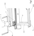
- the tube 32 is severed between the tube head 14 and the gripper device 20, forming an opening 92 at its upper end, whereby the preform 22 is cut to length from the tube 32.
- the preform 22 is transported by the gripper device 20, which holds the preform 22 in a one-sided open, vertical orientation, by means of the linear drive 48, starting from the preform position in a linear transport direction along the rail 50 of the linear drive 48 into the opened mold 18, in which the preform 22 is arranged in a main mold position ( Fig. 8 ).
- this movement is carried out first in the vertical direction (z-direction) downwards and then transversely to the stationary mold in the transfer position.
- the lower tongs 26 are opened and the support plates 68 are closed by means of the support plate drive 84, in particular the head jaws 72 are taken along by the support plates 68 and the holding jaws 70 and the forming jaws 74 are closed, so that the holding jaws 70 and the forming jaws 74 hold the preform 22 between them ( Fig. 9 ).
- the preform 22 is welded on its closed underside 94 by means of the forming jaws 74.
- opening the upper clamp 24 completes the transfer of the preform 22 from the gripper device 20 into the mold 18. Due to the essentially freely accessible arrangement of the preform 22 during the travel movement, it is accessible for further process steps.
- the container body 96 of the container product 10 is first blow molded by means of a blow molding device 98 ( Fig. 10 - Step 2).
- the container body 96 is filled with filling material via its opening 92 by means of a filling device 100 ( Fig. 10 - Step 3).
- a head part 102 of the filled container product 10 is formed, namely the head part 102 is closed to the outside ( Fig. 10 - Step 4).
- each head jaw 72 can be closed by means of a head jaw drive 88 in the form of a hydraulic cylinder and each mold jaw 74 can be closed by means of a support plate drive 84 in the form of another hydraulic cylinder, the blow molding and filling process can be carried out at a particularly high pressure.
- the gripper device 20 is then transported back along the rail 50 to the extrusion position and simultaneously opened for a renewed sequence of the preceding process steps. Finally, the mold 74, head 72, and holding jaws 70 ( Fig. 10 - Step 5) the finished container product 10 is removed from the mold 18, which can also be done with an additional manipulator, such as a robot arm.
- one of the mold jaws 74 stationary by fixing it to the base plate 56 and to move only the other mold jaw 74, thereby minimizing the number of support plate drives 84.
- Such a one-sided closing movement requires that the preform is always located in the center between the two mold jaws 74, which is made possible by an easily implemented transverse movement of the gripping device 20.
- the container product 10 can advantageously be removed upwards, which is possible according to the invention because the space above the mold is free, i.e. is not occupied by the hose head 14 of the extrusion device 12.
- the gripping device 20 and, with it, the preform 22 can initially be moved in the vertical direction (z-direction) after separation.
- This makes it possible to dispense with the technically complex tilting movement of the extruder, which is common in the prior art and results in a vertical movement of the extrusion head 14, while maintaining continuous extrusion of a tube 32.
- the preform 22 is moved downward in the extrusion direction (z-direction) with the aid of the gripping device 20 before transport transversely thereto to the main mold position begins.
- the gripping device 20 according to the invention has proven particularly advantageous for transporting lightweight preforms. While, for preforms 22 weighing more than approximately 0.1 kg, securing them during transport by only the upper tong 24 is often sufficient for stable production processes with low reject rates, securing them according to the invention by several tongs 24, 26 is advantageous for lightweight preforms 22 for the production of lightweight containers weighing less than approximately 0.06 kg, as well as for multiple die heads.
- the lightweight containers produced in this way - such as bottles or ampoules - can preferably be used for medical purposes, for example for infusion solutions, inhalants, ophthalmics, injectables or diagnostics and oral tonics.
Landscapes
- Engineering & Computer Science (AREA)
- Manufacturing & Machinery (AREA)
- Mechanical Engineering (AREA)
- Blow-Moulding Or Thermoforming Of Plastics Or The Like (AREA)
Claims (20)
- Procédé de fabrication d'au moins un produit (10) de récipient formé, rempli et fermé comprenant au moins les stades de procédé suivants :- extrusion d'un tuyau (32) souple au moyen d'un dispositif (12) d'extrusion en utilisant du gaz d'appui dans une direction d'extrusion verticale en une position de préformage ;- fermeture du tuyau (32) souple à son extrémité inférieure et séparation du même à son extrémité supérieure ouverte ;- transport de l'ébauche (22) ainsi tronçonnée au moyen d'un dispositif (20) de préhension dans une direction de transport linéaire transversalement à la direction d'extrusion de la position de préformage à un outil (18) de formage ouvert ;- transfert de l'ébauche (22) dans l'outil (18) de formage ouvert au moyen du dispositif (20) de préhension en une position de formage principale ;- fermeture de l'outil (18) de formage en vue de former davantage l'ébauche (22) par un gradient de pression ;- remplissage et fermeture de l'ébauche (22) ; et- retour du dispositif (20) de préhension à la position de préformage pour une succession renouvelée des stades de procédé précédents.
- Procédé suivant la revendication 1, caractérisé en ce que l'on ferme, dans la position de préformage, le tuyau (32) souple extrudé à son extrémité inférieure, par une pince inférieure du dispositif (20) de préhension.
- Procédé suivant la revendication 1 ou 2, caractérisé en ce que l'on met et maintient le tuyau (32) souple extrudé, après la fermeture à son extrémité inférieure, au moyen d'une pression de gaz d'appui sur une pince (24) supérieure du dispositif (20) de préhension au moyen d'une pression de gaz d'appui par une tête (14) pour tuyau souple du dispositif (12) d'extrusion.
- Procédé suivant l'une des revendications précédentes, caractérisé en ce que l'on sépare, entre la tête (14) pour tuyau souple et le dispositif (20) de préhension, l'ébauche (22) dans la position de préformage du tuyau (32) souple extrudé au moyen d'un dispositif (16) de coupe.
- Procédé suivant l'une des revendications précédentes, caractérisé en ce que, dans la position de préformage, on déplace le dispositif (20) de préhension avec l'ébauche (22) dans la direction verticale (direction z) vers le bas, mais on ne déplace pas la tête (14) pour le tuyau souple pendant l'extrusion continue du tuyau (32) souple.
- Procédé suivant l'une des revendications précédentes, caractérisé en ce que l'ébauche (22) est en au moins une polyoléfine partiellement cristalline ou amorphe, qui a un poids de moins de 0,1 kg, de préférence de moins de 0,07 kg, et une épaisseur moyenne de paroi de moins de 0,3 cm, de préférence de moins de 0,2 cm, et à l'instant de la séparation sa température moyenne est dans la plage de 150°C à 210°C.
- Procédé suivant l'une des revendications précédentes, caractérisé en ce que l'on maintient dans son orientation sensiblement verticale ouverte vers le haut l'ébauche (22) dans la position de préformage et pendant le transport au moyen du dispositif (20) de préhension.
- Procédé suivant l'une des revendications précédentes, caractérisé en ce que, pendant son transport de la position de préformage à la position de formage principale, on maintient l'ébauche (22) au moins de temps à autre en au moins deux points différents, de préférence en ses deux extrémités, au moyen de deux pinces (24, 26) du dispositif (20) de préhension.
- Procédé suivant l'une des revendications précédentes, caractérisé en ce que, outre le façonnage de l'ébauche (22) dans l'outil (18) de formage, a lieu, en la position de formage principale, au moins un autre façonnage, de préférence lié à l'outil, de l'ébauche (22) et/ou du tuyau (32) souple en dehors de la position de formage principale.
- Procédé suivant la revendication 9, caractérisé en ce que, un autre façonnage du tuyau (32) souple a lieu dans la position de préformage, par le fait que l'on applique au moins un tronçon du tuyau (32) souple à des mâchoires (57) de calibrage d'une unité (51) de calibrage, pour la limitation de son diamètre extérieur.
- Procédé suivant l'une des revendications précédentes, caractérisé en ce que l'on applique au moins une partie du tuyau (32) souple dans la position de préformage, au moyen d'une courte impulsion de gaz d'appui, à peu près en même temps aux mâchoires (57) de calibrage d'une unité (51) de calibrage et à la pince (24) supérieure du dispositif (20) de préhension.
- Procédé suivant l'une des revendications précédentes, caractérisé en ce que, ou bien l'outil (18) de formage prend en charge, au moyen de mâchoires (70) de maintien opposées l'une à l'autre par leur fermeture, l'ébauche (22) du dispositif (20) de préhension ; ou bien on maintient par la pince (24) supérieure du dispositif (20) de préhension l'ébauche (22) se trouvant au moins dans l'outil (18) de formage au moins jusqu'au début de son autre formage.
- Procédé suivant l'une des revendications précédentes, caractérisé en ce que l'on ferme l'outil (18) de formage autour de l'ébauche (22) par un mouvement d'un seul côté de seulement l'une des mâchoires (74) de formage, tandis que l'on immobilise de manière fixe l'autre mâchoire (74) de formage.
- Procédé suivant l'une des revendications précédentes, caractérisé en ce que l'on soumet à une mesure et/ou un contrôle l'ébauche (22) au moins de temps en temps pendant le transport entre la position de préformage et le transfert à l'outil (18) de formage, en particulier pour la détermination de ses dimensions et/ou de son poids et/ou de sa répartition de température et/ou de sa transparence et/ou de sa cristallinité et/ou d'éventuelles impuretés.
- Procédé suivant l'une des revendications précédentes, caractérisé en ce que le produit (10) de récipient rempli est un récipient à des fins médicales, en particulier un récipient de poids léger d'un volume de moins de 2 litres et/ou d'un poids à vide de moins de 0,06 kilo.
- Installation pour effectuer un procédé suivant l'une des revendications précédentes, comprenant au moins les composants suivants :- dispositif (12) d'extrusion pour l'extrusion d'un tuyau (32) souple ;- dispositif à gaz d'appui ;- dispositif de fermeture pour la fermeture du tuyau souple à son extrémité inférieure et séparation du même à son extrémité supérieure ouverte ;- dispositif de transport pour le transport de l'ébauche (22) tronçonnée au moyen d'un dispositif (20) de préhension dans une direction de transport linéaire transversalement à la direction d'extrusion de la position de préformage à un outil (18) de formage ouvert ;- outil (18) de formage ;- dispositif de remplissage et dispositif de fermeture pour remplir et fermer l'ébauche.
- Installation suivant la revendication 16, caractérisée en ce que le dispositif (20) de préhension comprend au moins deux paires (24, 26) de pinces à distance axialement l'une de l'autre, qui reçoivent entre elles au moins une ébauche (22), dans laquelle la paire (24) supérieure de pinces laisse libre une ouverture (38) de réception de l'extrémité (92) supérieure ouverte de l'ébauche (22) et la paire (26) inférieure de pinces rend possible une fermeture du tuyau (32) souple et un maintien du côté de l'extrémité dans le dispositif (20) de préhension.
- Installation suivant la revendication 17, caractérisée en ce que les deux paires (24, 26) de pinces sont guidées conjointement d'une position de préformage à une position de transfert à un outil (18) de formage et peuvent être déplacées en retour, de préférence au moyen d'un entraînement (48) linéaire.
- Installation suivant l'une des revendications 16 à 18, caractérisée en ce que l'outil (18) de formage, de préférence mobile seulement d'un côté, est constitué d'au moins une paire de mâchoires de formage (74) et de tête (72) et n'a pas, de préférence, de mâchoires (70) de maintien.
- Installation suivant l'une des revendications 16 à 19, caractérisée en ce que le dispositif (12) d'extrusion a une tête (14) pour tuyau souple, qui outre la production d'un tuyau (32) souple en matière plastique extrudée forme celui-ci également au moyen d'un gaz d'apport, de préférence d'air d'apport et/ou l'applique à des surfaces comme la une pince (24) et/ou des mâchoires (57) de calibrage.
Applications Claiming Priority (2)
| Application Number | Priority Date | Filing Date | Title |
|---|---|---|---|
| DE102020002077.1A DE102020002077A1 (de) | 2020-04-01 | 2020-04-01 | Verfahren zum Herstellen eines Behältererzeugnisses und Vorrichtung zur Durchfühung des Verfahrens |
| PCT/EP2021/055052 WO2021197737A1 (fr) | 2020-04-01 | 2021-03-01 | Procédé de production d'un produit de contenant, et dispositif de mise en œuvre du procédé |
Publications (3)
| Publication Number | Publication Date |
|---|---|
| EP4100229A1 EP4100229A1 (fr) | 2022-12-14 |
| EP4100229C0 EP4100229C0 (fr) | 2025-05-14 |
| EP4100229B1 true EP4100229B1 (fr) | 2025-05-14 |
Family
ID=74853644
Family Applications (1)
| Application Number | Title | Priority Date | Filing Date |
|---|---|---|---|
| EP21709386.3A Active EP4100229B1 (fr) | 2020-04-01 | 2021-03-01 | Procédé de production d'un produit de contenant, et dispositif de mise en oeuvre du procédé |
Country Status (5)
| Country | Link |
|---|---|
| US (1) | US20230145486A1 (fr) |
| EP (1) | EP4100229B1 (fr) |
| CN (1) | CN115605336A (fr) |
| DE (1) | DE102020002077A1 (fr) |
| WO (1) | WO2021197737A1 (fr) |
Families Citing this family (6)
| Publication number | Priority date | Publication date | Assignee | Title |
|---|---|---|---|---|
| DE102021003226A1 (de) | 2021-06-23 | 2022-12-29 | Kocher-Plastik Maschinenbau Gmbh | Vorrichtung |
| DE102021005495A1 (de) | 2021-11-06 | 2023-05-11 | Kocher-Plastik Maschinenbau Gmbh | Trennvorrichtung |
| DE102021005494A1 (de) | 2021-11-06 | 2023-05-11 | Kocher-Plastik Maschinenbau Gmbh | Trennvorrichtung |
| DE102023001403B3 (de) | 2023-04-11 | 2023-12-14 | Kocher-Plastik Maschinenbau Gmbh | Vorrichtung nebst zugehöriger Formwerkzeuge und System bestehend aus einem Satz von Formwerkzeugen |
| DE102024001609A1 (de) * | 2024-05-17 | 2025-11-20 | Rommelag Engineering Gmbh | Vorrichtung |
| DE102024001610A1 (de) | 2024-05-17 | 2025-12-04 | Rommelag Engineering Gmbh | Vorrichtung und Verfahren |
Citations (3)
| Publication number | Priority date | Publication date | Assignee | Title |
|---|---|---|---|---|
| DE1163000B (de) * | 1961-08-18 | 1964-02-13 | Armaturenfabrik Johann Fischer | Vorrichtung zum Herstellen von Hohlkoerpern, insbesondere Flaschen aus thermoplastischen Kunststoffen |
| US4153408A (en) * | 1976-05-25 | 1979-05-08 | Hoechst Aktiengesellschaft | Process for extrusion blowing of thermoplastic hollow articles and gripper device for drawing the parison into the blow mold |
| DE3231859A1 (de) * | 1981-08-26 | 1983-04-07 | Automatic Liquid Packaging, Inc., 60005 Arlington Heights, Ill. | Behaelter aus thermoplastischem material sowie verfahren und einrichtung zur herstellung desselben |
Family Cites Families (17)
| Publication number | Priority date | Publication date | Assignee | Title |
|---|---|---|---|---|
| US2783503A (en) * | 1953-09-21 | 1957-03-05 | Owens Illinois Glass Co | Method of forming hollow plastic articles |
| DE1404996A1 (de) * | 1960-04-11 | 1969-05-08 | Fischer Maschf Johann | Verfahren und Vorrichtung zum Herstellen von Hohlkoerpern,wie Flaschen,Tuben u.dgl. aus warmformbaren Werkstoffen,insbesondere Kunststoffen |
| DE1779384A1 (de) * | 1968-08-05 | 1971-11-18 | Conduco Ag | Verfahren und Vorrichtung zur Herstellung von mit einer halsfoermigen OEffnung versehenen Hohlkoerpern aus thermoplastischem Kunststoff im Blasverfahren |
| IT1025255B (it) * | 1973-11-03 | 1978-08-10 | Mehnert G | Procedimento e dispositivo per lostampaggio dell apertura in forma di collo di un corpo cavo realizza to in materiale termoplastico con il metodo di soffiatura e relativo allontanamento delle porzioni di sfrido risultanti |
| US4699748A (en) * | 1982-08-03 | 1987-10-13 | Automatic Liquid Packaging, Inc. | Container with insert having a fully or partially encapsulating seal with a frangible web formed against said insert |
| SK287002B6 (sk) * | 2000-02-22 | 2009-09-07 | Soplar Sa | Zariadenie na výrobu dutých telies a spôsob ich výroby |
| DE10063282C2 (de) | 2000-12-19 | 2003-06-18 | Bernd Hansen | Verfahren und Vorrichtung zum Herstellen und Befüllen von Behältern |
| DE10063795A1 (de) * | 2000-12-21 | 2002-06-27 | Krones Ag | Vorrichtung und Verfahren zur Herstellung von Behältern durch Blasformung |
| DE10245318A1 (de) | 2002-09-27 | 2004-04-08 | Hansen, Bernd, Dipl.-Ing. | Formverfahren, insbesondere Blas- und/oder Vakuumformverfahren, zum Herstellen eines mit einem abzugebenden Medium gefüllten Abgabebehälters |
| US6923637B2 (en) * | 2003-04-25 | 2005-08-02 | Bekum Maschinenfabriken Gmbh | Blow molding machine |
| DE10347908A1 (de) | 2003-10-15 | 2005-05-19 | Bernd Hansen | Verfahren und Vorrichtung zur Herstellung mindestens eines mit einem Medium befüllten Behälters |
| JP4172713B2 (ja) * | 2004-12-09 | 2008-10-29 | 福田金型株式会社 | 樹脂成形におけるプリフォームの成形装置 |
| DE102007028882B4 (de) * | 2007-06-20 | 2015-04-23 | Kautex Textron Gmbh & Co. Kg | Extrusionsblasformmaschine sowie Verfahren zur Herstellung eines Kunststoffhohlkörpers |
| DE102008030318A1 (de) * | 2008-06-30 | 2009-12-31 | Ti Automotive Technology Center Gmbh | Verfahren zur Herstellung eines Kunststoffbehälters |
| DE102014008611A1 (de) | 2014-06-06 | 2015-12-17 | Kocher-Plastik Maschinenbau Gmbh | Behältnis |
| DE102014008610A1 (de) * | 2014-06-06 | 2015-12-17 | Kocher-Plastik Maschinenbau Gmbh | Abgabevorrichtung |
| WO2016021435A1 (fr) * | 2014-08-04 | 2016-02-11 | 東洋製罐株式会社 | Dispositif et procédé d'apport de paraison et machine et procédé de moulage par soufflage utilisant ceux-ci |
-
2020
- 2020-04-01 DE DE102020002077.1A patent/DE102020002077A1/de active Pending
-
2021
- 2021-03-01 EP EP21709386.3A patent/EP4100229B1/fr active Active
- 2021-03-01 WO PCT/EP2021/055052 patent/WO2021197737A1/fr not_active Ceased
- 2021-03-01 US US17/915,629 patent/US20230145486A1/en active Pending
- 2021-03-01 CN CN202180035627.9A patent/CN115605336A/zh active Pending
Patent Citations (3)
| Publication number | Priority date | Publication date | Assignee | Title |
|---|---|---|---|---|
| DE1163000B (de) * | 1961-08-18 | 1964-02-13 | Armaturenfabrik Johann Fischer | Vorrichtung zum Herstellen von Hohlkoerpern, insbesondere Flaschen aus thermoplastischen Kunststoffen |
| US4153408A (en) * | 1976-05-25 | 1979-05-08 | Hoechst Aktiengesellschaft | Process for extrusion blowing of thermoplastic hollow articles and gripper device for drawing the parison into the blow mold |
| DE3231859A1 (de) * | 1981-08-26 | 1983-04-07 | Automatic Liquid Packaging, Inc., 60005 Arlington Heights, Ill. | Behaelter aus thermoplastischem material sowie verfahren und einrichtung zur herstellung desselben |
Also Published As
| Publication number | Publication date |
|---|---|
| EP4100229C0 (fr) | 2025-05-14 |
| US20230145486A1 (en) | 2023-05-11 |
| CN115605336A (zh) | 2023-01-13 |
| EP4100229A1 (fr) | 2022-12-14 |
| DE102020002077A1 (de) | 2021-10-07 |
| WO2021197737A1 (fr) | 2021-10-07 |
Similar Documents
| Publication | Publication Date | Title |
|---|---|---|
| EP4100229B1 (fr) | Procédé de production d'un produit de contenant, et dispositif de mise en oeuvre du procédé | |
| EP2167302B1 (fr) | Procédé de fabrication de corps creux en matière synthétique thermoplastique, dispositif associé et récipient en matière synthétique ainsi fabriqué | |
| DE60314777T2 (de) | Doppelfolien thermoformung von kraftstofftanks | |
| DE69927151T2 (de) | Verfahren und vorrichtung zum herstellen steriler verpackungsbehälter | |
| DE69311663T2 (de) | Verfahren und Vorrichtung zum Herstellen von wärmebeständigen Behälten | |
| EP2588294B1 (fr) | Procédé pour produire un article en matière plastique et outil de soufflage pour la mise en oeuvre de ce procédé | |
| EP0041073B1 (fr) | Procédé et dispositif pour façonner des corps creux thermoplastiques à molécules orientés | |
| EP4313540B1 (fr) | Appareil et procédé de production de produits de réceptacle moulés, remplis et étanches en matière plastique | |
| DE102010050136A1 (de) | Anlage zum Verschweißen von Folien mit einem Einsetzstück zu einem Beutel, hiermit hergestelltes Produkt und Verfahren zum Verschweißen von Folie mit einem Einsetzstück zu einem Beutel | |
| JP2000318023A (ja) | パリソン取扱装置 | |
| EP3212381A1 (fr) | Dispositif et procede pour produire des sachets en plastique | |
| DE102010025006A1 (de) | Verfahren zur Herstellung von Hohlkörpern aus thermoplastischem Kunststoff sowie Vorrichtung zur Durchführung des Verfahrens | |
| DE2532413C2 (de) | Vorrichtung zum Blasformen von Hohlkörpern aus thermoplastischem Kunststoff | |
| EP0595158B1 (fr) | Procédé et dispositif de fabrication de corps creux en matière thermoplastique | |
| DE69104575T2 (de) | Siegeln von im Blasverfahren erzeugten Flaschen. | |
| WO2019158738A1 (fr) | Dispositif de retenue destiné à retenir des panneaux de matériau composite | |
| EP2155468B1 (fr) | Machine de moulage-soufflage par extrusion et procédé de fabrication d'un corps creux en matière plastique | |
| DE60100998T2 (de) | Verfahren und vorrichtung zum extrusionsformen von hohlkörpern aus kunststoff | |
| EP1737648B2 (fr) | Dispositif et procede pour la production de sacs plastiques munis d'elements de fermeture | |
| WO2020216564A1 (fr) | Procédé et dispositif de dépliage au moins partiel d'enveloppes d'emballage pliées à plat | |
| DE102013203085A1 (de) | Blasformverfahren | |
| DE19922684C2 (de) | Blasformmaschine für das abfallarme Blasen | |
| DE102022118938A1 (de) | Vorrichtung | |
| WO2024170073A1 (fr) | Appareil | |
| US7300273B2 (en) | System for forming a hollow body |
Legal Events
| Date | Code | Title | Description |
|---|---|---|---|
| STAA | Information on the status of an ep patent application or granted ep patent |
Free format text: STATUS: UNKNOWN |
|
| STAA | Information on the status of an ep patent application or granted ep patent |
Free format text: STATUS: THE INTERNATIONAL PUBLICATION HAS BEEN MADE |
|
| PUAI | Public reference made under article 153(3) epc to a published international application that has entered the european phase |
Free format text: ORIGINAL CODE: 0009012 |
|
| STAA | Information on the status of an ep patent application or granted ep patent |
Free format text: STATUS: REQUEST FOR EXAMINATION WAS MADE |
|
| 17P | Request for examination filed |
Effective date: 20220909 |
|
| AK | Designated contracting states |
Kind code of ref document: A1 Designated state(s): AL AT BE BG CH CY CZ DE DK EE ES FI FR GB GR HR HU IE IS IT LI LT LU LV MC MK MT NL NO PL PT RO RS SE SI SK SM TR |
|
| DAV | Request for validation of the european patent (deleted) | ||
| DAX | Request for extension of the european patent (deleted) | ||
| GRAP | Despatch of communication of intention to grant a patent |
Free format text: ORIGINAL CODE: EPIDOSNIGR1 |
|
| STAA | Information on the status of an ep patent application or granted ep patent |
Free format text: STATUS: GRANT OF PATENT IS INTENDED |
|
| INTG | Intention to grant announced |
Effective date: 20250218 |
|
| GRAS | Grant fee paid |
Free format text: ORIGINAL CODE: EPIDOSNIGR3 |
|
| GRAA | (expected) grant |
Free format text: ORIGINAL CODE: 0009210 |
|
| STAA | Information on the status of an ep patent application or granted ep patent |
Free format text: STATUS: THE PATENT HAS BEEN GRANTED |
|
| AK | Designated contracting states |
Kind code of ref document: B1 Designated state(s): AL AT BE BG CH CY CZ DE DK EE ES FI FR GB GR HR HU IE IS IT LI LT LU LV MC MK MT NL NO PL PT RO RS SE SI SK SM TR |
|
| REG | Reference to a national code |
Ref country code: GB Ref legal event code: FG4D Free format text: NOT ENGLISH |
|
| REG | Reference to a national code |
Ref country code: CH Ref legal event code: EP |
|
| REG | Reference to a national code |
Ref country code: IE Ref legal event code: FG4D Free format text: LANGUAGE OF EP DOCUMENT: GERMAN |
|
| U01 | Request for unitary effect filed |
Effective date: 20250514 |
|
| U07 | Unitary effect registered |
Designated state(s): AT BE BG DE DK EE FI FR IT LT LU LV MT NL PT RO SE SI Effective date: 20250520 |
|
| RAP4 | Party data changed (patent owner data changed or rights of a patent transferred) |
Owner name: ROMMELAG ENGINEERING GMBH |
|
| U1H | Name or address of the proprietor changed after the registration of the unitary effect |
Owner name: ROMMELAG ENGINEERING GMBH; DE |
|
| PG25 | Lapsed in a contracting state [announced via postgrant information from national office to epo] |
Ref country code: ES Free format text: LAPSE BECAUSE OF FAILURE TO SUBMIT A TRANSLATION OF THE DESCRIPTION OR TO PAY THE FEE WITHIN THE PRESCRIBED TIME-LIMIT Effective date: 20250514 |
|
| PG25 | Lapsed in a contracting state [announced via postgrant information from national office to epo] |
Ref country code: NO Free format text: LAPSE BECAUSE OF FAILURE TO SUBMIT A TRANSLATION OF THE DESCRIPTION OR TO PAY THE FEE WITHIN THE PRESCRIBED TIME-LIMIT Effective date: 20250814 Ref country code: GR Free format text: LAPSE BECAUSE OF FAILURE TO SUBMIT A TRANSLATION OF THE DESCRIPTION OR TO PAY THE FEE WITHIN THE PRESCRIBED TIME-LIMIT Effective date: 20250815 |
|
| PG25 | Lapsed in a contracting state [announced via postgrant information from national office to epo] |
Ref country code: PL Free format text: LAPSE BECAUSE OF FAILURE TO SUBMIT A TRANSLATION OF THE DESCRIPTION OR TO PAY THE FEE WITHIN THE PRESCRIBED TIME-LIMIT Effective date: 20250514 |
|
| PG25 | Lapsed in a contracting state [announced via postgrant information from national office to epo] |
Ref country code: HR Free format text: LAPSE BECAUSE OF FAILURE TO SUBMIT A TRANSLATION OF THE DESCRIPTION OR TO PAY THE FEE WITHIN THE PRESCRIBED TIME-LIMIT Effective date: 20250514 |
|
| PG25 | Lapsed in a contracting state [announced via postgrant information from national office to epo] |
Ref country code: RS Free format text: LAPSE BECAUSE OF FAILURE TO SUBMIT A TRANSLATION OF THE DESCRIPTION OR TO PAY THE FEE WITHIN THE PRESCRIBED TIME-LIMIT Effective date: 20250814 |
|
| PG25 | Lapsed in a contracting state [announced via postgrant information from national office to epo] |
Ref country code: IS Free format text: LAPSE BECAUSE OF FAILURE TO SUBMIT A TRANSLATION OF THE DESCRIPTION OR TO PAY THE FEE WITHIN THE PRESCRIBED TIME-LIMIT Effective date: 20250914 |