EP4100218B1 - Effecteur terminal, robot, système et procédé pour manipuler des objets dans un isolateur - Google Patents
Effecteur terminal, robot, système et procédé pour manipuler des objets dans un isolateur Download PDFInfo
- Publication number
- EP4100218B1 EP4100218B1 EP21703244.0A EP21703244A EP4100218B1 EP 4100218 B1 EP4100218 B1 EP 4100218B1 EP 21703244 A EP21703244 A EP 21703244A EP 4100218 B1 EP4100218 B1 EP 4100218B1
- Authority
- EP
- European Patent Office
- Prior art keywords
- receptacle
- end effector
- gripping
- displacement
- isolator
- Prior art date
- Legal status (The legal status is an assumption and is not a legal conclusion. Google has not performed a legal analysis and makes no representation as to the accuracy of the status listed.)
- Active
Links
Images
Classifications
-
- B—PERFORMING OPERATIONS; TRANSPORTING
- B25—HAND TOOLS; PORTABLE POWER-DRIVEN TOOLS; MANIPULATORS
- B25J—MANIPULATORS; CHAMBERS PROVIDED WITH MANIPULATION DEVICES
- B25J15/00—Gripping heads and other end effectors
- B25J15/0052—Gripping heads and other end effectors multiple gripper units or multiple end effectors
Definitions
- the present invention relates to an end effector, a robot, a system and a method for handling objects in an isolator.
- end effectors can be used to handle different objects, which are suitable for handling the respective object type.
- end effectors are also known that are suitable for handling different object types. These end effectors have, for example, several tools or a multi-function tool for handling the different object types.
- a filling arm is disposed within a chamber.
- An optical sensor is configured to detect openings of the containers within the chamber. The positions of the detected openings are used to guide the filling arm to fill the containers with a product.
- the publication shows EP 2 733 196 A1 a liquid processing system for processing liquid biological material.
- the liquid processing system comprises: a body provided to rotate about an axis within a predetermined working space; a first arm provided on the body and having three degrees of freedom or higher; a second arm provided on the body and having three degrees of freedom or higher; driving means configured to drive each of the body, the first arm, and the second arm; physiochemical equipment arranged within the working space and within the movement range of at least one of the first arm and the second arm; wherein the driving means is operated by teaching based on the positions and shapes of the physiochemical equipment, and the biological material is processed using the physiochemical equipment.
- the publication shows US 7 789 443 B2 a gripper for use with a robot.
- the gripper includes a support body for releasably attaching the gripper to a movable arm and a workpiece contact body having a groove extending along at least a portion of the contact body for engaging a curved outer edge of the workpiece.
- a coupling member connects the support body to the workpiece contact member and has a flexure component that flexes to allow radial and/or tangential relative movement of the workpiece contact body with respect to the support body to reduce slippage between the workpiece and the contact body when the gripper engages the workpiece.
- the publication shows US 8 857 875 B2 a robot comprising a robot arm.
- a robot hand is arranged at a distal end of the robot arm and grasps an object.
- the robot hand includes an air chuck that includes a pair of pistons and an air cylinder.
- the air cylinder opens and closes the pistons parallel to each other.
- a pair of first gripping elements are disposed on a first side of the pistons and move close to and away from each other within a first movable range on a movable plane.
- a pair of second gripping elements are disposed on a second side of the pistons and move close to and away from each other within a second movable range that is different from the first movable range on the movable plane.
- the robot hand pivots relative to the distal end of the robot arm about a pivot axis that is approximately perpendicular to the movable plane.
- an object of the present invention to provide an end effector for handling objects in an isolator, which has the simplest possible structure and is as easy to control and manufacture as possible.
- an end effector for handling objects in an isolator comprises a first receptacle for a first object, a second receptacle for a second object, and a first displacement element, wherein the receptacles are arranged in a longitudinal direction on opposite sides of the end effector, wherein each receptacle can be moved between a receiving position in which the respective object can be received in the corresponding receptacle, and a gripping position in which the respective object can be gripped with the corresponding receptacle can be gripped, wherein each receptacle has a first gripping section, wherein the first gripping section of the first receptacle is arranged at a first end of the displacement element and the first gripping section of the second receptacle is arranged at an opposite, second end of the displacement element, wherein the displacement element is displaceable such that the first receptacle and the second receptacle can each
- the end effector has two first receptacles and two displacement elements, wherein the first gripping section of one of the first receptacles is arranged at the first end of each displacement element, wherein the first and second gripping sections of the second receptacle are arranged at the second, opposite ends of the displacement elements.
- a robot for handling objects in an isolator comprising an end effector according to the first aspect of the invention.
- a system comprising an isolator and a robot according to the second aspect of the invention arranged in the isolator.
- the objects to be handled can be, for example, vials, cartridges, bottles, syringes, cylinder ampoules, filling needles, a filling needle holder, Petri dishes, agar plates and/or the like.
- the first object is preferably a vial, a bottle, a syringe, a cylinder ampoules, filling needles or a filling needle holder, in particular a tangible projection of a filling needle holder.
- the second object is preferably a Petri dish or an agar plate.
- the term "isolator” generally refers to a container that is hermetically and gas-tightly sealed from the surrounding work area. A defined atmosphere can be created within an isolator for processing sensitive or dangerous products.
- the isolator can preferably be an aseptic isolator, which preferably has a filling area for filling objects (e.g. vials, cartridges, bottles, syringes and/or the like) with fluid using filling needles.
- Each holder has a holding position and a gripping position and can be moved between these positions.
- each holder In the holding position, each holder is opened wide enough for the holder to hold a corresponding object. In other words, the holder is opened wide enough for the corresponding object to be inserted into the holder.
- the holding position can therefore also be used as an open or open position.
- the gripping position In the gripping position, the holder is closed so far that the corresponding object is gripped by the holder. "Gripping" here means that the object is clamped or held in the holder.
- the gripping position can therefore also be referred to as the closed position.
- the first displacement element is displaceable. This means that the first displacement element is movable relative to other components of the end effector. In other words, the first displacement element is arranged displaceably on the end effector.
- the first displacement element couples the displacement of the first and second receptacles.
- the first displacement element extends from the first receptacle to the second receptacle and forms the corresponding first gripping sections of the receptacles at its ends. If the first displacement element is displaced, the gripping sections at the ends of the first displacement element are also displaced so that the receptacles are either opened further or closed further. This also displaces the receptacles between the gripping position and the receptacle position.
- the end effector is thus designed as a multifunctional tool that has two holders with which different objects can be handled. By moving the displacement element, both holders can be moved simultaneously. This means that only one drive means is required for the displacement element to move both holders.
- the end effector has two first receptacles and two displacement elements, wherein the first gripping section of one of the first receptacles is arranged at the first end of each displacement element, wherein the first and second gripping sections of the second receptacle are arranged at the second, opposite ends of the displacement elements.
- two first objects can be gripped simultaneously with the first receptacles.
- the second holder is preferably designed for handling larger objects, such as Petri dishes or agar plates, which are usually handled individually.
- the robot is designed to move and align the end effector in the isolator.
- a first object to be handled can be arranged in the isolator.
- the first receptacle can be moved or arranged in the receiving position.
- the robot can then move the end effector in the isolator to the position of the object.
- the end effector can be moved so that the first object is received in the first receptacle.
- the first receptacle can be moved to the gripping position in order to grip the object.
- the robot can then move the end effector further in the isolator, whereby the first object gripped in the first receptacle can be transferred in space.
- the first receptacle is moved back to the receiving position.
- the second object can also be picked up, gripped, transferred and released again in a similar way in the second receptacle.
- the end effector according to the invention thus makes it possible to handle various objects within an isolator in the simplest possible way.
- the end effector according to the invention has a simple structure and is easy to control and manufacture.
- the displacement element is displaceable such that, when the first receptacle is arranged in the receiving position, the second receptacle is arranged in the gripping position and, when the second receptacle is arranged in the receiving position, the first receptacle is arranged in the gripping position.
- the first holder and the second holder are shifted alternately between the pick-up position and the gripping position.
- the shifting element shifted in such a way that when shifted, one receptacle opens further while the other receptacle closes further.
- the displacement element is displaceable such that, when the first receptacle is arranged in the receiving position, the second receptacle is arranged in the receiving position and, when the second receptacle is arranged in the gripping position, the first receptacle is arranged in the gripping position.
- the first holder and the second holder are moved together between the holding position and the gripping position. To do this, the displacement element is moved in such a way that both holders are either opened further or closed further during the movement.
- each receptacle has a second gripping portion, wherein the first and the second gripping portion are arranged opposite one another in a transverse direction.
- the first and second gripping sections thus form two sides of the holder, between which the corresponding object is gripped or clamped in the gripping position.
- the longitudinal direction can in particular be arranged essentially perpendicular to the transverse direction.
- the distance between the first and the second gripping section in the receiving position is so large that the corresponding object can be picked up between the gripping sections.
- the corresponding object can be inserted into the holder in the holder position or removed or led out of the holder.
- the distance between the first and the second gripping section in the gripping position is so small that the corresponding object can be gripped between the gripping sections.
- the corresponding object is gripped in the gripping position by moving the gripping sections towards each other until they rest against the object and clamp or hold it between them.
- the displacement element can be displaced translationally or rotationally.
- Translational means that the displacement element can be moved relative to the other components of the end effector.
- translational displacement means that the displacement element is moved in space without changing its orientation in space.
- Rotational means that the displacement element is rotated relative to the other components of the end effector.
- rotational displacement means that the displacement element is rotated in space about an axis so that its orientation changes with respect to the other components of the end effector.
- the displacement element is displaceable in the transverse direction.
- each receptacle can be displaced either into the receiving position or into the gripping position.
- the displacement element is mounted so as to be rotatable about a first axis of rotation, wherein the first axis of rotation is perpendicular to the longitudinal direction and the transverse direction.
- the first axis of rotation can in particular be arranged between the first and second ends.
- each receptacle is either opened further or closed further. In other words, by rotating the displacement element about the first axis of rotation, each receptacle can be displaced either into the receiving position or into the gripping position.
- the end effector further comprises a bearing element for at least one of the receptacles, wherein the second gripping portion of the respective receptacle is arranged at one end of the bearing element.
- bearing element and the displacement element are thus on opposite sides in the transverse direction.
- a corresponding bearing element can be provided for each receptacle, which forms the corresponding second gripping section.
- the displacement element and the bearing element each have a recess at the corresponding ends, wherein the recesses form the corresponding gripping sections.
- the respective object In the gripping position, the respective object partially protrudes into the recess.
- the distance between the gripping sections at the opening of the holder is therefore smaller than the diameter of the object. This prevents the object from coming out of the holder in the gripping position.
- the object rests on at least two points on each gripping section designed as a recess. The recesses thus enable the object to self-center and hold securely on the gripping sections.
- the bearing element is arranged rigidly or movably on the end effector.
- the bearing element In order to arrange the bearing element rigidly on the end effector, the bearing element can be fixedly attached to the end effector. In order to arrange the bearing element movably on the end effector, the bearing element can either be displaceable in the transverse direction or can be mounted so as to be rotatable about a second axis of rotation, wherein the second axis of rotation is arranged parallel to the first axis of rotation.
- the bearing element is displaceable, in particular translationally or rotationally, wherein a movement of the bearing element is coupled with the movement of the displacement element, so that when displacing from the receiving position to the gripping position, the gripping sections are moved towards one another and when displacing from the gripping position to the receiving position, the gripping sections are moved away from one another.
- the gripping sections of a holder can be moved towards or away from each other. This allows the objects to be gripped particularly well and then released again.
- the end effector further comprises a drive device for displacing the displacement element.
- the displacement element can be displaced automatically using the drive device.
- the drive device can be controlled, for example, via a control device.
- the control device can, for example, transmit control signals to the drive device.
- the drive device is designed to displace the displacement element in the transverse direction or to rotate the displacement element about the first axis of rotation.
- the drive device can move the displacement element in the transverse direction. If the If the displacement element is rotationally displaceable, the drive device can rotate the displacement element about the corresponding first axis of rotation. This displaces each holder between the receiving position and the gripping position.
- the displacement element is mounted on the end effector by means of a first coupling element so as to be rotatable about the first axis of rotation, wherein the first coupling element has a toothed section, wherein the drive device has a drive shaft which is in engagement with the toothed section.
- the drive device can displace the displacement element in a rotational manner.
- the first coupling element is connected to the displacement element in a rotationally fixed manner, so that the first coupling element and the displacement element rotate together about the first axis of rotation.
- the drive shaft is rotated about a longitudinal axis, the first coupling element and the displacement element are rotated about the first axis of rotation.
- the drive shaft has a longitudinal axis.
- the longitudinal axis can, for example, be arranged parallel or perpendicular to the first axis of rotation.
- the first toothed section can have teeth that are distributed in a circumferential direction around the first axis of rotation, wherein the drive shaft has a thread that engages with the teeth of the first toothed section.
- the longitudinal axis of the drive shaft is arranged perpendicular to the first axis of rotation.
- the longitudinal axis of the drive shaft can be arranged parallel to the longitudinal direction.
- the bearing element is rotatably mounted on the end effector about the second axis of rotation by means of a second coupling element, wherein the second coupling element has a second toothing section, wherein the drive shaft is in engagement with the second toothing region.
- the drive device can displace the bearing element rotationally.
- the second coupling element is connected to the bearing element in a rotationally fixed manner, so that the second coupling element and the bearing element rotate together about the second axis of rotation.
- the second coupling element and the bearing element are rotated about the second axis of rotation. Since the first coupling element and the second coupling element are in engagement with the drive shaft, when the drive shaft rotates, both the first coupling element and the second coupling element are rotated about the first and second axes of rotation, respectively.
- the rotational movements of the displacement element and the bearing element are coupled to one another.
- the drive shaft is arranged between the first and the second coupling element.
- the first coupling element and the second coupling element are rotated in opposite directions of rotation, so that the gripping sections of a receptacle, the second gripping section of which has the bearing element, are moved towards or away from one another.
- the second toothed section may have teeth distributed in a circumferential direction around the second axis of rotation, wherein the thread of the drive shaft engages with the teeth of the second toothed section.
- the end effector has a bearing element for each first receptacle, wherein the second gripping section of the respective receptacle is arranged at one end of the corresponding bearing element.
- the bearing elements can again be designed to be movable, wherein a movement of each bearing element is coupled with the movement of the corresponding displacement element, so that when each receptacle is displaced, the gripping sections are moved towards or away from each other.
- the end effector has a drive device for displacing one of the displacement elements.
- Each drive device thus displaces a corresponding displacement element in a translational or rotational manner.
- three holders can be displaced simultaneously between a receiving position and a gripping position using two drive devices.
- the end effector has at least one spring element which is arranged such that it preloads the first receptacle and/or the second receptacle into the gripping position.
- At least one holder can be pre-tensioned into the gripping position.
- the holder pre-tensioned into the gripping position can then be moved into the holding position against the pre-tension acting through the spring element in order to hold an object in it.
- the holder In the event of a power failure while an object is being gripped and handled in this holder, the holder remains in the gripping position due to the pre-tension of the spring element. This prevents the holder from opening in the event of a power failure and the object to be handled from falling out of the holder.
- the robot has a support structure, in particular an articulated one, for carrying the end effector.
- the support structure can, for example, have several arms that are coupled to one another via joints.
- the support structure of the robot can be designed to be movable in such a way that the end effector in the isolator can be moved by means of the robot.
- the robot can also have drive devices for moving the support structure.
- the end effector is rotatably mounted at one end of the support structure.
- the robot can also have an additional drive device to rotate the end effector.
- the system has a control device which is designed to control the movement of the end effector.
- the control device can, for example, control at least one drive device of the end effector in order to move the receptacles between the receiving position and the gripping position.
- the control device can, for example, send control signals to the drive devices of the end effector.
- the control device can control the robot to move and align the end effector in the isolator.
- the control device can, for example, send control signals to the corresponding drive devices of the robot.
- the system comprises a sensor device which is designed to detect the position and orientation of the end effector and the objects in the isolator, wherein the sensor device sends sensor signals to the control device, wherein the control device is designed to control the robot and the end effector on the basis of the sensor signal.
- Handling means that the robot moves the end effector and thus also the respective grasped object in the isolator in order to position and align the respective grasped object in the isolator.
- the robot can be controlled in such a way that it moves the end effector in such a way that the respective object is transferred to a target position.
- the object can be transferred in the isolator using the robot. Once the object has reached its target position, the respective object can be released again by moving the displacement element accordingly.
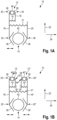
- Fig. 1A shows a first embodiment of an end effector 10 for handling objects 40, 42 in an isolator.
- the end effector 10 has a first receptacle 12 for receiving and gripping a first object 40 and a second receptacle 14 for receiving and gripping a second object 42.
- the first object 40 is smaller than the second object 42.
- the objects 40, 42 are cylindrical.
- the first object 40 has a smaller diameter than the second object 42.
- the objects 40, 42 can be, for example, vials, bottles, syringes, cylinder ampoules, filling needles, a filling needle holder, Petri dishes or agar plates.
- the first object 40 can be a vial, a bottle, a syringe, a cylinder ampoules, filling needles or a filling needle holder, in particular a tangible projection of a filling needle holder.
- the second object 42 can be a Petri dish or an agar plate.
- the first receptacle 12 and the second receptacle 14 are arranged on opposite sides of the end effector 10 in a longitudinal direction 22.
- Each receptacle 12, 14 has an opening in the longitudinal direction 22 which are oriented opposite to one another. Each opening points away from the end effector.
- Each receptacle 12, 14 has a first gripping section 26 and a second gripping section 28.
- the first gripping section 26 and the second gripping section 28 are arranged opposite one another in a transverse direction 24.
- the first object 40 can be arranged between the first gripping section 26 and the second gripping section 28 of the first receptacle 12.
- the second object 42 can be arranged between the first gripping section 26 and the second gripping section 28 of the second receptacle 14.
- the first receptacle 12 and the second receptacle 14 are of different sizes.
- the first receptacle 12 is smaller than the second receptacle 14.
- the distance between the first and second gripping sections 26, 28 of the first receptacle 12 is smaller than the distance between the first and second gripping sections 26, 28 of the second receptacle 14.
- the first receptacle 12 is thus designed for receiving and gripping the smaller first object 12, whereas the second receptacle is suitable for receiving and gripping the larger, second object 42.
- the end effector 10 further comprises a displacement element 16.
- the displacement element 16 comprises the first gripping section 26 of the first receptacle 12 at a first end 30. In particular, the displacement element 16 can form the first gripping section 26 of the first receptacle 12 at the first end 30.
- the displacement element 16 comprises the first gripping section 26 of the second receptacle 14 at a second, opposite end 32. In particular, the displacement element 16 can form the first gripping section 26 of the second receptacle 14 at the second end 32.
- the displacement element 16 thus extends from the first receptacle 12 to the second receptacle 14.
- the end effector 10 further comprises a first bearing element 18.
- the first bearing element 18 is rigidly arranged or attached to the end effector 10.
- the first bearing element 18 extends to the first receptacle 12.
- the second gripping section 28 of the first receptacle 12 is arranged at one end 34 of the first bearing element 18.
- the end effector 10 further comprises a second bearing element 20.
- the second bearing element 20 is rigidly arranged or attached to the end effector 10.
- the second bearing element 20 extends to the second receptacle 14.
- the second gripping section 28 of the second receptacle 14 is arranged at one end 36 of the second bearing element 20.
- the displacement element 16 is arranged displaceably on the end effector.
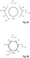
- the displacement element 16 is displaceable in particular such that the first receptacle 12 and the second receptacle 14 can each be displaced between a receiving position 44 and a gripping position 46.
- the receiving position 44 is in Fig. 5A
- the gripping position 46 is Fig. 5B shown.
- the gripping sections 26, 28 are arranged such that the corresponding object 40, 42 can be picked up or introduced between the gripping sections 26, 28.
- the distance between the gripping sections 26, 28 is so large that the corresponding object 40, 42 can be picked up or introduced between the gripping sections 26, 28.
- the distance between the gripping sections 26, 28 is larger than the diameter of the respective object 40, 42.
- the gripping sections 26, 28 are arranged such that the corresponding object 40, 42 can be gripped.
- the distance between the gripping sections 26, 28 is smaller than in the receiving position 44.
- the distance between the gripping sections 26, 28 is so small that the gripping sections 26, 28 rest on both sides of the corresponding object 40, 42 and hold or clamp it between them.
- the gripping sections 26, 28 can each be designed as a recess at the ends of the corresponding elements 16, 18, 20. Each recess has a first edge section 48 and a second, opposite edge section 50. In the gripping position 46, the corresponding object 40, 42 rests at least on the first edge section 48 and the second edge section 50.
- a depth of the gripping sections 26, 28 of the first receptacle 12 designed as a recess is smaller than half the diameter of the first object 40 in the transverse direction 24.
- a depth of the gripping sections 26, 28 of the second receptacle 14 designed as a recess is smaller than half the diameter of the second object 42 in the transverse direction 24.
- a depth of the recesses can also be deeper than half the diameter of the corresponding object if the object rests against the edge sections in such a way that it protrudes into the recess by less than half the diameter of the corresponding object.
- the displacement element 16 can be displaced translationally in the transverse direction 24.
- the end effector can, for example, have a drive device which is designed to move the displacement element 16 in the transverse direction 24.
- the bearing element 18 and the bearing element 20 are arranged on the same side of the displacement element 16 in the transverse direction 24. Accordingly, the first gripping sections 26, 28 of the first and second receptacles 12, 14 are also arranged on the same side of the displacement element 16 in the transverse direction 24. In other words, the first and second receptacles 12, 14 are arranged on the same side of the displacement element 16 in the transverse direction 24.
- each receptacle 12, 14 increases or decreases in size to the same extent.
- the receptacles 12, 14 are displaced together between the receiving position 44 and the gripping position 46.
- the displacement element 16 can be displaced in such a way that when the first receptacle 12 is arranged in the receiving position 44, the second receptacle 14 is also arranged in the receiving position 44 and when the first receptacle 12 is arranged in the gripping position 46, the second receptacle 14 is also arranged in the gripping position 46.
- the end effector 10 can further comprise a first spring element 19.
- the first spring element 19 is designed to pre-tension the first receptacle 12 in the gripping position 46.
- the first spring element 19 is arranged between the displacement element 16 and the bearing element 18.
- the end effector 10 can further comprise a second spring element 21.
- the second spring element 21 is designed to preload the second receptacle 14 in the gripping position 46.
- the second spring element 19 is arranged between the displacement element 16 and the bearing element 20 for this purpose.
- both receptacles 12, 14 can be preloaded together in the gripping position.
- Fig. 1B shows a second embodiment of an end effector 10 for handling objects 40', 40", 42 in an isolator.
- the end effector 10 of the second embodiment has a similar structure to the end effector 10 of the first embodiment. Identical elements are identified by the same reference numerals and are not explained further.
- the end effector 10 of the second embodiment differs from the end effector 10 of the first embodiment in that the end effector 10 of the second embodiment has two first receptacles 12', 12", two displacement elements 16', 16", two first bearing elements 18', 18", but no second bearing element 20.
- the first receptacles 12', 12" are each designed to receive and grip a first object 40', 40".
- the first objects 40', 40" are preferably the same.
- Each receptacle 12', 12", 14 also has a first and a second gripping section 26, 28.
- the bearing elements 18', 18" are designed to correspond to the bearing element 18.
- the displacement elements 16', 16" are designed to correspond to the displacement element 16.
- the displacement element 16' has the first gripping portion 26 of the receptacle 12' at a first end 30'.
- the displacement element 16' has the first gripping portion 26 of the receptacle 14 at a second, opposite end 32'.
- the displacement element 16" has the first gripping portion 26 of the receptacle 12" at a first end 30".
- the displacement element 16" has the second gripping portion 28 of the receptacle 14 at a second, opposite end 32".
- the bearing element 18' has the second gripping section 28 of the receptacle 12' at one end 34'.
- the bearing element 18" has the second gripping section 28 of the receptacle 12" at one end 34".
- the receptacles 12' and 12" are spaced apart from one another in the transverse direction 24.
- the receptacles 12' and 12" are arranged at substantially the same height in the longitudinal direction 22. Accordingly, the displacement elements 16', 16" are spaced apart from one another in the transverse direction 24.
- the bearing elements 18' and 18" are also spaced apart from one another in the transverse direction 24.
- the bearing elements 18' and 18" are arranged between the displacement elements 16', 16". Accordingly, the receptacles 12' and 14 are in the transverse direction 24 on the same side of the displacement element 16' and the receptacles 12" and 14 are arranged in the transverse direction 24 on the same side of the displacement element 16".
- the bearing elements 18' and 18" can basically be arranged rigidly or movably on the end effector 10. In the Fig. 1B In the embodiment shown, the bearing elements 18' and 18" are rigidly, i.e. firmly, attached to the end effector.
- the displacement elements 16', 16" can be displaced translationally in the transverse direction 24.
- the end effector can each have a drive device that is designed to displace the corresponding displacement element 16', 16" in the transverse direction 24.
- only one drive device can be provided that can displace both displacement elements 16', 16" in the transverse direction 24.
- the drive devices are preferably controlled in such a way that the displacement elements 16', 16" are displaced in opposite directions. In other words, the displacement elements 16', 16" are moved either towards or away from each other in the transverse direction 24 by means of the drive devices.
- each receptacle 12', 12", 14 is displaced into the gripping position 46. If the displacement elements 16' and 16" are displaced away from one another in the transverse direction 24, each receptacle 12', 12", 14 is displaced into the gripping position 44.
- the displacement elements 16' and 16" are displaceable in such a way that when the first receptacle 12', 12" is arranged in the gripping position 44, the second receptacle 14 is also arranged in the gripping position 44 and when the first receptacle 12', 12" is arranged in the gripping position 46, the second receptacle 14 is also arranged in the gripping position 46.
- the end effector 10 can further comprise one or two first spring elements 19', 19".
- the first spring elements 19', 19" are each designed to pre-tension one of the first receptacles 12', 12" in the gripping position 46.
- the first spring elements 19', 19" are each arranged between the corresponding displacement element 16', 16" and the corresponding first bearing element 18', 18".
- the end effector 10 can further comprise a second spring element 21.
- the second spring element 21 is designed to pre-tension the second receptacle 14 in the gripping position 46.
- the second spring element 19 is arranged between the first displacement element 16' and the second displacement element 16".
- all receptacles 12', 12", 14 can be preloaded together in the gripping position 46.
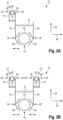
- Fig. 2A shows a third embodiment of an end effector 10 for handling objects 40, 42 in an isolator.
- the end effector 10 of the third embodiment essentially corresponds to the end effector 10 of the first embodiment. Identical elements are identified by the same reference numerals and are not explained further.
- the end effector 10 of the third embodiment differs from the end effector 10 of the first embodiment in that the first bearing element 18 and the bearing element 20 are arranged on opposite sides of the displacement element 16 in the transverse direction 24. Accordingly, the first gripping sections 26, 28 of the first and second receptacles 12, 14 are also arranged on opposite sides of the displacement element 16 in the transverse direction 24. In other words, the first and second receptacles 12, 14 are arranged on opposite sides of the displacement element 16 in the transverse direction 24.
- the displacement element 16 of the end effector 10 of the third embodiment can also be displaced translationally in the transverse direction 22. If the displacement element 16 is displaced in the transverse direction 24, each receptacle 12, 14 is alternately enlarged or reduced in size. As a result, the receptacles 12, 14 are alternately displaced between the receiving position 44 and the gripping position 46. In other words, the displacement element 16 can be displaced such that when the first receptacle 12 is arranged in the receiving position 44, the second receptacle 14 is arranged in the gripping position 46 and when the first receptacle 12 is arranged in the gripping position 46, the second receptacle 14 is also arranged in the receiving position 44.
- the end effector 10 of the third embodiment has either the first spring element 19 for preloading the first receptacle 12 into the gripping position 46 or the second spring element 21 for preloading the second receptacle 14 into the gripping position 46.
- Fig. 2B shows a fourth embodiment of an end effector 10 for handling objects 40', 40", 42 in an isolator.
- the end effector 10 of the fourth embodiment corresponds essentially to the end effector 10 of the second embodiment.
- the same elements are identified by the same reference numerals and are not explained in more detail.
- the end effector 10 of the fourth embodiment differs from the end effector 10 of the second embodiment in that the second receptacle 14 is arranged between the displacement elements 16', 16", while each first receptacle 12', 12" is arranged on the side of the corresponding displacement element 16', 16" facing away from the second receptacle 14.
- the receptacles 12', 12" are displaced into the receiving position 44, while the receptacle 14 is displaced into the gripping position 46. If the displacement elements 16' and 16" are displaced away from one another in the transverse direction 24, the receptacles 12', 12" are displaced into the gripping position 46, while the second receptacle 14 is displaced into the receiving position 44.
- the displacement elements 16' and 16" are displaceable such that when the first receptacles 12', 12" are arranged in the receiving position 44, the second receptacle 14 is arranged in the gripping position and when the first receptacles 12', 12" are arranged in the gripping position 46, the second receptacle 14 is arranged in the receiving position 44.
- the end effector 10 of the fourth embodiment has either the first spring elements 19', 19" for pre-tensioning the first receptacles 12', 12" into the gripping position 46 or the second spring element 21 for pre-tensioning the second receptacle 14 into the gripping position 46.
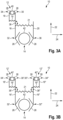
- Fig. 3A shows a fifth embodiment of an end effector 10 for handling objects 40, 42 in an isolator.
- the end effector 10 of the fifth embodiment corresponds essentially to the end effector 10 of the third embodiment. Identical elements are identified by the same reference numerals and are not explained further.
- the end effector 10 of the fifth embodiment differs from the end effector of the third embodiment in that the displacement element 16 of the end effector 10 of the fifth embodiment is rotatably displaceable about an axis of rotation 38.
- the axis of rotation 38 is arranged perpendicular to the longitudinal direction 22 and perpendicular to the transverse direction 24.
- the axis of rotation 38 is arranged between the first end 30 and the second end 32 of the displacement element 16.
- each receptacle 12, 14 increases or decreases simultaneously.
- the receptacles 12, 14 are displaced together between the receiving position 44 and the gripping position 46.
- the displacement element 16 can be displaced in such a way that when the first receptacle 12 is arranged in the receiving position 44, the second receptacle 14 is also arranged in the receiving position 44 and when the first receptacle 12 is arranged in the gripping position 46, the second receptacle 14 is also arranged in the gripping position 46.
- the end effector of the fifth embodiment can have the first spring element 19 and/or the second spring element 21.
- first and/or the second spring element 19, 21 both receptacles 12, 14 can be preloaded together in the gripping position.
- Fig. 3B shows a sixth embodiment of an end effector 10 for handling objects 40', 40", 42 in an isolator.
- the end effector 10 of the sixth embodiment corresponds essentially to the end effector 10 of the fourth embodiment. Identical elements are identified by the same reference numerals and are not explained in more detail.
- the end effector 10 of the sixth embodiment differs from the end effector 10 of the fourth embodiment in that the displacement elements 16', 16" of the end effector 10 of the sixth embodiment can be displaced in a rotational manner about a first axis of rotation 38', 38".
- the first axes of rotation 38', 38" are arranged parallel to one another and are each arranged perpendicular to the longitudinal direction 22 and perpendicular to the transverse direction 24.
- Each axis of rotation 38', 38" is between the first End 30', 30" and the second end 32', 32" of the corresponding displacement element 16', 16".
- the respective drive devices are designed to rotate the corresponding displacement element 16', 16" in opposite directions about the rotation axes 38', 38".
- the first ends 30', 30" and the second ends 32', 32" are either pivoted towards or away from each other.
- the displacement elements 16' and 16" are rotated about rotation axes 38', 38" such that the second ends 32', 32" are pivoted towards one another, the receptacles 12', 12" are displaced into the gripping position 46, while the receptacle 14 is also displaced into the gripping position 46. If the displacement elements 16' and 16" are rotated about rotation axes 38', 38" such that the second ends 32', 32" are pivoted away from one another, the receptacles 12', 12" are displaced into the receptacle position 44, while the second receptacle 14 is also displaced into the receptacle position 44.
- the displacement elements 16' and 16" are displaceable such that when the first receptacles 12', 12" are arranged in the receiving position 44, the second receptacle 14 is arranged in the receiving position 44 and when the first receptacles 12', 12" are arranged in the gripping position 46, the second receptacle 14 is also arranged in the gripping position 46.
- the end effector of the sixth embodiment can have the first spring elements 19', 19" and/or the second spring element 21.
- first spring elements 19', 19" and/or the second spring element 21 By means of the first spring elements 19', 19" and/or the second spring element 21, all receptacles 12', 12", 14 can be preloaded together in the gripping position 46.
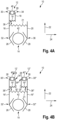
- Fig. 4A shows a seventh embodiment of an end effector 10 for handling objects 40, 42 in an isolator.
- the end effector 10 of the seventh embodiment corresponds essentially to the end effector 10 of the first embodiment.
- the same elements are identified by the same reference numerals and are not explained further.
- the end effector 10 of the seventh embodiment differs from the end effector of the first embodiment in that the displacement element 16 is rotatably displaceable about the axis of rotation 38.
- the axis of rotation 38 is arranged perpendicular to the longitudinal direction 22 and perpendicular to the transverse direction 24.
- the axis of rotation 38 is between the first end 30 and the second end 32 of the displacement element 16.
- each receptacle 12, 14 is alternately enlarged or reduced in size.
- the receptacles 12, 14 are alternately displaced between the receiving position 44 and the gripping position 46.
- the displacement element 16 can be displaced in such a way that when the first receptacle 12 is arranged in the receiving position 44, the second receptacle 14 is arranged in the gripping position 46 and when the first receptacle 12 is arranged in the gripping position 46, the second receptacle 14 is also arranged in the receiving position 44.
- the end effector 10 of the third embodiment has either the first spring element 19 for preloading the first receptacle 12 into the gripping position 46 or the second spring element 21 for preloading the second receptacle 14 into the gripping position 46.
- Fig. 4B shows an eighth embodiment of an end effector 10 for handling objects 40', 40", 42 in an isolator.
- the end effector 10 of the eighth embodiment essentially corresponds to the end effector 10 of the second embodiment.
- the same elements are identified by the same reference numerals and are not explained in more detail.
- the end effector 10 of the eighth embodiment differs from the end effector 10 of the second embodiment in that the displacement elements 16', 16" of the end effector 10 of the eighth embodiment can be displaced in a rotational manner about a rotation axis 38', 38".
- the rotation axes 38', 38" are arranged parallel to one another and are each arranged perpendicular to the longitudinal direction 22 and perpendicular to the transverse direction 24.
- Each rotation axis 38', 38" is arranged between the first end 30', 30" and the second end 32', 32" of the corresponding displacement element 16', 16".
- the respective drive devices are designed to rotate the corresponding displacement element 16', 16" in opposite directions of rotation about the rotation axes 38', 38".
- the first ends 30', 30" and the second ends 32', 32" are either pivoted towards or away from each other.
- the displacement elements 16' and 16" are rotated about rotation axes 38', 38" such that the second ends 32', 32" are pivoted towards one another, the receptacles 12', 12" are displaced into the receiving position 44, while the receptacle 14 is displaced into the gripping position 46. If the displacement elements 16' and 16" are rotated about rotation axes 38', 38" such that the second ends 32', 32" are pivoted away from one another, the receptacles 12', 12" are displaced into the gripping position 46, while the second receptacle 14 is displaced into the receiving position 44.
- the displacement elements 16' and 16" are displaceable such that when the first receptacles 12', 12" are arranged in the receiving position 44, the second receptacle 14 is arranged in the gripping position and when the first receptacles 12', 12" are arranged in the gripping position 46, the second receptacle 14 is also arranged in the receiving position 44.
- the end effector 10 of the fourth embodiment has either the first spring elements 19', 19" for pre-tensioning the first receptacles 12', 12" into the gripping position 46 or the second spring element 21 for pre-tensioning the second receptacle 14 into the gripping position 46.
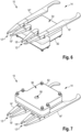
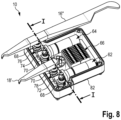
- the Figures 6 to 10 show a ninth embodiment of an end effector 10 for handling objects 40', 40", 42 in an isolator.
- the end effector 10 of the ninth embodiment corresponds essentially to the end effector 10 of the eighth embodiment.
- the same elements are identified by the same reference numerals and are not explained in more detail.
- the end effector 10 of the ninth embodiment differs from the end effector 10 of the eighth embodiment in that the bearing elements 18' and 18" are each mounted on the end effector 10 so as to be rotatable about a second axis of rotation 80', 80", wherein the second axes of rotation 80', 80" are arranged parallel to the first axes of rotation 38', 38".
- the ninth embodiment shows in detail how the displacement elements 16', 16" and the bearing elements 18', 18" can be moved in a coupled manner.
- the end effector 10 of the ninth embodiment further comprises a first drive device 62 which is designed to move the displacement element 16' and the bearing element 18'.
- the end effector 10 further comprises a second Drive device 64 which is designed to move the displacement element 16" and the bearing element 18".
- the end effector 10 has a drive device 62, 64 for displacing one of the displacement elements 16', 16" and one of the bearing elements 18', 18".
- Each drive device 62, 64 is designed to rotate the corresponding displacement element 16', 16" about the respective first axis of rotation 38', 38" and to rotate the corresponding bearing element 18', 18" about the respective second axis of rotation 80', 80".
- the first drive device 62 has a first drive shaft 72, by means of which the displacement element 16' and the bearing element 18' are driven.
- the second drive device 64 has a second drive shaft 74, by means of which the displacement element 16" and the bearing element 18" are driven.
- the longitudinal axes of the drive shafts 72, 74 are arranged parallel to one another and perpendicular to the first and second axes of rotation 38', 38", 80', 80".
- the longitudinal axes of the drive shafts 72, 74 can be arranged parallel to the longitudinal direction 22.
- the end effector 10 can further comprise a distribution device 66.
- the distribution device 66 can be designed to supply the electronic components of the end effector 10 with electrical energy (operating voltage) and/or to provide the electronic components of the end effector 10 with control signals from a control device.
- the distribution device 66 can comprise a plurality of terminals for signal lines and/or power lines.
- the end effector 10 can further comprise a storage device for storing electrical energy.
- the storage device can be a battery or an accumulator, for example.
- the drive devices 62, 64 can be electrically coupled to the storage device.
- the drive devices 62, 64 can be electrically connected to the storage device, for example, via the distribution device 66.
- the distribution device 66 can also comprise the storage device.
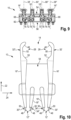
- the end effector 10 has a corresponding first coupling element 68 for each displacement element 16', 16".
- Each first coupling element 68 is rotationally fixed to the corresponding displacement element 16', 16".
- Each first coupling element 68 is rotatably mounted about the corresponding first axis of rotation 38', 38".
- each displacement element 16', 16" is rotatably mounted on the end effector 10 about the respective first axis of rotation 38', 38" by means of the corresponding first coupling element 68.
- Each first coupling element 68 is coupled to the corresponding drive shaft 72, 74.
- each first coupling element 68 has a first toothed section 76 which is in engagement with the corresponding drive shaft 72, 74.
- each drive shaft 72, 74 may have a thread and each first toothing section 76 may have teeth distributed in a circumferential direction about the respective first axis of rotation 38', 38", wherein the thread of each drive shaft 72, 74 engages with the teeth of the corresponding first toothing section 76. If the drive shafts 72, 74 are rotated about the respective longitudinal axes, the corresponding coupling elements 68 and thereby also the corresponding displacement elements 16', 16" are rotated about the respective first axis of rotation 38', 38".
- the end effector 10 has a corresponding second coupling element 70 for each bearing element 18', 18".
- Each second coupling element 70 is connected in a rotationally fixed manner to the corresponding bearing element 18', 18".
- Each second coupling element 70 is rotatably mounted about the corresponding second axis of rotation 80', 80".
- each bearing element 18', 18" is rotatably mounted on the end effector 10 about the respective second axis of rotation 80', 80" by means of the corresponding second coupling element 70.
- Each second coupling element 70 is coupled to the corresponding drive shaft 72, 74.
- each second coupling element 70 has a second toothed section 78 which engages with the corresponding drive shaft 72, 74.
- each second toothed section 78 can have teeth which are distributed in a circumferential direction about the respective second axis of rotation 80', 80", wherein the thread of each drive shaft 72, 74 engages with the teeth of the corresponding second toothed section 78. If the drive shafts 72, 74 are rotated about the respective longitudinal axes, the corresponding second coupling elements 70 and thereby also the corresponding bearing elements 18', 18" are rotated about the respective second axis of rotation 80', 80".
- first coupling element 68 and a second coupling element 70 are each engaged with a drive shaft 72, 74, when one of the drive shafts 72, 74 rotates, both the first coupling element 68 and the second coupling element 70 are rotated about the corresponding first axis of rotation or second axis of rotation 38', 38", 80', 80".
- the rotational movements of each displacement element 16', 16" and the corresponding bearing element 18', 18" are coupled to one another.
- the respective drive shaft 72, 74 is arranged between the corresponding first and second coupling elements 68, 70.
- the first coupling element 68 and the second coupling element 70 are rotated in opposite directions of rotation, so that the gripping sections 26, 28 of the respective first receptacles 12', 12" are moved towards or away from each other.
- the end effector 10 has a housing 82.
- the housing 82 has a top side 54 and a bottom side 56.
- the drive devices 62, 64 and the distributor device 66 are arranged in the housing 82.
- the displacement elements 16', 16" and the bearing elements 18', 18" are arranged outside the housing 82 on the top side 54.
- the coupling elements 68, 70 extend from the corresponding displacement elements 16', 16" and bearing elements 18', 18" into the housing.
- the housing has four corresponding holes on the top side through which the coupling elements 68, 70 are introduced into the housing.
- the housing also has a bore 58 on the underside 56.
- a bearing 60 is arranged inside the housing and is aligned with the bore.
- a bearing element of a robot can be guided through the bore 58 from the outside and coupled to the bearing 60 in order to rotatably mount the end effector 10 on the robot.
- An axis of rotation of this bearing is preferably parallel to the first and second axes of rotation 38', 38", 80', 80".
- Signal lines and/or control lines can be introduced into the housing through the hole 58.
- the signal lines and/or control lines can be coupled, for example, to the distribution device 66.
- the signal lines and/or control lines can also be connected directly to the electronic components of the end effector, for example, the drive devices 62, 64, in order to control the electronic components and supply them with electrical energy.
- the gripping sections 26, 28 of the first receptacles 12', 12" are designed as V-shaped recesses and each have a first edge section 48 and a second edge section 50 which adjoin one another and are arranged at an angle to one another.
- the first and second edge sections 48, 50 adjoin one another in particular at the lowest point of the recess.
- the gripping sections 26, 28 of the second receptacle 14 are designed as a recess and each have a first edge section 48, a second edge section 50 and an intermediate section 52 which is arranged between the first and the second edge section 48, 50.
- the first and second edge sections 48, 50 are arranged at an angle to one another.
- the intermediate section 52 forms in particular the deepest section of the recess, wherein the depth of the recess remains the same along the intermediate section 52.
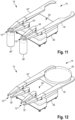
- FIG. 11 The arrangement of two first objects 40', 40" in the first receptacles 12', 12" is shown as an example.
- the first objects 40', 40" in this case are two identically designed bottles. Accordingly, vials, carpules, syringes and/or cylinder ampoules can also be arranged in the first receptacles 12', 12".
- a second object 42 in the second receptacle 14 is shown as an example.
- the second object 42 in this case is an agar plate or Petri dish.
- Fig. 13 shows an embodiment of a robot 100 for handling objects in an isolator.
- the robot has an end effector 10 and a support structure 102 for supporting the end effector 10.
- the end effector 10 can be designed according to one of the Figures 1 to 12 described embodiments.
- the robot 100 is designed to move and align the end effector 10 in the isolator.
- the support structure 102 can be designed to be articulated.
- the support structure 102 can, for example, have several arms that are coupled to one another via joints.
- the support structure 102 of the robot 100 can be designed to be movable in such a way that the end effector 10 in the isolator can be moved by means of the robot 100.
- the robot 100 can, for example, have one or more drive devices.
- the end effector can be rotatably mounted at one end of the support structure. In this way, the receptacles 12, 14 of the end effector 10 in the isolator can be aligned with respect to the objects 40, 42 to be picked up.
- the robot 100 can also have a further drive device for rotating the end effector 10.
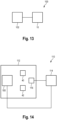
- Fig. 14 shows an embodiment of a system 110 for handling objects 40, 42 in an isolator 112.
- the system comprises the isolator 112 and a robot 100.
- the robot 100 can be operated in accordance with the Figures 13 described embodiment.
- a first object 40 and/or a second object 42 can be arranged in the insulator 112.
- the system further comprises a control device 114.
- the control device 114 is designed to control the movement of the end effector 10 and/or the robot 100.
- the control device 114 can, for example, control at least one drive device of the end effector 10 in order to move the receptacles 12, 14 between the receiving position 44 and the gripping position 46.
- the control device 114 can, for example, send control signals to the drive devices 62, 64 of the end effector.
- control device 114 can control the robot 100 to move and align the end effector 10 in the isolator 112.
- the control device 114 can, for example, send control signals to the corresponding drive devices of the robot 100.
- the system can further comprise a sensor device 116.
- the sensor device 116 is designed to detect the position and orientation of the end effector 10 and the objects 40, 42 in the isolator 112.
- the sensor device 116 sends sensor signals to the control device 114, wherein the sensor signals contain information about the detected position and orientation of the end effector 10 and the objects 40, 42 in the isolator 112.
- the control device 114 is designed to control the robot 100 and the end effector 10 based on the sensor signals.
- the control device 114 controls the end effector 10 such that the first receptacle 12 is arranged in the receiving position 44 or is moved into it.
- the control device 114 controls the robot 100 such that the end effector 10 in the isolator 112 is moved to the position of the first object 40.
- the end effector 10 will be moved such that the first object 40 can be received in the first receptacle 12.
- the end effector 10 in the isolator 112 is moved and aligned such that the first object 40 is arranged in the first receptacle 12.
- the control device 114 controls the end effector 10 such that the first receptacle 12 is displaced into the gripping position 46 in order to grip the first object 40.
- the control device 114 then controls the robot 100 such that the robot 100 further moves the end effector 10 in the isolator 112, whereby the first object 40 gripped in the first receptacle 12 can be transferred to a target position in the isolator 112.
- control device 114 controls the end effector 10 such that the first holder 12 is moved from the gripping position 46 to the receiving position 44 in order to release the first object 40 again.
- the second object 42 can also be received, gripped, transferred and released again in the second holder 14 in a corresponding manner.
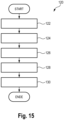
- Fig. 15 shows an embodiment of a method 120 for handling objects 40, 42 in the isolator 112.
- the method can be derived from the previously described system 110 Fig. 14 be executed.
- the first receptacle 12 or the second receptacle 14 is arranged in the receiving position 44 in which the first object 40 or second object 42 can be received in the corresponding receptacle 12, 14. If the end effector 10 has two first receptacles 12', 12", both first receptacles 12', 12" are arranged in the receiving position 44.
- the respective object 40, 42 is recorded in the corresponding recording 12, 14. If the end effector 10 has two first recordings 12', 12", a first object 40', 40" can be recorded in each first recording 12', 12".
- the respective object 40, 42 is gripped by displacing the displacement element 16 such that the corresponding receptacle 12, 14 is displaced from the receiving position 44 into the gripping position 46 in which the respective object 40, 42 can be gripped. If the end effector 10 has two first receptacles 12', 12", the two displacement elements 16', 16" are displaced such that the first receptacle 12', 12" or the second receptacle 14 is displaced from the receiving position 44 into the gripping position 46, depending on whether two first objects 40', 40" or a second object 42 are to be gripped.
- the respective object 40, 42 is handled by moving the end effector 10 by means of the robot 100 in the isolator 112 while the respective object 40, 42 is gripped.
- the end effector 10 can be moved and aligned in the isolator 112 such that the respective object 40, 42 is transferred to a target position.
- the respective object 40, 42 is released again by displacing the displacement element 16 such that the corresponding receptacle 12, 14 is displaced from the gripping position 46 to the receiving position 44. If the end effector 10 has two first receptacles 12', 12", the two displacement elements 16', 16" are displaced such that the first receptacle 12', 12" or the second receptacle 14 is displaced from the gripping position 46 to the receiving position 44, depending on whether two first objects 40', 40" or a second object 42 are to be released.
Landscapes
- Engineering & Computer Science (AREA)
- Robotics (AREA)
- Mechanical Engineering (AREA)
- Manipulator (AREA)
Claims (15)
- Effecteur terminal (10) permettant de manipuler des objets (40, 42) dans un isolateur (112),dans lequel l'effecteur terminal (10) présente un premier réceptacle (12) pour un premier objet (40), un second réceptacle (14) pour un second objet (42), et un premier élément de déplacement (16), dans lequel les réceptacles (12, 14) sont disposés dans une direction longitudinale (22) sur des côtés opposés de l'effecteur terminal (10), dans lequel chaque réceptacle (12, 14) peut être déplacé entre une position de réception (44), dans laquelle l'objet (40, 42) respectif peut être reçu dans le réceptacle (12, 14) correspondant, et une position de préhension (46), dans laquelle l'objet (40, 42) respectif peut être saisi par le réceptacle (12, 14) correspondant, dans lequel chaque réceptacle (12, 14) présente une première section de préhension (26), dans lequel la première section de préhension (26) du premier réceptacle (12) est disposée à une première extrémité (30) de l'élément de déplacement (16) et la première section de préhension (26) du second réceptacle (14) est disposée à une seconde extrémité (32) opposée de l'élément de déplacement (16), dans lequel l'élément de déplacement (16) peut être déplacé de telle sorte que le premier réceptacle (12) et le second réceptacle (14) peuvent être déplacés respectivement entre la position de réception (44) et la position de préhension (46),caractérisé en ce que l'effecteur terminal (10) présente deux premiers réceptacles (12', 12") et deux éléments de déplacement (16', 16"), dans lequel la première section de préhension (26) de respectivement l'un des premiers réceptacles (12', 12") est disposée à la première extrémité (30', 30") de chaque élément de déplacement (16', 16"), dans lequel respectivement la première section de préhension (26) et la seconde section de préhension (28) du second réceptacle (14) sont disposées aux secondes extrémités (32', 32") opposées des éléments de déplacement (16', 16").
- Effecteur terminal (10) selon la revendication 1, dans lequel l'élément de déplacement (16) peut être déplacé de telle sorte que, lorsque le premier réceptacle (12) est disposé dans la position de réception (44), le second réceptacle (14) est disposé dans la position de préhension (46) et, lorsque le second réceptacle (14) est disposé dans la position de réception (44), le premier réceptacle (12) est disposé dans la position de préhension (46).
- Effecteur terminal (10) selon la revendication 1, dans lequel l'élément de déplacement (16) peut être déplacé de telle sorte que, lorsque le premier réceptacle (12) est disposé dans la position de réception (44), le second réceptacle (14) est disposé dans la position de réception (44) et, lorsque le second réceptacle (14) est disposé dans la position de préhension (46), le premier réceptacle (12) est disposé dans la position de préhension (46).
- Effecteur terminal (10) selon l'une des revendications 1 à 3, dans lequel chaque réceptacle (12, 14) présente une seconde section de préhension (28), dans lequel la première section de préhension (26) et la seconde section de préhension (28) sont disposées en vis-à-vis dans une direction transversale (24), en particulier dans lequel la direction longitudinale (22) est disposée sensiblement perpendiculairement à la direction transversale (24).
- Effecteur terminal (10) selon l'une des revendications 1 à 4, dans lequel l'élément de déplacement (16) peut être déplacé en translation ou en rotation.
- Effecteur terminal (10) selon la revendication 5, dans lequel l'élément de déplacement (16) peut coulisser dans la direction transversale (24).
- Effecteur terminal (10) selon la revendication 5, dans lequel l'élément de déplacement (16) est monté de manière à pouvoir tourner autour d'un premier axe de rotation (38), dans lequel le premier axe de rotation (38) est disposé perpendiculairement à la direction longitudinale (22) et à la direction transversale (24), en particulier dans lequel le premier axe de rotation (38) est disposé entre la première extrémité (30) et la seconde extrémité (32).
- Effecteur terminal (10) selon l'une des revendications 4 à 7, dans lequel l'effecteur terminal (10) présente en outre, pour au moins l'un des réceptacles (12, 14), un élément de support (18, 20), dans lequel la seconde section de préhension (28) du réceptacle respectif est disposée à une extrémité (34, 36) de l'élément de support (18, 20) correspondant.
- Effecteur terminal (10) selon la revendication 8, dans lequel l'élément de déplacement (16) et l'élément de support (18, 20) présentent respectivement un évidement aux extrémités (30, 32, 34, 36) correspondantes, dans lequel les évidements forment les sections de préhension (26, 28) correspondantes.
- Effecteur terminal (10) selon la revendication 8 ou 9, dans lequel l'élément de support (18, 20) est disposé de manière fixe ou mobile sur l'effecteur terminal (10).
- Effecteur terminal (10) selon la revendication 10, dans lequel l'élément de support (18, 20) peut être déplacé, en particulier en translation ou en rotation, dans lequel un mouvement de l'élément de support (18, 20) est accouplé au mouvement de l'élément de déplacement (16), de sorte que, lors du déplacement de la position de réception (44) vers la position de préhension (46), les sections de préhension (26, 28) sont mues l'une vers l'autre et, lors du déplacement de la position de préhension (46) vers la position de réception (44), les sections de préhension (26, 28) sont éloignées l'une de l'autre.
- Effecteur terminal (10) selon l'une des revendications 1 à 11, dans lequel l'effecteur terminal (10) présente en outre un dispositif d'entraînement (62, 64) permettant de déplacer l'élément de déplacement (16).
- Robot (100) permettant de manipuler des objets (40, 42) dans un isolateur (112), dans lequel le robot (100) présente un effecteur terminal (10) selon l'une des revendications 1 à 12.
- Système (110) comportant un isolateur (112) et un robot (100) selon la revendication 13 disposé dans l'isolateur (112).
- Procédé (120) permettant de manipuler des objets (40, 42) dans un isolateur (112), dans lequel un robot (110) comportant un effecteur terminal (10) est disposé dans l'isolateur (112), dans lequel l'effecteur terminal (10) présente un premier réceptacle (12) pour un premier objet (40), un second réceptacle (14) pour un second objet (42), et un premier élément de déplacement (16), dans lequel les réceptacles (12, 14) sont disposés dans une direction longitudinale (22) sur des côtés opposés de l'effecteur terminal (10), dans lequel chaque réceptacle (12, 14) présente une première section de préhension (26), dans lequel la première section de préhension (26) du premier réceptacle (12) est disposée à une première extrémité (30) de l'élément de déplacement (16) et la première section de préhension (26) du second réceptacle (14) est disposée à une seconde extrémité (32) opposée de l'élément de déplacement (16), dans lequel l'élément de déplacement (16) peut être déplacé, dans lequel l'effecteur terminal (10) présente deux premiers réceptacles (12', 12") et deux éléments de déplacement (16', 16"), dans lequel la première section de préhension (26) de respectivement l'un des premiers réceptacles (12', 12") est disposée à la première extrémité (30', 30") de chaque élément de déplacement (16', 16"), dans lequel respectivement la première section de préhension (26) et la seconde section de préhension (28) du second réceptacle (14) sont disposées aux secondes extrémités (32', 32") opposées des éléments de déplacement (16', 16"), dans lequel le procédé (120) présente les étapes suivantes :- disposition (122) des premiers réceptacles (12', 12") ou du second réceptacle (14) dans une position de réception (44), dans laquelle le premier objet (40) ou le second objet (42) respectif peut être reçu dans le réceptacle (12', 12", 14) correspondant ;- réception (124) de l'objet (40, 42) respectif dans le réceptacle (12', 12", 14) correspondant ; et- saisie (126) de l'objet (40, 42) respectif en déplaçant les éléments de déplacement (16', 16") de telle sorte que le réceptacle (12', 12", 14) correspondant est déplacé de la position de réception (44) vers une position de préhension (46), dans laquelle l'objet (40, 42) respectif peut être saisi.
Applications Claiming Priority (2)
| Application Number | Priority Date | Filing Date | Title |
|---|---|---|---|
| DE102020102761.3A DE102020102761B4 (de) | 2020-02-04 | 2020-02-04 | Endeffektor, Roboter, System und Verfahren zum Handhaben von Objekten in einem Isolator |
| PCT/EP2021/052444 WO2021156262A2 (fr) | 2020-02-04 | 2021-02-02 | Effecteur terminal, robot, système et procédé pour manipuler des objets dans un isolateur |
Publications (3)
| Publication Number | Publication Date |
|---|---|
| EP4100218A2 EP4100218A2 (fr) | 2022-12-14 |
| EP4100218B1 true EP4100218B1 (fr) | 2024-11-06 |
| EP4100218C0 EP4100218C0 (fr) | 2024-11-06 |
Family
ID=74550665
Family Applications (1)
| Application Number | Title | Priority Date | Filing Date |
|---|---|---|---|
| EP21703244.0A Active EP4100218B1 (fr) | 2020-02-04 | 2021-02-02 | Effecteur terminal, robot, système et procédé pour manipuler des objets dans un isolateur |
Country Status (5)
| Country | Link |
|---|---|
| US (1) | US20220371205A1 (fr) |
| EP (1) | EP4100218B1 (fr) |
| DE (1) | DE102020102761B4 (fr) |
| ES (1) | ES3004940T3 (fr) |
| WO (1) | WO2021156262A2 (fr) |
Families Citing this family (3)
| Publication number | Priority date | Publication date | Assignee | Title |
|---|---|---|---|---|
| DE102020102765A1 (de) * | 2020-02-04 | 2021-08-05 | Groninger & Co. Gmbh | Verfahren zum Transferieren zumindest einer Füllnadel einer Anzahl von Füllnadeln in einen aseptischen Isolator |
| US20240293943A1 (en) * | 2020-12-07 | 2024-09-05 | bAhead GmbH | Tool attachment for a collaborating robot for laboratory operation |
| DE102023107664A1 (de) | 2023-03-27 | 2024-10-02 | Groninger GmbH & Co.KG | Greifvorrichtung, Greifsystem, Handhabungseinrichtung und Verfahren |
Family Cites Families (15)
| Publication number | Priority date | Publication date | Assignee | Title |
|---|---|---|---|---|
| US3968885A (en) * | 1973-06-29 | 1976-07-13 | International Business Machines Corporation | Method and apparatus for handling workpieces |
| JPS5234073B2 (fr) * | 1973-10-25 | 1977-09-01 | ||
| IT1186909B (it) * | 1985-07-17 | 1987-12-16 | M P Spa Sa | Robot programmabile per l alimentazione e lo scarico rispettivamente delle bobine vuote e delle bobine piene in e da macchine bobinatrici |
| US4845834A (en) * | 1988-02-22 | 1989-07-11 | Kearney & Trecker Corporation | Tool clamping mechanism |
| JPH06297370A (ja) * | 1993-04-15 | 1994-10-25 | Rohm Co Ltd | 電子部品製造用のマテハン装置 |
| US6393694B2 (en) * | 1999-04-23 | 2002-05-28 | Koninklijke Philips Electronics N.V. | Gripping device |
| DE202005002924U1 (de) * | 2005-02-23 | 2006-03-30 | Krones Ag | Klammergreifer für ein Gefäßtransportsystem |
| US7789443B2 (en) * | 2007-03-16 | 2010-09-07 | Axcelis Technologies, Inc. | Workpiece gripping device |
| US20090223592A1 (en) | 2008-03-04 | 2009-09-10 | Vanrx Pharmaceuticals, Inc. | Robotic filling systems and methods |
| US7604584B1 (en) | 2008-06-18 | 2009-10-20 | Campro Precision Machinery Co., Ltd. | Automatic tool-changing arm of automatic tool changer |
| JP5890623B2 (ja) | 2011-06-28 | 2016-03-22 | 株式会社安川電機 | 液体処理システム及び液体処理方法 |
| JP5582313B2 (ja) | 2011-06-28 | 2014-09-03 | 株式会社安川電機 | ロボットシステム |
| DE102016111125A1 (de) | 2016-06-17 | 2017-12-21 | Schunk Gmbh & Co. Kg Spann- Und Greiftechnik | Greifvorrichtung |
| DE102018203626B3 (de) | 2018-03-09 | 2019-08-14 | Kuka Systems Gmbh | Mehrfachgreifervorrichtung für einen Roboter |
| CN108214539A (zh) * | 2018-03-26 | 2018-06-29 | 吴爱兵 | 一种自动夹紧的弹簧式机械爪 |
-
2020
- 2020-02-04 DE DE102020102761.3A patent/DE102020102761B4/de active Active
-
2021
- 2021-02-02 ES ES21703244T patent/ES3004940T3/es active Active
- 2021-02-02 WO PCT/EP2021/052444 patent/WO2021156262A2/fr not_active Ceased
- 2021-02-02 EP EP21703244.0A patent/EP4100218B1/fr active Active
-
2022
- 2022-08-02 US US17/879,738 patent/US20220371205A1/en active Pending
Also Published As
| Publication number | Publication date |
|---|---|
| WO2021156262A3 (fr) | 2021-10-14 |
| DE102020102761A1 (de) | 2021-08-05 |
| ES3004940T3 (en) | 2025-03-13 |
| EP4100218C0 (fr) | 2024-11-06 |
| EP4100218A2 (fr) | 2022-12-14 |
| CA3166107A1 (fr) | 2021-08-12 |
| DE102020102761B4 (de) | 2022-05-25 |
| US20220371205A1 (en) | 2022-11-24 |
| WO2021156262A2 (fr) | 2021-08-12 |
Similar Documents
| Publication | Publication Date | Title |
|---|---|---|
| EP4100218B1 (fr) | Effecteur terminal, robot, système et procédé pour manipuler des objets dans un isolateur | |
| EP3416787B1 (fr) | Dispositif effecteur pour un robot, dispositif de travail pourvu d'un robot et procédé de changement d'effecteur dans des robots | |
| EP3481605B1 (fr) | Procédé et système de changement automatique d'arbres | |
| EP2144067A1 (fr) | Agencement de robot de laboratoire | |
| EP3197647B1 (fr) | Système de préhension destiné à un dispositif de manipulation, dispositif de manipulation muni d'un système de préhension, et procédé permettant de saisir une pièce au moyen du système de préhension | |
| EP4267499A2 (fr) | Dispositif de manipulation pour contenants pharmaceutiques, et système de traitement pour contenants pharmaceutiques équipé d'un dispositif de manipulation | |
| DE102009039104A1 (de) | Greifer, Verfahren zum Wechseln wenigstens eines Aufsatzbackens eines Greifers, sowie frei programmierbarer Manipulator mit einem solchen Greifer | |
| DE102016004788A1 (de) | Verfahren zur Herstellung eines Roboters und Vorrichtung zur Durchführung dieses Verfahrens | |
| DE102016111042A1 (de) | Greifvorrichtung | |
| DE3705884C2 (fr) | ||
| DE202015102825U1 (de) | Stopfenfügewerkzeug | |
| EP3664959B1 (fr) | Procédé et dispositif de fourniture de vis | |
| DE3100401A1 (de) | "greifvorrichtung" | |
| DE112019004638T5 (de) | Elektrischer Werkzeugwechsler | |
| DE102013225116A1 (de) | Handhabungseinheit | |
| DE102016225203A1 (de) | Roboterklemmgreifer mit einer arretierbaren Verstellvorrichtung und zugehöriges Verfahren | |
| DE102019108737B3 (de) | Anordnung, aufweisend eine Spannvorrichtung und Verfahren zum Einspannen eines Werkstücks | |
| DE102019201169A1 (de) | Robotergreifer mit einem Kraftsensor | |
| EP4277769B1 (fr) | Dispositif de préhension et système comprenant un dispositif de préhension | |
| DE102016210796B4 (de) | Greifsystem für eine kameraunterstützte Entnahme eines Bauteils aus einem Behälter | |
| DE10244964B4 (de) | Vorrichtung und Verfahren zur automatischen Bestückung von Klemm-Magazinen mit Werkstücken | |
| EP3878592B1 (fr) | Magasin de capsules et unité de magasin de capsules | |
| DE102019100633B3 (de) | Greifwerkzeug und Verfahren | |
| DE102009030755B4 (de) | Handhabungsvorrichtung mit Scherenarm | |
| DE102023116737A1 (de) | Haltevorrichtung, Werkzeugmaschine und Bearbeitungssystem |
Legal Events
| Date | Code | Title | Description |
|---|---|---|---|
| STAA | Information on the status of an ep patent application or granted ep patent |
Free format text: STATUS: UNKNOWN |
|
| STAA | Information on the status of an ep patent application or granted ep patent |
Free format text: STATUS: THE INTERNATIONAL PUBLICATION HAS BEEN MADE |
|
| PUAI | Public reference made under article 153(3) epc to a published international application that has entered the european phase |
Free format text: ORIGINAL CODE: 0009012 |
|
| STAA | Information on the status of an ep patent application or granted ep patent |
Free format text: STATUS: REQUEST FOR EXAMINATION WAS MADE |
|
| 17P | Request for examination filed |
Effective date: 20220831 |
|
| AK | Designated contracting states |
Kind code of ref document: A2 Designated state(s): AL AT BE BG CH CY CZ DE DK EE ES FI FR GB GR HR HU IE IS IT LI LT LU LV MC MK MT NL NO PL PT RO RS SE SI SK SM TR |
|
| DAV | Request for validation of the european patent (deleted) | ||
| DAX | Request for extension of the european patent (deleted) | ||
| GRAP | Despatch of communication of intention to grant a patent |
Free format text: ORIGINAL CODE: EPIDOSNIGR1 |
|
| STAA | Information on the status of an ep patent application or granted ep patent |
Free format text: STATUS: GRANT OF PATENT IS INTENDED |
|
| INTG | Intention to grant announced |
Effective date: 20240605 |
|
| GRAS | Grant fee paid |
Free format text: ORIGINAL CODE: EPIDOSNIGR3 |
|
| GRAA | (expected) grant |
Free format text: ORIGINAL CODE: 0009210 |
|
| STAA | Information on the status of an ep patent application or granted ep patent |
Free format text: STATUS: THE PATENT HAS BEEN GRANTED |
|
| AK | Designated contracting states |
Kind code of ref document: B1 Designated state(s): AL AT BE BG CH CY CZ DE DK EE ES FI FR GB GR HR HU IE IS IT LI LT LU LV MC MK MT NL NO PL PT RO RS SE SI SK SM TR |
|
| REG | Reference to a national code |
Ref country code: GB Ref legal event code: FG4D Free format text: NOT ENGLISH |
|
| REG | Reference to a national code |
Ref country code: CH Ref legal event code: EP |
|
| REG | Reference to a national code |
Ref country code: DE Ref legal event code: R096 Ref document number: 502021005725 Country of ref document: DE |
|
| REG | Reference to a national code |
Ref country code: IE Ref legal event code: FG4D Free format text: LANGUAGE OF EP DOCUMENT: GERMAN |
|
| U01 | Request for unitary effect filed |
Effective date: 20241204 |
|
| U07 | Unitary effect registered |
Designated state(s): AT BE BG DE DK EE FI FR IT LT LU LV MT NL PT RO SE SI Effective date: 20241212 |
|
| REG | Reference to a national code |
Ref country code: ES Ref legal event code: FG2A Ref document number: 3004940 Country of ref document: ES Kind code of ref document: T3 Effective date: 20250313 |
|
| U20 | Renewal fee for the european patent with unitary effect paid |
Year of fee payment: 5 Effective date: 20250226 |
|
| PG25 | Lapsed in a contracting state [announced via postgrant information from national office to epo] |
Ref country code: HR Free format text: LAPSE BECAUSE OF FAILURE TO SUBMIT A TRANSLATION OF THE DESCRIPTION OR TO PAY THE FEE WITHIN THE PRESCRIBED TIME-LIMIT Effective date: 20241106 Ref country code: IS Free format text: LAPSE BECAUSE OF FAILURE TO SUBMIT A TRANSLATION OF THE DESCRIPTION OR TO PAY THE FEE WITHIN THE PRESCRIBED TIME-LIMIT Effective date: 20250306 |
|
| PG25 | Lapsed in a contracting state [announced via postgrant information from national office to epo] |
Ref country code: NO Free format text: LAPSE BECAUSE OF FAILURE TO SUBMIT A TRANSLATION OF THE DESCRIPTION OR TO PAY THE FEE WITHIN THE PRESCRIBED TIME-LIMIT Effective date: 20250206 |
|
| PG25 | Lapsed in a contracting state [announced via postgrant information from national office to epo] |
Ref country code: GR Free format text: LAPSE BECAUSE OF FAILURE TO SUBMIT A TRANSLATION OF THE DESCRIPTION OR TO PAY THE FEE WITHIN THE PRESCRIBED TIME-LIMIT Effective date: 20250207 |
|
| PG25 | Lapsed in a contracting state [announced via postgrant information from national office to epo] |
Ref country code: PL Free format text: LAPSE BECAUSE OF FAILURE TO SUBMIT A TRANSLATION OF THE DESCRIPTION OR TO PAY THE FEE WITHIN THE PRESCRIBED TIME-LIMIT Effective date: 20241106 |
|
| PG25 | Lapsed in a contracting state [announced via postgrant information from national office to epo] |
Ref country code: RS Free format text: LAPSE BECAUSE OF FAILURE TO SUBMIT A TRANSLATION OF THE DESCRIPTION OR TO PAY THE FEE WITHIN THE PRESCRIBED TIME-LIMIT Effective date: 20250206 |
|
| PG25 | Lapsed in a contracting state [announced via postgrant information from national office to epo] |
Ref country code: SM Free format text: LAPSE BECAUSE OF FAILURE TO SUBMIT A TRANSLATION OF THE DESCRIPTION OR TO PAY THE FEE WITHIN THE PRESCRIBED TIME-LIMIT Effective date: 20241106 |
|
| PGFP | Annual fee paid to national office [announced via postgrant information from national office to epo] |
Ref country code: ES Payment date: 20250331 Year of fee payment: 5 |
|
| PG25 | Lapsed in a contracting state [announced via postgrant information from national office to epo] |
Ref country code: SK Free format text: LAPSE BECAUSE OF FAILURE TO SUBMIT A TRANSLATION OF THE DESCRIPTION OR TO PAY THE FEE WITHIN THE PRESCRIBED TIME-LIMIT Effective date: 20241106 |
|
| PG25 | Lapsed in a contracting state [announced via postgrant information from national office to epo] |
Ref country code: CZ Free format text: LAPSE BECAUSE OF FAILURE TO SUBMIT A TRANSLATION OF THE DESCRIPTION OR TO PAY THE FEE WITHIN THE PRESCRIBED TIME-LIMIT Effective date: 20241106 |
|
| PLBE | No opposition filed within time limit |
Free format text: ORIGINAL CODE: 0009261 |
|
| STAA | Information on the status of an ep patent application or granted ep patent |
Free format text: STATUS: NO OPPOSITION FILED WITHIN TIME LIMIT |
|
| PG25 | Lapsed in a contracting state [announced via postgrant information from national office to epo] |
Ref country code: MC Free format text: LAPSE BECAUSE OF FAILURE TO SUBMIT A TRANSLATION OF THE DESCRIPTION OR TO PAY THE FEE WITHIN THE PRESCRIBED TIME-LIMIT Effective date: 20241106 |
|
| REG | Reference to a national code |
Ref country code: CH Ref legal event code: PL |
|
| 26N | No opposition filed |
Effective date: 20250807 |
|
| PG25 | Lapsed in a contracting state [announced via postgrant information from national office to epo] |
Ref country code: CH Free format text: LAPSE BECAUSE OF NON-PAYMENT OF DUE FEES Effective date: 20250228 |
|
| GBPC | Gb: european patent ceased through non-payment of renewal fee |
Effective date: 20250206 |
|
| PG25 | Lapsed in a contracting state [announced via postgrant information from national office to epo] |
Ref country code: GB Free format text: LAPSE BECAUSE OF NON-PAYMENT OF DUE FEES Effective date: 20250206 |
|
| PG25 | Lapsed in a contracting state [announced via postgrant information from national office to epo] |
Ref country code: IE Free format text: LAPSE BECAUSE OF NON-PAYMENT OF DUE FEES Effective date: 20250202 |
|
| U20 | Renewal fee for the european patent with unitary effect paid |
Year of fee payment: 6 Effective date: 20260224 |