EP4100218B1 - End effector, robot, system and method for the handling of objects in an isolator - Google Patents
End effector, robot, system and method for the handling of objects in an isolator Download PDFInfo
- Publication number
- EP4100218B1 EP4100218B1 EP21703244.0A EP21703244A EP4100218B1 EP 4100218 B1 EP4100218 B1 EP 4100218B1 EP 21703244 A EP21703244 A EP 21703244A EP 4100218 B1 EP4100218 B1 EP 4100218B1
- Authority
- EP
- European Patent Office
- Prior art keywords
- receptacle
- end effector
- gripping
- displacement
- isolator
- Prior art date
- Legal status (The legal status is an assumption and is not a legal conclusion. Google has not performed a legal analysis and makes no representation as to the accuracy of the status listed.)
- Active
Links
Images
Classifications
-
- B—PERFORMING OPERATIONS; TRANSPORTING
- B25—HAND TOOLS; PORTABLE POWER-DRIVEN TOOLS; MANIPULATORS
- B25J—MANIPULATORS; CHAMBERS PROVIDED WITH MANIPULATION DEVICES
- B25J15/00—Gripping heads and other end effectors
- B25J15/0052—Gripping heads and other end effectors multiple gripper units or multiple end effectors
Definitions
- the present invention relates to an end effector, a robot, a system and a method for handling objects in an isolator.
- end effectors can be used to handle different objects, which are suitable for handling the respective object type.
- end effectors are also known that are suitable for handling different object types. These end effectors have, for example, several tools or a multi-function tool for handling the different object types.
- a filling arm is disposed within a chamber.
- An optical sensor is configured to detect openings of the containers within the chamber. The positions of the detected openings are used to guide the filling arm to fill the containers with a product.
- the publication shows EP 2 733 196 A1 a liquid processing system for processing liquid biological material.
- the liquid processing system comprises: a body provided to rotate about an axis within a predetermined working space; a first arm provided on the body and having three degrees of freedom or higher; a second arm provided on the body and having three degrees of freedom or higher; driving means configured to drive each of the body, the first arm, and the second arm; physiochemical equipment arranged within the working space and within the movement range of at least one of the first arm and the second arm; wherein the driving means is operated by teaching based on the positions and shapes of the physiochemical equipment, and the biological material is processed using the physiochemical equipment.
- the publication shows US 7 789 443 B2 a gripper for use with a robot.
- the gripper includes a support body for releasably attaching the gripper to a movable arm and a workpiece contact body having a groove extending along at least a portion of the contact body for engaging a curved outer edge of the workpiece.
- a coupling member connects the support body to the workpiece contact member and has a flexure component that flexes to allow radial and/or tangential relative movement of the workpiece contact body with respect to the support body to reduce slippage between the workpiece and the contact body when the gripper engages the workpiece.
- the publication shows US 8 857 875 B2 a robot comprising a robot arm.
- a robot hand is arranged at a distal end of the robot arm and grasps an object.
- the robot hand includes an air chuck that includes a pair of pistons and an air cylinder.
- the air cylinder opens and closes the pistons parallel to each other.
- a pair of first gripping elements are disposed on a first side of the pistons and move close to and away from each other within a first movable range on a movable plane.
- a pair of second gripping elements are disposed on a second side of the pistons and move close to and away from each other within a second movable range that is different from the first movable range on the movable plane.
- the robot hand pivots relative to the distal end of the robot arm about a pivot axis that is approximately perpendicular to the movable plane.
- an object of the present invention to provide an end effector for handling objects in an isolator, which has the simplest possible structure and is as easy to control and manufacture as possible.
- an end effector for handling objects in an isolator comprises a first receptacle for a first object, a second receptacle for a second object, and a first displacement element, wherein the receptacles are arranged in a longitudinal direction on opposite sides of the end effector, wherein each receptacle can be moved between a receiving position in which the respective object can be received in the corresponding receptacle, and a gripping position in which the respective object can be gripped with the corresponding receptacle can be gripped, wherein each receptacle has a first gripping section, wherein the first gripping section of the first receptacle is arranged at a first end of the displacement element and the first gripping section of the second receptacle is arranged at an opposite, second end of the displacement element, wherein the displacement element is displaceable such that the first receptacle and the second receptacle can each
- the end effector has two first receptacles and two displacement elements, wherein the first gripping section of one of the first receptacles is arranged at the first end of each displacement element, wherein the first and second gripping sections of the second receptacle are arranged at the second, opposite ends of the displacement elements.
- a robot for handling objects in an isolator comprising an end effector according to the first aspect of the invention.
- a system comprising an isolator and a robot according to the second aspect of the invention arranged in the isolator.
- the objects to be handled can be, for example, vials, cartridges, bottles, syringes, cylinder ampoules, filling needles, a filling needle holder, Petri dishes, agar plates and/or the like.
- the first object is preferably a vial, a bottle, a syringe, a cylinder ampoules, filling needles or a filling needle holder, in particular a tangible projection of a filling needle holder.
- the second object is preferably a Petri dish or an agar plate.
- the term "isolator” generally refers to a container that is hermetically and gas-tightly sealed from the surrounding work area. A defined atmosphere can be created within an isolator for processing sensitive or dangerous products.
- the isolator can preferably be an aseptic isolator, which preferably has a filling area for filling objects (e.g. vials, cartridges, bottles, syringes and/or the like) with fluid using filling needles.
- Each holder has a holding position and a gripping position and can be moved between these positions.
- each holder In the holding position, each holder is opened wide enough for the holder to hold a corresponding object. In other words, the holder is opened wide enough for the corresponding object to be inserted into the holder.
- the holding position can therefore also be used as an open or open position.
- the gripping position In the gripping position, the holder is closed so far that the corresponding object is gripped by the holder. "Gripping" here means that the object is clamped or held in the holder.
- the gripping position can therefore also be referred to as the closed position.
- the first displacement element is displaceable. This means that the first displacement element is movable relative to other components of the end effector. In other words, the first displacement element is arranged displaceably on the end effector.
- the first displacement element couples the displacement of the first and second receptacles.
- the first displacement element extends from the first receptacle to the second receptacle and forms the corresponding first gripping sections of the receptacles at its ends. If the first displacement element is displaced, the gripping sections at the ends of the first displacement element are also displaced so that the receptacles are either opened further or closed further. This also displaces the receptacles between the gripping position and the receptacle position.
- the end effector is thus designed as a multifunctional tool that has two holders with which different objects can be handled. By moving the displacement element, both holders can be moved simultaneously. This means that only one drive means is required for the displacement element to move both holders.
- the end effector has two first receptacles and two displacement elements, wherein the first gripping section of one of the first receptacles is arranged at the first end of each displacement element, wherein the first and second gripping sections of the second receptacle are arranged at the second, opposite ends of the displacement elements.
- two first objects can be gripped simultaneously with the first receptacles.
- the second holder is preferably designed for handling larger objects, such as Petri dishes or agar plates, which are usually handled individually.
- the robot is designed to move and align the end effector in the isolator.
- a first object to be handled can be arranged in the isolator.
- the first receptacle can be moved or arranged in the receiving position.
- the robot can then move the end effector in the isolator to the position of the object.
- the end effector can be moved so that the first object is received in the first receptacle.
- the first receptacle can be moved to the gripping position in order to grip the object.
- the robot can then move the end effector further in the isolator, whereby the first object gripped in the first receptacle can be transferred in space.
- the first receptacle is moved back to the receiving position.
- the second object can also be picked up, gripped, transferred and released again in a similar way in the second receptacle.
- the end effector according to the invention thus makes it possible to handle various objects within an isolator in the simplest possible way.
- the end effector according to the invention has a simple structure and is easy to control and manufacture.
- the displacement element is displaceable such that, when the first receptacle is arranged in the receiving position, the second receptacle is arranged in the gripping position and, when the second receptacle is arranged in the receiving position, the first receptacle is arranged in the gripping position.
- the first holder and the second holder are shifted alternately between the pick-up position and the gripping position.
- the shifting element shifted in such a way that when shifted, one receptacle opens further while the other receptacle closes further.
- the displacement element is displaceable such that, when the first receptacle is arranged in the receiving position, the second receptacle is arranged in the receiving position and, when the second receptacle is arranged in the gripping position, the first receptacle is arranged in the gripping position.
- the first holder and the second holder are moved together between the holding position and the gripping position. To do this, the displacement element is moved in such a way that both holders are either opened further or closed further during the movement.
- each receptacle has a second gripping portion, wherein the first and the second gripping portion are arranged opposite one another in a transverse direction.
- the first and second gripping sections thus form two sides of the holder, between which the corresponding object is gripped or clamped in the gripping position.
- the longitudinal direction can in particular be arranged essentially perpendicular to the transverse direction.
- the distance between the first and the second gripping section in the receiving position is so large that the corresponding object can be picked up between the gripping sections.
- the corresponding object can be inserted into the holder in the holder position or removed or led out of the holder.
- the distance between the first and the second gripping section in the gripping position is so small that the corresponding object can be gripped between the gripping sections.
- the corresponding object is gripped in the gripping position by moving the gripping sections towards each other until they rest against the object and clamp or hold it between them.
- the displacement element can be displaced translationally or rotationally.
- Translational means that the displacement element can be moved relative to the other components of the end effector.
- translational displacement means that the displacement element is moved in space without changing its orientation in space.
- Rotational means that the displacement element is rotated relative to the other components of the end effector.
- rotational displacement means that the displacement element is rotated in space about an axis so that its orientation changes with respect to the other components of the end effector.
- the displacement element is displaceable in the transverse direction.
- each receptacle can be displaced either into the receiving position or into the gripping position.
- the displacement element is mounted so as to be rotatable about a first axis of rotation, wherein the first axis of rotation is perpendicular to the longitudinal direction and the transverse direction.
- the first axis of rotation can in particular be arranged between the first and second ends.
- each receptacle is either opened further or closed further. In other words, by rotating the displacement element about the first axis of rotation, each receptacle can be displaced either into the receiving position or into the gripping position.
- the end effector further comprises a bearing element for at least one of the receptacles, wherein the second gripping portion of the respective receptacle is arranged at one end of the bearing element.
- bearing element and the displacement element are thus on opposite sides in the transverse direction.
- a corresponding bearing element can be provided for each receptacle, which forms the corresponding second gripping section.
- the displacement element and the bearing element each have a recess at the corresponding ends, wherein the recesses form the corresponding gripping sections.
- the respective object In the gripping position, the respective object partially protrudes into the recess.
- the distance between the gripping sections at the opening of the holder is therefore smaller than the diameter of the object. This prevents the object from coming out of the holder in the gripping position.
- the object rests on at least two points on each gripping section designed as a recess. The recesses thus enable the object to self-center and hold securely on the gripping sections.
- the bearing element is arranged rigidly or movably on the end effector.
- the bearing element In order to arrange the bearing element rigidly on the end effector, the bearing element can be fixedly attached to the end effector. In order to arrange the bearing element movably on the end effector, the bearing element can either be displaceable in the transverse direction or can be mounted so as to be rotatable about a second axis of rotation, wherein the second axis of rotation is arranged parallel to the first axis of rotation.
- the bearing element is displaceable, in particular translationally or rotationally, wherein a movement of the bearing element is coupled with the movement of the displacement element, so that when displacing from the receiving position to the gripping position, the gripping sections are moved towards one another and when displacing from the gripping position to the receiving position, the gripping sections are moved away from one another.
- the gripping sections of a holder can be moved towards or away from each other. This allows the objects to be gripped particularly well and then released again.
- the end effector further comprises a drive device for displacing the displacement element.
- the displacement element can be displaced automatically using the drive device.
- the drive device can be controlled, for example, via a control device.
- the control device can, for example, transmit control signals to the drive device.
- the drive device is designed to displace the displacement element in the transverse direction or to rotate the displacement element about the first axis of rotation.
- the drive device can move the displacement element in the transverse direction. If the If the displacement element is rotationally displaceable, the drive device can rotate the displacement element about the corresponding first axis of rotation. This displaces each holder between the receiving position and the gripping position.
- the displacement element is mounted on the end effector by means of a first coupling element so as to be rotatable about the first axis of rotation, wherein the first coupling element has a toothed section, wherein the drive device has a drive shaft which is in engagement with the toothed section.
- the drive device can displace the displacement element in a rotational manner.
- the first coupling element is connected to the displacement element in a rotationally fixed manner, so that the first coupling element and the displacement element rotate together about the first axis of rotation.
- the drive shaft is rotated about a longitudinal axis, the first coupling element and the displacement element are rotated about the first axis of rotation.
- the drive shaft has a longitudinal axis.
- the longitudinal axis can, for example, be arranged parallel or perpendicular to the first axis of rotation.
- the first toothed section can have teeth that are distributed in a circumferential direction around the first axis of rotation, wherein the drive shaft has a thread that engages with the teeth of the first toothed section.
- the longitudinal axis of the drive shaft is arranged perpendicular to the first axis of rotation.
- the longitudinal axis of the drive shaft can be arranged parallel to the longitudinal direction.
- the bearing element is rotatably mounted on the end effector about the second axis of rotation by means of a second coupling element, wherein the second coupling element has a second toothing section, wherein the drive shaft is in engagement with the second toothing region.
- the drive device can displace the bearing element rotationally.
- the second coupling element is connected to the bearing element in a rotationally fixed manner, so that the second coupling element and the bearing element rotate together about the second axis of rotation.
- the second coupling element and the bearing element are rotated about the second axis of rotation. Since the first coupling element and the second coupling element are in engagement with the drive shaft, when the drive shaft rotates, both the first coupling element and the second coupling element are rotated about the first and second axes of rotation, respectively.
- the rotational movements of the displacement element and the bearing element are coupled to one another.
- the drive shaft is arranged between the first and the second coupling element.
- the first coupling element and the second coupling element are rotated in opposite directions of rotation, so that the gripping sections of a receptacle, the second gripping section of which has the bearing element, are moved towards or away from one another.
- the second toothed section may have teeth distributed in a circumferential direction around the second axis of rotation, wherein the thread of the drive shaft engages with the teeth of the second toothed section.
- the end effector has a bearing element for each first receptacle, wherein the second gripping section of the respective receptacle is arranged at one end of the corresponding bearing element.
- the bearing elements can again be designed to be movable, wherein a movement of each bearing element is coupled with the movement of the corresponding displacement element, so that when each receptacle is displaced, the gripping sections are moved towards or away from each other.
- the end effector has a drive device for displacing one of the displacement elements.
- Each drive device thus displaces a corresponding displacement element in a translational or rotational manner.
- three holders can be displaced simultaneously between a receiving position and a gripping position using two drive devices.
- the end effector has at least one spring element which is arranged such that it preloads the first receptacle and/or the second receptacle into the gripping position.
- At least one holder can be pre-tensioned into the gripping position.
- the holder pre-tensioned into the gripping position can then be moved into the holding position against the pre-tension acting through the spring element in order to hold an object in it.
- the holder In the event of a power failure while an object is being gripped and handled in this holder, the holder remains in the gripping position due to the pre-tension of the spring element. This prevents the holder from opening in the event of a power failure and the object to be handled from falling out of the holder.
- the robot has a support structure, in particular an articulated one, for carrying the end effector.
- the support structure can, for example, have several arms that are coupled to one another via joints.
- the support structure of the robot can be designed to be movable in such a way that the end effector in the isolator can be moved by means of the robot.
- the robot can also have drive devices for moving the support structure.
- the end effector is rotatably mounted at one end of the support structure.
- the robot can also have an additional drive device to rotate the end effector.
- the system has a control device which is designed to control the movement of the end effector.
- the control device can, for example, control at least one drive device of the end effector in order to move the receptacles between the receiving position and the gripping position.
- the control device can, for example, send control signals to the drive devices of the end effector.
- the control device can control the robot to move and align the end effector in the isolator.
- the control device can, for example, send control signals to the corresponding drive devices of the robot.
- the system comprises a sensor device which is designed to detect the position and orientation of the end effector and the objects in the isolator, wherein the sensor device sends sensor signals to the control device, wherein the control device is designed to control the robot and the end effector on the basis of the sensor signal.
- Handling means that the robot moves the end effector and thus also the respective grasped object in the isolator in order to position and align the respective grasped object in the isolator.
- the robot can be controlled in such a way that it moves the end effector in such a way that the respective object is transferred to a target position.
- the object can be transferred in the isolator using the robot. Once the object has reached its target position, the respective object can be released again by moving the displacement element accordingly.
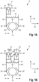
- Fig. 1A shows a first embodiment of an end effector 10 for handling objects 40, 42 in an isolator.
- the end effector 10 has a first receptacle 12 for receiving and gripping a first object 40 and a second receptacle 14 for receiving and gripping a second object 42.
- the first object 40 is smaller than the second object 42.
- the objects 40, 42 are cylindrical.
- the first object 40 has a smaller diameter than the second object 42.
- the objects 40, 42 can be, for example, vials, bottles, syringes, cylinder ampoules, filling needles, a filling needle holder, Petri dishes or agar plates.
- the first object 40 can be a vial, a bottle, a syringe, a cylinder ampoules, filling needles or a filling needle holder, in particular a tangible projection of a filling needle holder.
- the second object 42 can be a Petri dish or an agar plate.
- the first receptacle 12 and the second receptacle 14 are arranged on opposite sides of the end effector 10 in a longitudinal direction 22.
- Each receptacle 12, 14 has an opening in the longitudinal direction 22 which are oriented opposite to one another. Each opening points away from the end effector.
- Each receptacle 12, 14 has a first gripping section 26 and a second gripping section 28.
- the first gripping section 26 and the second gripping section 28 are arranged opposite one another in a transverse direction 24.
- the first object 40 can be arranged between the first gripping section 26 and the second gripping section 28 of the first receptacle 12.
- the second object 42 can be arranged between the first gripping section 26 and the second gripping section 28 of the second receptacle 14.
- the first receptacle 12 and the second receptacle 14 are of different sizes.
- the first receptacle 12 is smaller than the second receptacle 14.
- the distance between the first and second gripping sections 26, 28 of the first receptacle 12 is smaller than the distance between the first and second gripping sections 26, 28 of the second receptacle 14.
- the first receptacle 12 is thus designed for receiving and gripping the smaller first object 12, whereas the second receptacle is suitable for receiving and gripping the larger, second object 42.
- the end effector 10 further comprises a displacement element 16.
- the displacement element 16 comprises the first gripping section 26 of the first receptacle 12 at a first end 30. In particular, the displacement element 16 can form the first gripping section 26 of the first receptacle 12 at the first end 30.
- the displacement element 16 comprises the first gripping section 26 of the second receptacle 14 at a second, opposite end 32. In particular, the displacement element 16 can form the first gripping section 26 of the second receptacle 14 at the second end 32.
- the displacement element 16 thus extends from the first receptacle 12 to the second receptacle 14.
- the end effector 10 further comprises a first bearing element 18.
- the first bearing element 18 is rigidly arranged or attached to the end effector 10.
- the first bearing element 18 extends to the first receptacle 12.
- the second gripping section 28 of the first receptacle 12 is arranged at one end 34 of the first bearing element 18.
- the end effector 10 further comprises a second bearing element 20.
- the second bearing element 20 is rigidly arranged or attached to the end effector 10.
- the second bearing element 20 extends to the second receptacle 14.
- the second gripping section 28 of the second receptacle 14 is arranged at one end 36 of the second bearing element 20.
- the displacement element 16 is arranged displaceably on the end effector.
- the displacement element 16 is displaceable in particular such that the first receptacle 12 and the second receptacle 14 can each be displaced between a receiving position 44 and a gripping position 46.
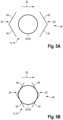
- the receiving position 44 is in Fig. 5A
- the gripping position 46 is Fig. 5B shown.
- the gripping sections 26, 28 are arranged such that the corresponding object 40, 42 can be picked up or introduced between the gripping sections 26, 28.
- the distance between the gripping sections 26, 28 is so large that the corresponding object 40, 42 can be picked up or introduced between the gripping sections 26, 28.
- the distance between the gripping sections 26, 28 is larger than the diameter of the respective object 40, 42.
- the gripping sections 26, 28 are arranged such that the corresponding object 40, 42 can be gripped.
- the distance between the gripping sections 26, 28 is smaller than in the receiving position 44.
- the distance between the gripping sections 26, 28 is so small that the gripping sections 26, 28 rest on both sides of the corresponding object 40, 42 and hold or clamp it between them.
- the gripping sections 26, 28 can each be designed as a recess at the ends of the corresponding elements 16, 18, 20. Each recess has a first edge section 48 and a second, opposite edge section 50. In the gripping position 46, the corresponding object 40, 42 rests at least on the first edge section 48 and the second edge section 50.
- a depth of the gripping sections 26, 28 of the first receptacle 12 designed as a recess is smaller than half the diameter of the first object 40 in the transverse direction 24.
- a depth of the gripping sections 26, 28 of the second receptacle 14 designed as a recess is smaller than half the diameter of the second object 42 in the transverse direction 24.
- a depth of the recesses can also be deeper than half the diameter of the corresponding object if the object rests against the edge sections in such a way that it protrudes into the recess by less than half the diameter of the corresponding object.
- the displacement element 16 can be displaced translationally in the transverse direction 24.
- the end effector can, for example, have a drive device which is designed to move the displacement element 16 in the transverse direction 24.
- the bearing element 18 and the bearing element 20 are arranged on the same side of the displacement element 16 in the transverse direction 24. Accordingly, the first gripping sections 26, 28 of the first and second receptacles 12, 14 are also arranged on the same side of the displacement element 16 in the transverse direction 24. In other words, the first and second receptacles 12, 14 are arranged on the same side of the displacement element 16 in the transverse direction 24.
- each receptacle 12, 14 increases or decreases in size to the same extent.
- the receptacles 12, 14 are displaced together between the receiving position 44 and the gripping position 46.
- the displacement element 16 can be displaced in such a way that when the first receptacle 12 is arranged in the receiving position 44, the second receptacle 14 is also arranged in the receiving position 44 and when the first receptacle 12 is arranged in the gripping position 46, the second receptacle 14 is also arranged in the gripping position 46.
- the end effector 10 can further comprise a first spring element 19.
- the first spring element 19 is designed to pre-tension the first receptacle 12 in the gripping position 46.
- the first spring element 19 is arranged between the displacement element 16 and the bearing element 18.
- the end effector 10 can further comprise a second spring element 21.
- the second spring element 21 is designed to preload the second receptacle 14 in the gripping position 46.
- the second spring element 19 is arranged between the displacement element 16 and the bearing element 20 for this purpose.
- both receptacles 12, 14 can be preloaded together in the gripping position.
- Fig. 1B shows a second embodiment of an end effector 10 for handling objects 40', 40", 42 in an isolator.
- the end effector 10 of the second embodiment has a similar structure to the end effector 10 of the first embodiment. Identical elements are identified by the same reference numerals and are not explained further.
- the end effector 10 of the second embodiment differs from the end effector 10 of the first embodiment in that the end effector 10 of the second embodiment has two first receptacles 12', 12", two displacement elements 16', 16", two first bearing elements 18', 18", but no second bearing element 20.
- the first receptacles 12', 12" are each designed to receive and grip a first object 40', 40".
- the first objects 40', 40" are preferably the same.
- Each receptacle 12', 12", 14 also has a first and a second gripping section 26, 28.
- the bearing elements 18', 18" are designed to correspond to the bearing element 18.
- the displacement elements 16', 16" are designed to correspond to the displacement element 16.
- the displacement element 16' has the first gripping portion 26 of the receptacle 12' at a first end 30'.
- the displacement element 16' has the first gripping portion 26 of the receptacle 14 at a second, opposite end 32'.
- the displacement element 16" has the first gripping portion 26 of the receptacle 12" at a first end 30".
- the displacement element 16" has the second gripping portion 28 of the receptacle 14 at a second, opposite end 32".
- the bearing element 18' has the second gripping section 28 of the receptacle 12' at one end 34'.
- the bearing element 18" has the second gripping section 28 of the receptacle 12" at one end 34".
- the receptacles 12' and 12" are spaced apart from one another in the transverse direction 24.
- the receptacles 12' and 12" are arranged at substantially the same height in the longitudinal direction 22. Accordingly, the displacement elements 16', 16" are spaced apart from one another in the transverse direction 24.
- the bearing elements 18' and 18" are also spaced apart from one another in the transverse direction 24.
- the bearing elements 18' and 18" are arranged between the displacement elements 16', 16". Accordingly, the receptacles 12' and 14 are in the transverse direction 24 on the same side of the displacement element 16' and the receptacles 12" and 14 are arranged in the transverse direction 24 on the same side of the displacement element 16".
- the bearing elements 18' and 18" can basically be arranged rigidly or movably on the end effector 10. In the Fig. 1B In the embodiment shown, the bearing elements 18' and 18" are rigidly, i.e. firmly, attached to the end effector.
- the displacement elements 16', 16" can be displaced translationally in the transverse direction 24.
- the end effector can each have a drive device that is designed to displace the corresponding displacement element 16', 16" in the transverse direction 24.
- only one drive device can be provided that can displace both displacement elements 16', 16" in the transverse direction 24.
- the drive devices are preferably controlled in such a way that the displacement elements 16', 16" are displaced in opposite directions. In other words, the displacement elements 16', 16" are moved either towards or away from each other in the transverse direction 24 by means of the drive devices.
- each receptacle 12', 12", 14 is displaced into the gripping position 46. If the displacement elements 16' and 16" are displaced away from one another in the transverse direction 24, each receptacle 12', 12", 14 is displaced into the gripping position 44.
- the displacement elements 16' and 16" are displaceable in such a way that when the first receptacle 12', 12" is arranged in the gripping position 44, the second receptacle 14 is also arranged in the gripping position 44 and when the first receptacle 12', 12" is arranged in the gripping position 46, the second receptacle 14 is also arranged in the gripping position 46.
- the end effector 10 can further comprise one or two first spring elements 19', 19".
- the first spring elements 19', 19" are each designed to pre-tension one of the first receptacles 12', 12" in the gripping position 46.
- the first spring elements 19', 19" are each arranged between the corresponding displacement element 16', 16" and the corresponding first bearing element 18', 18".
- the end effector 10 can further comprise a second spring element 21.
- the second spring element 21 is designed to pre-tension the second receptacle 14 in the gripping position 46.
- the second spring element 19 is arranged between the first displacement element 16' and the second displacement element 16".
- all receptacles 12', 12", 14 can be preloaded together in the gripping position 46.
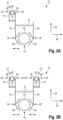
- Fig. 2A shows a third embodiment of an end effector 10 for handling objects 40, 42 in an isolator.
- the end effector 10 of the third embodiment essentially corresponds to the end effector 10 of the first embodiment. Identical elements are identified by the same reference numerals and are not explained further.
- the end effector 10 of the third embodiment differs from the end effector 10 of the first embodiment in that the first bearing element 18 and the bearing element 20 are arranged on opposite sides of the displacement element 16 in the transverse direction 24. Accordingly, the first gripping sections 26, 28 of the first and second receptacles 12, 14 are also arranged on opposite sides of the displacement element 16 in the transverse direction 24. In other words, the first and second receptacles 12, 14 are arranged on opposite sides of the displacement element 16 in the transverse direction 24.
- the displacement element 16 of the end effector 10 of the third embodiment can also be displaced translationally in the transverse direction 22. If the displacement element 16 is displaced in the transverse direction 24, each receptacle 12, 14 is alternately enlarged or reduced in size. As a result, the receptacles 12, 14 are alternately displaced between the receiving position 44 and the gripping position 46. In other words, the displacement element 16 can be displaced such that when the first receptacle 12 is arranged in the receiving position 44, the second receptacle 14 is arranged in the gripping position 46 and when the first receptacle 12 is arranged in the gripping position 46, the second receptacle 14 is also arranged in the receiving position 44.
- the end effector 10 of the third embodiment has either the first spring element 19 for preloading the first receptacle 12 into the gripping position 46 or the second spring element 21 for preloading the second receptacle 14 into the gripping position 46.
- Fig. 2B shows a fourth embodiment of an end effector 10 for handling objects 40', 40", 42 in an isolator.
- the end effector 10 of the fourth embodiment corresponds essentially to the end effector 10 of the second embodiment.
- the same elements are identified by the same reference numerals and are not explained in more detail.
- the end effector 10 of the fourth embodiment differs from the end effector 10 of the second embodiment in that the second receptacle 14 is arranged between the displacement elements 16', 16", while each first receptacle 12', 12" is arranged on the side of the corresponding displacement element 16', 16" facing away from the second receptacle 14.
- the receptacles 12', 12" are displaced into the receiving position 44, while the receptacle 14 is displaced into the gripping position 46. If the displacement elements 16' and 16" are displaced away from one another in the transverse direction 24, the receptacles 12', 12" are displaced into the gripping position 46, while the second receptacle 14 is displaced into the receiving position 44.
- the displacement elements 16' and 16" are displaceable such that when the first receptacles 12', 12" are arranged in the receiving position 44, the second receptacle 14 is arranged in the gripping position and when the first receptacles 12', 12" are arranged in the gripping position 46, the second receptacle 14 is arranged in the receiving position 44.
- the end effector 10 of the fourth embodiment has either the first spring elements 19', 19" for pre-tensioning the first receptacles 12', 12" into the gripping position 46 or the second spring element 21 for pre-tensioning the second receptacle 14 into the gripping position 46.
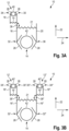
- Fig. 3A shows a fifth embodiment of an end effector 10 for handling objects 40, 42 in an isolator.
- the end effector 10 of the fifth embodiment corresponds essentially to the end effector 10 of the third embodiment. Identical elements are identified by the same reference numerals and are not explained further.
- the end effector 10 of the fifth embodiment differs from the end effector of the third embodiment in that the displacement element 16 of the end effector 10 of the fifth embodiment is rotatably displaceable about an axis of rotation 38.
- the axis of rotation 38 is arranged perpendicular to the longitudinal direction 22 and perpendicular to the transverse direction 24.
- the axis of rotation 38 is arranged between the first end 30 and the second end 32 of the displacement element 16.
- each receptacle 12, 14 increases or decreases simultaneously.
- the receptacles 12, 14 are displaced together between the receiving position 44 and the gripping position 46.
- the displacement element 16 can be displaced in such a way that when the first receptacle 12 is arranged in the receiving position 44, the second receptacle 14 is also arranged in the receiving position 44 and when the first receptacle 12 is arranged in the gripping position 46, the second receptacle 14 is also arranged in the gripping position 46.
- the end effector of the fifth embodiment can have the first spring element 19 and/or the second spring element 21.
- first and/or the second spring element 19, 21 both receptacles 12, 14 can be preloaded together in the gripping position.
- Fig. 3B shows a sixth embodiment of an end effector 10 for handling objects 40', 40", 42 in an isolator.
- the end effector 10 of the sixth embodiment corresponds essentially to the end effector 10 of the fourth embodiment. Identical elements are identified by the same reference numerals and are not explained in more detail.
- the end effector 10 of the sixth embodiment differs from the end effector 10 of the fourth embodiment in that the displacement elements 16', 16" of the end effector 10 of the sixth embodiment can be displaced in a rotational manner about a first axis of rotation 38', 38".
- the first axes of rotation 38', 38" are arranged parallel to one another and are each arranged perpendicular to the longitudinal direction 22 and perpendicular to the transverse direction 24.
- Each axis of rotation 38', 38" is between the first End 30', 30" and the second end 32', 32" of the corresponding displacement element 16', 16".
- the respective drive devices are designed to rotate the corresponding displacement element 16', 16" in opposite directions about the rotation axes 38', 38".
- the first ends 30', 30" and the second ends 32', 32" are either pivoted towards or away from each other.
- the displacement elements 16' and 16" are rotated about rotation axes 38', 38" such that the second ends 32', 32" are pivoted towards one another, the receptacles 12', 12" are displaced into the gripping position 46, while the receptacle 14 is also displaced into the gripping position 46. If the displacement elements 16' and 16" are rotated about rotation axes 38', 38" such that the second ends 32', 32" are pivoted away from one another, the receptacles 12', 12" are displaced into the receptacle position 44, while the second receptacle 14 is also displaced into the receptacle position 44.
- the displacement elements 16' and 16" are displaceable such that when the first receptacles 12', 12" are arranged in the receiving position 44, the second receptacle 14 is arranged in the receiving position 44 and when the first receptacles 12', 12" are arranged in the gripping position 46, the second receptacle 14 is also arranged in the gripping position 46.
- the end effector of the sixth embodiment can have the first spring elements 19', 19" and/or the second spring element 21.
- first spring elements 19', 19" and/or the second spring element 21 By means of the first spring elements 19', 19" and/or the second spring element 21, all receptacles 12', 12", 14 can be preloaded together in the gripping position 46.
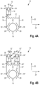
- Fig. 4A shows a seventh embodiment of an end effector 10 for handling objects 40, 42 in an isolator.
- the end effector 10 of the seventh embodiment corresponds essentially to the end effector 10 of the first embodiment.
- the same elements are identified by the same reference numerals and are not explained further.
- the end effector 10 of the seventh embodiment differs from the end effector of the first embodiment in that the displacement element 16 is rotatably displaceable about the axis of rotation 38.
- the axis of rotation 38 is arranged perpendicular to the longitudinal direction 22 and perpendicular to the transverse direction 24.
- the axis of rotation 38 is between the first end 30 and the second end 32 of the displacement element 16.
- each receptacle 12, 14 is alternately enlarged or reduced in size.
- the receptacles 12, 14 are alternately displaced between the receiving position 44 and the gripping position 46.
- the displacement element 16 can be displaced in such a way that when the first receptacle 12 is arranged in the receiving position 44, the second receptacle 14 is arranged in the gripping position 46 and when the first receptacle 12 is arranged in the gripping position 46, the second receptacle 14 is also arranged in the receiving position 44.
- the end effector 10 of the third embodiment has either the first spring element 19 for preloading the first receptacle 12 into the gripping position 46 or the second spring element 21 for preloading the second receptacle 14 into the gripping position 46.
- Fig. 4B shows an eighth embodiment of an end effector 10 for handling objects 40', 40", 42 in an isolator.
- the end effector 10 of the eighth embodiment essentially corresponds to the end effector 10 of the second embodiment.
- the same elements are identified by the same reference numerals and are not explained in more detail.
- the end effector 10 of the eighth embodiment differs from the end effector 10 of the second embodiment in that the displacement elements 16', 16" of the end effector 10 of the eighth embodiment can be displaced in a rotational manner about a rotation axis 38', 38".
- the rotation axes 38', 38" are arranged parallel to one another and are each arranged perpendicular to the longitudinal direction 22 and perpendicular to the transverse direction 24.
- Each rotation axis 38', 38" is arranged between the first end 30', 30" and the second end 32', 32" of the corresponding displacement element 16', 16".
- the respective drive devices are designed to rotate the corresponding displacement element 16', 16" in opposite directions of rotation about the rotation axes 38', 38".
- the first ends 30', 30" and the second ends 32', 32" are either pivoted towards or away from each other.
- the displacement elements 16' and 16" are rotated about rotation axes 38', 38" such that the second ends 32', 32" are pivoted towards one another, the receptacles 12', 12" are displaced into the receiving position 44, while the receptacle 14 is displaced into the gripping position 46. If the displacement elements 16' and 16" are rotated about rotation axes 38', 38" such that the second ends 32', 32" are pivoted away from one another, the receptacles 12', 12" are displaced into the gripping position 46, while the second receptacle 14 is displaced into the receiving position 44.
- the displacement elements 16' and 16" are displaceable such that when the first receptacles 12', 12" are arranged in the receiving position 44, the second receptacle 14 is arranged in the gripping position and when the first receptacles 12', 12" are arranged in the gripping position 46, the second receptacle 14 is also arranged in the receiving position 44.
- the end effector 10 of the fourth embodiment has either the first spring elements 19', 19" for pre-tensioning the first receptacles 12', 12" into the gripping position 46 or the second spring element 21 for pre-tensioning the second receptacle 14 into the gripping position 46.
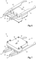
- the Figures 6 to 10 show a ninth embodiment of an end effector 10 for handling objects 40', 40", 42 in an isolator.
- the end effector 10 of the ninth embodiment corresponds essentially to the end effector 10 of the eighth embodiment.
- the same elements are identified by the same reference numerals and are not explained in more detail.
- the end effector 10 of the ninth embodiment differs from the end effector 10 of the eighth embodiment in that the bearing elements 18' and 18" are each mounted on the end effector 10 so as to be rotatable about a second axis of rotation 80', 80", wherein the second axes of rotation 80', 80" are arranged parallel to the first axes of rotation 38', 38".
- the ninth embodiment shows in detail how the displacement elements 16', 16" and the bearing elements 18', 18" can be moved in a coupled manner.
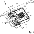
- the end effector 10 of the ninth embodiment further comprises a first drive device 62 which is designed to move the displacement element 16' and the bearing element 18'.
- the end effector 10 further comprises a second Drive device 64 which is designed to move the displacement element 16" and the bearing element 18".
- the end effector 10 has a drive device 62, 64 for displacing one of the displacement elements 16', 16" and one of the bearing elements 18', 18".
- Each drive device 62, 64 is designed to rotate the corresponding displacement element 16', 16" about the respective first axis of rotation 38', 38" and to rotate the corresponding bearing element 18', 18" about the respective second axis of rotation 80', 80".
- the first drive device 62 has a first drive shaft 72, by means of which the displacement element 16' and the bearing element 18' are driven.
- the second drive device 64 has a second drive shaft 74, by means of which the displacement element 16" and the bearing element 18" are driven.
- the longitudinal axes of the drive shafts 72, 74 are arranged parallel to one another and perpendicular to the first and second axes of rotation 38', 38", 80', 80".
- the longitudinal axes of the drive shafts 72, 74 can be arranged parallel to the longitudinal direction 22.
- the end effector 10 can further comprise a distribution device 66.
- the distribution device 66 can be designed to supply the electronic components of the end effector 10 with electrical energy (operating voltage) and/or to provide the electronic components of the end effector 10 with control signals from a control device.
- the distribution device 66 can comprise a plurality of terminals for signal lines and/or power lines.
- the end effector 10 can further comprise a storage device for storing electrical energy.
- the storage device can be a battery or an accumulator, for example.
- the drive devices 62, 64 can be electrically coupled to the storage device.
- the drive devices 62, 64 can be electrically connected to the storage device, for example, via the distribution device 66.
- the distribution device 66 can also comprise the storage device.
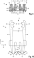
- the end effector 10 has a corresponding first coupling element 68 for each displacement element 16', 16".
- Each first coupling element 68 is rotationally fixed to the corresponding displacement element 16', 16".
- Each first coupling element 68 is rotatably mounted about the corresponding first axis of rotation 38', 38".
- each displacement element 16', 16" is rotatably mounted on the end effector 10 about the respective first axis of rotation 38', 38" by means of the corresponding first coupling element 68.
- Each first coupling element 68 is coupled to the corresponding drive shaft 72, 74.
- each first coupling element 68 has a first toothed section 76 which is in engagement with the corresponding drive shaft 72, 74.
- each drive shaft 72, 74 may have a thread and each first toothing section 76 may have teeth distributed in a circumferential direction about the respective first axis of rotation 38', 38", wherein the thread of each drive shaft 72, 74 engages with the teeth of the corresponding first toothing section 76. If the drive shafts 72, 74 are rotated about the respective longitudinal axes, the corresponding coupling elements 68 and thereby also the corresponding displacement elements 16', 16" are rotated about the respective first axis of rotation 38', 38".
- the end effector 10 has a corresponding second coupling element 70 for each bearing element 18', 18".
- Each second coupling element 70 is connected in a rotationally fixed manner to the corresponding bearing element 18', 18".
- Each second coupling element 70 is rotatably mounted about the corresponding second axis of rotation 80', 80".
- each bearing element 18', 18" is rotatably mounted on the end effector 10 about the respective second axis of rotation 80', 80" by means of the corresponding second coupling element 70.
- Each second coupling element 70 is coupled to the corresponding drive shaft 72, 74.
- each second coupling element 70 has a second toothed section 78 which engages with the corresponding drive shaft 72, 74.
- each second toothed section 78 can have teeth which are distributed in a circumferential direction about the respective second axis of rotation 80', 80", wherein the thread of each drive shaft 72, 74 engages with the teeth of the corresponding second toothed section 78. If the drive shafts 72, 74 are rotated about the respective longitudinal axes, the corresponding second coupling elements 70 and thereby also the corresponding bearing elements 18', 18" are rotated about the respective second axis of rotation 80', 80".
- first coupling element 68 and a second coupling element 70 are each engaged with a drive shaft 72, 74, when one of the drive shafts 72, 74 rotates, both the first coupling element 68 and the second coupling element 70 are rotated about the corresponding first axis of rotation or second axis of rotation 38', 38", 80', 80".
- the rotational movements of each displacement element 16', 16" and the corresponding bearing element 18', 18" are coupled to one another.
- the respective drive shaft 72, 74 is arranged between the corresponding first and second coupling elements 68, 70.
- the first coupling element 68 and the second coupling element 70 are rotated in opposite directions of rotation, so that the gripping sections 26, 28 of the respective first receptacles 12', 12" are moved towards or away from each other.
- the end effector 10 has a housing 82.
- the housing 82 has a top side 54 and a bottom side 56.
- the drive devices 62, 64 and the distributor device 66 are arranged in the housing 82.
- the displacement elements 16', 16" and the bearing elements 18', 18" are arranged outside the housing 82 on the top side 54.
- the coupling elements 68, 70 extend from the corresponding displacement elements 16', 16" and bearing elements 18', 18" into the housing.
- the housing has four corresponding holes on the top side through which the coupling elements 68, 70 are introduced into the housing.
- the housing also has a bore 58 on the underside 56.
- a bearing 60 is arranged inside the housing and is aligned with the bore.
- a bearing element of a robot can be guided through the bore 58 from the outside and coupled to the bearing 60 in order to rotatably mount the end effector 10 on the robot.
- An axis of rotation of this bearing is preferably parallel to the first and second axes of rotation 38', 38", 80', 80".
- Signal lines and/or control lines can be introduced into the housing through the hole 58.
- the signal lines and/or control lines can be coupled, for example, to the distribution device 66.
- the signal lines and/or control lines can also be connected directly to the electronic components of the end effector, for example, the drive devices 62, 64, in order to control the electronic components and supply them with electrical energy.
- the gripping sections 26, 28 of the first receptacles 12', 12" are designed as V-shaped recesses and each have a first edge section 48 and a second edge section 50 which adjoin one another and are arranged at an angle to one another.
- the first and second edge sections 48, 50 adjoin one another in particular at the lowest point of the recess.
- the gripping sections 26, 28 of the second receptacle 14 are designed as a recess and each have a first edge section 48, a second edge section 50 and an intermediate section 52 which is arranged between the first and the second edge section 48, 50.
- the first and second edge sections 48, 50 are arranged at an angle to one another.
- the intermediate section 52 forms in particular the deepest section of the recess, wherein the depth of the recess remains the same along the intermediate section 52.
- FIG. 11 The arrangement of two first objects 40', 40" in the first receptacles 12', 12" is shown as an example.
- the first objects 40', 40" in this case are two identically designed bottles. Accordingly, vials, carpules, syringes and/or cylinder ampoules can also be arranged in the first receptacles 12', 12".
- a second object 42 in the second receptacle 14 is shown as an example.
- the second object 42 in this case is an agar plate or Petri dish.
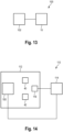
- Fig. 13 shows an embodiment of a robot 100 for handling objects in an isolator.
- the robot has an end effector 10 and a support structure 102 for supporting the end effector 10.
- the end effector 10 can be designed according to one of the Figures 1 to 12 described embodiments.
- the robot 100 is designed to move and align the end effector 10 in the isolator.
- the support structure 102 can be designed to be articulated.
- the support structure 102 can, for example, have several arms that are coupled to one another via joints.
- the support structure 102 of the robot 100 can be designed to be movable in such a way that the end effector 10 in the isolator can be moved by means of the robot 100.
- the robot 100 can, for example, have one or more drive devices.
- the end effector can be rotatably mounted at one end of the support structure. In this way, the receptacles 12, 14 of the end effector 10 in the isolator can be aligned with respect to the objects 40, 42 to be picked up.
- the robot 100 can also have a further drive device for rotating the end effector 10.
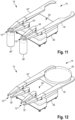
- Fig. 14 shows an embodiment of a system 110 for handling objects 40, 42 in an isolator 112.
- the system comprises the isolator 112 and a robot 100.
- the robot 100 can be operated in accordance with the Figures 13 described embodiment.
- a first object 40 and/or a second object 42 can be arranged in the insulator 112.
- the system further comprises a control device 114.
- the control device 114 is designed to control the movement of the end effector 10 and/or the robot 100.
- the control device 114 can, for example, control at least one drive device of the end effector 10 in order to move the receptacles 12, 14 between the receiving position 44 and the gripping position 46.
- the control device 114 can, for example, send control signals to the drive devices 62, 64 of the end effector.
- control device 114 can control the robot 100 to move and align the end effector 10 in the isolator 112.
- the control device 114 can, for example, send control signals to the corresponding drive devices of the robot 100.
- the system can further comprise a sensor device 116.
- the sensor device 116 is designed to detect the position and orientation of the end effector 10 and the objects 40, 42 in the isolator 112.
- the sensor device 116 sends sensor signals to the control device 114, wherein the sensor signals contain information about the detected position and orientation of the end effector 10 and the objects 40, 42 in the isolator 112.
- the control device 114 is designed to control the robot 100 and the end effector 10 based on the sensor signals.
- the control device 114 controls the end effector 10 such that the first receptacle 12 is arranged in the receiving position 44 or is moved into it.
- the control device 114 controls the robot 100 such that the end effector 10 in the isolator 112 is moved to the position of the first object 40.
- the end effector 10 will be moved such that the first object 40 can be received in the first receptacle 12.
- the end effector 10 in the isolator 112 is moved and aligned such that the first object 40 is arranged in the first receptacle 12.
- the control device 114 controls the end effector 10 such that the first receptacle 12 is displaced into the gripping position 46 in order to grip the first object 40.
- the control device 114 then controls the robot 100 such that the robot 100 further moves the end effector 10 in the isolator 112, whereby the first object 40 gripped in the first receptacle 12 can be transferred to a target position in the isolator 112.
- control device 114 controls the end effector 10 such that the first holder 12 is moved from the gripping position 46 to the receiving position 44 in order to release the first object 40 again.
- the second object 42 can also be received, gripped, transferred and released again in the second holder 14 in a corresponding manner.
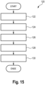
- Fig. 15 shows an embodiment of a method 120 for handling objects 40, 42 in the isolator 112.
- the method can be derived from the previously described system 110 Fig. 14 be executed.
- the first receptacle 12 or the second receptacle 14 is arranged in the receiving position 44 in which the first object 40 or second object 42 can be received in the corresponding receptacle 12, 14. If the end effector 10 has two first receptacles 12', 12", both first receptacles 12', 12" are arranged in the receiving position 44.
- the respective object 40, 42 is recorded in the corresponding recording 12, 14. If the end effector 10 has two first recordings 12', 12", a first object 40', 40" can be recorded in each first recording 12', 12".
- the respective object 40, 42 is gripped by displacing the displacement element 16 such that the corresponding receptacle 12, 14 is displaced from the receiving position 44 into the gripping position 46 in which the respective object 40, 42 can be gripped. If the end effector 10 has two first receptacles 12', 12", the two displacement elements 16', 16" are displaced such that the first receptacle 12', 12" or the second receptacle 14 is displaced from the receiving position 44 into the gripping position 46, depending on whether two first objects 40', 40" or a second object 42 are to be gripped.
- the respective object 40, 42 is handled by moving the end effector 10 by means of the robot 100 in the isolator 112 while the respective object 40, 42 is gripped.
- the end effector 10 can be moved and aligned in the isolator 112 such that the respective object 40, 42 is transferred to a target position.
- the respective object 40, 42 is released again by displacing the displacement element 16 such that the corresponding receptacle 12, 14 is displaced from the gripping position 46 to the receiving position 44. If the end effector 10 has two first receptacles 12', 12", the two displacement elements 16', 16" are displaced such that the first receptacle 12', 12" or the second receptacle 14 is displaced from the gripping position 46 to the receiving position 44, depending on whether two first objects 40', 40" or a second object 42 are to be released.
Landscapes
- Engineering & Computer Science (AREA)
- Robotics (AREA)
- Mechanical Engineering (AREA)
- Manipulator (AREA)
Description
Die vorliegende Erfindung betrifft einen Endeffektor, einen Roboter, ein System und ein Verfahren zum Handhaben von Objekten in einem Isolator.The present invention relates to an end effector, a robot, a system and a method for handling objects in an isolator.
Derartige Endeffektoren, Roboter, Systeme und Verfahren zum Handhaben von Objekten in einem Isolator sind im Stand der Technik allgemein bekannt.Such end effectors, robots, systems and methods for handling objects in an isolator are well known in the art.
Beispielsweise können zum Handhaben unterschiedlicher Objekte verschiedene Endeffektoren eingesetzt werden, die zum Handhaben des jeweiligen Objekttyps geeignet sind. Des Weiteren sind auch Endeffektoren bekannt, die zum Handhaben von verschiedenen Objekttypen geeignet sind. Diese Endeffektoren weisen beispielsweise mehrere Werkzeuge oder ein Multifunktionswerkzeug zum Handhaben der verschiedenen Objekttypen auf.For example, different end effectors can be used to handle different objects, which are suitable for handling the respective object type. Furthermore, end effectors are also known that are suitable for handling different object types. These end effectors have, for example, several tools or a multi-function tool for handling the different object types.
Beispielsweise zeigt die Druckschrift
Des Weiteren zeigt die Druckschrift
Des Weiteren zeigt die Druckschrift
Des Weiteren zeigt die Druckschrift
Die bekannten Endeffektoren, Roboter, Systeme und Verfahren zum Handhaben von Objekten in einem Isolator lassen aber noch Raum für Verbesserungen.However, the known end effectors, robots, systems and methods for handling objects in an isolator still leave room for improvement.
Es ist daher eine Aufgabe der vorliegenden Erfindung, einen verbesserten Endeffektor, einen verbesserten Roboter, ein verbessertes System und ein verbessertes Verfahren zum Handhaben von Objekten in einem Isolator bereitzustellen.It is therefore an object of the present invention to provide an improved end effector, an improved robot, an improved system and an improved method for handling objects in an isolator.
Des Weiteren ist es eine Aufgabe der vorliegenden Erfindung, verschiedene Objekte innerhalb eines Isolators auf möglichst einfache Art und Weise zu handhaben.Furthermore, it is an object of the present invention to handle various objects within an isolator in the simplest possible manner.
Des Weiteren ist es eine Aufgabe der vorliegenden Erfindung, einen Endeffektor zum Handhaben von Objekten in einem Isolator bereitzustellen, der einen möglichst einfachen Aufbau hat und möglichst einfach zu steuern und zu fertigen ist.Furthermore, it is an object of the present invention to provide an end effector for handling objects in an isolator, which has the simplest possible structure and is as easy to control and manufacture as possible.
Gemäß einem ersten Aspekt der vorliegenden Erfindung ist ein Endeffektor zum Handhaben von Objekten in einem Isolator bereitgestellt. Der Endeffektor weist eine erste Aufnahme für ein erstes Objekt, eine zweite Aufnahme für ein zweites Objekt, und ein erstes Verlagerungselement auf, wobei die Aufnahmen in einer Längsrichtung auf entgegengesetzten Seiten des Endeffektors angeordnet sind, wobei jede Aufnahme zwischen einer Aufnahmestellung, in der das jeweilige Objekt in die entsprechende Aufnahme aufgenommen werden kann, und einer Greifstellung, in der das jeweilige Objekt mit der entsprechenden Aufnahme gegriffen werden kann, verlagerbar ist, wobei jede Aufnahme einen ersten Greifabschnitt aufweist, wobei der erste Greifabschnitt der ersten Aufnahme an einem ersten Ende des Verlagerungselements und der erste Greifabschnitt der zweiten Aufnahme an einem entgegengesetzten, zweiten Ende des Verlagerungselements angeordnet ist, wobei das Verlagerungselement derart verlagerbar ist, dass die erste Aufnahme und die zweite Aufnahme jeweils zwischen der Aufnahmestellung und der Greifstellung verlagert werden können. Der Endeffektor weist zwei erste Aufnahmen und zwei Verlagerungselemente auf, wobei an dem ersten Ende jedes Verlagerungselements der erste Greifabschnitt jeweils einer der ersten Aufnahmen angeordnet ist, wobei an den zweiten, entgegengesetzten Enden der Verlagerungselemente jeweils der erste und der zweite Greifabschnitt der zweiten Aufnahme angeordnet sind.According to a first aspect of the present invention, an end effector for handling objects in an isolator is provided. The end effector comprises a first receptacle for a first object, a second receptacle for a second object, and a first displacement element, wherein the receptacles are arranged in a longitudinal direction on opposite sides of the end effector, wherein each receptacle can be moved between a receiving position in which the respective object can be received in the corresponding receptacle, and a gripping position in which the respective object can be gripped with the corresponding receptacle can be gripped, wherein each receptacle has a first gripping section, wherein the first gripping section of the first receptacle is arranged at a first end of the displacement element and the first gripping section of the second receptacle is arranged at an opposite, second end of the displacement element, wherein the displacement element is displaceable such that the first receptacle and the second receptacle can each be displaced between the receiving position and the gripping position. The end effector has two first receptacles and two displacement elements, wherein the first gripping section of one of the first receptacles is arranged at the first end of each displacement element, wherein the first and second gripping sections of the second receptacle are arranged at the second, opposite ends of the displacement elements.
Gemäß einem zweiten Aspekt der vorliegenden Erfindung ist ein Roboter zum Handhaben von Objekten in einem Isolator bereitgestellt, wobei der Roboter einen Endeffektor nach dem ersten Aspekt der Erfindung aufweist.According to a second aspect of the present invention there is provided a robot for handling objects in an isolator, the robot comprising an end effector according to the first aspect of the invention.
Gemäß einem dritten Aspekt der vorliegenden Erfindung ist ein System mit einem Isolator und einem in dem Isolator angeordneten Roboter nach dem zweiten Aspekt der Erfindung bereitgestellt.According to a third aspect of the present invention, there is provided a system comprising an isolator and a robot according to the second aspect of the invention arranged in the isolator.
Gemäß einem vierten Aspekt der vorliegenden Erfindung Verfahren zum Handhaben von Objekten in einem Isolator bereitgetsellt, wobei in dem Isolator ein Roboter mit einem Endeffektor angeordnet ist, wobei der Endeffektor eine erste Aufnahme für ein erstes Objekt, eine zweite Aufnahme für ein zweites Objekt, und ein erstes Verlagerungselement aufweist, wobei die Aufnahmen in einer Längsrichtung auf entgegengesetzten Seiten des Endeffektors angeordnet sind, wobei jede Aufnahme einen ersten Greifabschnitt aufweist, wobei der erste Greifabschnitt der ersten Aufnahme an einem ersten Ende des Verlagerungselements und der erste Greifabschnitt der zweiten Aufnahme an einem entgegengesetzten, zweiten Ende des Verlagerungselements angeordnet ist, wobei das Verlagerungselement verlagerbar ist, wobei der Endeffektor zwei erste Aufnahmen und zwei Verlagerungselemente aufweist, wobei an dem ersten Ende jedes Verlagerungselements der erste Greifabschnitt jeweils einer der ersten Aufnahmen angeordnet ist, wobei an den zweiten, entgegengesetzten Enden der Verlagerungselemente jeweils der erste und der zweite Greifabschnitt der zweiten Aufnahme angeordnet sind, wobei das Verfahren die folgenden Schritte aufweist:
- Anordnen der ersten Aufnahme oder der zweiten Aufnahme in einer Aufnahmestellung, in der das erste Objekt oder das zweite Objekt in der entsprechenden Aufnahme aufgenommen werden kann;
- Aufnehmen des jeweiligen Objekts in der entsprechenden Aufnahme; und
- Greifen des jeweiligen Objekts, indem das Verlagerungselement derart verlagert wird, dass die entsprechende Aufnahme von der Aufnahmestellung in eine Greifstellung verlagert wird, in der das jeweilige Objekt gegriffen werden kann.
- Arranging the first shot or the second shot in a shooting position in which the first object or the second object can be recorded in the corresponding shot;
- Recording the respective object in the corresponding recording; and
- Gripping the respective object by displacing the displacement element in such a way that the corresponding holder is displaced from the holding position into a gripping position in which the respective object can be gripped.
Die zu handhabenden Objekte können beispielsweise Vials, Karpulen, Flaschen, Spritzen, Zylinderampullen, Füllnadeln, ein Füllnadelhalter, Petrischalen, Agar-Platten und/oder dergleichen sein. Das erste Objekt ist vorzugsweise ein Vial, eine Flasche, eine Spritze, eine Zylinderampullen, Füllnadeln oder ein Füllnadelhalter, insbesondere ein greifbarer Vorsprung eines Füllnadelhalters, sein. Das zweite Objekt ist vorzugsweise eine Petrischale oder eine Agar-Platte.The objects to be handled can be, for example, vials, cartridges, bottles, syringes, cylinder ampoules, filling needles, a filling needle holder, Petri dishes, agar plates and/or the like. The first object is preferably a vial, a bottle, a syringe, a cylinder ampoules, filling needles or a filling needle holder, in particular a tangible projection of a filling needle holder. The second object is preferably a Petri dish or an agar plate.
Unter dem Begriff "Isolator" ist allgemein ein Behälter zu verstehen, der gegenüber dem umgebenden Arbeitsraum hermetisch und gasdicht abgeschlossen ist. Innerhalb eines Isolators kann eine definierte Atmosphäre zur Bearbeitung empfindlicher oder gefährlicher Produkte erzeugt werden. Der Isolator kann vorzugsweise ein aseptischen Isolator sein, der vorzugsweise einen Füllbereich zum fluiden Befüllen von Objekten (z.B. Vials, Karpulen, Fläschchen, Spritzen und/oder dergleichen) mittels Füllnadeln aufweist.The term "isolator" generally refers to a container that is hermetically and gas-tightly sealed from the surrounding work area. A defined atmosphere can be created within an isolator for processing sensitive or dangerous products. The isolator can preferably be an aseptic isolator, which preferably has a filling area for filling objects (e.g. vials, cartridges, bottles, syringes and/or the like) with fluid using filling needles.
Jede Aufnahme weist eine Aufnahmestellung und eine Greifstellung auf und ist zwischen diesen Stellungen verlagerbar. In der Aufnahmestellung ist jede Aufnahme so weit geöffnet, dass die Aufnahme ein entsprechendes Objekt aufnehmen kann. In anderen Worten ist die Aufnahme dabei soweit geöffnet, dass das entsprechende Objekt in die Aufnahme eingebracht werden kann. Die Aufnahmestellung kann somit auch als offene oder geöffnete Stellung bezeichnet werden. In der Greifstellung ist die Aufnahme so weit geschlossen, dass das entsprechende Objekt durch die Aufnahme gegriffen wird. Unter "Greifen" ist hierbei zu verstehen, dass das Objekt in der Aufnahme geklemmt bzw. gehalten ist. Die Greifstellung kann somit auch als geschlossene Stellung bezeichnet werden.Each holder has a holding position and a gripping position and can be moved between these positions. In the holding position, each holder is opened wide enough for the holder to hold a corresponding object. In other words, the holder is opened wide enough for the corresponding object to be inserted into the holder. The holding position can therefore also be used as an open or open position. In the gripping position, the holder is closed so far that the corresponding object is gripped by the holder. "Gripping" here means that the object is clamped or held in the holder. The gripping position can therefore also be referred to as the closed position.
Das erste Verlagerungselement ist verlagerbar. Dies bedeutet, dass das erste Verlagerungselement relativ zu anderen Komponenten des Endeffektors bewegbar ist. In anderen Worten ist das erste Verlagerungselement an dem Endeffektor verlagerbar angeordnet.The first displacement element is displaceable. This means that the first displacement element is movable relative to other components of the end effector. In other words, the first displacement element is arranged displaceably on the end effector.
Des Weiteren koppelt das erste Verlagerungselement die Verlagerung der ersten und zweiten Aufnahme. Dazu erstreckt sich das erste Verlagerungselement von der ersten Aufnahme bis zur zweiten Aufnahme und bildet an seinen Enden die entsprechenden ersten Greifabschnitte der Aufnahmen aus. Wird das erste Verlagerungselement verlagert, so werden auch die Greifabschnitte an den Enden des ersten Verlagerungselements verlagert, so dass die Aufnahmen entweder weiter geöffnet oder weiter geschlossen werden. Dadurch werden auch die Aufnahmen zwischen der Greifstellung und der Aufnahmestellung verlagert.Furthermore, the first displacement element couples the displacement of the first and second receptacles. To do this, the first displacement element extends from the first receptacle to the second receptacle and forms the corresponding first gripping sections of the receptacles at its ends. If the first displacement element is displaced, the gripping sections at the ends of the first displacement element are also displaced so that the receptacles are either opened further or closed further. This also displaces the receptacles between the gripping position and the receptacle position.
Der Endeffektor ist somit als Multifunktionswerkzeug ausgebildet, das zwei Aufnahmen aufweist, mit denen verschiedene Objekte gehandhabt werden können. Durch das verlagern des Verlagerungselements können beide Aufnahmen gleichzeitig verlagert werden. Dadurch ist nur ein Antriebsmittel für das Verlagerungselement erforderlich um beide Aufnahmen zu verlagern.The end effector is thus designed as a multifunctional tool that has two holders with which different objects can be handled. By moving the displacement element, both holders can be moved simultaneously. This means that only one drive means is required for the displacement element to move both holders.
Der Endeffektor weist zwei erste Aufnahmen und zwei Verlagerungselemente auf, wobei an dem ersten Ende jedes Verlagerungselements der erste Greifabschnitt jeweils einer der ersten Aufnahmen angeordnet ist, wobei an den zweiten, entgegengesetzten Enden der Verlagerungselemente jeweils der erste und der zweite Greifabschnitt der zweiten Aufnahme angeordnet sind. Auf diese Weise können mit den ersten Aufnahmen zwei erste Objekte gleichzeitig gegriffen werden. Dies ist insbesondere dann von Vorteil, wenn kleinere erste Objekte, beispielsweise mehrere Vials, Behälter, Füllnadeln und dergleichen, im Isolator gleichzeigt gehandhabt werden sollen. Die zweite Aufnahme ist vorzugsweise zum Handhaben von größeren Objekten ausgebildet, wie beispielsweise Petrischalen oder Agar-Platten die in der Regel einzeln gehandhabt werden.The end effector has two first receptacles and two displacement elements, wherein the first gripping section of one of the first receptacles is arranged at the first end of each displacement element, wherein the first and second gripping sections of the second receptacle are arranged at the second, opposite ends of the displacement elements. In this way, two first objects can be gripped simultaneously with the first receptacles. This is particularly advantageous when Smaller first objects, for example several vials, containers, filling needles and the like, are to be handled simultaneously in the isolator. The second holder is preferably designed for handling larger objects, such as Petri dishes or agar plates, which are usually handled individually.
Der Roboter ist dazu ausgebildet, den Endeffektor im Isolator zu bewegen und auszurichten. Beispielsweise kann im Isolator ein erstes zu handhabendes Objekt angeordnet sein. Die erste Aufnahme in die Aufnahmestellung verlagert bzw. angeordnet werden. Dann kann der Roboter den Endeffektor im Isolator zu der Position des Objekts bewegen. Insbesondere kann der Endeffektor so bewegt werden, dass das erste Objekt in die erste Aufnahme aufgenommen wird. Ist das erste Objekt in der Aufnahme angeordnet, kann die erste Aufnahme in die Greifstellung verlagert werden, um das Objekt zu greifen. Der Roboter kann dann den Endeffektor im Isolator weiter bewegen, wodurch das in der ersten Aufnahme gegriffene erste Objekt im Raum transferiert werden kann. Zum Freigeben des ersten Objekts wird die erste Aufnahme wieder in die Aufnahmestellung verlagert. Entsprechend kann auch das zweite Objekt in der zweiten Aufnahme aufgenommen, gegriffen, transferiert und wieder freigegeben werden.The robot is designed to move and align the end effector in the isolator. For example, a first object to be handled can be arranged in the isolator. The first receptacle can be moved or arranged in the receiving position. The robot can then move the end effector in the isolator to the position of the object. In particular, the end effector can be moved so that the first object is received in the first receptacle. If the first object is arranged in the receptacle, the first receptacle can be moved to the gripping position in order to grip the object. The robot can then move the end effector further in the isolator, whereby the first object gripped in the first receptacle can be transferred in space. To release the first object, the first receptacle is moved back to the receiving position. The second object can also be picked up, gripped, transferred and released again in a similar way in the second receptacle.
Der erfindungsgemäße Endeffektor ermöglicht somit, verschiedene Objekte innerhalb eines Isolators auf möglichst einfache Art und Weise zu handhaben. Zudem weist der erfindungsgemäße Endeffektor einen einfachen Aufbau hat und ist einfach zu steuern und zu fertigen.The end effector according to the invention thus makes it possible to handle various objects within an isolator in the simplest possible way. In addition, the end effector according to the invention has a simple structure and is easy to control and manufacture.
Die eingangs gestellte Aufgabe wird somit vollumfänglich gelöst.The task posed at the beginning is thus completely solved.
In einer ersten Ausgestaltung ist das Verlagerungselement derart verlagerbar, dass, wenn die erste Aufnahme in der Aufnahmestellung angeordnet ist, die zweite Aufnahme in der Greifstellung angeordnet ist und, wenn die zweite Aufnahme in der Aufnahmestellung angeordnet ist, die erste Aufnahme in der Greifstellung angeordnet ist.In a first embodiment, the displacement element is displaceable such that, when the first receptacle is arranged in the receiving position, the second receptacle is arranged in the gripping position and, when the second receptacle is arranged in the receiving position, the first receptacle is arranged in the gripping position.
Dabei werden die erste Aufnahme und die zweite Aufnahme im Wechsel zwischen der Aufnahmestellung und der Greifstellung verlagert. Dazu wird das Verlagerungselement derart verlagert, dass beim Verlagern die eine Aufnahme weiter geöffnet wird, während die andere Aufnahme weiter geschlossen wird.The first holder and the second holder are shifted alternately between the pick-up position and the gripping position. For this purpose, the shifting element shifted in such a way that when shifted, one receptacle opens further while the other receptacle closes further.
In einer weiteren Ausgestaltung ist das Verlagerungselement derart verlagerbar, dass, wenn die erste Aufnahme in der Aufnahmestellung angeordnet ist, die zweite Aufnahme in der Aufnahmestellung angeordnet ist und, wenn die zweite Aufnahme in der Greifstellung angeordnet ist, die erste Aufnahme in der Greifstellung angeordnet ist.In a further embodiment, the displacement element is displaceable such that, when the first receptacle is arranged in the receiving position, the second receptacle is arranged in the receiving position and, when the second receptacle is arranged in the gripping position, the first receptacle is arranged in the gripping position.
Dabei werden die erste Aufnahme und die zweite Aufnahme zusammen zwischen der Aufnahmestellung und der Greifstellung verlagert. Dazu wird das Verlagerungselement derart verlagert, dass beim Verlagern beide Aufnahmen entweder weiter geöffnet oder weiter geschlossen werden.The first holder and the second holder are moved together between the holding position and the gripping position. To do this, the displacement element is moved in such a way that both holders are either opened further or closed further during the movement.
In einer weiteren Ausgestaltung weist jede Aufnahme einen zweiten Greifabschnitt auf, wobei der erste und der zweite Greifabschnitt in einer Querrichtung gegenüberliegend angeordnet sind.In a further embodiment, each receptacle has a second gripping portion, wherein the first and the second gripping portion are arranged opposite one another in a transverse direction.
Der erste und der zweite Greifabschnitt bilden somit zwei Seiten der Aufnahme aus, zwischen denen das entsprechende Objekt in der Greifstellung gegriffen bzw. geklemmt wird. Die Längsrichtung kann insbesondere im Wesentlichen senkrecht zur Querrichtung angeordnet sein.The first and second gripping sections thus form two sides of the holder, between which the corresponding object is gripped or clamped in the gripping position. The longitudinal direction can in particular be arranged essentially perpendicular to the transverse direction.
In einer weiteren Ausgestaltung ist der Abstand zwischen dem ersten und dem zweiten Greifabschnitt in der Aufnahmestellung so groß ist, dass das entsprechende Objekt zwischen den Greifabschnitten aufgenommen werden kann.In a further embodiment, the distance between the first and the second gripping section in the receiving position is so large that the corresponding object can be picked up between the gripping sections.
In anderen Worten kann das entsprechende Objekt in der Aufnahmestellung in die Aufnahme eingebracht bzw. aus der Aufnahme herausgenommen oder herausgeführt werden.In other words, the corresponding object can be inserted into the holder in the holder position or removed or led out of the holder.
In einer weiteren Ausgestaltung ist der Abstand zwischen dem ersten und dem zweiten Greifabschnitt in der Greifstellung so klein ist, dass das entsprechende Objekt zwischen den Greifabschnitten gegriffen werden kann.In a further embodiment, the distance between the first and the second gripping section in the gripping position is so small that the corresponding object can be gripped between the gripping sections.
In anderen Worten wird das entsprechende Objekt in der Greifstellung dadurch gegriffen, dass die Greifabschnitte so weit zueinander bewegt werden, dass diese an dem Objekt anliegen und dieses zwischen sich klemmen bzw. halten.In other words, the corresponding object is gripped in the gripping position by moving the gripping sections towards each other until they rest against the object and clamp or hold it between them.
In einer weiteren Ausgestaltung ist das Verlagerungselement translatorisch oder rotatorisch verlagerbar.In a further embodiment, the displacement element can be displaced translationally or rotationally.
"Translatorisch" bedeutet, dass das Verlagerungselement relativ zu den anderen Komponenten des Endeffektors verschoben werden kann. In anderen Worten ist unter "translatorischem Verlagern" zu verstehen, dass das Verlagerungselement im Raum versetzt wird ohne sein Orientierung im Raum zu ändern. "Rotatorisch" bedeutet, dass das Verlagerungselement relativ zu den anderen Komponenten des Endeffektors gedreht wird. In anderen Worten ist unter "rotatorischem Verlagern" zu verstehen, dass das Verlagerungselement im Raum um eine Achse gedreht wird, sodass sich seine Orientierung bezüglich der anderen Komponenten des Endeffektors ändert."Translational" means that the displacement element can be moved relative to the other components of the end effector. In other words, "translational displacement" means that the displacement element is moved in space without changing its orientation in space. "Rotational" means that the displacement element is rotated relative to the other components of the end effector. In other words, "rotational displacement" means that the displacement element is rotated in space about an axis so that its orientation changes with respect to the other components of the end effector.
In einer weiteren Ausgestaltung ist das Verlagerungselement in der Querrichtung verschiebbar.In a further embodiment, the displacement element is displaceable in the transverse direction.
Wird das Verlagerungselement in der Querrichtung verlagert, so ändert sich der Abstand zwischen dem ersten und dem zweiten Greifabschnitt. Dadurch wird jede Aufnahme entweder weiter geöffnet oder weiter geschlossen. In anderen Worten kann durch ein Verlagern des Verlagerungselements in der Querrichtung jede Aufnahmen entweder in die Aufnahmestellung oder in die Greifstellung verlagert werden.If the displacement element is displaced in the transverse direction, the distance between the first and second gripping sections changes. This causes each receptacle to either be opened further or closed further. In other words, by displacing the displacement element in the transverse direction, each receptacle can be displaced either into the receiving position or into the gripping position.
In einer weiteren Ausgestaltung ist das Verlagerungselement um eine erste Drehachse drehbar gelagert, wobei die erste Drehachse senkrecht zu der Längsrichtung und der Querrichtung angeordnet ist. Die erste Drehachse kann insbesondere zwischen dem ersten und zweiten Ende angeordnet sein.In a further embodiment, the displacement element is mounted so as to be rotatable about a first axis of rotation, wherein the first axis of rotation is perpendicular to the longitudinal direction and the transverse direction. The first axis of rotation can in particular be arranged between the first and second ends.
Wird das Verlagerungselement um die erste Drehachse gedreht, so werden die Enden des Verlagerungselements im Wesentlichen in der Querrichtung verlagert. Dadurch wird jede Aufnahme entweder weiter geöffnet oder weiter geschlossen. In anderen Worten kann durch ein Drehen des Verlagerungselements um die erste Drehachse jede Aufnahmen entweder in die Aufnahmestellung oder in die Greifstellung verlagert werden.If the displacement element is rotated about the first axis of rotation, the ends of the displacement element are displaced essentially in the transverse direction. As a result, each receptacle is either opened further or closed further. In other words, by rotating the displacement element about the first axis of rotation, each receptacle can be displaced either into the receiving position or into the gripping position.
In einer weiteren Ausgestaltung weist der Endeffektor des Weiteren für mindestens eine der Aufnahmen ein Lagerelement auf, wobei der zweite Greifabschnitt der jeweiligen Aufnahme an einem Ende des Lagerelements angeordnet ist.In a further embodiment, the end effector further comprises a bearing element for at least one of the receptacles, wherein the second gripping portion of the respective receptacle is arranged at one end of the bearing element.
Das Lagerelement und das Verlagerungselement sind somit in der Querrichtung auf gegenüberliegenden Seiten. Insbesondere kann für jede Aufnahme ein entsprechendes Lagerelement vorgesehen sein, das den entsprechenden zweiten Greifabschnitt ausbildet.The bearing element and the displacement element are thus on opposite sides in the transverse direction. In particular, a corresponding bearing element can be provided for each receptacle, which forms the corresponding second gripping section.
In einer weiteren Ausgestaltung weisen das Verlagerungselement und das Lagerelement an den entsprechenden Enden jeweils eine Aussparung auf, wobei die Aussparungen die entsprechenden Greifabschnitte ausbilden.In a further embodiment, the displacement element and the bearing element each have a recess at the corresponding ends, wherein the recesses form the corresponding gripping sections.
In der Greifstellung ragt das jeweilige Objekt somit teilweise in die Aussparung hinein. Ein Abstand der Greifabschnitte an der Öffnung der Aufnahme ist somit kleiner als ein Durchmesser des Objekts. Dadurch wird verhindert, dass das Objekt in der Greifstellung aus der Aufnahme herauskommen kann. Zudem liegt das Objekt an mindestens zwei Punkten an jedem als Aussparung ausgebildeten Greifabschnitt an. Die Aussparungen ermöglichen somit eine Selbstzentrierung des Objekts und einen sicheren Halt an den Greifabschnitten.In the gripping position, the respective object partially protrudes into the recess. The distance between the gripping sections at the opening of the holder is therefore smaller than the diameter of the object. This prevents the object from coming out of the holder in the gripping position. In addition, the object rests on at least two points on each gripping section designed as a recess. The recesses thus enable the object to self-center and hold securely on the gripping sections.
In einer weiteren Ausgestaltung ist das Lagerelement starr oder beweglich an dem Endeffektor angeordnet.In a further embodiment, the bearing element is arranged rigidly or movably on the end effector.
Um das Lagerelement starr an dem Endeffektor anzuordnen, kann das Lagerelement fest an dem Endeffektor befestigt sein. Um das Lagerelement beweglich an dem Endeffektor anzuordnen, kann das Lagerelement entweder in der Querrichtung verschiebbar oder um eine zweite Drehachse drehbar gelagert sein, wobei die zweite Drehachse parallel zu der ersten Drehachse angeordnet ist.In order to arrange the bearing element rigidly on the end effector, the bearing element can be fixedly attached to the end effector. In order to arrange the bearing element movably on the end effector, the bearing element can either be displaceable in the transverse direction or can be mounted so as to be rotatable about a second axis of rotation, wherein the second axis of rotation is arranged parallel to the first axis of rotation.
In einer weiteren Ausgestaltung ist das Lagerelement, insbesondere translatorisch oder rotatorisch, verlagerbar, wobei eine Bewegung des Lagerelements mit der Bewegung des Verlagerungselements gekoppelt ist, so dass beim Verlagern von der Aufnahmestellung in die Greifstellung die Greifanschnitte aufeinander zu bewegt werden und beim Verlagern von der Greifstellung in die Aufnahmestellung die Greifanschnitte voneinander weg bewegt werden.In a further embodiment, the bearing element is displaceable, in particular translationally or rotationally, wherein a movement of the bearing element is coupled with the movement of the displacement element, so that when displacing from the receiving position to the gripping position, the gripping sections are moved towards one another and when displacing from the gripping position to the receiving position, the gripping sections are moved away from one another.
Durch die Kopplung der Bewegung des Lagerelements und des Verlagerungselements können die Greifabschnitte einer Aufnahme aufeinander zu bzw. voneinander weg bewegt werden. Dadurch können die Objekte besonders gut gegriffen und anschließend wieder freigegeben werden.By coupling the movement of the bearing element and the displacement element, the gripping sections of a holder can be moved towards or away from each other. This allows the objects to be gripped particularly well and then released again.
In einer weiteren Ausgestaltung weist der Endeffektor des Weiteren eine Antriebseinrichtung zum Verlagern des Verlagerungselements auf.In a further embodiment, the end effector further comprises a drive device for displacing the displacement element.
Auf diese Weise kann das Verlagerungselement mittels der Antriebseinrichtung automatisiert verlagert werden. Die Antriebseinrichtung kann beispielsweise über eine Steuerungseinrichtung gesteuert werden. Die Steuerungseinrichtung kann dazu beispielsweise Steuersignale an die Antriebseinrichtung übermitteln.In this way, the displacement element can be displaced automatically using the drive device. The drive device can be controlled, for example, via a control device. The control device can, for example, transmit control signals to the drive device.
In einer weiteren Ausgestaltung ist die Antriebseinrichtung dazu ausgebildet, das Verlagerungselement in der Querrichtung zu verschieben oder das Verlagerungselement um die erste Drehachse zu Drehen.In a further embodiment, the drive device is designed to displace the displacement element in the transverse direction or to rotate the displacement element about the first axis of rotation.
Wenn das Verlagerungselement translatorisch verlagerbar ist, kann die Antriebseinrichtung das Verlagerungselement in der Querrichtung verschieben. Wenn das Verlagerungselement rotatorisch verlagerbar ist, kann die Antriebseinrichtung das Verlagerungselement um die entsprechende erste Drehachse drehen. Dadurch wird jede Aufnahme zwischen der Aufnahmestellung und der Greifstellung verlagert.If the displacement element is translationally displaceable, the drive device can move the displacement element in the transverse direction. If the If the displacement element is rotationally displaceable, the drive device can rotate the displacement element about the corresponding first axis of rotation. This displaces each holder between the receiving position and the gripping position.
In einer weiteren Ausgestaltung ist das Verlagerungselement mittels eines ersten Kopplungselements an dem Endeffektor um die erste Drehachse drehbar gelagert, wobei das erste Kopplungselement einen Zahnungsabschnitt aufweist, wobei die Antriebseinrichtung eine Antriebswelle aufweist, die mit dem Zahnungsabschnitt in Eingriff ist.In a further embodiment, the displacement element is mounted on the end effector by means of a first coupling element so as to be rotatable about the first axis of rotation, wherein the first coupling element has a toothed section, wherein the drive device has a drive shaft which is in engagement with the toothed section.
Auf diese Weise kann die Antriebseinrichtung das Verlagerungselement rotatorisch verlagern. Das erste Kopplungselement ist dabei drehfest mit dem Verlagerungselement verbunden, so dass das erste Kopplungselement und das Verlagerungselement sich gemeinsam um die erste Drehachse drehen. Wenn die Antriebswelle um eine Längsachse gedreht wird, werden das erste Kopplungselement und das Verlagerungselement um die erste Drehachse gedreht. Die Antriebswelle weist eine Längsachse auf. Die Längsachse kann beispielsweise parallel oder senkrecht zu der ersten Drehachse angeordnet sein kann.In this way, the drive device can displace the displacement element in a rotational manner. The first coupling element is connected to the displacement element in a rotationally fixed manner, so that the first coupling element and the displacement element rotate together about the first axis of rotation. When the drive shaft is rotated about a longitudinal axis, the first coupling element and the displacement element are rotated about the first axis of rotation. The drive shaft has a longitudinal axis. The longitudinal axis can, for example, be arranged parallel or perpendicular to the first axis of rotation.
Insbesondere kann der erste Zahnungsabschnitt Zähne aufweisen, die in einer Umfangsrichtung um die erste Drehachse verteilt sind, wobei die Antriebswelle ein Gewinde aufweist, das mit den Zähnen des ersten Zahnungsabschnitts in Eingriff ist. Dabei ist die Längsachse der Antriebswelle senkrecht zu der ersten Drehachse angeordnet. Beispielsweise kann die Längsachse der Antriebswelle parallel zu der Längsrichtung angeordnet sein.In particular, the first toothed section can have teeth that are distributed in a circumferential direction around the first axis of rotation, wherein the drive shaft has a thread that engages with the teeth of the first toothed section. The longitudinal axis of the drive shaft is arranged perpendicular to the first axis of rotation. For example, the longitudinal axis of the drive shaft can be arranged parallel to the longitudinal direction.
In einer weiteren Ausgestaltung ist das Lagerelement mittels eines zweiten Kopplungselements an dem Endeffektor um die zweite Drehachse drehbar gelagert, wobei das zweite Kopplungselement in einem zweiten Zahnungsabschnitt aufweist, wobei die Antriebswelle dem zweiten Zahnungsbereich in Eingriff ist.In a further embodiment, the bearing element is rotatably mounted on the end effector about the second axis of rotation by means of a second coupling element, wherein the second coupling element has a second toothing section, wherein the drive shaft is in engagement with the second toothing region.
Auf diese Weise kann die Antriebseinrichtung das Lagerelement rotatorisch verlagern. Das zweite Kopplungselement ist dabei drehfest mit dem Lagerelement verbunden, so dass das zweite Kopplungselement und das Lagerelement sich gemeinsam um die zweite Drehachse drehen. Wenn die Antriebswelle um eine Längsachse gedreht wird, werden das zweite Kopplungselement und das Lagerelement um die zweite Drehachse gedreht. Da das erste Kopplungselement und das zweite Kopplungselement mit Antriebswelle in Eingriff stehen, werden bei einer Drehung der Antriebswelle sowohl das erste Kopplungselement als auch das zweite Kopplungselement um die erste bzw. zweite Drehachse gedreht. Dadurch sind die Drehbewegungen des Verlagerungselements und des Lagerelements miteinander gekoppelt. Insbesondere ist die Antriebswelle zwischen dem ersten und dem zweiten Kopplungselement angeordnet. Dadurch werden das erste Kopplungselement und das zweite Kopplungselement in entgegengesetzten Drehrichtungen gedreht, so dass die Greifabschnitte einer Aufnahme, deren zweiten Greifabschnitt das Lagerelement aufweist, aufeinander zu bzw. voneinander weg bewegt werden.In this way, the drive device can displace the bearing element rotationally. The second coupling element is connected to the bearing element in a rotationally fixed manner, so that the second coupling element and the bearing element rotate together about the second axis of rotation. When the drive shaft is rotated about a longitudinal axis, the second coupling element and the bearing element are rotated about the second axis of rotation. Since the first coupling element and the second coupling element are in engagement with the drive shaft, when the drive shaft rotates, both the first coupling element and the second coupling element are rotated about the first and second axes of rotation, respectively. As a result, the rotational movements of the displacement element and the bearing element are coupled to one another. In particular, the drive shaft is arranged between the first and the second coupling element. As a result, the first coupling element and the second coupling element are rotated in opposite directions of rotation, so that the gripping sections of a receptacle, the second gripping section of which has the bearing element, are moved towards or away from one another.
Insbesondere kann der zweite Zahnungsabschnitt Zähne aufweisen, die in einer Umfangsrichtung um die zweite Drehachse verteilt sind, wobei das Gewinde der Antriebswelle mit den Zähnen des zweiten Zahnungsabschnitts in Eingriff ist.In particular, the second toothed section may have teeth distributed in a circumferential direction around the second axis of rotation, wherein the thread of the drive shaft engages with the teeth of the second toothed section.
In einer weiteren Ausgestaltung weist der Endeffektor für jede erste Aufnahme jeweils ein Lagerelement auf, wobei der zweite Greifabschnitt der jeweiligen Aufnahme an einem Ende des entsprechenden Lagerelements angeordnet ist.In a further embodiment, the end effector has a bearing element for each first receptacle, wherein the second gripping section of the respective receptacle is arranged at one end of the corresponding bearing element.
Die Lagerelemente können dabei wieder beweglich ausgebildet sein, wobei eine Bewegung jedes Lagerelements mit der Bewegung des entsprechenden Verlagerungselements gekoppelt ist, so dass beim Verlagern jeder Aufnahme die Greifanschnitte aufeinander zu bzw. voneinander weg bewegt werden.The bearing elements can again be designed to be movable, wherein a movement of each bearing element is coupled with the movement of the corresponding displacement element, so that when each receptacle is displaced, the gripping sections are moved towards or away from each other.
In einer weiteren Ausgestaltung weist der Endeffektor je eine Antriebseinrichtung zum Verlagern jeweils eines der Verlagerungselemente auf.In a further embodiment, the end effector has a drive device for displacing one of the displacement elements.
Jede Antriebseinrichtung verlagert somit ein entsprechendes Verlagerungselement translatorisch oder rotatorisch. Auf diese Wiese können drei Aufnahmen gleichzeitig zwischen einer Aufnahmestellung und einer Greifstellung mittels zweier Antriebseinrichtungen verlagert werden.Each drive device thus displaces a corresponding displacement element in a translational or rotational manner. In this way, three holders can be displaced simultaneously between a receiving position and a gripping position using two drive devices.
In einer weiteren Ausgestaltung weist der Endeffektor mindestens ein Federelement aufweist, das derart angeordnet ist, dass es die erste Aufnahme und/oder die zweite Aufnahme in die Greifstellung vorspannt.In a further embodiment, the end effector has at least one spring element which is arranged such that it preloads the first receptacle and/or the second receptacle into the gripping position.
Auf diese Weise kann zumindest eine Aufnahme in die Greifstellung vorgespannt werden. Die in die Greifstellung vorgespannte Aufnahme, ist dann entgegen der durch das Federelement wirkenden Vorspannung, in die Aufnahmestellung zu verlagern, um ein Objekt darin aufzunehmen. Im Fall, dass es zu einem Stromausfall kommt, während in dieser Aufnahme ein Objekt gegriffen und gehandhabt wird, verbleibt die Aufnahme durch die Vorspannung des Federelements in der Greifstellung. Dadurch wird verhindert, dass sich die Aufnahme bei einem Stromausfall öffnet und das zu handhabende Objekt aus der Aufnahme herausfällt.In this way, at least one holder can be pre-tensioned into the gripping position. The holder pre-tensioned into the gripping position can then be moved into the holding position against the pre-tension acting through the spring element in order to hold an object in it. In the event of a power failure while an object is being gripped and handled in this holder, the holder remains in the gripping position due to the pre-tension of the spring element. This prevents the holder from opening in the event of a power failure and the object to be handled from falling out of the holder.
In einer weiteren Ausgestaltung weist der Roboter eine, insbesondere gelenkige, Trägerstruktur zum Tragen des Endeffektors auf.In a further embodiment, the robot has a support structure, in particular an articulated one, for carrying the end effector.
Die Trägerstruktur kann beispielsweise mehrere Arme aufweisen, die über Gelenke miteinander gekoppelt sind. Die Trägerstruktur des Roboters kann derart beweglich ausgebildet sein, dass der Endeffektor im Isolator mittels des Roboters bewegt werden kann. Zum Bewegen der Trägerstruktur kann der Roboter ebenfalls Antriebseinrichtungen aufweisen.The support structure can, for example, have several arms that are coupled to one another via joints. The support structure of the robot can be designed to be movable in such a way that the end effector in the isolator can be moved by means of the robot. The robot can also have drive devices for moving the support structure.
In einer weiteren Ausgestaltung ist der Endeffektor an einem Ende der Trägerstruktur drehbar gelagert.In a further embodiment, the end effector is rotatably mounted at one end of the support structure.
Auf diese Weise kann können die Aufnahmen des Endeffektors im Isolator bezüglich der aufzunehmenden Objekte ausgerichtet werden. Zum Drehen des Endeffektors kann der Roboter ebenfalls eine weitere Antriebseinrichtung aufweisen.In this way, the end effector's receptacles in the isolator can be aligned with the objects to be picked up. The robot can also have an additional drive device to rotate the end effector.
In einer weiteren Ausgestaltung weist das System eine Steuerungseinrichtung auf, die dazu ausgebildet ist, die Bewegung des Endeffektors zu steuern.In a further embodiment, the system has a control device which is designed to control the movement of the end effector.
Die Steuerungseinrichtung kann beispielsweise mindestens eine Antriebseinrichtung des Endeffektors steuern, um die Aufnahmen zwischen der Aufnahmestellung und der Greifstellung zu verlagern. Dazu kann die Steuerungseinrichtung beispielsweise Steuersignale an die Antriebseinrichtungen des Endeffektors senden. Des Weiteren kann die Steuerungseinrichtung den Roboter steuern um den Endeffektor in dem Isolator zu bewegen und auszurichten. Dazu kann die Steuerungseinrichtung beispielsweise Steuersignale an die entsprechenden Antriebseinrichtungen des Roboters senden.The control device can, for example, control at least one drive device of the end effector in order to move the receptacles between the receiving position and the gripping position. To do this, the control device can, for example, send control signals to the drive devices of the end effector. Furthermore, the control device can control the robot to move and align the end effector in the isolator. To do this, the control device can, for example, send control signals to the corresponding drive devices of the robot.
In einer weiteren Ausgestaltung weist das System eine Sensoreinrichtung auf, die dazu ausgebildet ist, die Position und Ausrichtung des Endeffektors und der Objekte in dem Isolator zu detektieren, wobei die Sensoreinrichtung Sensorsignale an die Steuerungseinrichtung sendet, wobei die Steuerungseinrichtung dazu ausgebildet ist den Roboter und den Endeffektor auf Basis des Sensorsignals zu steuern.In a further embodiment, the system comprises a sensor device which is designed to detect the position and orientation of the end effector and the objects in the isolator, wherein the sensor device sends sensor signals to the control device, wherein the control device is designed to control the robot and the end effector on the basis of the sensor signal.
In einer weiteren Ausgestaltung weist das Verfahren des Weiteren den folgenden Schritt auf:
- Handhaben des jeweiligen Objekts, indem der Endeffektor mittels des Roboters im Isolator bewegt wird, während das jeweilige Objekt gegriffen ist.
- Handling the respective object by moving the end effector in the isolator using the robot while the respective object is gripped.
Unter Handhaben ist zu verstehen, dass der Roboter den Endeffektor und somit auch das jeweilige gegriffene Objekt im Isolator bewegt, um damit das jeweilige gegriffene Objekt im Isolator zu positionieren und auszurichten. Beispielsweise kann der Roboter dabei derart gesteuert werden, dass er den Endeffektor derart bewegt, dass das jeweilige Objekt zu einer Zielposition transferiert wird.Handling means that the robot moves the end effector and thus also the respective grasped object in the isolator in order to position and align the respective grasped object in the isolator. For example, the robot can be controlled in such a way that it moves the end effector in such a way that the respective object is transferred to a target position.
In einer weiteren Ausgestaltung weist das Verfahren des Weiteren den folgenden Schritt auf:
- Freigeben des jeweiligen Objekts, indem die Verlagerungselemente derart verlagert werden, dass die entsprechende Aufnahme in die Aufnahmestellung verlagert wird.
- Releasing the respective object by moving the displacement elements in such a way that the corresponding holder is moved into the holding position.
Sobald das jeweilige Objekt in der entsprechenden Aufnahme gegriffen worden ist, kann das Objekt mittels des Roboters im Isolator transferiert werden. Nachdem das Objekt seine Zielposition erreicht hat, kann durch ein entsprechendes Verlagern des Verlagerungselements kann das jeweilige Objekt wieder freigegeben werden.As soon as the respective object has been gripped in the corresponding holder, the object can be transferred in the isolator using the robot. Once the object has reached its target position, the respective object can be released again by moving the displacement element accordingly.
Es versteht sich, das die vorstehend genannten und nachstehend noch zu erläuternden Merkmale nicht nur in der jeweils angegebenen Kombination, sondern auch in anderen Kombinationen oder in Alleinstellung verwendbar sind, ohne den Rahmen der vorliegenden Erfindung zu verlassen.It is understood that the features mentioned above and those to be explained below can be used not only in the combination specified in each case, but also in other combinations or on their own, without departing from the scope of the present invention.
Ausführungsformen der Erfindung sind in den Zeichnungen 1B, 2B, 3B, 4B sowie 5-15 dargestellt und werden in der nachfolgenden Beschreibung näher erläutert. Zeichnungen 1A, 2A, 3A und 4A zeigen Beispiele aus dem Stand der Technik . Es zeigen:
- Fig. 1A
- eine schematische Ansicht einer ersten Ausführungsform eines Endeffektors;
- Fig. 1 B
- eine schematische Ansicht einer zweiten Ausführungsform eines Endeffektors;
- Fig. 2A
- eine schematische Ansicht einer dritten Ausführungsform eines Endeffektors;
- Fig. 2B
- eine schematische Ansicht einer vierten Ausführungsform eines Endeffektors;
- Fig. 3A
- eine schematische Ansicht einer fünften Ausführungsform eines Endeffektors;
- Fig. 3B
- eine schematische Ansicht einer sechsten Ausführungsform eines Endeffektors;
- Fig. 4A
- eine schematische Ansicht einer siebten Ausführungsform eines Endeffektors;
- Fig. 4B
- eine schematische Ansicht einer achten Ausführungsform eines Endeffektors;
- Fig. 5A
- eine schematische Ansicht einer Aufnahme für ein Objekt in einer Aufnahmestellung;
- Fig. 5B
- eine schematische Ansicht einer Aufnahme für ein Objekt in einer Greifstellung;
- Fig. 6
- eine isometrische Ansicht einer Oberseite eines Endeffektors gemäß einer neunten Ausführungsform;
- Fig. 7
- eine isometrische Ansicht einer Unterseite des Endeffektors aus
Fig. 6 ; - Fig. 8
- eine isometrische Teilansicht des Endeffektors aus
Fig. 6 mit geöffneter Oberseite und mit jeweils nur einem Verlagerungselement und Lagerelement; - Fig. 9
- eine Querschnittsansicht entlang der Linie I-I aus
Fig. 8 ; - Fig. 10
- eine Draufsicht auf die Oberseite des Endeffektors aus
Fig. 6 ; - Fig. 11
- die Ansicht aus
Fig. 6 mit zwei ersten Objekten; - Fig. 12
- die Ansicht aus
Fig. 6 mit einem zweiten Objekt; - Fig. 13
- eine schematische Ansicht einer Ausführungsform eines Roboters;
- Fig. 14
- eine schematische Ansicht einer Ausführungsform eines Systems; und
- Fig. 15
- eine schematische Ansicht einer Ausführungsform eines Verfahrens zum Handhaben von Objekten in einem Isolator.
- Fig. 1A
- a schematic view of a first embodiment of an end effector;
- Fig. 1 B
- a schematic view of a second embodiment of an end effector;
- Fig. 2A
- a schematic view of a third embodiment of an end effector;
- Fig. 2B
- a schematic view of a fourth embodiment of an end effector;
- Fig. 3A
- a schematic view of a fifth embodiment of an end effector;
- Fig. 3B
- a schematic view of a sixth embodiment of an end effector;
- Fig. 4A
- a schematic view of a seventh embodiment of an end effector;
- Fig. 4B
- a schematic view of an eighth embodiment of an end effector;
- Fig. 5A
- a schematic view of a receptacle for an object in a recording position;
- Fig. 5B
- a schematic view of a holder for an object in a gripping position;
- Fig. 6
- an isometric view of a top side of an end effector according to a ninth embodiment;
- Fig. 7
- an isometric view of a bottom side of the end effector
Fig. 6 ; - Fig. 8
- an isometric partial view of the end effector
Fig. 6 with an open top and with only one displacement element and bearing element each; - Fig. 9
- a cross-sectional view along line II
Fig. 8 ; - Fig. 10
- a top view of the top of the end effector
Fig. 6 ; - Fig. 11
- the view from
Fig. 6 with two first objects; - Fig. 12
- the view from
Fig. 6 with a second object; - Fig. 13
- a schematic view of an embodiment of a robot;
- Fig. 14
- a schematic view of an embodiment of a system; and
- Fig. 15
- a schematic view of an embodiment of a method for handling objects in an isolator.
Das erste Objekt 40 ist kleiner als das zweite Objekt 42. Die Objekte 40, 42 sind zylinderförmig ausgebildet. Das erste Objekt 40 weist einen kleineren Durchmesser als das zweite Objekt 42 auf. Die Objekte 40, 42 können beispielsweise Vials, Flaschen, Spritzen, Zylinderampullen, Füllnadeln, ein Füllnadelhalter, Petrischalen oder Agar-Platten sein. Beispielsweise kann das erste Objekt 40 ein Vial, eine Flasche, eine Spritze, eine Zylinderampullen, Füllnadeln oder ein Füllnadelhalter, insbesondere ein greifbarer Vorsprung eines Füllnadelhalters, sein. Beispielsweise kann das zweite Objekt 42 eine Petrischale oder eine Agar-Platte sein.The
Die erste Aufnahme 12 und die zweite Aufnahme 14 sind in einer Längsrichtung 22 auf entgegengesetzten Seiten des Endeffektors 10 angeordnet. Jede Aufnahme12, 14 weist in der Längsrichtung 22 eine Öffnung auf, die entgegengesetzt zueinander ausgerichtet sind. Jede Öffnung weist von dem Endeffektor weg.The
Jede Aufnahme 12, 14 weist einen ersten Greifabschnitt 26 und einen zweiten Greifabschnitt 28 auf. Der erste Greifabschnitt 26 und der zweite Greifabschnitt 28 sind in einer Querrichtung 24 gegenüberliegenden angeordnet. Zwischen dem ersten Greifabschnitt 26 und dem zweiten Greifabschnitt 28 der ersten Aufnahme 12 kann das erste Objekt 40 angeordnet werden. Zwischen dem ersten Greifabschnitt 26 und dem zweiten Greifabschnitt 28 der zweiten Aufnahme 14 kann das zweite Objekt 42 angeordnet werden.Each
Die erste Aufnahme 12 und die zweite Aufnahme 14 sind unterschiedlich groß ausgebildet. Die erste Aufnahme 12 ist kleiner als die zweite Aufnahme 14 ausgebildet. Der Abstand zwischen dem ersten und zweiten Greifabschnitt 26, 28 der ersten Aufnahme 12 ist kleiner als der Abstand zwischen dem ersten und zweiten Greifabschnitt 26, 28 der zweiten Aufnahme 14. Die erste Aufnahme 12 ist somit zum Aufnehmen und Greifen des kleineren ersten Objekts 12 geeignet, wohingegen die zweite Aufnahme zum Aufnehmen und Greifen des größeren, zweiten Objekts 42 geeignet ist.The
Der Endeffektor 10 weist des Weiteren ein Verlagerungselement 16 auf. Das Verlagerungselement 16 weist an einem ersten Ende 30 den ersten Greifabschnitt 26 der ersten Aufnahme 12 auf. Insbesondere kann das Verlagerungselement 16 an dem ersten Ende 30 den ersten Greifabschnitt 26 der ersten Aufnahme 12 ausbilden. Das Verlagerungselement 16 weist an einem zweiten, entgegengesetzten Ende 32 den ersten Greifabschnitt 26 der zweiten Aufnahme 14 auf. Insbesondere kann das Verlagerungselement 16 an dem zweiten Ende 32 den ersten Greifabschnitt 26 der zweiten Aufnahme 14 ausbilden. Das Verlagerungselement 16 erstreckt sich somit von der ersten Aufnahme 12 zu der zweiten Aufnahme 14.The
Der Endeffektor 10 weist des Weiteren ein erstes Lagerelement 18 auf. Das erste Lagerelement 18 ist an dem Endeffektor 10 starr angeordnet bzw. angebracht. Das erste Lagerelement 18 erstreckt sich bis zu der ersten Aufnahme 12. Der zweite Greifabschnitt 28 der ersten Aufnahme 12 ist an einem Ende 34 des ersten Lagerelements 18 angeordnet.The
Der Endeffektor 10 weist des Weiteren ein zweites Lagerelement 20 auf. Das zweite Lagerelement 20 ist an dem Endeffektor 10 starr angeordnet bzw. angebracht. Das zweite Lagerelement 20 erstreckt sich bis zu der zweiten Aufnahme 14. Der zweite Greifabschnitt 28 der zweiten Aufnahme 14 ist an einem Ende 36 des zweiten Lagerelements 20 angeordnet.The
Das Verlagerungselement 16 ist an dem Endeffektor verlagerbar angeordnet. Das Verlagerungselement 16 ist insbesondere derart verlagerbar, dass die erste Aufnahme 12 und die zweite Aufnahme 14 jeweils zwischen einer Aufnahmestellung 44 und einer Greifstellung 46 verlagert werden können. Die Aufnahmestellung 44 ist in
In der in
In der in
Die Greifabschnitte 26, 28 können an den Enden der entsprechenden Elemente 16, 18, 20 jeweils als Aussparung ausgebildet sein. Jede Aussparung weist einen ersten Randabschnitt 48 und einen zweiten, gegenüberliegenden Randabschnitt 50 auf. In der Greifstellung 46 liegt das entsprechende Objekt 40, 42 zumindest an dem ersten Randabschnitt 48 und dem zweiten Randabschnitt 50 an. Eine Tiefe der als Aussparung ausgebildeten Greifabschnitte 26, 28 der ersten Aufnahme 12 ist in der Querrichtung 24 kleiner als die Hälfte des Durchmessers des ersten Objekts 40. Eine Tiefe der als Aussparung ausgebildeten Greifabschnitte 26, 28 der zweiten Aufnahme 14 ist in der Querrichtung 24 kleiner als die Hälfte des Durchmessers des zweiten Objekts 42. Alternativ kann eine Tiefe der Aussparungen auch tiefer sein als die Hälfte des Durchmessers des entsprechenden Objekts, wenn das Objekt an den Randabschnitten derart anliegt, dass es weniger als die Hälfte des Durchmessers des entsprechenden Objekts in die Aussparung hineinragt.The gripping
In
Das Lagerelement 18 und das Lagerelement 20 sind in der Querrichtung 24 auf derselben Seite des Verlagerungselements 16 angeordnet. Entsprechend sind auch die ersten Greifabschnitte 26, 28 der ersten und zweiten Aufnahme 12, 14 in der Querrichtung 24 auf derselben Seite des Verlagerungselements 16 angeordnet. In anderen Worten sind die erste und die zweite Aufnahme 12, 14 in der Querrichtung 24 auf derselben Seite des Verlagerungselements 16 angeordnet.The bearing
Wird das Verlagerungselements 16 in der Querrichtung 24 verlagert, so vergrößert bzw. verkleinert sich jede Aufnahme 12, 14 gleichermaßen. Dadurch werden die Aufnahmen 12, 14 zwischen der Aufnahmestellung 44 und der Greifstellung 46 gemeinsam verlagert. In anderen Worten ist das Verlagerungselement 16 derart verlagerbar, dass, wenn die erste Aufnahme 12 in der Aufnahmestellung 44 angeordnet ist, die zweite Aufnahme 14 ebenfalls in der Aufnahmestellung 44 angeordnet ist und, wenn die erste Aufnahme 12 in der Greifstellung 46 angeordnet ist, die zweite Aufnahme 14 ebenfalls in der Greifstellung 46 angeordnet ist.If the
Der Endeffektor 10 kann des Weiteren ein erstes Federelement 19 aufweisen. Das erste Federelement 19 ist dazu ausgebildet, die erste Aufnahme 12 in der Greifstellung 46 vorzuspannen. Das erste Federelement 19 ist dazu zwischen dem Verlagerungselement 16 und dem Lagerelement 18 angeordnet.The
Zusätzlich oder alternativ kann der Endeffektor 10 des Weiteren ein zweites Federelement 21 aufweisen. Das zweite Federelement 21 ist dazu ausgebildet, die zweite Aufnahme 14 in der Greifstellung 46 vorzuspannen. Das zweite Federelement 19 ist dazu zwischen dem Verlagerungselement 16 und dem Lagerelement 20 angeordnet.Additionally or alternatively, the
Mittels dem ersten und/oder dem zweiten Federelement 19, 21 können beide Aufnahmen 12, 14 gemeinsam in der Greifstellung vorgespannt werden.By means of the first and/or the
Die ersten Aufnahmen 12', 12" sind dazu ausgebildet jeweils ein erstes Objekt 40', 40" aufzunehmen und zu greifen. Die ersten Objekte 40', 40" sind vorzugsweise gleich. Jede Aufnahme 12', 12", 14 weist ebenfalls einen ersten und einen zweiten Greifabschnitt 26, 28 auf. Die Lagerelemente 18', 18" sind entsprechend dem Lagerelement 18 ausgebildet. Die Verlagerungselemente 16', 16" sind entsprechend dem Verlagerungselement 16 ausgebildet.The
Das Verlagerungselement 16' weist an einem ersten Ende 30' den ersten Greifabschnitt 26 der Aufnahme 12' auf. Das Verlagerungselement 16' weist an einem zweiten, entgegengesetzten Ende 32' den ersten Greifabschnitt 26 der Aufnahme 14 auf. Das Verlagerungselement 16" weist an einem ersten Ende 30" den ersten Greifabschnitt 26 der Aufnahme 12" auf. Das Verlagerungselement 16" weist an einem zweiten, entgegengesetzten Ende 32" den zweiten Greifabschnitt 28 der Aufnahme 14 auf.The
Das Lagerelement 18' weist an einem Ende 34' den zweiten Greifabschnitt 28 der Aufnahme 12' auf. Das Lagerelement 18" weist an einem Ende 34" den zweiten Greifabschnitt 28 der Aufnahme 12" auf.The bearing
Die Aufnahmen 12' und 12" sind in der Querrichtung 24 voneinander beabstandet. Die Aufnahmen 12' und 12" sind in der Längsrichtung 22 im Wesentlichen auf derselben Höhe angeordnet. Dementsprechend sind die Verlagerungselemente 16', 16" in der Querrichtung 24 voneinander beabstandet. Die Lagerelemente 18' und 18" sind ebenfalls in der Querrichtung 24 voneinander beabstandet.The
Die Lagerelemente 18' und 18" sind zwischen den Verlagerungselemente 16', 16" angeordnet. Dementsprechend sind die Aufnahmen 12' und 14 in der Querrichtung 24 auf derselben Seite des Verlagerungselements 16' angeordnet und die Aufnahmen 12" und 14 in der Querrichtung 24 auf derselben Seite des Verlagerungselements 16" angeordnet. Die Lagerelemente 18' und 18" können grundsätzlich starr oder beweglich an dem Endeffektor 10 angeordnet sein. In der in
Die Verlagerungselemente 16', 16" sind in der Querrichtung 24 translatorisch verlagerbar. Dazu kann der Endeffektor jeweils eine Antriebseinrichtung aufweisen, die dazu ausgebildet ist, das entsprechende Verlagerungselement 16', 16" in der Querrichtung 24 zu verschieben. Alternativ kann auch nur eine Antriebseinrichtung vorgesehen sein, die beide Verlagerungselemente 16', 16" in der Querrichtung 24 verschieben kann. Die Antriebseinrichtungen sind vorzugsweise derart gesteuert, dass die Verlagerungselemente 16', 16" entgegengesetzt verlagert werden. In anderen Worten, werden die Verlagerungselemente 16', 16" mittels der Antriebseinrichtungen in der Querrichtung 24 entweder aufeinander zu oder voneinander weg bewegt.The
Werden die Verlagerungselemente 16' und 16" in der Querrichtung 24 aufeinander zu verlagert, so wird jede Aufnahme 12', 12", 14 in die Greifstellung 46 verlagert. Werden die Verlagerungselemente 16' und 16" in der Querrichtung 24 voneinander weg verlagert, so wird jede Aufnahme 12', 12", 14 in die Aufnahmestellung 44 verlagert. In anderen Worten, sind die Verlagerungselemente 16' und 16" derart verlagerbar, dass, wenn die ersten Aufnahmen 12', 12 " in der Aufnahmestellung 44 angeordnet ist, die zweite Aufnahme 14 ebenfalls in der Aufnahmestellung 44 angeordnet ist und, wenn die ersten Aufnahmen 12', 12" in der Greifstellung 46 angeordnet ist, die zweite Aufnahme 14 ebenfalls in der Greifstellung 46 angeordnet ist.If the
Der Endeffektor 10 kann des Weiteren ein zwei erste Federelemente 19', 19" aufweisen. Die ersten Federelemente 19', 19" sind jeweils dazu ausgebildet, jeweils eine der ersten Aufnahmen 12', 12" in der Greifstellung 46 vorzuspannen. Die ersten Federelemente 19', 19" sind dazu jeweils zwischen dem entsprechenden Verlagerungselement 16', 16" und dem entsprechenden ersten Lagerelement 18', 18" angeordnet.The
Zusätzlich oder alternativ kann der Endeffektor 10 des Weiteren ein zweites Federelement 21 aufweisen. Das zweite Federelement 21 ist dazu ausgebildet, die zweite Aufnahme 14 in der Greifstellung 46 vorzuspannen. Das zweite Federelement 19 ist dazu zwischen dem ersten Verlagerungselement 16' und dem zweiten Verlagerungselement 16" angeordnet.Additionally or alternatively, the
Mittels den ersten Federelementen 19', 19" und/oder dem zweiten Federelement 21 können alle Aufnahmen 12', 12", 14 gemeinsam in der Greifstellung 46 vorgespannt werden.By means of the
In
Der Endeffektor 10 der dritten Ausführungsform weist entweder das erste Federelement 19 zum Vorspannen der ersten Aufnahme 12 in die Greifstellung 46 oder das zweite Federelement 21 zum Vorspannen der zweiten Aufnahme 14 in die Greifstellung 46 auf.The
Werden die Verlagerungselemente 16' und 16" in der Querrichtung 24 aufeinander zu verlagert, so werden die Aufnahmen 12', 12" in die Aufnahmestellung 44 verlagert, während die Aufnahme 14 in die Greifstellung 46 verlagert wird. Werden die Verlagerungselemente 16' und 16" in der Querrichtung 24 voneinander weg verlagert, so werden die Aufnahmen 12', 12" in die Greifstellung 46 verlagert, während die zweite Aufnahme 14 in die Aufnahmestellung 44 verlagert wird. In anderen Worten, sind die Verlagerungselemente 16' und 16" derart verlagerbar, dass, wenn die ersten Aufnahmen 12', 12 " in der Aufnahmestellung 44 angeordnet sind, die zweite Aufnahme 14 in der Greifstellung angeordnet ist und, wenn die ersten Aufnahmen 12', 12" in der Greifstellung 46 angeordnet sind, die zweite Aufnahme 14 in der Aufnahmestellung 44 angeordnet ist.If the
Der Endeffektor 10 der vierten Ausführungsform weist entweder die ersten Federelemente 19', 19" zum Vorspannen der ersten Aufnahmen 12', 12" in die Greifstellung 46 oder das zweite Federelement 21 zum Vorspannen der zweiten Aufnahme 14 in die Greifstellung 46 auf.The
Wird das Verlagerungselements 16 um die Drehachse 38 gedreht, so vergrößert bzw. verkleinert sich jede Aufnahme 12, 14 gleichzeitig. Dadurch werden die Aufnahmen 12, 14 zwischen der Aufnahmestellung 44 und der Greifstellung 46 gemeinsam verlagert. In anderen Worten ist das Verlagerungselement 16 derart verlagerbar, dass, wenn die erste Aufnahme 12 in der Aufnahmestellung 44 angeordnet ist, die zweite Aufnahme 14 ebenfalls in der Aufnahmestellung 44 angeordnet ist und, wenn die erste Aufnahme 12 in der Greifstellung 46 angeordnet ist, die zweite Aufnahme 14 ebenfalls in der Greifstellung 46 angeordnet ist.If the
Der Endeffektor der fünften Ausführungsform kann das erste Federelement 19 und/oder das zweite Federelement 21 aufweisen. Mittels dem ersten und/oder dem zweiten Federelement 19, 21 können beide Aufnahmen 12, 14 gemeinsam in der Greifstellung vorgespannt werden.The end effector of the fifth embodiment can have the
Werden die Verlagerungselemente 16' und 16" derart um Drehachsen 38', 38" gedreht, dass die zweiten Enden 32', 32" aufeinander zu geschwenkt werden, so werden die Aufnahmen 12', 12" in die Greifstellung 46 verlagert, während die Aufnahme 14 ebenfalls in die Greifstellung 46 verlagert wird. Werden die Verlagerungselemente 16' und 16" derart um Drehachsen 38', 38" gedreht, dass die zweiten Enden 32', 32" voneinander weg geschwenkt werden, so werden die Aufnahmen 12', 12" in die Aufnahmestellung 44 verlagert, während die zweite Aufnahme 14 ebenfalls in die Aufnahmestellung 44 verlagert wird. In anderen Worten, sind die Verlagerungselemente 16' und 16" derart verlagerbar, dass, wenn die ersten Aufnahmen 12', 12 " in der Aufnahmestellung 44 angeordnet ist, die zweite Aufnahme 14 in der Aufnahmestellung 44 angeordnet ist und, wenn die ersten Aufnahmen 12', 12" in der Greifstellung 46 angeordnet ist, die zweite Aufnahme 14 ebenfalls in der Greifstellung 46 angeordnet ist.If the
Der Endeffektor der sechsten Ausführungsform kann die ersten Federelemente 19', 19" und/oder das zweite Federelement 21 aufweisen. Mittels den ersten Federelementen 19', 19" und/oder dem zweiten Federelement 21 können alle Aufnahmen 12', 12", 14 gemeinsam in der Greifstellung 46 vorgespannt werden.The end effector of the sixth embodiment can have the
Wird das Verlagerungselement 16 um die Drehachse 38 gedreht, so vergrößert bzw. verkleinert sich jede Aufnahme 12, 14 im Wechsel. Dadurch werden die Aufnahmen 12, 14 zwischen der Aufnahmestellung 44 und der Greifstellung 46 abwechselnd verlagert. In anderen Worten ist das Verlagerungselement 16 derart verlagerbar, dass, wenn die erste Aufnahme 12 in der Aufnahmestellung 44 angeordnet ist, die zweite Aufnahme 14 in der Greifstellung 46 angeordnet ist und, wenn die erste Aufnahme 12 in der Greifstellung 46 angeordnet ist, die zweite Aufnahme 14 ebenfalls in der Aufnahmestellung 44 angeordnet ist.If the
Der Endeffektor 10 der dritten Ausführungsform weist entweder das erste Federelement 19 zum Vorspannen der ersten Aufnahme 12 in die Greifstellung 46 oder das zweite Federelement 21 zum Vorspannen der zweiten Aufnahme 14 in die Greifstellung 46 auf.The
Werden die Verlagerungselemente 16' und 16" derart um Drehachsen 38', 38" gedreht, dass die zweiten Enden 32', 32" aufeinander zu geschwenkt werden, so werden die Aufnahmen 12', 12" in die Aufnahmestellung 44 verlagert, während die Aufnahme 14 in die Greifstellung 46 verlagert wird. Werden die Verlagerungselemente 16' und 16" derart um Drehachsen 38', 38" gedreht, dass die zweiten Enden 32', 32" voneinander weg geschwenkt werden, so werden die Aufnahmen 12', 12" in die Greifstellung 46 verlagert, während die zweite Aufnahme 14 in die Aufnahmestellung 44 verlagert wird. In anderen Worten, sind die Verlagerungselemente 16' und 16" derart verlagerbar, dass, wenn die ersten Aufnahmen 12', 12 " in der Aufnahmestellung 44 angeordnet ist, die zweite Aufnahme 14 in der Greifstellung angeordnet ist und, wenn die ersten Aufnahmen 12', 12" in der Greifstellung 46 angeordnet ist, die zweite Aufnahme 14 ebenfalls in der Aufnahmestellung 44 angeordnet ist.If the
Der Endeffektor 10 der vierten Ausführungsform weist entweder die ersten Federelemente 19', 19" zum Vorspannen der ersten Aufnahmen 12', 12" in die Greifstellung 46 oder das zweite Federelement 21 zum Vorspannen der zweiten Aufnahme 14 in die Greifstellung 46 auf.The
Die
Der Endeffektor 10 der neunten Ausführungsform weist des Weiteren eine erste Antriebseinrichtung 62 auf, die dazu ausgebildet ist, das Verlagerungselement 16' und das Lagerelement 18' zu bewegen. Der Endeffektor 10 weist des Weiteren eine zweite Antriebseinrichtung 64 auf, die dazu ausgebildet ist, das Verlagerungselement 16" und das Lagerelement 18" zu bewegen. In anderen Worten weist der Endeffektor 10 je eine Antriebseinrichtung 62, 64 zum Verlagern jeweils eines der Verlagerungselemente 16', 16" und jeweils eines Lagerelements 18', 18" auf.The
Jede Antriebseinrichtung 62, 64 ist dazu ausgebildet, das entsprechende Verlagerungselement 16', 16" um die jeweilige erste Drehachse 38', 38" zu drehen und das entsprechende Lagerelement 18', 18" um die jeweilige zweite Drehachse 80', 80" zu drehen. Die erste Antriebseinrichtung 62 weist eine erste Antriebswelle 72 auf, mittels der das Verlagerungselement 16' und das Lagerelement 18' angetrieben werden. Die zweite Antriebseinrichtung 64 weist eine zweite Antriebswelle 74 auf, mittels der das Verlagerungselement 16" und das Lagerelement 18" angetrieben werden. Die Längsachsen der Antriebswellen 72, 74 sind parallel zueinander angeordnet und senkrecht zu den ersten und zweiten Drehachsen 38', 38", 80', 80" angeordnet. Beispielsweise können die Längsachsen der Antriebswellen 72, 74 parallel zu der Längsrichtung 22 angeordnet sein.Each
Der Endeffektor 10 kann des Weiteren eine Verteilereinrichtung 66 aufweisen. Die Verteilereinrichtung 66 kann dazu eingerichtet sein, die elektronischen Komponenten des Endeffektor 10 mit elektrische Energie (Betriebsspannung) zu versorgen und/oder den elektronischen Komponenten des Endeffektor 10 Steuersignale von einer Steuereinrichtung bereitzustellen. Dazu kann die Verteilereinrichtung 66 eine Vielzahl von Klemmen für Signalleitungen und/oder Energieleitungen aufweisen.The
Der Endeffektor 10 kann des Weiteren eine Speichereinrichtung zum Speicher von elektrischer Energie aufweisen. Die Speichereinrichtung kann beispielsweise eine Batterie oder einen Akku sein. Die Antriebseinrichtungen 62, 64 können mit der Speichereinrichtung elektrisch gekoppelt sein. Die Antriebseinrichtungen 62, 64 können beispielsweise über die Verteilereinrichtung 66 mit der Speichereinrichtung elektrisch verbunden sein. Alternativ kann die Verteilereinrichtung 66 auch die Speichereinrichtung aufweisen.The
Der Endeffektor 10 weist für jedes Verlagerungselement 16', 16" ein entsprechendes erstes Kopplungselement 68 auf. Jedes erste Kopplungselement 68 ist drehfest mit dem entsprechenden Verlagerungselement 16', 16" verbunden. Jedes erste Kopplungselement 68 ist um die entsprechende erste Drehachse 38', 38" drehbar gelagert. Somit ist jedes Verlagerungselement 16', 16" mittels des entsprechenden ersten Kopplungselements 68 an dem Endeffektor 10 um die jeweilige erste Drehachse 38', 38" drehbar gelagert. Jedes erste Kopplungselement 68 ist mit der entsprechenden Antriebswelle 72, 74 gekoppelt. Dazu weist jedes erste Kopplungselement 68 einen ersten Zahnungsabschnitt 76 auf, der mit der entsprechenden Antriebswelle 72, 74 in Eingriff ist. Beispielsweise kann jede Antriebswelle 72, 74 ein Gewinde aufweisen und jeder erste Zahnungsabschnitt 76 Zähne aufweisen, die in einer Umfangsrichtung um die jeweilige erste Drehachse 38', 38" verteilt sind, wobei das Gewinde jeder Antriebwelle 72, 74 mit den Zähnen des entsprechenden ersten Zahnungsabschnitts 76 in Eingriff ist. Werden die Antriebswellen 72, 74 um die jeweiligen Längsachsen gedreht, so werden die entsprechenden Kopplungselemente 68 und dadurch auch die entsprechenden Verlagerungselement 16', 16" um die jeweilige erste Drehachse 38', 38" gedreht.The
Des Weiteren weist der Endeffektor 10 für jedes Lagerelement 18', 18" ein entsprechendes zweites Kopplungselement 70 auf. Jedes zweite Kopplungselement 70 ist drehfest mit dem entsprechenden Lagerelement 18', 18" verbunden. Jedes zweite Kopplungselement 70 ist um die entsprechende zweite Drehachse 80', 80" drehbar gelagert. Somit ist jedes Lagerelement 18', 18" mittels des entsprechenden zweiten Kopplungselements 70 an dem Endeffektor 10 um die jeweilige zweite Drehachse 80', 80" drehbar gelagert. Jedes zweite Kopplungselement 70 ist mit der entsprechenden Antriebswelle 72, 74 gekoppelt. Dazu weist jedes zweite Kopplungselement 70 einen zweiten Zahnungsabschnitt 78 auf, der mit der entsprechenden Antriebswelle 72, 74 in Eingriff ist. Beispielsweise kann jeder zweite Zahnungsabschnitt 78 Zähne aufweisen, die in einer Umfangsrichtung um die jeweilige zweite Drehachse 80', 80" verteilt sind, wobei das Gewinde jeder Antriebwelle 72, 74 mit den Zähnen des entsprechenden zweiten Zahnungsabschnitts 78 in Eingriff ist. Werden die Antriebswellen 72, 74 um die jeweiligen Längsachsen gedreht, so werden die entsprechenden zweiten Kopplungselemente 70 und dadurch auch die entsprechenden Lagerelemente 18', 18" um die jeweilige zweite Drehachse 80', 80" gedreht.Furthermore, the
Da je ein erstes Kopplungselement 68 und ein zweites Kopplungselement 70 je einer Antriebswelle 72, 74 in Eingriff stehen, werden bei einer Drehung einer der Antriebswellen 72, 74 sowohl das erste Kopplungselement 68 als auch das zweite Kopplungselement 70 um die entsprechende erste Drehachse bzw. zweite Drehachse 38', 38", 80', 80" gedreht. Dadurch sind die Drehbewegungen jedes Verlagerungselements 16', 16" und des entsprechenden Lagerelements 18', 18" miteinander gekoppelt. Insbesondere ist die jeweilige Antriebswelle 72, 74 zwischen dem entsprechenden ersten und dem zweiten Kopplungselement 68, 70 angeordnet. Dadurch werden das erste Kopplungselement 68 und das zweite Kopplungselement 70 in entgegengesetzten Drehrichtungen gedreht, so dass die Greifabschnitte 26, 28 der jeweiligen ersten Aufnahme 12', 12" aufeinander zu bzw. voneinander weg bewegt werden.Since a
Der Endeffektor 10 weist ein Gehäuse 82 auf. Das Gehäuse 82 weist eine Oberseite 54 und eine Unterseite 56 auf. Die Antriebseinrichtungen 62, 64 und die Verteilereinrichtung 66 sind in dem Gehäuse 82 angeordnet. Die Verlagerungselemente 16', 16" und die Lagerelemente 18', 18" sind außerhalb des Gehäuses 82 an der Oberseite 54 angeordnet. Die Kopplungselemente 68, 70 erstrecken sich von den entsprechenden Verlagerungselementen 16', 16" und Lagerelementen 18', 18" in das Gehäuse hinein. Das Gehäuse weist hierzu auf der Oberseite vier entsprechende Bohrungen auf, durch die die Kopplungselemente 68, 70 in das Gehäuse eingeführt sind.The
Das Gehäuse weist auf der Unterseite 56 ebenfalls eine Bohrung 58 auf. Im inneren des Gehäuses ist ein Lager 60 angeordnet, das mit der Bohrung fluchtet. Ein Lagerungselement eines Roboters kann durch die Bohrung 58 von außen hindurch geführt werden und mit dem Lager 60 gekoppelt werden, um den Endeffektor 10 an dem Roboter drehbar zu lagern. Eine Drehachse dieser Lagerung ist vorzugsweise parallel zu den ersten und zweiten Drehachsen 38', 38", 80', 80".The housing also has a
Durch die Bohrung 58 können Signalleitungen und/oder Steuerleitungen in das Gehäuse eingeführt werden. Die Signalleitungen und/oder Steuerleitungen können beispielsweise mit der Verteilereinrichtung 66 gekoppelt werden. Alternativ können die Signalleitungen und/oder Steuerleitungen auch direkt an den elektronischen Komponenten des Endeffektors, beispielsweise den Antriebseinrichtungen 62, 64, angeschlossen werden, um die elektronischen Komponenten zu steuern und mit elektrischer Energie zu versorgen.Signal lines and/or control lines can be introduced into the housing through the
Die Greifabschnitte 26, 28 der ersten Aufnahmen 12', 12" sind als V-förmige Aussparungen ausgebildet und weisen jeweils einen ersten Randabschnitt 48 und einen zweiten Randabschnitt 50 auf, die aneinander angrenzen und in einem Winkel zueinander angeordnet sind. Der erste und der zweite Randabschnitt 48, 50 grenzen insbesondere am tiefsten Punkt der Aussparung aneinander an.The gripping
Die Greifabschnitte 26, 28 der zweiten Aufnahme 14 sind als Aussparung ausgebildet und weisen jeweils einen ersten Randabschnitt 48, einen zweiten Randabschnitt 50 und einen Zwischenabschnitt 52 auf, der zwischen dem ersten und dem zweiten Randabschnitt 48, 50 angeordnet ist. Der erste der zweite Randabschnitt 48, 50 sind in einem Winkel zueinander angeordnet. Der Zwischenabschnitt 52 bildet dabei insbesondere den tiefsten Abschnitt der Aussparung, wobei die Tiefe der Aussparung entlang des Zwischenabschnitts 52 gleich bleibt.The gripping
In
In
Die Trägerstruktur 102 kann gelenkig ausgebildet sein. Die Trägerstruktur 102 kann beispielsweise mehrere Arme aufweisen, die über Gelenke miteinander gekoppelt sind. Die Trägerstruktur 102 des Roboters 100 kann derart beweglich ausgebildet sein, dass der Endeffektor 10 im Isolator mittels des Roboters 100 bewegt werden kann. Zum Bewegen der Trägerstruktur 102 kann der Roboter 100 beispielsweise eine oder mehrere Antriebseinrichtungen aufweisen.The
Der Endeffektor kann an einem Ende der Trägerstruktur drehbar gelagert sein. Auf diese Weise können die Aufnahmen 12, 14 des Endeffektors 10 im Isolator bezüglich der aufzunehmenden Objekte 40, 42 ausgerichtet werden. Zum Drehen des Endeffektors 10 kann der Roboter 100 ebenfalls eine weitere Antriebseinrichtung aufweisen.The end effector can be rotatably mounted at one end of the support structure. In this way, the
Das System weist des Weiteren eine Steuerungseinrichtung 114 auf. Die Steuerungseinrichtung 114 ist dazu ausgebildet, die Bewegung des Endeffektors 10 und/oder des Roboters 100 zu steuern.The system further comprises a
Die Steuerungseinrichtung 114 kann beispielsweise mindestens eine Antriebseinrichtung des Endeffektors 10 steuern, um die Aufnahmen 12, 14 zwischen der Aufnahmestellung 44 und der Greifstellung 46 zu verlagern. Dazu kann die Steuerungseinrichtung 114 beispielsweise Steuersignale an die Antriebseinrichtungen 62, 64 des Endeffektors senden.The
Des Weiteren kann die Steuerungseinrichtung 114 den Roboter 100 steuern um den Endeffektor 10 in dem Isolator 112 zu bewegen und auszurichten. Dazu kann die Steuerungseinrichtung 114 beispielsweise Steuersignale an die entsprechenden Antriebseinrichtungen des Roboters 100 senden.Furthermore, the
Das System kann des Weiteren eine Sensoreinrichtung 116 aufweisen. Die Sensoreinrichtung 116 ist dazu ausgebildet, die Position und Ausrichtung des Endeffektors 10 sowie der Objekte 40, 42 in dem Isolator 112 zu erfassen. Die Sensoreinrichtung 116 sendet Sensorsignale an die Steuerungseinrichtung 114, wobei die Sensorsignale Informationen über die erfasste Position und Ausrichtung des Endeffektors 10 sowie der Objekte 40, 42 in dem Isolator 112 enthalten. Die Steuerungseinrichtung 114 ist dazu ausgebildet, den Roboter 100 und den Endeffektor 10 auf Basis der Sensorsignale zu steuern.The system can further comprise a
Im Folgenden wird ein exemplarischer Prozess zum Handhaben des ersten Objekts 40 in dem Isolator 112 beschrieben. Die Steuerungseinrichtung 114 steuert den Endeffektor 10 derart, dass die erste Aufnahme 12 in der Aufnahmestellung 44 angeordnet ist bzw. in diese verlagert wird. Die Steuerungseinrichtung 114 steuert den Roboter 100 derart, dass der Endeffektor 10 im Isolator 112 zu der Position des ersten Objekts 40 bewegt wird. Insbesondere wird der Endeffektor 10 dabei so bewegt werden, dass das erste Objekt 40 in die erste Aufnahme 12 aufgenommen werden kann. In anderen Worten wird der Endeffektor 10 im Isolator 112 so bewegt und ausgerichtet, dass das erste Objekt 40 in der ersten Aufnahme 12 angeordnet ist.An exemplary process for handling the
Sobald das erste Objekt 40 in der ersten Aufnahme 12 angeordnet ist, steuert die Steuerungseinrichtung 114 den Endeffektor 10 derart, dass die erste Aufnahme 12 in die Greifstellung 46 verlagert wird, um das erste Objekt 40 zu greifen. Die Steuerungseinrichtung 114 steuert dann den Roboter 100 derart, dass der Roboter 100 den Endeffektor 10 im Isolator 112 weiter bewegt, wodurch das in der ersten Aufnahme 12 gegriffene erste Objekt 40 im Isolator 112 zu einer Zielposition transferiert werden kann.As soon as the
Sobald die Zielposition erreicht ist, steuert die Steuerungseinrichtung 114 den Endeffektor 10 derart, dass die erste Aufnahme 12 von der Greifstellung 46 in die Aufnahmestellung 44 verlagert wird, um das erste Objekt 40 wieder freizugeben. Entsprechend kann auch das zweite Objekt 42 in der zweiten Aufnahme 14 aufgenommen, gegriffen, transferiert und wieder freigegeben werden.As soon as the target position is reached, the
In einem ersten Schritt 122 des Verfahrens 120 wird die erste Aufnahme 12 oder die zweite Aufnahme 14 in der Aufnahmestellung 44 angeordnet, in der das erste Objekt 40 oder zweite Objekt 42 in der entsprechenden Aufnahme 12, 14 aufgenommen werden kann. Wenn der Endeffektor 10 zwei erste Aufnahmen 12', 12" aufweist, werden beide erste Aufnahmen 12', 12" in der Aufnahmestellung 44 angeordnet.In a
In einem weiteren Schritt 124 des Verfahrens 120 wird das jeweilige Objekt 40, 42 in der entsprechenden Aufnahme 12, 14 aufgenommen. Wenn der Endeffektor 10 zwei erste Aufnahmen 12', 12" aufweist, kann in jeder ersten Aufnahme 12', 12" ein erstes Objekt 40', 40" aufgenommen werden.In a
In einem weiteren Schritt 126 des Verfahrens 120 wird das jeweilige Objekt 40, 42 gegriffen, indem das Verlagerungselement 16 derart verlagert wird, dass die entsprechende Aufnahme 12, 14 von der Aufnahmestellung 44 in die Greifstellung 46 verlagert wird, in der das jeweilige Objekt 40, 42 gegriffen werden kann. Wenn der Endeffektor 10 zwei erste Aufnahmen 12', 12" aufweist, werden die beiden Verlagerungselemente 16', 16" derart verlagert wird, dass die erste Aufnahmen 12', 12" oder die zweite Aufnahme 14 von der Aufnahmestellung 44 in die Greifstellung 46 verlagert werden, je nachdem ob zwei erste Objekte 40', 40" oder ein zweites Objekt 42 gegriffen werden sollen.In a
In einem weiteren Schritt 128 des Verfahrens 120 wird das jeweilige Objekt 40, 42 gehandhabt, indem der Endeffektor 10 mittels des Roboters 100 im Isolator 112 bewegt wird, während das jeweilige Objekt 40, 42 gegriffen ist. Beispielsweise kann der Endeffektor 10 dabei im Isolator 112 derart bewegt und ausgerichtet werden, dass das jeweilige Objekt 40, 42 zu einer Zielposition transferiert wird.In a
In einem optionalen Schritt 130 des Verfahrens 120 wird das jeweilige Objekt 40, 42 wieder freigegeben, indem das Verlagerungselement 16 derart verlagert wird, dass die entsprechende Aufnahme 12, 14 von der Greifstellung 46 in die Aufnahmestellung 44 verlagert wird. Wenn der Endeffektor 10 zwei erste Aufnahmen 12', 12" aufweist, werden die beiden Verlagerungselemente 16', 16" derart verlagert wird, dass die erste Aufnahmen 12', 12" oder die zweite Aufnahme 14 von der Greifstellung 46 in die Aufnahmestellung 44 verlagert werden, je nachdem ob zwei erste Objekte 40', 40" oder ein zweites Objekt 42 freigegeben werden sollen.In an
Claims (15)
- An end effector (10) for handling objects (40, 42) in an isolator (112), wherein the end effector (10) comprises a first receptacle (12) for a first object (40), a second receptacle (14) for a second object (42), and a first displacement member (16), wherein the receptacles (12, 14) are arranged in a longitudinal direction (22) on opposite sides of the end effector (10), wherein each receptacle (12, 14) is displaceable between a receiving position (44) in which the respective object (40, 42) can be received in the corresponding receptacle (12, 14) and a gripping position (46) in which the respective object (40, 42) can be gripped by the corresponding receptacle (12, 14), wherein each receptacle (12, 14) has a first gripping portion (26), wherein the first gripping portion (26) of the first receptacle (12) is located at a first end (30) of the displacement member (16) and the first gripping portion (26) of the second receptacle (14) is located at an opposite, second end (32) of the displacement member (16), wherein the displacement member (16) is displaceable such that the first receptacle (12) and the second receptacle (14) can each be displaced between the receiving position (44) and the gripping position (46), characterized in that the end effector (10) comprises two first receptacles (12', 12") and two displacement members (16', 16"), wherein, at the first end (30', 30") of each displacement member (16', 16"), the first gripping portion (26) of a respective one of the first receptacles (12', 12") is arranged, wherein the respective first gripping portion (26) and the second gripping portion (28) of the second receptacle (14) are arranged at the second, opposite ends (32', 32") of the displacement members (16', 16").
- The end effector (10) of claim 1, wherein the displacement member (16) is displaceable such that when the first receptacle (12) is disposed in the receiving position (44), the second receptacle (14) is disposed in the gripping position (46), and when the second receptacle (14) is disposed in the receiving position (44), the first receptacle (12) is disposed in the gripping position (46).
- The end effector (10) of claim 1, wherein the displacement member (16) is displaceable such that when the first receptacle (12) is disposed in the receiving position (44), the second receptacle (14) is disposed in the receiving position (44), and when the second receptacle (14) is disposed in the gripping position (46), the first receptacle (12) is disposed in the gripping position (46).
- The end effector (10) according to any one of claims 1 to 3, wherein each receptacle (12, 14) comprises a second gripping portion (28), wherein the first gripping portion (26) and the second gripping portion (28) are arranged opposite each other in a transverse direction (24), in particular wherein the longitudinal direction (22) is arranged substantially perpendicular to the transverse direction (24).
- The end effector (10) according to any one of claims 1 to 4, wherein the displacement member (16) is translationally or rotationally displaceable.
- The end effector (10) according to claim 5, wherein the displacement member (16) is displaceable in the transverse direction (24).
- The end effector (10) according to claim 5, wherein the displacement member (16) is rotatably supported about a first axis of rotation (38), wherein the first axis of rotation (38) is arranged perpendicular to the longitudinal direction (22) and the transverse direction (24), in particular wherein the first axis of rotation (38) is arranged between the first end (30) and second end (32).
- The end effector (10) according to any one of claims 4 to 7, wherein the end effector (10) further comprises, for at least one of the receptacles (12, 14), a bearing member (18, 20), wherein the second gripping portion (28) of the respective receptacle is arranged at an end (34, 36) of the corresponding bearing member (18, 20).
- The end effector (10) of claim 8, wherein the displacement member (16) and the bearing member (18, 20) each have a recess at the respective ends (30, 32, 34, 36), the recesses forming the respective gripping portions (26, 28).
- The end effector (10) according to claim 8 or 9, wherein the bearing member (18, 20) is rigidly or movably arranged on the end effector (10).
- The end effector (10) according to claim 10, wherein the bearing member (18, 20) is displaceable, in particular translationally or rotationally, wherein a movement of the bearing member (18, 20) is coupled to the movement of the displacement member (16), so that when displacing from the receiving position (44) into the gripping position (46) the gripping portions (26, 28) are moved towards each other and when displacing from the gripping position (46) into the receiving position (44) the gripping portions (26, 28) are moved away from each other.
- The end effector (10) according to any one of claims 1 to 11, wherein the end effector (10) further comprises a drive device (62, 64) for displacing the displacement member (16).
- A robot (100) for handling objects (40, 42) in an isolator (112), the robot (100) comprising an end effector (10) according to any one of claims 1 to 12.
- A system (110) comprising an isolator (112) and a robot (100) disposed in the isolator (112), wherein the robot (100) is a robot (100) according to claim 13.
- A method (120) for handling objects (40, 42) in an isolator (112), wherein a robot (110) having an end effector (10) is disposed in the isolator (112), the end effector (10) having a first receptacle (12) for a first object (40), a second receptacle (14) for a second object (42), and a first displacement member (16), wherein the receptacles (12, 14) are disposed on opposite sides of the end effector (10) in a longitudinal direction (22), wherein each receptacle (12, 14) has a first gripping portion (26), wherein the first gripping portion (26) of the first receptacle (12) is disposed at a first end (30) of the displacement member (16) and the first gripping portion (26) of the second receptacle (14) is disposed at an opposite, second end (32) of the displacement member (16), wherein the displacement member (16) is displaceable, wherein the end effector (10) comprises two first receptacles (12', 12") and two displacement members (16', 16"), wherein, at the first end (30', 30") of each displacement member (16', 16"), the first gripping portion (26) of a respective one of the first receptacles (12', 12") is arranged, wherein the respective first gripping portion (26) and the second gripping portion (28) of the second receptacle (14) are arranged at the second, opposite ends (32', 32") of the displacement members (16', 16"), the method (120) comprising the steps of:- Arranging (122) the first receptacle (12', 12") or the second receptacle (14) in a receiving position (44) in which the first object (40) or the second object (42) can be received in the corresponding receptacle (12', 12", 14);- Receiving (124) the respective object (40, 42) in the corresponding receptacle (12', 12", 14); and- Gripping (126) the respective object (40, 42) by displacing the displacement member (16', 16") in such a way that the corresponding receptacle (12', 12", 14) is displaced from the receptacle position (44) into a gripping position (46) in which the respective object (40, 42) can be gripped.
Applications Claiming Priority (2)
| Application Number | Priority Date | Filing Date | Title |
|---|---|---|---|
| DE102020102761.3A DE102020102761B4 (en) | 2020-02-04 | 2020-02-04 | End effector, robot, system and method for handling objects in an isolator |
| PCT/EP2021/052444 WO2021156262A2 (en) | 2020-02-04 | 2021-02-02 | End effector, robot, system and method for the handling of objects in an isolator |
Publications (3)
| Publication Number | Publication Date |
|---|---|
| EP4100218A2 EP4100218A2 (en) | 2022-12-14 |
| EP4100218B1 true EP4100218B1 (en) | 2024-11-06 |
| EP4100218C0 EP4100218C0 (en) | 2024-11-06 |
Family
ID=74550665
Family Applications (1)
| Application Number | Title | Priority Date | Filing Date |
|---|---|---|---|
| EP21703244.0A Active EP4100218B1 (en) | 2020-02-04 | 2021-02-02 | End effector, robot, system and method for the handling of objects in an isolator |
Country Status (5)
| Country | Link |
|---|---|
| US (1) | US20220371205A1 (en) |
| EP (1) | EP4100218B1 (en) |
| DE (1) | DE102020102761B4 (en) |
| ES (1) | ES3004940T3 (en) |
| WO (1) | WO2021156262A2 (en) |
Families Citing this family (3)
| Publication number | Priority date | Publication date | Assignee | Title |
|---|---|---|---|---|
| DE102020102765A1 (en) * | 2020-02-04 | 2021-08-05 | Groninger & Co. Gmbh | Method for transferring at least one filling needle of a number of filling needles into an aseptic isolator |
| US20240293943A1 (en) * | 2020-12-07 | 2024-09-05 | bAhead GmbH | Tool attachment for a collaborating robot for laboratory operation |
| DE102023107664A1 (en) | 2023-03-27 | 2024-10-02 | Groninger GmbH & Co.KG | gripping device, gripping system, handling device and method |
Family Cites Families (15)
| Publication number | Priority date | Publication date | Assignee | Title |
|---|---|---|---|---|
| US3968885A (en) * | 1973-06-29 | 1976-07-13 | International Business Machines Corporation | Method and apparatus for handling workpieces |
| JPS5234073B2 (en) * | 1973-10-25 | 1977-09-01 | ||
| IT1186909B (en) * | 1985-07-17 | 1987-12-16 | M P Spa Sa | PROGRAMMABLE ROBOT FOR THE FEEDING AND UNLOADING OF EMPTY SPOOLS AND FULL SPOOLS IN AND FROM SPOOLING MACHINES RESPECTIVELY |
| US4845834A (en) * | 1988-02-22 | 1989-07-11 | Kearney & Trecker Corporation | Tool clamping mechanism |
| JPH06297370A (en) * | 1993-04-15 | 1994-10-25 | Rohm Co Ltd | Material handling device for manufacturing electronic part |
| US6393694B2 (en) * | 1999-04-23 | 2002-05-28 | Koninklijke Philips Electronics N.V. | Gripping device |
| DE202005002924U1 (en) * | 2005-02-23 | 2006-03-30 | Krones Ag | Clip gripper for a vascular transport system |
| US7789443B2 (en) * | 2007-03-16 | 2010-09-07 | Axcelis Technologies, Inc. | Workpiece gripping device |
| US20090223592A1 (en) | 2008-03-04 | 2009-09-10 | Vanrx Pharmaceuticals, Inc. | Robotic filling systems and methods |
| US7604584B1 (en) | 2008-06-18 | 2009-10-20 | Campro Precision Machinery Co., Ltd. | Automatic tool-changing arm of automatic tool changer |
| JP5890623B2 (en) | 2011-06-28 | 2016-03-22 | 株式会社安川電機 | Liquid processing system and liquid processing method |
| JP5582313B2 (en) | 2011-06-28 | 2014-09-03 | 株式会社安川電機 | Robot system |
| DE102016111125A1 (en) | 2016-06-17 | 2017-12-21 | Schunk Gmbh & Co. Kg Spann- Und Greiftechnik | gripping device |
| DE102018203626B3 (en) | 2018-03-09 | 2019-08-14 | Kuka Systems Gmbh | Multiple gripper device for a robot |
| CN108214539A (en) * | 2018-03-26 | 2018-06-29 | 吴爱兵 | A kind of self-holding spring type mechanical pawl |
-
2020
- 2020-02-04 DE DE102020102761.3A patent/DE102020102761B4/en active Active
-
2021
- 2021-02-02 ES ES21703244T patent/ES3004940T3/en active Active
- 2021-02-02 WO PCT/EP2021/052444 patent/WO2021156262A2/en not_active Ceased
- 2021-02-02 EP EP21703244.0A patent/EP4100218B1/en active Active
-
2022
- 2022-08-02 US US17/879,738 patent/US20220371205A1/en active Pending
Also Published As
| Publication number | Publication date |
|---|---|
| WO2021156262A3 (en) | 2021-10-14 |
| DE102020102761A1 (en) | 2021-08-05 |
| ES3004940T3 (en) | 2025-03-13 |
| EP4100218C0 (en) | 2024-11-06 |
| EP4100218A2 (en) | 2022-12-14 |
| CA3166107A1 (en) | 2021-08-12 |
| DE102020102761B4 (en) | 2022-05-25 |
| US20220371205A1 (en) | 2022-11-24 |
| WO2021156262A2 (en) | 2021-08-12 |
Similar Documents
| Publication | Publication Date | Title |
|---|---|---|
| EP4100218B1 (en) | End effector, robot, system and method for the handling of objects in an isolator | |
| EP3416787B1 (en) | Effector unit for a robot, work implement comprising a robot, and method for replacing an effector in robots | |
| EP3481605B1 (en) | Method and system for automatically changing shafts | |
| EP2144067A1 (en) | Laboratory robot assembly | |
| EP3197647B1 (en) | Gripping device for a handling apparatus, handling apparatus having the gripping device, and method for gripping a workpiece by means of the gripping device | |
| EP4267499A2 (en) | Handling device for pharmaceutical containers, and processing system for pharmaceutical containers comprising a handling device | |
| DE102009039104A1 (en) | Gripper for use in freely programmable manipulator of robot, has top jaws fastened with each other by fastening unit that comprises automatically controlled form-fit operated locking unit with spring-preloaded locking bar | |
| DE102016004788A1 (en) | Method for producing a robot and device for carrying out this method | |
| DE102016111042A1 (en) | gripping device | |
| DE3705884C2 (en) | ||
| DE202015102825U1 (en) | Plug fastening tool | |
| EP3664959B1 (en) | Method and device for furnishing screws | |
| DE3100401A1 (en) | "GRIP DEVICE" | |
| DE112019004638T5 (en) | Electric tool changer | |
| DE102013225116A1 (en) | handling unit | |
| DE102016225203A1 (en) | Robot clamp gripper with a lockable adjustment device and associated method | |
| DE102019108737B3 (en) | Arrangement comprising a clamping device and method for clamping a workpiece | |
| DE102019201169A1 (en) | Robot gripper with a force sensor | |
| EP4277769B1 (en) | Gripping device and system comprising a gripping device | |
| DE102016210796B4 (en) | Gripping system for camera-assisted removal of a component from a container | |
| DE10244964B4 (en) | Device and method for automatic loading of clamping magazines with workpieces | |
| EP3878592B1 (en) | Cap magazine and cap magazine unit | |
| DE102019100633B3 (en) | Gripping tool and method | |
| DE102009030755B4 (en) | Handling device with scissor arm | |
| DE102023116737A1 (en) | holding device, machine tool and machining system |
Legal Events
| Date | Code | Title | Description |
|---|---|---|---|
| STAA | Information on the status of an ep patent application or granted ep patent |
Free format text: STATUS: UNKNOWN |
|
| STAA | Information on the status of an ep patent application or granted ep patent |
Free format text: STATUS: THE INTERNATIONAL PUBLICATION HAS BEEN MADE |
|
| PUAI | Public reference made under article 153(3) epc to a published international application that has entered the european phase |
Free format text: ORIGINAL CODE: 0009012 |
|
| STAA | Information on the status of an ep patent application or granted ep patent |
Free format text: STATUS: REQUEST FOR EXAMINATION WAS MADE |
|
| 17P | Request for examination filed |
Effective date: 20220831 |
|
| AK | Designated contracting states |
Kind code of ref document: A2 Designated state(s): AL AT BE BG CH CY CZ DE DK EE ES FI FR GB GR HR HU IE IS IT LI LT LU LV MC MK MT NL NO PL PT RO RS SE SI SK SM TR |
|
| DAV | Request for validation of the european patent (deleted) | ||
| DAX | Request for extension of the european patent (deleted) | ||
| GRAP | Despatch of communication of intention to grant a patent |
Free format text: ORIGINAL CODE: EPIDOSNIGR1 |
|
| STAA | Information on the status of an ep patent application or granted ep patent |
Free format text: STATUS: GRANT OF PATENT IS INTENDED |
|
| INTG | Intention to grant announced |
Effective date: 20240605 |
|
| GRAS | Grant fee paid |
Free format text: ORIGINAL CODE: EPIDOSNIGR3 |
|
| GRAA | (expected) grant |
Free format text: ORIGINAL CODE: 0009210 |
|
| STAA | Information on the status of an ep patent application or granted ep patent |
Free format text: STATUS: THE PATENT HAS BEEN GRANTED |
|
| AK | Designated contracting states |
Kind code of ref document: B1 Designated state(s): AL AT BE BG CH CY CZ DE DK EE ES FI FR GB GR HR HU IE IS IT LI LT LU LV MC MK MT NL NO PL PT RO RS SE SI SK SM TR |
|
| REG | Reference to a national code |
Ref country code: GB Ref legal event code: FG4D Free format text: NOT ENGLISH |
|
| REG | Reference to a national code |
Ref country code: CH Ref legal event code: EP |
|
| REG | Reference to a national code |
Ref country code: DE Ref legal event code: R096 Ref document number: 502021005725 Country of ref document: DE |
|
| REG | Reference to a national code |
Ref country code: IE Ref legal event code: FG4D Free format text: LANGUAGE OF EP DOCUMENT: GERMAN |
|
| U01 | Request for unitary effect filed |
Effective date: 20241204 |
|
| U07 | Unitary effect registered |
Designated state(s): AT BE BG DE DK EE FI FR IT LT LU LV MT NL PT RO SE SI Effective date: 20241212 |
|
| REG | Reference to a national code |
Ref country code: ES Ref legal event code: FG2A Ref document number: 3004940 Country of ref document: ES Kind code of ref document: T3 Effective date: 20250313 |
|
| U20 | Renewal fee for the european patent with unitary effect paid |
Year of fee payment: 5 Effective date: 20250226 |
|
| PG25 | Lapsed in a contracting state [announced via postgrant information from national office to epo] |
Ref country code: HR Free format text: LAPSE BECAUSE OF FAILURE TO SUBMIT A TRANSLATION OF THE DESCRIPTION OR TO PAY THE FEE WITHIN THE PRESCRIBED TIME-LIMIT Effective date: 20241106 Ref country code: IS Free format text: LAPSE BECAUSE OF FAILURE TO SUBMIT A TRANSLATION OF THE DESCRIPTION OR TO PAY THE FEE WITHIN THE PRESCRIBED TIME-LIMIT Effective date: 20250306 |
|
| PG25 | Lapsed in a contracting state [announced via postgrant information from national office to epo] |
Ref country code: NO Free format text: LAPSE BECAUSE OF FAILURE TO SUBMIT A TRANSLATION OF THE DESCRIPTION OR TO PAY THE FEE WITHIN THE PRESCRIBED TIME-LIMIT Effective date: 20250206 |
|
| PG25 | Lapsed in a contracting state [announced via postgrant information from national office to epo] |
Ref country code: GR Free format text: LAPSE BECAUSE OF FAILURE TO SUBMIT A TRANSLATION OF THE DESCRIPTION OR TO PAY THE FEE WITHIN THE PRESCRIBED TIME-LIMIT Effective date: 20250207 |
|
| PG25 | Lapsed in a contracting state [announced via postgrant information from national office to epo] |
Ref country code: PL Free format text: LAPSE BECAUSE OF FAILURE TO SUBMIT A TRANSLATION OF THE DESCRIPTION OR TO PAY THE FEE WITHIN THE PRESCRIBED TIME-LIMIT Effective date: 20241106 |
|
| PG25 | Lapsed in a contracting state [announced via postgrant information from national office to epo] |
Ref country code: RS Free format text: LAPSE BECAUSE OF FAILURE TO SUBMIT A TRANSLATION OF THE DESCRIPTION OR TO PAY THE FEE WITHIN THE PRESCRIBED TIME-LIMIT Effective date: 20250206 |
|
| PG25 | Lapsed in a contracting state [announced via postgrant information from national office to epo] |
Ref country code: SM Free format text: LAPSE BECAUSE OF FAILURE TO SUBMIT A TRANSLATION OF THE DESCRIPTION OR TO PAY THE FEE WITHIN THE PRESCRIBED TIME-LIMIT Effective date: 20241106 |
|
| PGFP | Annual fee paid to national office [announced via postgrant information from national office to epo] |
Ref country code: ES Payment date: 20250331 Year of fee payment: 5 |
|
| PG25 | Lapsed in a contracting state [announced via postgrant information from national office to epo] |
Ref country code: SK Free format text: LAPSE BECAUSE OF FAILURE TO SUBMIT A TRANSLATION OF THE DESCRIPTION OR TO PAY THE FEE WITHIN THE PRESCRIBED TIME-LIMIT Effective date: 20241106 |
|
| PG25 | Lapsed in a contracting state [announced via postgrant information from national office to epo] |
Ref country code: CZ Free format text: LAPSE BECAUSE OF FAILURE TO SUBMIT A TRANSLATION OF THE DESCRIPTION OR TO PAY THE FEE WITHIN THE PRESCRIBED TIME-LIMIT Effective date: 20241106 |
|
| PLBE | No opposition filed within time limit |
Free format text: ORIGINAL CODE: 0009261 |
|
| STAA | Information on the status of an ep patent application or granted ep patent |
Free format text: STATUS: NO OPPOSITION FILED WITHIN TIME LIMIT |
|
| PG25 | Lapsed in a contracting state [announced via postgrant information from national office to epo] |
Ref country code: MC Free format text: LAPSE BECAUSE OF FAILURE TO SUBMIT A TRANSLATION OF THE DESCRIPTION OR TO PAY THE FEE WITHIN THE PRESCRIBED TIME-LIMIT Effective date: 20241106 |
|
| REG | Reference to a national code |
Ref country code: CH Ref legal event code: PL |
|
| 26N | No opposition filed |
Effective date: 20250807 |
|
| PG25 | Lapsed in a contracting state [announced via postgrant information from national office to epo] |
Ref country code: CH Free format text: LAPSE BECAUSE OF NON-PAYMENT OF DUE FEES Effective date: 20250228 |
|
| GBPC | Gb: european patent ceased through non-payment of renewal fee |
Effective date: 20250206 |
|
| PG25 | Lapsed in a contracting state [announced via postgrant information from national office to epo] |
Ref country code: GB Free format text: LAPSE BECAUSE OF NON-PAYMENT OF DUE FEES Effective date: 20250206 |
|
| PG25 | Lapsed in a contracting state [announced via postgrant information from national office to epo] |
Ref country code: IE Free format text: LAPSE BECAUSE OF NON-PAYMENT OF DUE FEES Effective date: 20250202 |
|
| U20 | Renewal fee for the european patent with unitary effect paid |
Year of fee payment: 6 Effective date: 20260224 |