EP4099100B1 - Uhrwerk, das mit einem oszillator ausgestattet ist, der eine piezoelektrische spirale enthält - Google Patents
Uhrwerk, das mit einem oszillator ausgestattet ist, der eine piezoelektrische spirale enthält Download PDFInfo
- Publication number
- EP4099100B1 EP4099100B1 EP22171187.2A EP22171187A EP4099100B1 EP 4099100 B1 EP4099100 B1 EP 4099100B1 EP 22171187 A EP22171187 A EP 22171187A EP 4099100 B1 EP4099100 B1 EP 4099100B1
- Authority
- EP
- European Patent Office
- Prior art keywords
- electronic control
- escapement
- resonator
- control circuit
- piezoelectric
- Prior art date
- Legal status (The legal status is an assumption and is not a legal conclusion. Google has not performed a legal analysis and makes no representation as to the accuracy of the status listed.)
- Active
Links
Images




Classifications
-
- G—PHYSICS
- G04—HOROLOGY
- G04B—MECHANICALLY-DRIVEN CLOCKS OR WATCHES; MECHANICAL PARTS OF CLOCKS OR WATCHES IN GENERAL; TIME PIECES USING THE POSITION OF THE SUN, MOON OR STARS
- G04B17/00—Mechanisms for stabilising frequency
- G04B17/04—Oscillators acting by spring tension
- G04B17/06—Oscillators with hairsprings, e.g. balance
- G04B17/063—Balance construction
-
- G—PHYSICS
- G04—HOROLOGY
- G04C—ELECTROMECHANICAL CLOCKS OR WATCHES
- G04C3/00—Electromechanical clocks or watches independent of other time-pieces and in which the movement is maintained by electric means
- G04C3/08—Electromechanical clocks or watches independent of other time-pieces and in which the movement is maintained by electric means wherein movement is regulated by a mechanical oscillator other than a pendulum or balance, e.g. by a tuning fork, e.g. electrostatically
- G04C3/12—Electromechanical clocks or watches independent of other time-pieces and in which the movement is maintained by electric means wherein movement is regulated by a mechanical oscillator other than a pendulum or balance, e.g. by a tuning fork, e.g. electrostatically driven by piezoelectric means; driven by magneto-strictive means
-
- G—PHYSICS
- G04—HOROLOGY
- G04B—MECHANICALLY-DRIVEN CLOCKS OR WATCHES; MECHANICAL PARTS OF CLOCKS OR WATCHES IN GENERAL; TIME PIECES USING THE POSITION OF THE SUN, MOON OR STARS
- G04B17/00—Mechanisms for stabilising frequency
- G04B17/04—Oscillators acting by spring tension
- G04B17/06—Oscillators with hairsprings, e.g. balance
- G04B17/066—Manufacture of the spiral spring
-
- G—PHYSICS
- G04—HOROLOGY
- G04B—MECHANICALLY-DRIVEN CLOCKS OR WATCHES; MECHANICAL PARTS OF CLOCKS OR WATCHES IN GENERAL; TIME PIECES USING THE POSITION OF THE SUN, MOON OR STARS
- G04B17/00—Mechanisms for stabilising frequency
- G04B17/20—Compensation of mechanisms for stabilising frequency
-
- G—PHYSICS
- G04—HOROLOGY
- G04B—MECHANICALLY-DRIVEN CLOCKS OR WATCHES; MECHANICAL PARTS OF CLOCKS OR WATCHES IN GENERAL; TIME PIECES USING THE POSITION OF THE SUN, MOON OR STARS
- G04B17/00—Mechanisms for stabilising frequency
- G04B17/20—Compensation of mechanisms for stabilising frequency
- G04B17/22—Compensation of mechanisms for stabilising frequency for the effect of variations of temperature
- G04B17/222—Compensation of mechanisms for stabilising frequency for the effect of variations of temperature with balances
-
- G—PHYSICS
- G04—HOROLOGY
- G04B—MECHANICALLY-DRIVEN CLOCKS OR WATCHES; MECHANICAL PARTS OF CLOCKS OR WATCHES IN GENERAL; TIME PIECES USING THE POSITION OF THE SUN, MOON OR STARS
- G04B17/00—Mechanisms for stabilising frequency
- G04B17/20—Compensation of mechanisms for stabilising frequency
- G04B17/22—Compensation of mechanisms for stabilising frequency for the effect of variations of temperature
- G04B17/227—Compensation of mechanisms for stabilising frequency for the effect of variations of temperature composition and manufacture of the material used
-
- G—PHYSICS
- G04—HOROLOGY
- G04B—MECHANICALLY-DRIVEN CLOCKS OR WATCHES; MECHANICAL PARTS OF CLOCKS OR WATCHES IN GENERAL; TIME PIECES USING THE POSITION OF THE SUN, MOON OR STARS
- G04B17/00—Mechanisms for stabilising frequency
- G04B17/20—Compensation of mechanisms for stabilising frequency
- G04B17/28—Compensation of mechanisms for stabilising frequency for the effect of imbalance of the weights, e.g. tourbillon
-
- G—PHYSICS
- G04—HOROLOGY
- G04C—ELECTROMECHANICAL CLOCKS OR WATCHES
- G04C3/00—Electromechanical clocks or watches independent of other time-pieces and in which the movement is maintained by electric means
- G04C3/04—Electromechanical clocks or watches independent of other time-pieces and in which the movement is maintained by electric means wherein movement is regulated by a balance
- G04C3/042—Electromechanical clocks or watches independent of other time-pieces and in which the movement is maintained by electric means wherein movement is regulated by a balance using mechanical coupling
-
- G—PHYSICS
- G04—HOROLOGY
- G04C—ELECTROMECHANICAL CLOCKS OR WATCHES
- G04C3/00—Electromechanical clocks or watches independent of other time-pieces and in which the movement is maintained by electric means
- G04C3/04—Electromechanical clocks or watches independent of other time-pieces and in which the movement is maintained by electric means wherein movement is regulated by a balance
- G04C3/047—Electromechanical clocks or watches independent of other time-pieces and in which the movement is maintained by electric means wherein movement is regulated by a balance using other coupling means, e.g. electrostrictive, magnetostrictive
-
- G—PHYSICS
- G04—HOROLOGY
- G04F—TIME-INTERVAL MEASURING
- G04F5/00—Apparatus for producing preselected time intervals for use as timing standards
- G04F5/04—Apparatus for producing preselected time intervals for use as timing standards using oscillators with electromechanical resonators producing electric oscillations or timing pulses
- G04F5/06—Apparatus for producing preselected time intervals for use as timing standards using oscillators with electromechanical resonators producing electric oscillations or timing pulses using piezoelectric resonators
- G04F5/063—Constructional details
-
- H—ELECTRICITY
- H10—SEMICONDUCTOR DEVICES; ELECTRIC SOLID-STATE DEVICES NOT OTHERWISE PROVIDED FOR
- H10N—ELECTRIC SOLID-STATE DEVICES NOT OTHERWISE PROVIDED FOR
- H10N10/00—Thermoelectric devices comprising a junction of dissimilar materials, i.e. devices exhibiting Seebeck or Peltier effects
- H10N10/80—Constructional details
Definitions
- the present invention relates to a watch movement comprising a barrel and an analog time display, which is driven by the barrel via a gear train, as well as a balance spring for controlling the rate of the watch movement.
- the balance spring is of the piezoelectric type with electrodes arranged on both side surfaces.
- Patent applications EP 3 540 528 And EP 3 629 103 respectively describe a method for regulating the average frequency of a sprung balance and a method for synchronizing the frequency of a sprung balance using a piezoelectric balance spring connected to an electronic control unit equipped with a quartz oscillator.
- the same applies to the application US2013/051191 which further comprises an electrical energy source for powering the electronic control unit and its electronic circuit.
- the present invention aims to modify a mechanical type watch movement so as to increase its power reserve and improve its running precision, without however giving up a sprung balance to regulate the running of the watch movement, in particular the drive of its analog display device.
- the present invention relates to a watch movement comprising an analog time display, a gear train, a barrel driving the analog display via the gear train, and an oscillator formed of a resonator, comprising a balance wheel and a piezoelectric balance spring, and a mechanical escapement coupling the balance wheel to the gear train, the piezoelectric balance spring being formed at least partially of a piezoelectric material and comprising at least two electrodes, at least one electrode of which is connected to an electronic control circuit.
- the piezoelectric material and said at least two electrodes are arranged so as to allow the application, managed by the electronic control circuit, of an electrical stress on the piezoelectric balance spring.
- the electronic control circuit is arranged to be able to be connected to an electrical energy source and to be able to manage the application, at least at times, of an electrical supply voltage to said at least one electrode so as to electrically excite the oscillator to obtain a functional oscillation of the resonator and then to maintain this functional oscillation.
- the mechanical escapement is configured so as to be an escapement counting the alternations of the functional oscillation, thus to punctuate the running of the watch movement, without the resonator being able to receive from the barrel via this escapement sufficient mechanical energy to maintain a functional oscillation.
- the oscillator according to the invention is therefore an electromechanical oscillator having an electrical power supply and a counting device formed by a mechanical escapement.
- the analog time display is driven by a barrel, that is to say by a source of mechanical energy specific to a mechanical movement, and its operation is regulated by a mechanical escapement associated with a resonator of the sprung balance type, while the electromechanical oscillator is powered independently by a source of electrical energy allowing an electronic circuit for controlling this electromechanical oscillator to apply at least by moments an electrical supply voltage between two electrodes of the piezoelectric balance spring, so as to activate and then electrically maintain an oscillation of the resonator forming the electromechanical oscillator.
- the electromechanical oscillator is thus formed by a balance-spring type resonator having a piezoelectric balance spring.
- this oscillator comprises a mechanical escapement which is provided only as a counter and the oscillator comprises or is associated with an electronic control circuit which is arranged to manage an electrical supply of the piezoelectric balance spring so as to maintain the resonator alone.
- the electromechanical oscillator is therefore independent of the barrel as regards the supply of energy, so that the gear train can be arranged to optimize its consumption of mechanical energy while maintaining sufficient torque for indicators of the analog display so as to ensure good driving of these.
- the power reserve to the extent that the electrical energy is sufficient to maintain the electromechanical oscillator, is consequently greatly increased.
- the electronic control circuit which alone manages the electrical power supply of the piezoelectric balance spring, is arranged so as to be able to regulate the supply voltage so as to maintain the amplitude of the oscillation of the resonator substantially constant.
- the isochronism is improved and the precision of the watch movement is increased, this without an additional electronic oscillator.
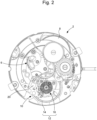
- the watch movement 2 comprises an analog time display 4, a gear train 6, a barrel 8 driving the analog display via the gear train, and an electromechanical oscillator 10 formed by a resonator 12, comprising a balance wheel 14 and a piezoelectric balance spring 16, and a mechanical escapement 18A coupling the balance wheel to the gear train.
- the watch movement is provided with an oscillating weight 24 (not shown in Figures 1 And 2 , but at the Figure 3 ) used to wind the barrel.
- the balance is pivoted in a balance bridge 26, this bridge carrying an index 28 used to adjust the oscillation frequency of the resonator 12, as is usual in mechanical type watch movements.
- the piezoelectric spiral is formed at least partially from a piezoelectric material and comprises at least two electrodes, at least one electrode of which is connected to an electronic control circuit 20.
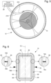
- Figure 5 the resonator 12 and the electronic control circuit 20 are shown, to which two external electrodes 68 and 69 of the piezoelectric spiral 16 are connected by two electrical connections 21A and 21B.
- a cross-section of the piezoelectric spiral 16 is shown in Figure 6 in a non-limiting manner.
- This spiral comprises a central body 60 made of silicon, a layer of silicon oxide 62 deposited on the surface of the central body so as to thermally compensate the spiral, a first conductive layer 64 deposited on the layer of silicon oxide, and a piezoelectric material deposited in the form of a piezoelectric layer 66 on the first conductive layer 64.
- the piezoelectric layer is made of an aluminum nitride crystal formed by growth of this crystal from the first conductive layer and perpendicular thereto.
- Two external electrodes 68 and 69, formed by a second partial conductive layer on the piezoelectric layer, are arranged respectively on the two lateral sides of the spiral and are connected to two respective terminals 70 and 71 of the electronic control circuit 20.
- the piezoelectric layer 66 comprises a first part 74A and a second part 74B which extend respectively on the two lateral sides of the central body 60 and which have, by virtue of their growth from the first conductive layer 64, respective crystallographic structures which are symmetrical relative to a median plane 76 parallel to these two lateral sides.
- the piezoelectric layer 66 has two respective piezoelectric axes 78A and 78B perpendicular to this piezoelectric layer and in opposite directions.
- a certain voltage can be applied between the two electrodes 68 and 69 to actively constrain the hairspring during excitation of the resonator 12 and during a power supply to maintain an oscillation of this resonator.
- the internal electrode, formed of the first conductive layer 64 does not need a specific electrical connection with the electronic control circuit 20 or to the ground of the watch movement, although this is not excluded.
- the piezoelectric material 66 and the two electrodes 68 and 69 are arranged so as to allow the application, controlled by the electronic control circuit 20, of an electrical stress on the piezoelectric balance spring so as to excite the electromechanical oscillator 10, so that the resonator 12 begins to oscillate and obtain an oscillation with a functional amplitude, and then to maintain this functional oscillation.
- the electronic control circuit 20 is connected to an electrical energy source 30 making it possible to apply an electrical supply voltage, between the external electrodes 68 and 69, the value of which is managed by this electronic control circuit.
- the electronic control circuit 20 is arranged to be able to control the application, at least at times, of an electrical supply voltage to at least one of the two external electrodes 68 and 69, so as to electrically excite the electromechanical oscillator 10 to obtain an oscillation of the resonator with a functional amplitude, called functional oscillation, and then to maintain this functional oscillation.
- it is provided to provide driving pulses to the electromechanical oscillator 10, that is to say energy pulses, which make it possible to maintain a functional oscillation of the resonator 12.
- the frequency of these driving pulses depends in particular on their duration and their electrical voltage.
- such driving pulses can be sized so that they intervene once during each alternation or once per period of the resonator oscillation.
- the mechanical escapement 18 is configured so as to be an escapement that counters the alternations of the functional oscillation, in order to be able to regulate the running of the watch movement, without the resonator being able to receive from the barrel via this escapement sufficient mechanical energy to maintain the functional oscillation.
- an oscillation to be functional it must at least have sufficient amplitude to allow the anchor of the mechanical escapement to make back-and-forth movements (alternating movement) between two rest positions in which the balance wheel forming the resonator is released, i.e. not mechanically coupled to the anchor.
- an escapement 18A which forms the output device of the electromechanical oscillator 10 (note that the counter escapement can be considered as part of the oscillator or as being associated with it).
- the escapement 18A is a Swiss lever type escapement whose lever 34 is modified so that its two pallets 35 and 36 each have, at their free end intended to momentarily stop an escape wheel 32, an end surface 37A, respectively 37B whose point of 'contact' with a geometric circle 39 circumscribed to the escape wheel, when the pallet considered is in a corresponding angular position (that is to say in an angular position in which this pallet 'touches' the circumscribed geometric circle 39 without penetrating it), is located at the junction between this end surface 37A, 37B and a lateral surface 38A, respectively 38B of said pallet considered which forms a stop for the teeth 33 of the escape wheel.
- the escapement is configured so that, in normal operation, no tooth 33 slides along the two end surfaces 37A, 37B of the two respective pallets and thus no mechanical impulse (no momentary mechanical force torque) is supplied to the anchor via these two end surfaces, as is the case in a conventional Swiss anchor escapement.
- said junction between the end surface and the lateral surface of each pallet
- said junction can slide successively, at every two steps taken by the escape wheel, on the end of each tooth of this escape wheel and thus the escape wheel can supply at each step a small quantity of mechanical energy to the anchor, which is insufficient to be able to maintain a functional oscillation of the resonator 12.
- this last variant is not implemented in the variant shown in Figure 4 , because the circumscribed geometric circle 39 is defined by the tips of the teeth 33 which come to bear against the lateral surfaces 38A and 38B of the pallets.
- the barrel 8 does not have to power this oscillator so that the mechanical power that the barrel must provide is much less than in a conventional mechanical movement in which the oscillator generally consumes a large part of the energy, in particular when the display is limited to a time display with two or three hands, possibly with the analogue display of the date.
- the minimum mechanical torque necessary to drive the gear train and the analogue display is less than in a conventional mechanical movement where the barrel must be able to exert a torque on the anchor so as to maintain the oscillation of the mechanical resonator.
- Figure 8 is graphically represented the torque as a function of time for a conventional movement (curve 50) and for a watch movement according to the first embodiment of the invention (curve 52) in which the transmission ratio between the barrel and an hour wheel of the analog display has been increased, for the same barrel, relative to a corresponding mechanical movement (i.e. with a conventional Swiss anchor escapement and a usual sprung balance).
- the amount of energy in the barrel remains the same, but the power reserve is increased because the minimum torque C1 min for the conventional mechanical movement is much higher than the minimum torque C2 min for the watch movement 2 according to the invention.
- the transmission ratio between the barrel and the hour wheel of the analog display 4 is substantially equal to or greater than 6/5 (120%). In a preferred variant, this transmission ratio is substantially equal to or greater than 9/5 (180%).
- FIG. 7 shows a preferred embodiment of the electronic control circuit 20 which is arranged to be able to control the application of an electrical supply voltage to at least one terminal/electrode of the piezoelectric balance spring so as to maintain the amplitude of the functional oscillation of the resonator 12/oscillator 14 substantially constant, regardless in particular of the spatial orientation of the watch movement according to the invention, in particular of its resonator 12.
- the electronic control circuit comprises a peak voltage detector 46, arranged to be able to substantially detect the amplitude of the voltage induced in the piezoelectric balance spring 16 when the resonator 12 oscillates, and a regulation circuit 20A which receives from the peak voltage detector a signal S A relating to the amplitude of the induced voltage and which is arranged to manage a supply voltage V A , supplied to the piezoelectric balance spring through a phase-locked loop 20B, as a function of a setpoint value Sc for the signal S A supplied by the detector peak voltage, so as to obtain an oscillation of the resonator with a substantially constant amplitude.
- the setpoint value Sc corresponds to a setpoint amplitude provided for the oscillation of the resonator 12.
- the regulation circuit 20A comprises processing parts P, I, D arranged in parallel and well known to those skilled in the art, which process a difference between the setpoint value Sc and the value of the amplitude signal S A by a proportional response, respectively as a function of an integration and a derivation of this difference over time.
- the regulation circuit also receives a reference voltage V R which is adjusted according to the regulation carried out by the circuit 20A.
- a buffer element 44 high input impedance transistor
- the phase-locked loop 20B slaves the phase of the periodic power supply signal to the phase of the induced voltage signal, supplied in particular to terminal 71, so that the power supply voltage constrains the piezoelectric balance spring in the direction of its movement, which is either in contraction or in extension depending on the current alternation.
- the circuit 20B detects the zero crossings of the induced voltage, in particular at terminal 71.
- the polarity of the power supply voltage is selected so as to constrain the piezoelectric balance spring in the direction of its movement, which is alternately in extension and in contraction during the alternations of the oscillation of the resonator.
- a quartz oscillator is incorporated in the electronic control circuit 20.
- This quartz oscillator can be used for various needs.
- the management of the supply voltage V A can comprise a modulation of the driving pulses with a variable duty cycle as a function of the amplitude signal S A and the setpoint value Sc, in particular their difference.
- the driving pulses are triggered with a setpoint frequency Fc for the oscillator 10 / the resonator 12 which is determined very precisely by the quartz oscillator.
- the frequency Fs of the supply signal is not too far from the resonant frequency of the resonator, namely its natural frequency F N , twice this natural frequency or possibly an integer division of this double frequency, such a power supply of the piezoelectric spiral can impose the set frequency on the resonator 12 maintained by said driving pulses while ensuring sufficient amplitude for functional oscillation, even for an electrical power supply managed in such a way as to optimize its consumption, so that the electromechanical oscillator 10 will be able to oscillate at the set frequency, with the precision of quartz, and a functional amplitude whatever the spatial orientation of the watch movement.
- the advantageous variant described above can be easily implemented to obtain a gain in precision for the running of the watch movement, and therefore of the watch which incorporates it, with almost no increase in the electrical consumption linked to the maintenance of a functional oscillation. It should be noted that, in this advantageous variant, the power supply circuit does not need to include a phase-locked loop; which simplifies its design.
- N N Tc / 2
- D T N Tc / 2
- N being greater than zero.
- the number N which can be variable, is provided sufficiently small to ensure the maintenance of a functional oscillation and it is selected in a range of values allowing to impose the set frequency Fc on the electromechanical oscillator, this range of values being a function of the range of natural frequencies possible for this oscillator, which is kept sufficiently close to the set frequency thanks to the first regulation mentioned above.
- the second regulation by a periodic supply signal determined by the quartz oscillator, in particular by driving pulses at the set frequency Fc, is guaranteed with a relatively large functional amplitude, provided that the number N is not too high. This gives a precision of the rate of the watch movement which is equal to that of the quartz oscillator for any spatial orientation of the watch movement.
- the supply circuit does not need to include a phase-locked loop.
- a quartz oscillator is incorporated into the electronic control circuit of the power supply device.
- a quartz oscillator is added to the electronic control circuit to allow regulation of the oscillation of the sprung balance so that its average frequency is regulated and determined by a reference frequency generated by the quartz oscillator.
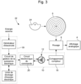
- FIG. 3 schematically represents a watch 22 according to the invention comprising a watch movement according to the invention.
- the parts of the watch movement already described will not be described again here in detail.
- the watch 22 comprises an electrical energy source 30 which is formed by an electricity generator arranged to produce electricity so as to enable power supply to the electronic control circuit and the piezoelectric balance spring.
- the electricity generator is connected to a storage unit, in particular a rechargeable battery or a super-capacitor, via a circuit for managing the electrical power supplied to the electronic control circuit 20 and to the electromechanical oscillator 10.
- the voltage necessary to power the piezoelectric balance spring is located in a voltage range between 10 V and 40 V.
- the electrical power management circuit is arranged to be able to increase the voltage accumulated in the storage unit or supplied directly by the electricity generator.
- a voltage booster for example a charge pump.
- thermopile is provided which receives as energy external to the watch thermal energy coming from the user's arm. The thermopile is thus arranged so as to be able to convert heat from the body of a user in electricity.
- the watch according to the invention does not include an electric generator which makes it autonomous, but it includes a battery in the form of a standard cell.
Landscapes
- Physics & Mathematics (AREA)
- General Physics & Mathematics (AREA)
- Engineering & Computer Science (AREA)
- Manufacturing & Machinery (AREA)
- Metallurgy (AREA)
- Electric Clocks (AREA)
- Electromechanical Clocks (AREA)
- Oscillators With Electromechanical Resonators (AREA)
Claims (11)
- Uhrwerk (2), das eine analoge Zeitanzeige (4), ein Räderwerk (6), ein Federhaus (8), das die analoge Anzeige über das Räderwerk antreibt, und einen Oszillator (10), der aus einem Resonator (12), der eine Unruh (14) und eine piezoelektrische Spirale (16) umfasst, und aus einer mechanischen Hemmung (18; 18A) gebildet wird, welche die Unruh mit dem Räderwerk koppelt, umfasst, wobei die piezoelektrische Spirale zumindest teilweise aus einem piezoelektrischen Werkstoff (66) gebildet ist und mindestens zwei Elektroden (68, 69) umfasst, von denen mindestens eine Elektrode mit einer elektronischen Steuerschaltung (20) verbunden ist, wobei der piezoelektrische Werkstoff und die mindestens eine Elektrode angeordnet sind, um das von der elektronischen Steuerschaltung verwaltete Anlegen einer elektrischen Spannung an die piezoelektrische Spirale zu ermöglichen; wobei die elektronische Steuerschaltung angeordnet ist, um mit einer elektrischen Energiequelle (30) verbunden werden zu können, und um das zumindest zeitweise Anlegen einer elektrischen Versorgungsspannung an die mindestens eine Elektrode steuern zu können, um den Oszillator anzuregen, um eine funktionelle Schwingung des Resonators zu erhalten, und um diese funktionelle Schwingung danach aufrechtzuerhalten; und wobei die mechanische Hemmung (18; 18A) konfiguriert ist, um eine Zählerhemmung für die Halbschwingungen der funktionellen Schwingung zu sein, um so den Rhythmus des Ganges des Uhrwerks zu bestimmen, ohne dass der Resonator vom Federhaus über diese mechanische Hemmung eine mechanische Energie erhalten kann, die zur Aufrechterhaltung der funktionellen Schwingung ausreicht.
- Uhrwerk nach Anspruch 1, dadurch gekennzeichnet, dass die elektronische Steuerschaltung (20) angeordnet ist, um das Anlegen einer elektrischen Versorgungsspannung zu steuern, um die Amplitude der funktionellen Schwingung im Wesentlichen konstant zu halten.
- Uhrwerk nach Anspruch 2, dadurch gekennzeichnet, dass die elektronische Steuerschaltung (20) einen Spitzenspannungsdetektor (46) umfasst, der angeordnet ist, um die Amplitude einer in der piezoelektrischen Spirale (16) induzierten Spannung im Wesentlichen detektieren zu können, wenn der Resonator (12) oszilliert, und eine Regelschaltung (20A), die von dem Spitzenspannungsdetektor ein Signal (SA) in Bezug auf die Amplitude der induzierten Spannung empfängt, und die angeordnet ist, um eine Versorgungsspannung (VA) in Abhängigkeit von einem Sollwert (Sc) für das Signal (SA), das von dem Spitzenspannungsdetektor geliefert wird, verwalten zu können, um eine Schwingung des Resonators mit einer im Wesentlichen konstanten Amplitude zu erhalten.
- Uhrwerk nach einem der vorstehenden Ansprüche, dadurch gekennzeichnet, dass das Übersetzungsverhältnis zwischen dem Federhaus und einem Stundenrad der analogen Anzeige gleich oder größer als 6/5 (120 %) ist.
- Uhrwerk nach einem der vorstehenden Ansprüche, dadurch gekennzeichnet, dass das Übersetzungsverhältnis zwischen dem Federhaus und einem Stundenrad der analogen Anzeige gleich oder größer als 9/5 (180 %) ist.
- Uhrwerk nach einem der vorstehenden Ansprüche, dadurch gekennzeichnet, dass die mechanische Hemmung konfiguriert ist, um eine Hemmung nur zum Zählen der Halbschwingungen der funktionellen Schwingung zu sein; und dadurch, dass die elektronische Steuerschaltung angeordnet ist, um allein diese funktionelle Schwingung aufrechterhalten zu können.
- Uhrwerk nach Anspruch 6, dadurch gekennzeichnet, dass die Hemmung (18A) eine Hemmung vom Typ Schweizer Anker ist, die modifiziert ist, sodass die beiden Paletten (34, 35) des Ankers (34) jeweils an ihrem freien Ende, das dazu vorgesehen ist, ein Hemmungsrad (32) vorübergehend zu stoppen, eine Endoberfläche (37A, 37B) aufweisen, deren Berührungspunkt mit einem Kreis (39), der das Hemmungsrad umschreibt, wenn sich die betreffende Palette in einer entsprechenden Winkelposition befindet, an der Verbindung zwischen dieser Endoberfläche und einer Seitenoberfläche (38A, 38B) der betreffenden Palette liegt, die einen Anschlag für die Zähne (33) des Hemmungsrades bildet.
- Uhrwerk nach einem der vorstehenden Ansprüche, dadurch gekennzeichnet, dass es mit einer Schwungmasse (24) zum automatischen Aufziehen des Federhauses (8) versehen ist.
- Uhr (22), die ein Uhrwerk (2) nach einem der vorstehenden Ansprüche umfasst, dadurch gekennzeichnet, dass die Energiequelle in dieser Uhr verbaut ist und einen Stromgenerator umfasst, der angeordnet ist, um Strom zu erzeugen, um eine Versorgung der elektronischen Steuerschaltung (20) und der piezoelektrischen Spiralfeder (16) zu ermöglichen.
- Uhr nach Anspruch 9, dadurch gekennzeichnet, dass der Stromgenerator einen Lichtsensor umfasst.
- Uhr nach Anspruch 9, dadurch gekennzeichnet, dass der Stromgenerator eine Thermosäule umfasst, die angeordnet ist, um die Wärme eines Körpers eines Benutzers in Strom umwandeln zu können.
Applications Claiming Priority (1)
| Application Number | Priority Date | Filing Date | Title |
|---|---|---|---|
| EP21177468 | 2021-06-02 |
Publications (2)
| Publication Number | Publication Date |
|---|---|
| EP4099100A1 EP4099100A1 (de) | 2022-12-07 |
| EP4099100B1 true EP4099100B1 (de) | 2025-03-12 |
Family
ID=76250246
Family Applications (1)
| Application Number | Title | Priority Date | Filing Date |
|---|---|---|---|
| EP22171187.2A Active EP4099100B1 (de) | 2021-06-02 | 2022-05-02 | Uhrwerk, das mit einem oszillator ausgestattet ist, der eine piezoelektrische spirale enthält |
Country Status (4)
| Country | Link |
|---|---|
| US (1) | US12282298B2 (de) |
| EP (1) | EP4099100B1 (de) |
| JP (1) | JP7297126B2 (de) |
| CN (1) | CN115437231B (de) |
Families Citing this family (1)
| Publication number | Priority date | Publication date | Assignee | Title |
|---|---|---|---|---|
| EP4130890B1 (de) | 2021-08-04 | 2024-03-27 | The Swatch Group Research and Development Ltd | Uhrwerk mit oszillator, der eine piezoelektrische spiralfeder enthält |
Family Cites Families (20)
| Publication number | Priority date | Publication date | Assignee | Title |
|---|---|---|---|---|
| JPS6448565A (en) | 1987-08-19 | 1989-02-23 | Ricoh Kk | Picture processor |
| WO2001048565A1 (en) | 1999-12-24 | 2001-07-05 | Seiko Instruments Inc. | Mechanical timepiece having train wheel operation controller |
| JP2001048565A (ja) * | 1999-08-09 | 2001-02-20 | Sumitomo Electric Ind Ltd | 光ファイバ母材の延伸方法 |
| JP3767388B2 (ja) * | 2001-01-30 | 2006-04-19 | セイコーエプソン株式会社 | 圧電調速機およびこの圧電調速機を用いた電子機器 |
| US7922385B2 (en) * | 2007-03-01 | 2011-04-12 | Seiko Epson Corporation | Piezoelectric drive device and electronic device |
| EP2561409B1 (de) * | 2010-04-21 | 2019-08-28 | Team Smartfish GmbH | Regelorgan für ein uhrwerk, und entsprechendes verfahren |
| CH705679B1 (fr) * | 2011-10-28 | 2017-01-31 | Swatch Group Res & Dev Ltd | Circuit d'autorégulation de la fréquence d'oscillation d'un système mécanique oscillant, et dispositif le comprenant. |
| EP2613205A3 (de) | 2012-01-09 | 2016-07-13 | Lvmh Swiss Manufactures SA | Regulierorgan für Armbanduhr oder Chronografen |
| JP6254084B2 (ja) | 2012-07-27 | 2017-12-27 | クラリオン株式会社 | 画像処理装置 |
| EP2908185B1 (de) | 2014-02-17 | 2017-09-13 | The Swatch Group Research and Development Ltd. | Wartungs- und Regulierungsgerät eines Uhrenresonators |
| EP3339982B1 (de) | 2016-12-23 | 2021-08-25 | The Swatch Group Research and Development Ltd | Regulierung durch mechanisches bremsen eines mechanischen oszillators einer uhr |
| CH713332A2 (fr) | 2016-12-23 | 2018-06-29 | Swatch Group Res & Dev Ltd | Ensemble horloger comprenant un oscillateur mécanique associé à un dispositif de régulation. |
| EP3457224B1 (de) * | 2017-09-14 | 2020-10-28 | The Swatch Group Research and Development Ltd | Piezoelektrisches element für einen schaltkreis zur frequenzselbstregulierung, schwingendes mechanisches system und dieses umfassende vorrichtung, und herstellungsverfahren eines solchen piezoelektrischen elements |
| EP3457223A1 (de) * | 2017-09-14 | 2019-03-20 | The Swatch Group Research and Development Ltd | Piezoelektrisches element für einen schaltkreis zur frequenzselbstregulierung, schwingendes mechanisches system und dieses umfassende vorrichtung |
| EP3502796B1 (de) | 2017-12-20 | 2020-05-20 | The Swatch Group Research and Development Ltd | Uhrwerksanordnung, die einen mechanischen oszillator umfasst, der mit einer einstellvorrichtung verbunden ist |
| EP3540528B1 (de) | 2018-03-16 | 2020-08-05 | The Swatch Group Research and Development Ltd | Uhr, die ein mechanisches uhrwerk umfasst, dessen ganggenauigkeit durch eine elektronische vorrichtung reguliert wird |
| CH714839A1 (fr) * | 2018-03-27 | 2019-09-30 | Csem Centre Suisse Delectronique Et De Microtechnique Sa | Garde-temps comportant un oscillateur mécanique. |
| EP3579058B1 (de) | 2018-06-07 | 2021-09-15 | Montres Breguet S.A. | Uhr, die ein tourbillon umfasst |
| EP3629104B1 (de) * | 2018-09-27 | 2021-05-12 | The Swatch Group Research and Development Ltd | Mechanische uhr umfassend eine elektronische vorrichtung zur regulierung der ganggenauigkeit der uhr |
| EP3629103B1 (de) | 2018-09-28 | 2021-05-12 | The Swatch Group Research and Development Ltd | Uhr, die ein mechanisches uhrwerk umfasst, dessen ganggenauigkeit durch eine elektronische vorrichtung reguliert wird |
-
2022
- 2022-05-02 EP EP22171187.2A patent/EP4099100B1/de active Active
- 2022-05-10 US US17/662,691 patent/US12282298B2/en active Active
- 2022-05-25 JP JP2022084972A patent/JP7297126B2/ja active Active
- 2022-06-01 CN CN202210629526.0A patent/CN115437231B/zh active Active
Also Published As
| Publication number | Publication date |
|---|---|
| US20220390901A1 (en) | 2022-12-08 |
| JP2022185575A (ja) | 2022-12-14 |
| CN115437231B (zh) | 2024-09-10 |
| EP4099100A1 (de) | 2022-12-07 |
| JP7297126B2 (ja) | 2023-06-23 |
| CN115437231A (zh) | 2022-12-06 |
| US12282298B2 (en) | 2025-04-22 |
Similar Documents
| Publication | Publication Date | Title |
|---|---|---|
| EP3629103B1 (de) | Uhr, die ein mechanisches uhrwerk umfasst, dessen ganggenauigkeit durch eine elektronische vorrichtung reguliert wird | |
| EP3457223A1 (de) | Piezoelektrisches element für einen schaltkreis zur frequenzselbstregulierung, schwingendes mechanisches system und dieses umfassende vorrichtung | |
| EP3629104B1 (de) | Mechanische uhr umfassend eine elektronische vorrichtung zur regulierung der ganggenauigkeit der uhr | |
| EP3842876A1 (de) | Uhr, die mit einem mechanischen uhrwerk und einer vorrichtung zur korrektur der angezeigten stunde ausgestattet ist | |
| CH705679A2 (fr) | Circuit d'autorégulation de la fréquence d'oscillation d'un système mécanique oscillant, et dispositif le comprenant. | |
| EP3457224B1 (de) | Piezoelektrisches element für einen schaltkreis zur frequenzselbstregulierung, schwingendes mechanisches system und dieses umfassende vorrichtung, und herstellungsverfahren eines solchen piezoelektrischen elements | |
| EP3502798B1 (de) | Uhrwerksanordnung, die einen mechanischen oszillator umfasst, der mit einer einstellvorrichtung verbunden ist | |
| EP4099100B1 (de) | Uhrwerk, das mit einem oszillator ausgestattet ist, der eine piezoelektrische spirale enthält | |
| EP3540528B1 (de) | Uhr, die ein mechanisches uhrwerk umfasst, dessen ganggenauigkeit durch eine elektronische vorrichtung reguliert wird | |
| EP4130890B1 (de) | Uhrwerk mit oszillator, der eine piezoelektrische spiralfeder enthält | |
| CH718689A2 (fr) | Mouvement horloger muni d'un oscillateur comprenant un spiral piézoélectrique. | |
| EP2590035B1 (de) | Schaltkreis zur Selbstregulierung der Schwingungsfrequenz eines schwingenden mechanischen Systems, und diesen umfassende Vorrichtung | |
| CH718897A2 (fr) | Mouvement horloger muni d'un oscillateur comprenant un spiral piézoélectrique. | |
| CH714144A2 (fr) | Elément piézoélectrique pour un circuit d'autorégulation de fréquence, système mécanique oscillant et dispositif le comprenant, et procédé de fabrication de l'élément piézoélectrique. | |
| EP4078298B1 (de) | Uhr, die mit einem mechanischen uhrwerk und einer korrekturvorrichtung für die stundenanzeige ausgestattet ist | |
| HK40078718B (zh) | 设有包括压电式游丝的振荡器的钟表机芯 | |
| CH714794A2 (fr) | Pièce d'horlogerie comprenant un mouvement mécanique dont la marche est régulée par un dispositif électronique. | |
| HK40078718A (en) | Horological movement provided with an oscillator comprising a piezoelectric spring | |
| CH694621A5 (fr) | Procédé de régulation et module électronique de régulation pour mouvement d'horlogerie à remontage mécanique. | |
| EP4194960B1 (de) | Piezoelektrische spiralfeder und verfahren zur herstellung dieser spiralfeder | |
| CH714143A2 (fr) | Elément piézoélectrique pour un circuit d'autorégulation de fréquence, et système mécanique oscillant et dispositif le comprenant. | |
| CH715392A2 (fr) | Pièce d'horlogerie comprenant un mouvement mécanique dont la marche est régulée par un dispositif électronique. | |
| EP2343747A1 (de) | Vorrichtung zur Erzeugung von elektrischer Energie für tragbares Gerät, insbesondere für Uhr | |
| CH719240A2 (fr) | Ressort spiral piézoélectrique, et procédé de fabrication du ressort spiral. | |
| EP3140698A2 (de) | Stimmgabel für mechanischen oszillator für uhrwerk |
Legal Events
| Date | Code | Title | Description |
|---|---|---|---|
| PUAI | Public reference made under article 153(3) epc to a published international application that has entered the european phase |
Free format text: ORIGINAL CODE: 0009012 |
|
| STAA | Information on the status of an ep patent application or granted ep patent |
Free format text: STATUS: THE APPLICATION HAS BEEN PUBLISHED |
|
| AK | Designated contracting states |
Kind code of ref document: A1 Designated state(s): AL AT BE BG CH CY CZ DE DK EE ES FI FR GB GR HR HU IE IS IT LI LT LU LV MC MK MT NL NO PL PT RO RS SE SI SK SM TR |
|
| STAA | Information on the status of an ep patent application or granted ep patent |
Free format text: STATUS: REQUEST FOR EXAMINATION WAS MADE |
|
| 17P | Request for examination filed |
Effective date: 20230607 |
|
| RBV | Designated contracting states (corrected) |
Designated state(s): AL AT BE BG CH CY CZ DE DK EE ES FI FR GB GR HR HU IE IS IT LI LT LU LV MC MK MT NL NO PL PT RO RS SE SI SK SM TR |
|
| P01 | Opt-out of the competence of the unified patent court (upc) registered |
Effective date: 20230615 |
|
| GRAP | Despatch of communication of intention to grant a patent |
Free format text: ORIGINAL CODE: EPIDOSNIGR1 |
|
| STAA | Information on the status of an ep patent application or granted ep patent |
Free format text: STATUS: GRANT OF PATENT IS INTENDED |
|
| INTG | Intention to grant announced |
Effective date: 20241104 |
|
| GRAS | Grant fee paid |
Free format text: ORIGINAL CODE: EPIDOSNIGR3 |
|
| GRAA | (expected) grant |
Free format text: ORIGINAL CODE: 0009210 |
|
| STAA | Information on the status of an ep patent application or granted ep patent |
Free format text: STATUS: THE PATENT HAS BEEN GRANTED |
|
| AK | Designated contracting states |
Kind code of ref document: B1 Designated state(s): AL AT BE BG CH CY CZ DE DK EE ES FI FR GB GR HR HU IE IS IT LI LT LU LV MC MK MT NL NO PL PT RO RS SE SI SK SM TR |
|
| REG | Reference to a national code |
Ref country code: GB Ref legal event code: FG4D Free format text: NOT ENGLISH |
|
| REG | Reference to a national code |
Ref country code: CH Ref legal event code: EP |
|
| REG | Reference to a national code |
Ref country code: DE Ref legal event code: R096 Ref document number: 602022011600 Country of ref document: DE |
|
| REG | Reference to a national code |
Ref country code: IE Ref legal event code: FG4D Free format text: LANGUAGE OF EP DOCUMENT: FRENCH |
|
| PG25 | Lapsed in a contracting state [announced via postgrant information from national office to epo] |
Ref country code: RS Free format text: LAPSE BECAUSE OF FAILURE TO SUBMIT A TRANSLATION OF THE DESCRIPTION OR TO PAY THE FEE WITHIN THE PRESCRIBED TIME-LIMIT Effective date: 20250612 |
|
| PG25 | Lapsed in a contracting state [announced via postgrant information from national office to epo] |
Ref country code: FI Free format text: LAPSE BECAUSE OF FAILURE TO SUBMIT A TRANSLATION OF THE DESCRIPTION OR TO PAY THE FEE WITHIN THE PRESCRIBED TIME-LIMIT Effective date: 20250312 |
|
| PGFP | Annual fee paid to national office [announced via postgrant information from national office to epo] |
Ref country code: DE Payment date: 20250423 Year of fee payment: 4 |
|
| PG25 | Lapsed in a contracting state [announced via postgrant information from national office to epo] |
Ref country code: ES Free format text: LAPSE BECAUSE OF FAILURE TO SUBMIT A TRANSLATION OF THE DESCRIPTION OR TO PAY THE FEE WITHIN THE PRESCRIBED TIME-LIMIT Effective date: 20250312 |
|
| REG | Reference to a national code |
Ref country code: LT Ref legal event code: MG9D |
|
| PG25 | Lapsed in a contracting state [announced via postgrant information from national office to epo] |
Ref country code: NO Free format text: LAPSE BECAUSE OF FAILURE TO SUBMIT A TRANSLATION OF THE DESCRIPTION OR TO PAY THE FEE WITHIN THE PRESCRIBED TIME-LIMIT Effective date: 20250612 |
|
| PG25 | Lapsed in a contracting state [announced via postgrant information from national office to epo] |
Ref country code: HR Free format text: LAPSE BECAUSE OF FAILURE TO SUBMIT A TRANSLATION OF THE DESCRIPTION OR TO PAY THE FEE WITHIN THE PRESCRIBED TIME-LIMIT Effective date: 20250312 |
|
| REG | Reference to a national code |
Ref country code: NL Ref legal event code: MP Effective date: 20250312 |
|
| PG25 | Lapsed in a contracting state [announced via postgrant information from national office to epo] |
Ref country code: LV Free format text: LAPSE BECAUSE OF FAILURE TO SUBMIT A TRANSLATION OF THE DESCRIPTION OR TO PAY THE FEE WITHIN THE PRESCRIBED TIME-LIMIT Effective date: 20250312 |
|
| PGFP | Annual fee paid to national office [announced via postgrant information from national office to epo] |
Ref country code: FR Payment date: 20250423 Year of fee payment: 4 |
|
| PG25 | Lapsed in a contracting state [announced via postgrant information from national office to epo] |
Ref country code: GR Free format text: LAPSE BECAUSE OF FAILURE TO SUBMIT A TRANSLATION OF THE DESCRIPTION OR TO PAY THE FEE WITHIN THE PRESCRIBED TIME-LIMIT Effective date: 20250613 Ref country code: BG Free format text: LAPSE BECAUSE OF FAILURE TO SUBMIT A TRANSLATION OF THE DESCRIPTION OR TO PAY THE FEE WITHIN THE PRESCRIBED TIME-LIMIT Effective date: 20250312 |
|
| PGFP | Annual fee paid to national office [announced via postgrant information from national office to epo] |
Ref country code: CH Payment date: 20250601 Year of fee payment: 4 |
|
| REG | Reference to a national code |
Ref country code: AT Ref legal event code: MK05 Ref document number: 1775495 Country of ref document: AT Kind code of ref document: T Effective date: 20250312 |
|
| PG25 | Lapsed in a contracting state [announced via postgrant information from national office to epo] |
Ref country code: NL Free format text: LAPSE BECAUSE OF FAILURE TO SUBMIT A TRANSLATION OF THE DESCRIPTION OR TO PAY THE FEE WITHIN THE PRESCRIBED TIME-LIMIT Effective date: 20250312 |
|
| PG25 | Lapsed in a contracting state [announced via postgrant information from national office to epo] |
Ref country code: SE Free format text: LAPSE BECAUSE OF FAILURE TO SUBMIT A TRANSLATION OF THE DESCRIPTION OR TO PAY THE FEE WITHIN THE PRESCRIBED TIME-LIMIT Effective date: 20250312 |
|
| PG25 | Lapsed in a contracting state [announced via postgrant information from national office to epo] |
Ref country code: SM Free format text: LAPSE BECAUSE OF FAILURE TO SUBMIT A TRANSLATION OF THE DESCRIPTION OR TO PAY THE FEE WITHIN THE PRESCRIBED TIME-LIMIT Effective date: 20250312 |
|
| PG25 | Lapsed in a contracting state [announced via postgrant information from national office to epo] |
Ref country code: PT Free format text: LAPSE BECAUSE OF FAILURE TO SUBMIT A TRANSLATION OF THE DESCRIPTION OR TO PAY THE FEE WITHIN THE PRESCRIBED TIME-LIMIT Effective date: 20250714 |
|
| PG25 | Lapsed in a contracting state [announced via postgrant information from national office to epo] |
Ref country code: IT Free format text: LAPSE BECAUSE OF FAILURE TO SUBMIT A TRANSLATION OF THE DESCRIPTION OR TO PAY THE FEE WITHIN THE PRESCRIBED TIME-LIMIT Effective date: 20250312 Ref country code: PL Free format text: LAPSE BECAUSE OF FAILURE TO SUBMIT A TRANSLATION OF THE DESCRIPTION OR TO PAY THE FEE WITHIN THE PRESCRIBED TIME-LIMIT Effective date: 20250312 |
|
| PG25 | Lapsed in a contracting state [announced via postgrant information from national office to epo] |
Ref country code: AT Free format text: LAPSE BECAUSE OF FAILURE TO SUBMIT A TRANSLATION OF THE DESCRIPTION OR TO PAY THE FEE WITHIN THE PRESCRIBED TIME-LIMIT Effective date: 20250312 |
|
| PG25 | Lapsed in a contracting state [announced via postgrant information from national office to epo] |
Ref country code: CZ Free format text: LAPSE BECAUSE OF FAILURE TO SUBMIT A TRANSLATION OF THE DESCRIPTION OR TO PAY THE FEE WITHIN THE PRESCRIBED TIME-LIMIT Effective date: 20250312 Ref country code: EE Free format text: LAPSE BECAUSE OF FAILURE TO SUBMIT A TRANSLATION OF THE DESCRIPTION OR TO PAY THE FEE WITHIN THE PRESCRIBED TIME-LIMIT Effective date: 20250312 |
|
| PG25 | Lapsed in a contracting state [announced via postgrant information from national office to epo] |
Ref country code: RO Free format text: LAPSE BECAUSE OF FAILURE TO SUBMIT A TRANSLATION OF THE DESCRIPTION OR TO PAY THE FEE WITHIN THE PRESCRIBED TIME-LIMIT Effective date: 20250312 |
|
| PG25 | Lapsed in a contracting state [announced via postgrant information from national office to epo] |
Ref country code: SK Free format text: LAPSE BECAUSE OF FAILURE TO SUBMIT A TRANSLATION OF THE DESCRIPTION OR TO PAY THE FEE WITHIN THE PRESCRIBED TIME-LIMIT Effective date: 20250312 |
|
| PG25 | Lapsed in a contracting state [announced via postgrant information from national office to epo] |
Ref country code: IS Free format text: LAPSE BECAUSE OF FAILURE TO SUBMIT A TRANSLATION OF THE DESCRIPTION OR TO PAY THE FEE WITHIN THE PRESCRIBED TIME-LIMIT Effective date: 20250712 |
|
| REG | Reference to a national code |
Ref country code: DE Ref legal event code: R097 Ref document number: 602022011600 Country of ref document: DE |
|
| PG25 | Lapsed in a contracting state [announced via postgrant information from national office to epo] |
Ref country code: DK Free format text: LAPSE BECAUSE OF FAILURE TO SUBMIT A TRANSLATION OF THE DESCRIPTION OR TO PAY THE FEE WITHIN THE PRESCRIBED TIME-LIMIT Effective date: 20250312 |
|
| PG25 | Lapsed in a contracting state [announced via postgrant information from national office to epo] |
Ref country code: LU Free format text: LAPSE BECAUSE OF NON-PAYMENT OF DUE FEES Effective date: 20250502 |
|
| PLBE | No opposition filed within time limit |
Free format text: ORIGINAL CODE: 0009261 |
|
| STAA | Information on the status of an ep patent application or granted ep patent |
Free format text: STATUS: NO OPPOSITION FILED WITHIN TIME LIMIT |
|
| REG | Reference to a national code |
Ref country code: CH Ref legal event code: L10 Free format text: ST27 STATUS EVENT CODE: U-0-0-L10-L00 (AS PROVIDED BY THE NATIONAL OFFICE) Effective date: 20260121 |
|
| REG | Reference to a national code |
Ref country code: BE Ref legal event code: MM Effective date: 20250531 |
|
| PG25 | Lapsed in a contracting state [announced via postgrant information from national office to epo] |
Ref country code: MC Free format text: LAPSE BECAUSE OF FAILURE TO SUBMIT A TRANSLATION OF THE DESCRIPTION OR TO PAY THE FEE WITHIN THE PRESCRIBED TIME-LIMIT Effective date: 20250312 |
|
| 26N | No opposition filed |
Effective date: 20251215 |
|
| PG25 | Lapsed in a contracting state [announced via postgrant information from national office to epo] |
Ref country code: IE Free format text: LAPSE BECAUSE OF NON-PAYMENT OF DUE FEES Effective date: 20250502 |
|
| PG25 | Lapsed in a contracting state [announced via postgrant information from national office to epo] |
Ref country code: BE Free format text: LAPSE BECAUSE OF NON-PAYMENT OF DUE FEES Effective date: 20250531 |