EP4098994B1 - Gassammelvorrichtung - Google Patents
Gassammelvorrichtung Download PDFInfo
- Publication number
- EP4098994B1 EP4098994B1 EP21892094.0A EP21892094A EP4098994B1 EP 4098994 B1 EP4098994 B1 EP 4098994B1 EP 21892094 A EP21892094 A EP 21892094A EP 4098994 B1 EP4098994 B1 EP 4098994B1
- Authority
- EP
- European Patent Office
- Prior art keywords
- flow path
- unit
- gas
- constant temperature
- culture flask
- Prior art date
- Legal status (The legal status is an assumption and is not a legal conclusion. Google has not performed a legal analysis and makes no representation as to the accuracy of the status listed.)
- Active
Links
Images

Classifications
-
- G—PHYSICS
- G01—MEASURING; TESTING
- G01N—INVESTIGATING OR ANALYSING MATERIALS BY DETERMINING THEIR CHEMICAL OR PHYSICAL PROPERTIES
- G01N1/00—Sampling; Preparing specimens for investigation
- G01N1/02—Devices for withdrawing samples
- G01N1/22—Devices for withdrawing samples in the gaseous state
- G01N1/2202—Devices for withdrawing samples in the gaseous state involving separation of sample components during sampling
- G01N1/2214—Devices for withdrawing samples in the gaseous state involving separation of sample components during sampling by sorption
-
- G—PHYSICS
- G01—MEASURING; TESTING
- G01N—INVESTIGATING OR ANALYSING MATERIALS BY DETERMINING THEIR CHEMICAL OR PHYSICAL PROPERTIES
- G01N1/00—Sampling; Preparing specimens for investigation
- G01N1/02—Devices for withdrawing samples
- G01N1/22—Devices for withdrawing samples in the gaseous state
- G01N1/2226—Sampling from a closed space, e.g. food package, head space
-
- G—PHYSICS
- G01—MEASURING; TESTING
- G01N—INVESTIGATING OR ANALYSING MATERIALS BY DETERMINING THEIR CHEMICAL OR PHYSICAL PROPERTIES
- G01N1/00—Sampling; Preparing specimens for investigation
- G01N1/02—Devices for withdrawing samples
- G01N1/22—Devices for withdrawing samples in the gaseous state
- G01N1/24—Suction devices
-
- G—PHYSICS
- G01—MEASURING; TESTING
- G01N—INVESTIGATING OR ANALYSING MATERIALS BY DETERMINING THEIR CHEMICAL OR PHYSICAL PROPERTIES
- G01N1/00—Sampling; Preparing specimens for investigation
- G01N1/28—Preparing specimens for investigation including physical details of (bio-)chemical methods covered elsewhere, e.g. G01N33/50, C12Q
- G01N1/40—Concentrating samples
- G01N1/405—Concentrating samples by adsorption or absorption
-
- G—PHYSICS
- G01—MEASURING; TESTING
- G01N—INVESTIGATING OR ANALYSING MATERIALS BY DETERMINING THEIR CHEMICAL OR PHYSICAL PROPERTIES
- G01N33/00—Investigating or analysing materials by specific methods not covered by groups G01N1/00 - G01N31/00
- G01N33/48—Biological material, e.g. blood, urine; Haemocytometers
- G01N33/483—Physical analysis of biological material
- G01N33/497—Physical analysis of biological material of gaseous biological material, e.g. breath
- G01N33/4977—Metabolic gas from microbes, cell cultures or plant tissues
-
- C—CHEMISTRY; METALLURGY
- C12—BIOCHEMISTRY; BEER; SPIRITS; WINE; VINEGAR; MICROBIOLOGY; ENZYMOLOGY; MUTATION OR GENETIC ENGINEERING
- C12M—APPARATUS FOR ENZYMOLOGY OR MICROBIOLOGY; APPARATUS FOR CULTURING MICROORGANISMS FOR PRODUCING BIOMASS, FOR GROWING CELLS OR FOR OBTAINING FERMENTATION OR METABOLIC PRODUCTS, i.e. BIOREACTORS OR FERMENTERS
- C12M21/00—Bioreactors or fermenters specially adapted for specific uses
- C12M21/04—Bioreactors or fermenters specially adapted for specific uses for producing gas, e.g. biogas
-
- C—CHEMISTRY; METALLURGY
- C12—BIOCHEMISTRY; BEER; SPIRITS; WINE; VINEGAR; MICROBIOLOGY; ENZYMOLOGY; MUTATION OR GENETIC ENGINEERING
- C12M—APPARATUS FOR ENZYMOLOGY OR MICROBIOLOGY; APPARATUS FOR CULTURING MICROORGANISMS FOR PRODUCING BIOMASS, FOR GROWING CELLS OR FOR OBTAINING FERMENTATION OR METABOLIC PRODUCTS, i.e. BIOREACTORS OR FERMENTERS
- C12M23/00—Constructional details, e.g. recesses, hinges
- C12M23/36—Means for collection or storage of gas; Gas holders
-
- G—PHYSICS
- G01—MEASURING; TESTING
- G01N—INVESTIGATING OR ANALYSING MATERIALS BY DETERMINING THEIR CHEMICAL OR PHYSICAL PROPERTIES
- G01N1/00—Sampling; Preparing specimens for investigation
- G01N1/02—Devices for withdrawing samples
- G01N1/22—Devices for withdrawing samples in the gaseous state
- G01N2001/2244—Exhaled gas, e.g. alcohol detecting
-
- G—PHYSICS
- G01—MEASURING; TESTING
- G01N—INVESTIGATING OR ANALYSING MATERIALS BY DETERMINING THEIR CHEMICAL OR PHYSICAL PROPERTIES
- G01N1/00—Sampling; Preparing specimens for investigation
- G01N1/02—Devices for withdrawing samples
- G01N1/22—Devices for withdrawing samples in the gaseous state
- G01N1/24—Suction devices
- G01N2001/242—Injectors or ejectors
-
- G—PHYSICS
- G01—MEASURING; TESTING
- G01N—INVESTIGATING OR ANALYSING MATERIALS BY DETERMINING THEIR CHEMICAL OR PHYSICAL PROPERTIES
- G01N1/00—Sampling; Preparing specimens for investigation
- G01N1/02—Devices for withdrawing samples
- G01N1/22—Devices for withdrawing samples in the gaseous state
- G01N1/24—Suction devices
- G01N2001/247—Syringes
-
- Y—GENERAL TAGGING OF NEW TECHNOLOGICAL DEVELOPMENTS; GENERAL TAGGING OF CROSS-SECTIONAL TECHNOLOGIES SPANNING OVER SEVERAL SECTIONS OF THE IPC; TECHNICAL SUBJECTS COVERED BY FORMER USPC CROSS-REFERENCE ART COLLECTIONS [XRACs] AND DIGESTS
- Y02—TECHNOLOGIES OR APPLICATIONS FOR MITIGATION OR ADAPTATION AGAINST CLIMATE CHANGE
- Y02A—TECHNOLOGIES FOR ADAPTATION TO CLIMATE CHANGE
- Y02A50/00—TECHNOLOGIES FOR ADAPTATION TO CLIMATE CHANGE in human health protection, e.g. against extreme weather
- Y02A50/20—Air quality improvement or preservation, e.g. vehicle emission control or emission reduction by using catalytic converters
Definitions
- the present invention relates to a gas collecting apparatus, and more particularly, to a gas collecting apparatus for collecting gases generated while microorganisms are cultured in a superabsorbent polymer product.
- adult diapers and the like are worn for a long time, and malodorous components may be generated as microorganisms are cultured by urine. Therefore, products such as adult diapers can be made of superabsorbent polymers with an antibacterial function.
- Malodorous components generated by microorganisms in a superabsorbent polymer include ammonia and multi-odor components, and since a gas collection means varies depending on the types of malodorous components, conventionally, separate analysis has been carried out for each component to be analyzed. In the case of analysis through bacterial culture, as there are many factors that hinder reproducibility, there is a need for a technique capable of simultaneously analyzing both ammonia and multi-odor components in one experimental set.
- the present invention relates to a gas collecting apparatus, according to claim 1, and is intended to provide a gas collecting apparatus for collecting gases generated while microorganisms are cultured in a superabsorbent polymer product.
- a gas collecting apparatus of the present invention comprises: a constant temperature chamber (100) inside of which is maintained a set temperature by heating means; a culture flask unit (200) provided inside the constant temperature chamber (100) and in which bacteria are cultured; a first collecting unit (300) provided outside the constant temperature chamber (100) and configured to receive a gas from inside the culture flask unit (200); a second collecting unit (400) provided outside the constant temperature chamber (100) and configured to receive a gas from inside the culture flask unit (200); a first mass flow control unit (510) provided outside the constant temperature chamber (100) and configured to control a flow rate of the gas sucked into the first collecting unit (300) ; a second mass flow control unit (520) provided outside the constant temperature chamber (100) and configured to control a flow rate of the gas sucked into the second collecting unit (400); a discharge flow path (1200) with one end thereof connected to a discharge port (220) provided in the culture flask unit (200) and serving as a passage through which the gas inside
- the adsorbent tube is connected, together with the ammonia gas-detecting tube or the impinger in parallel, to the rear end of the culture flask unit, such that ammonia and multi-odor components can be collected simultaneously, and quantitative analysis can be possible for each of the malodorous components.
- gas collecting apparatus of the present invention can control the flow rate, collecting volume and time, etc., independently of each other for each of the first and second collecting units connected in parallel to the rear end of the culture flask unit, accurate quantitative and qualitative analysis can be possible.
- the gas collecting apparatus of the present invention is a system that ensures airtightness without leakage even in experiments conducted over a prolonged time, and thus, can collect gas components produced in real-time under the air flow by continuously supplying and discharging air.
- the gas collecting apparatus of the present invention is capable of continuously generating an air flow, and thus, can collect gas components without limitations according to the collection time regardless of the capacity of the culture flask unit.
- the gas collecting apparatus of the present invention can control and meter an accurate flow rate with mass flow control units and facilitates easy adjustment of environmental conditions such as culture time, temperature, or the like, it is possible to precisely perform quantitative analysis according to the number of cultured bacteria, and antibacterial and deodorizing treatment of the superabsorbent polymer.
- a gas collecting apparatus of the present invention comprises: a constant temperature chamber (100) inside of which is maintained at a set temperature by heating means; a culture flask unit (200) provided inside the constant temperature chamber (100) and in which bacteria are cultured; a first collecting unit (300) provided outside the constant temperature chamber (100) and configured to receive a gas from inside the culture flask unit (200); a second collecting unit (400) provided outside the constant temperature chamber (100) and configured to receive a gas from inside the culture flask unit (200) ; a first mass flow control unit (510) provided outside the constant temperature chamber (100) and configured to control a flow rate of the gas sucked into the first collecting unit (300); a second mass flow control unit (520) provided outside the constant temperature chamber (100) and configured to control a flow rate of the gas sucked into the second collecting unit (400); a discharge flow path (1200) with one end thereof connected to a discharge port (220) provided in the culture flask unit (200) and serving as a passage through which the gas
- the first collecting unit may be an adsorbent tube
- the second collecting unit may be an impinger or a gas-detecting tube.
- the first mass flow control unit is provided on the first flow path
- the second mass flow control unit is provided on the second flow path.
- a first valve may be provided at a front end of the first mass flow control unit on the first flow path, and a second valve may be provided at a front end of the second mass flow control unit on the second flow path.
- the discharge flow path may comprise a first discharge flow path passing through a wall of the constant temperature chamber, a second discharge flow path that is a flow path connecting the discharge port of the culture flask unit to the first discharge flow path inside the constant temperature chamber, and a third discharge flow path that is a flow path connecting the first flow path and the second flow path to the first discharge flow path outside the constant temperature chamber.
- the third discharge flow path of the gas collecting apparatus of the present invention may be provided with a venting unit through which a gas inside the third discharge flow path is discharged to the outside.
- the gas collecting apparatus of the present invention may further comprise: an injection flow path connected to an injection port provided in the culture flask unit and through which air injected into the culture flask unit flows; and a third mass flow control unit provided in the injection flow path and configured to control a flow rate of the air injected into the culture flask unit.
- the injection flow path may comprise a first injection flow path passing through a wall of the constant temperature chamber, a second injection flow path that is a flow path connecting the injection port of the culture flask unit to the first injection flow path inside the constant temperature chamber, and a third injection flow path that is a flow path connecting the third mass flow control unit located outside the constant temperature chamber to the first injection flow path from outside the constant temperature chamber.
- the first mass flow control unit may be provided at a rear end of the first collecting unit
- the second mass flow control unit may be provided at a rear end of the second collecting unit
- a vacuum pump for sucking the gas in the culture flask unit into the first collecting unit and the second collecting unit may be connected to the rear end of the first mass flow control unit and the rear end of the second mass flow control unit.
- the vacuum pump may be a diaphragm pump.
- the gas collecting apparatus of the present invention may further comprise: an injection flow path connected to an injection port provided in the culture flask unit and through which air injected into the culture flask unit flows; and a check valve provided in the injection flow path to prevent the gas inside the culture flask unit from being discharged through the injection port of the culture flask unit.
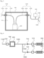
- Fig. 1 is a schematic diagram showing one embodiment of a gas collecting apparatus of the present invention.
- Fig. 2 is a cross-sectional view showing a culture flask unit 200.
- Fig. 3 is a cross-sectional view showing a constant temperature chamber 100.
- Fig. 4 is a schematic diagram showing another embodiment of a gas collecting apparatus of the present invention.
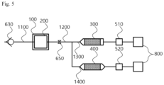
- Fig. 5 is a schematic diagram showing yet another embodiment of a gas collecting apparatus of the present invention.
- the gas collecting apparatus of the present invention may be for analyzing malodorous gases produced by bacteria cultured in a superabsorbent polymer 11.
- the malodorous gases generated by bacteria may contain various components including ammonia.
- the malodorous gases may contain ammonia and multi-odor components.
- the multi-odor components are odorous components causing a malodor among various chemical components generated by microorganisms, and may include, for example, trimethylamine of a nitrogen compound; dimethyl disulfide and dimethyl trisulfide of sulfur compounds; cresol and guaiacol of phenols; Isovaleraldehyde, pentanal, and hexanal of aldehydes; 3-methyl butanol and ethanol of alcohols; diacetyl, 2-pentanone, and 2-heptanone of ketones, and the like.
- ammonia may be collected with a gas-detecting tube or an impinger
- multi-odor components may be collected with an adsorbent tube or an impinger.
- the collection means varies depending on the types of components. Therefore, conventionally, in the case of collecting various kinds of gas components, analysis was carried out by a separate experiment for each component.
- bacteria cultured in spaces independent of each other may show reduced reproducibility between each other even if the same culture conditions are given, and there may be limitations in analyzing bacteria that generate various malodorous components with analyzing components that have been individually collected in systems independent of each other.
- the gas collecting apparatus of the present invention can carry out the analysis of various kinds of components generated in the malodorous gas accurately by quantitatively collecting and analyzing the various kinds of components contained in the malodorous gas at the same time, with a single culture in one culture space 230.
- the gas collecting apparatus of the present invention includes: a constant temperature chamber 100 inside of which is maintained at a set temperature; a culture flask unit 200 provided inside the constant temperature chamber 100 and in which bacteria are cultured; a first collecting unit 300 provided outside the constant temperature chamber 100 and configured to receive a gas from inside the culture flask unit 200; a second collecting unit 400 provided outside the constant temperature chamber 100 and configured to receive a gas from inside the culture flask unit 200; a first mass flow control unit 510 provided outside the constant temperature chamber 100 and configured to control a flow rate of the gas sucked into the first collecting unit 300; a second mass flow control unit 520 provided outside the constant temperature chamber 100 and configured to control a flow rate of the gas sucked into the second collecting unit 400; a discharge flow path 1200 with one end thereof connected to a discharge port 220 provided in the culture flask unit 200 and serving as a passage through which the gas inside the culture flask unit 200 is discharged; a first flow path 1300 having one end thereof connected
- the culture flask unit 200 is a container in which bacteria are cultured.
- the culture flask unit 200 may be provided with a culture space 230 therein, in which bacteria are cultured therein.
- the bacteria to be cultured and the superabsorbent polymer 11 may be housed in the culture space 230 of the culture flask unit 200, and the superabsorbent polymer 11 may be seated on the bottom surface of the culture space 230.
- an injection port 210 for injecting external air into the culture space 230
- a discharge port 220 for discharging the gas generated by the bacteria in the culture space 230.
- An injection flow path 1100 through which external air flows may be connected to the injection port 210 of the culture flask unit 200, and the discharge flow path 1200 through which the gas generated in the culture space 230 flows is connected to the discharge port 220 of the culture flask unit 200.
- One end of the discharge flow path 1200 may be inserted into the culture space 230 provided inside the culture flask unit 200 through the discharge port 220 formed at the top portion of the culture flask unit 200.
- the discharge flow path 1200 may extend downward in the culture space 230 and discharge the gas in the vicinity of the superabsorbent polymer 11 provided on the bottom surface of the culture space 230.
- a constant temperature space 110 in which the culture flask unit 200 is housed may be formed, a heating means capable of heating the constant temperature space 110 may be provided, and holes through which the injection flow path 1100 and the discharge flow path 1200 pass may be formed in the sidewalls.
- One side of the constant temperature chamber 100 may be formed as a door, and by opening the door, the culture flask unit 200 may be housed in the constant temperature space 110.
- a transparent window may be formed in the door, and the constant temperature space 110 can be observed from the outside of the constant temperature chamber 100 through the window.
- the first mass flow control unit 510, the second mass flow control unit 520, the first collecting unit 300, and the second collecting unit 400 are provided outside the constant temperature chamber 100 so as not to be heated by the heating means provided in the constant temperature chamber 100.
- brackets on which the first mass flow control unit 510, the second mass flow control unit 520, the first collecting unit 300, and the second collecting unit 400 are mounted may be provided on the outer wall of the constant temperature chamber 100, and the first mass flow control unit 510, the second mass flow control unit 520, the first collecting unit 300, and the second collecting unit 400 may be coupled and fixed to the outer wall of the constant temperature chamber 100 by means of the brackets.
- the constant temperature chamber 100 may have a rectangular parallelepiped shape having a plurality of planes, and the first mass flow control unit 510, the second mass flow control unit 520, the first collecting unit 300, and the second collecting unit 400 may be appropriately distributed and mounted on the outer wall surfaces of the constant temperature chamber 100.
- the wall of the constant temperature chamber 100 may be provided with a vent through which air inside and outside the constant temperature chamber 100 is vented, and a filter unit for filtering particles in the air may be provided in the vent.
- the temperature of the constant temperature space 110 of the constant temperature chamber 100 is changed by the heating means, and the air in the constant temperature space 110 can expand or contract according to the temperature change.
- the vent may be provided to maintain the pressure of the constant temperature space 110 in a certain range
- the filter unit may be provided in the vent to prevent foreign substances outside of the constant temperature chamber 100 from flowing into the constant temperature chamber 100 or components inside the constant temperature chamber 100 from being discharged to the outside of the constant temperature chamber 100 due to the air flowing in or out through the vent.
- the gas collecting apparatus of the present invention may be of a structure in which the first collecting unit 300 and the second collecting unit 400 are connected in parallel to the rear end of the culture flask unit 200 through the discharge flow path 1200, the first flow path 1300, and the second flow path 1400.
- the gas collecting apparatus of the present invention may be to collect ammonia and multi-odor components.
- a gas containing ammonia and multi-odor components generated in the culture space 230 of one culture flask unit 200 may be divided and passed through the first collecting unit 300 and the second collecting unit 400, thereby collecting ammonia and the multi-odor components contained in the gas by the first collecting unit 300 and the second collecting unit 400, respectively.
- the first collecting unit 300 may be an adsorbent tube, and the second collecting unit 400 may be an impinger or a gas-detecting tube.
- the first collecting unit 300 may collect the multi-odor components, and the second collecting unit 400 may collect ammonia.
- the adsorbent tube may be capable of adsorbing and maintaining the generated odor components in an adsorbed state for a certain period of time.
- the adsorbent tube may be provided with an adsorbent.
- the multi-odor components can be collected by the adsorbent provided in the adsorbent tube.
- the adsorbent is for collecting one or more components out of trimethylamine of a nitrogen compound; dimethyl disulfide and dimethyl trisulfide of sulfur compounds; cresol and guaiacol of phenols; Isovaleraldehyde, pentanal, and hexanal of aldehydes; 3-methyl butanol and ethanol of alcohols; diacetyl, 2-pentanone, and 2-heptanone of ketones, which are the multi-odor components described above, and may be a porous polymer adsorbent containing graphite.
- the adsorbent may be Tenax ® GR, obtained by combining 30% graphite for adsorbing low-boiling point compounds into Tenax ® TA, which is a porous polymer.
- the gas-detecting tube is a reaction tube containing a reagent used for easily and quickly measuring the concentration of a specific trace gas in a gas, and is also referred to as a gas detector.
- the concentration can be determined by the length of the colored layer of the reagent or the like produced by the reaction with a particular gas by passing a certain amount of air through the gas-detecting tube with a gas sampler.
- the gas-detecting tube may be a glass tube filled with a detecting agent (a reagent that is colored or discolored by chemical change with a gas component to be tested) adsorbed on silica gel or alumina gel particles to a length of 60 to 80 mm. Both ends of the glass tube are thinner.
- the gas may flow into one end of the glass tube and be discharged through the other end, and the ammonia component, which is the first component, may discolor the detecting agent in the process of the gas passing through the glass tube, and the remaining components may be discharged through the other end of the glass tube. Since the discoloration of the detecting agent gradually moves inward from the inlet, the concentration of the component gas to be tested can be calculated by comparing the length of this part with the concentration chart.
- the detecting agent of the second collecting unit 400 in the gas collecting apparatus of the present invention may be discolored by ammonia, and may be sulfuric acid that can directly react with ammonia gas, silica gel containing phosphoric acid and an indicator that changes color according to a change in pH, etc.
- Silica gel containing sulfuric acid (H 2 SO 4 ) or nitric acid (HNO 3 ) reacts with ammonia gas to produce ammonium sulfate or ammonium nitrate, resulting in a change in pH in this process.
- sulfuric acid H 2 SO 4
- nitric acid HNO 3
- the impinger is a kind of dust collector used to measure dust in gas, and can collect an ammonia component.
- one end of the discharge flow path 1200 is connected to the culture flask unit 200, and the other end is connected to the first flow path 1300 and the second flow path 1400. That is, the first flow path 1300 and the second flow path 1400 may be branch tubes branched from the discharge flow path 1200.
- the gas discharged through the discharge flow path 1200 may be divided into and flow in each of the first flow path 1300 and the second flow path 1400. That is, the gas of the same component may flow in the first flow path 1300 and the second flow path 1400.
- the first mass flow control unit 510 is provided on the first flow path 1300, and the second mass flow control unit 520 is provided on the second flow path 1400. That is, the first mass flow control unit 510 controls the flow rate of the gas passing through the first flow path 1300, and the second mass flow control unit 520 controls the flow rate of the gas passing through the second flow path 1400.
- the amount of gas flowing through the first collecting unit 300 and the second collecting unit 400 can be controlled independently.
- the malodor produced by the bacteria in the superabsorbent polymer 11 may contain more ammonia components than the multi-odor components. Therefore, in order for more gas to flow through the first collecting unit 300 than through the second collecting unit 400 in consideration of the detection sensitivity, the flow of the gas can be controlled through the first mass flow control unit 510 and the second mass flow control unit 520.
- the first mass flow control unit 510 and the second mass flow control unit 520 are mass flow controllers (MFCs).
- the pressure for the flow of fluids in the gas collecting apparatus of the present invention are provided by the first mass flow control unit 510 and the second mass flow control unit 520.
- the mass flow controller includes an inlet into which the fluid flows, an outlet through which the fluid is discharged, a mass flowmeter that measures the flow rate of the fluid flowing into the inlet and discharged through the outlet, a proportional valve that regulates the flow rate of the fluid flowing into the inlet and discharged through the outlet, and a controller that controls the proportional valve based on the measured values of the mass flowmeter.
- a first valve 710 may be provided at the front end of the first mass flow control unit 510 on the first flow path 1300, and a second valve 720 may be provided at the front end of the second mass flow control unit 520 on the second flow path 1400.
- the first flow path 1300 and the second flow path 1400 may be independently opened or closed via the first valve 710 and the second valve 720.
- the discharge flow path 1200 may include a first discharge flow path 1210 passing through the wall of the constant temperature chamber 100, a second discharge flow path 1220 that is a flow path connecting the discharge port 220 of the culture flask unit 200 to the first discharge flow path 1210 inside the constant temperature chamber 100, and a third discharge flow path 1230 that is a flow path connecting the first flow path 1300 and the second flow path 1400 to the first discharge flow path 1210 outside the constant temperature chamber 100.
- first discharge flow path 1210 may be provided by a stainless-steel pipe
- second discharge flow path 1220 may be provided by a Tygon tubing.
- the first discharge flow path 1210 may be a fixed structure secured to the sidewall of the constant temperature chamber 100
- the second discharge flow path 1220 may be a replaceable pipe, which may be replaced each time a new experiment starts.
- the second discharge flow path 1220 may be formed of a flexible Tygon tubing, and can thus prevent the positioning of the culture flask unit inside the constant temperature chamber 100 from being hindered by the rigidity of the second discharge flow path 1220.
- the third discharge flow path 1230 may be provided with a venting unit 640 through which the gas inside the third discharge flow path 1230 is discharged to the outside.
- a pump, a pressure tank, or the like may be connected to the injection flow path 1100, so as to apply additional pressure.
- the venting unit 640 may be provided to prevent the pressure from excessively increasing in the culture space 230, the discharge flow path 1200, the first flow path 1300, the second flow path 1400, etc.
- the venting unit 640 may be a relief valve, a check valve, or the like.
- a flow meter 620 may be provided in the injection flow path 1100, such that the air injected into the culture flask unit 200 may be quantified.
- the gas collecting apparatus of the present invention may further include an injection flow path 1100 connected to the injection port 210 provided in the culture flask unit 200 and through which air injected into the culture flask unit 200 flows; and a third mass flow control unit 610 provided in the injection flow path 1100 and configured to control the flow rate of the air injected into the culture flask unit 200. That is, the injection flow path 1100 may be provided with the third mass flow control unit 610 capable of directly controlling the flow rate of the air injected into the culture flask unit 200, instead of the flow meter 620.
- the third mass flow control unit 610 may be a mass flow controller.
- the injection flow path 1100 may include a first injection flow path 1110 passing through the wall of the constant temperature chamber 100, a second injection flow path 1120 that is a flow path connecting the injection port 210 of the culture flask unit 200 to the first injection flow path 1110 inside the constant temperature chamber 100, and a third injection flow path 1130 that is a flow path connecting the third mass flow control unit 610 located outside the constant temperature chamber 100 to the first injection flow path 1110 from outside the constant temperature chamber 100.
- first injection flow path 1110 may be provided by a stainless-steel pipe
- second injection flow path 1120 may be provided by a Tygon tubing.
- the first injection flow path 1110 may be a fixed structure secured to the sidewall of the constant temperature chamber 100
- the second injection flow path 1120 may be a replaceable pipe, which may be replaced each time a new experiment starts.
- the second injection flow path 1120 may be formed of a flexible Tygon tubing, and can thus prevent the positioning of the culture flask unit inside the constant temperature chamber 100 from being hindered by the rigidity of the second injection flow path.
- the first mass flow control unit 510 may be provided at the rear end of the first collecting unit 300
- the second mass flow control unit 520 may be provided at the rear end of the second collecting unit 400
- a vacuum pump 800 for sucking the gas in the culture flask unit 200 into the first collecting unit 300 and the second collecting unit 400 may be connected to the rear end of the first mass flow control unit 510 and the rear end of the second mass flow control unit 520. If the gas flow is guided by forming a negative pressure at the rearmost end of the gas collecting apparatus, a desired amount of gas can be collected regardless of the injection flow path 1100 side.
- the vacuum pump 800 may be a diaphragm pump.
- the gas collecting apparatus of the present invention may further include a check valve 630 provided in the injection flow path 1100 to prevent the gas inside the culture flask unit 200 from being discharged through the injection port 210 of the culture flask unit 200.
- the discharge flow path 1200 may be provided with a valve 650, so as to prevent gas from flowing backward or inadvertently spreading at the start or end of operation of the vacuum pump 800.
- the adsorbent tube is connected, together with the ammonia gas-detecting tube or the impinger in parallel, to the rear end of the culture flask unit, such that ammonia and multi-odor components can be collected simultaneously, and quantitative analysis can be possible for each of the malodorous components.
- gas collecting apparatus of the present invention can control the flow rate, collecting volume and time, etc., independently of each other for each of the first and second collecting units connected in parallel to the rear end of the culture flask unit, accurate quantitative and qualitative analysis can be possible.
- the gas collecting apparatus of the present invention is a system that ensures airtightness without leakage even in experiments conducted over a prolonged time, and thus, can collect gas components produced in real-time under the air flow by continuously supplying and discharging air.
- the gas collecting apparatus of the present invention is capable of continuously generating an air flow, and thus, can collect gas components without limitations according to the collection time regardless of the capacity of the culture flask unit.
- the gas collecting apparatus of the present invention can control and meter an accurate flow rate with mass flow control units and facilitates easy adjustment of environmental conditions such as culture time, temperature, or the like, it is possible to precisely perform quantitative analysis according to the number of cultured bacteria, and antibacterial and deodorizing treatment of the superabsorbent polymer.
Landscapes
- Health & Medical Sciences (AREA)
- Life Sciences & Earth Sciences (AREA)
- Engineering & Computer Science (AREA)
- Physics & Mathematics (AREA)
- Chemical & Material Sciences (AREA)
- Biomedical Technology (AREA)
- Molecular Biology (AREA)
- General Physics & Mathematics (AREA)
- Biochemistry (AREA)
- General Health & Medical Sciences (AREA)
- Analytical Chemistry (AREA)
- Immunology (AREA)
- Pathology (AREA)
- Biophysics (AREA)
- Hematology (AREA)
- Urology & Nephrology (AREA)
- Food Science & Technology (AREA)
- Medicinal Chemistry (AREA)
- Apparatus Associated With Microorganisms And Enzymes (AREA)
- Sampling And Sample Adjustment (AREA)
Claims (10)
- Gassammelvorrichtung, umfassend:eine Kammer mit konstanter Temperatur (100), in deren Innerem durch Heizmittel eine Solltemperatur aufrechterhalten wird;eine Kulturkolbeneinheit (200), die im Inneren der Kammer mit konstanter Temperatur (100) bereitgestellt ist und in der Bakterien kultiviert werden;eine erste Sammeleinheit (300), die außerhalb der Kammer mit konstanter Temperatur (100) bereitgestellt ist und konfiguriert ist, um ein Gas aus dem Inneren der Kulturkolbeneinheit (200) aufzunehmen;eine zweite Sammeleinheit (400), die außerhalb der Kammer mit konstanter Temperatur (100) bereitgestellt ist und konfiguriert ist, um ein Gas aus dem Inneren der Kulturkolbeneinheit (200) aufzunehmen;eine erste Massenflusssteuereinheit (510), die außerhalb der Kammer mit konstanter Temperatur (100) bereitgestellt ist und konfiguriert ist, um eine Flussrate des Gases, das in die erste Sammeleinheit (300) gesaugt wird, zu steuern;eine zweite Massenflusssteuereinheit (520), die außerhalb der Kammer mit konstanter Temperatur (100) bereitgestellt ist und konfiguriert ist, um eine Flussrate des Gases, das in die zweite Sammeleinheit (400) gesaugt wird, zu steuern;einen Abgabefließweg (1200), wobei ein Ende davon mit einer Abgabeöffnung (220) verbunden ist, die in der Kulturkolbeneinheit (200) bereitgestellt ist und als ein Durchgang dient, durch den das Gas im Inneren der Kulturkolbeneinheit (200) abgegeben wird;einen ersten Fließweg (1300), wobei ein Ende davon mit dem anderen Ende des Abgabefließwegs (1200) verbunden ist und das andere Ende davon mit der ersten Sammeleinheit (300) verbunden ist; undeinen zweiten Fließweg (1400), wobei ein Ende davon mit dem anderen Ende des Abgabefließwegs (1200) zusammen mit dem ersten Fließweg (1300) verbunden ist und das andere Ende davon mit der zweiten Sammeleinheit (400) verbunden ist,wobei die erste Massenflusssteuereinheit (510) auf dem ersten Fließweg (1300) bereitgestellt ist, unddie zweite Massenflusssteuereinheit (520) auf dem zweiten Fließweg (1400) bereitgestellt ist.
- Gassammelvorrichtung nach Anspruch 1, bei der die erste Sammeleinheit (300) ein Adsorptionsmittelrohr ist, und
die zweite Sammeleinheit (400) ein Prallrohr oder ein Gaserfassungsrohr ist. - Gassammelvorrichtung nach Anspruch 1, bei der ein erstes Ventil (710) an einem vorderen Ende der ersten Massenflusssteuereinheit (510) auf dem ersten Fließweg (1300) bereitgestellt ist, und
ein zweites Ventil (720) an einem vorderen Ende der zweiten Massenflusssteuereinheit (520) auf dem zweiten Fließweg (1400) bereitgestellt ist. - Gassammelvorrichtung nach Anspruch 1, bei der der Abgabefließweg (1200) umfasst:einen ersten Abgabefließweg (1210), der durch eine Wand der Kammer mit konstanter Temperatur (100) verläuft;einen zweiten Abgabefließweg (1220), der ein Fließweg ist, der die Abgabeöffnung (220) der Kulturkolbeneinheit (200) mit dem ersten Abgabefließweg (1210) im Inneren der Kammer mit konstanter Temperatur (100) verbindet; undeinen dritten Abgabefließweg (1230), der ein Fließweg ist, der den ersten Fließweg (1300) und den zweiten Fließweg (1400) mit dem ersten Abgabefließweg außerhalb der Kammer mit konstanter Temperatur verbindet.
- Gassammelvorrichtung nach Anspruch 4, bei der der dritte Abgabefließweg (1230) mit einer Entlüftungseinheit (640) versehen ist, durch die ein Gas im Inneren des dritten Abgabefließwegs (1230) nach außen abgegeben wird.
- Gassammelvorrichtung nach Anspruch 1, ferner umfassend:einen Injektionsfließweg (1100), der mit einer Injektionsöffnung (210) verbunden ist, die in der Kulturkolbeneinheit (200) bereitgestellt ist und durch den Luft fließt, die in die Kulturkolbeneinheit (200) injiziert wird; undeine dritte Massenflusssteuereinheit (610), die in dem Injektionsfließweg (1100) bereitgestellt ist und konfiguriert ist, um eine Flussrate der Luft, die in die Kulturkolbeneinheit (200) injiziert wird, zu steuern.
- Gassammelvorrichtung nach Anspruch 6, bei der der Injektionsfließweg (1100) umfasst:einen ersten Injektionsfließweg (1110), der durch eine Wand der Kammer mit konstanter Temperatur (100) verläuft;einen zweiten Injektionsfließweg (1120), der ein Fließweg ist, der die Injektionsöffnung (210) der Kulturkolbeneinheit (200) mit dem ersten Injektionsfließweg (1110) im Inneren der Kammer mit konstanter Temperatur (100) verbindet; undeinen dritten Injektionsfließweg (1130), der ein Fließweg ist, der die dritte Massenflusssteuereinheit (610), die außerhalb der Kammer mit konstanter Temperatur (100) angeordnet ist, mit dem ersten Injektionsfließweg (1110) außerhalb der Kammer mit konstanter Temperatur (100) verbindet.
- Gassammelvorrichtung nach Anspruch 2, bei der die erste Massenflusssteuereinheit (510) an einem hinteren Ende der ersten Sammeleinheit (300) bereitgestellt ist,die zweite Massenflusssteuereinheit (520) an einem hinteren Ende der zweiten Sammeleinheit (400) bereitgestellt ist, undeine Vakuumpumpe (800) zum Saugen des Gases in der Kulturkolbeneinheit (200) in die erste Sammeleinheit (300) und die zweite Sammeleinheit (400) mit dem hinteren Ende der ersten Massenflusssteuereinheit (510) und dem hinteren Ende der zweiten Massenflusssteuereinheit (520) verbunden ist.
- Gassammelvorrichtung nach Anspruch 8, bei der die Vakuumpumpe (800) eine Membranpumpe ist.
- Gassammelvorrichtung nach Anspruch 8, ferner umfassend:einen Injektionsfließweg (1100), der mit einer Injektionsöffnung (210) verbunden ist, die in der Kulturkolbeneinheit (200) bereitgestellt ist und durch den Luft fließt, die in die Kulturkolbeneinheit (200) injiziert wird; undein Rückschlagventil (630), das in dem Injektionsfließweg (1100) bereitgestellt ist, um zu verhindern, dass das Gas im Inneren der Kulturkolbeneinheit (200) durch die Injektionsöffnung (210) der Kulturkolbeneinheit (200) abgegeben wird.
Applications Claiming Priority (2)
| Application Number | Priority Date | Filing Date | Title |
|---|---|---|---|
| KR1020200149226A KR102738055B1 (ko) | 2020-11-10 | 2020-11-10 | 가스 포집 장치 |
| PCT/KR2021/011773 WO2022102924A1 (ko) | 2020-11-10 | 2021-09-01 | 가스 포집 장치 |
Publications (3)
| Publication Number | Publication Date |
|---|---|
| EP4098994A1 EP4098994A1 (de) | 2022-12-07 |
| EP4098994A4 EP4098994A4 (de) | 2023-10-04 |
| EP4098994B1 true EP4098994B1 (de) | 2025-06-18 |
Family
ID=81601483
Family Applications (1)
| Application Number | Title | Priority Date | Filing Date |
|---|---|---|---|
| EP21892094.0A Active EP4098994B1 (de) | 2020-11-10 | 2021-09-01 | Gassammelvorrichtung |
Country Status (6)
| Country | Link |
|---|---|
| US (1) | US12571707B2 (de) |
| EP (1) | EP4098994B1 (de) |
| JP (1) | JP7364304B2 (de) |
| KR (1) | KR102738055B1 (de) |
| CN (1) | CN115210552A (de) |
| WO (1) | WO2022102924A1 (de) |
Families Citing this family (1)
| Publication number | Priority date | Publication date | Assignee | Title |
|---|---|---|---|---|
| KR102866758B1 (ko) * | 2023-06-15 | 2025-09-30 | 한국원자력연구원 | 공기포집기 |
Citations (1)
| Publication number | Priority date | Publication date | Assignee | Title |
|---|---|---|---|---|
| JP2005269921A (ja) * | 2004-03-23 | 2005-10-06 | Taitec Corp | 細胞や組織等の試料の恒温振とうによる培養方法とその装置 |
Family Cites Families (28)
| Publication number | Priority date | Publication date | Assignee | Title |
|---|---|---|---|---|
| JPH02115743A (ja) | 1988-10-25 | 1990-04-27 | Kurita Water Ind Ltd | 臭気ガス計測装置 |
| BE1004508A3 (nl) * | 1991-02-01 | 1992-12-01 | Organic Waste Systems Nv | Werkwijze en inrichting voor het bepalen van de aerobe biologische afbreekbaarheid. |
| JPH06341984A (ja) * | 1993-06-03 | 1994-12-13 | Toyota Motor Corp | 塗料評価方法 |
| JPH08145971A (ja) * | 1994-11-21 | 1996-06-07 | Tokico Ltd | 金属成分分析装置 |
| JP3755251B2 (ja) * | 1996-08-09 | 2006-03-15 | 三菱電機株式会社 | におい測定装置 |
| JPH09170995A (ja) | 1996-12-13 | 1997-06-30 | Fuji Electric Co Ltd | 油中可燃性ガス検出装置 |
| US6673595B2 (en) * | 2001-08-27 | 2004-01-06 | Biocrystal, Ltd | Automated cell management system for growth and manipulation of cultured cells |
| CN1164758C (zh) | 2001-09-05 | 2004-09-01 | 中国科学院过程工程研究所 | 采用气升式发酵分离耦合技术制备酒精的方法和专用设备 |
| JP2003130860A (ja) * | 2001-10-19 | 2003-05-08 | Asahi Kasei Corp | 揮発性物質自動分析装置 |
| JP2004132879A (ja) * | 2002-10-11 | 2004-04-30 | National Cardiovascular Center | 高感度ガス分析システムおよびそれを用いたガス分析方法 |
| KR100523560B1 (ko) * | 2003-04-11 | 2005-10-25 | 학교법인 한양학원 | 오염물질을 측정하기 위한 오염물질 포집장치 및 방법 |
| KR100525515B1 (ko) | 2004-02-27 | 2005-11-02 | 장기호 | 건축자재 유해물질 측정용 시험기 |
| KR100737132B1 (ko) * | 2006-06-14 | 2007-07-06 | 대한주택공사 | 바탕챔버를 이용한 건축자재 방출 유해물질 측정방법 및 그장치 |
| JP2010049763A (ja) * | 2008-08-22 | 2010-03-04 | Toshiba Storage Device Corp | 有機ガスの透過性評価方法および透過性評価装置 |
| JP5146264B2 (ja) * | 2008-11-04 | 2013-02-20 | 株式会社島津製作所 | 気体試料導入装置及びそれを備えたガスクロマトグラフ装置 |
| EP2470221B1 (de) | 2009-08-26 | 2016-03-23 | Basf Se | Geruchsinhibierende zusammensetzungen |
| JP2013200226A (ja) | 2012-03-26 | 2013-10-03 | Bridgestone Corp | 植物放出ガス捕集装置、植物放出ガス分析装置および植物放出ガス分析方法 |
| KR101250898B1 (ko) * | 2012-10-17 | 2013-04-05 | 김중구 | 이동식 악취 샘플링장치 |
| JP6066405B2 (ja) | 2012-12-17 | 2017-01-25 | 株式会社竹中工務店 | 油汚染土壌用定量測定システム |
| FR3010482B1 (fr) | 2013-09-12 | 2015-10-16 | Air Liquide | Dispositif d'echantillonnage de gaz et station de remplissage comprenant un tel dispositif |
| WO2015056302A1 (ja) * | 2013-10-15 | 2015-04-23 | 株式会社日立製作所 | 細胞培養装置 |
| GB201409045D0 (en) * | 2014-05-21 | 2014-07-02 | Univ Cranfield | Detection of bacterial infection |
| KR101808405B1 (ko) | 2016-02-04 | 2017-12-14 | 한국과학기술연구원 | 고효율의 다량 기상합성 나노입자 자동제어 포집장치 및 그 포집방법 |
| JP6682088B2 (ja) | 2016-04-27 | 2020-04-15 | 国立研究開発法人産業技術総合研究所 | ガス状水銀又はスチビンの測定方法及び測定装置 |
| CN106701547A (zh) * | 2016-12-26 | 2017-05-24 | 浙江海洋大学 | 生物代谢产生的气体挥发物的收集装置及其实时采集方法 |
| CN112384809B (zh) * | 2018-04-07 | 2025-09-23 | 路玛赛特有限责任公司 | 流体自动采样器和培育器 |
| KR102015227B1 (ko) * | 2018-11-09 | 2019-08-27 | 건국대학교 산학협력단 | 열탈착부와 ndir부를 갖는 콤팩트형 배출가스 분석장치 및 그 분석방법 |
| DE102018131184A1 (de) | 2018-12-06 | 2020-06-10 | Adolf Kühner Ag | Begasungsvorrichtung |
-
2020
- 2020-11-10 KR KR1020200149226A patent/KR102738055B1/ko active Active
-
2021
- 2021-09-01 JP JP2022554245A patent/JP7364304B2/ja active Active
- 2021-09-01 EP EP21892094.0A patent/EP4098994B1/de active Active
- 2021-09-01 CN CN202180018453.5A patent/CN115210552A/zh active Pending
- 2021-09-01 WO PCT/KR2021/011773 patent/WO2022102924A1/ko not_active Ceased
- 2021-09-01 US US17/922,462 patent/US12571707B2/en active Active
Patent Citations (1)
| Publication number | Priority date | Publication date | Assignee | Title |
|---|---|---|---|---|
| JP2005269921A (ja) * | 2004-03-23 | 2005-10-06 | Taitec Corp | 細胞や組織等の試料の恒温振とうによる培養方法とその装置 |
Non-Patent Citations (2)
| Title |
|---|
| FILIPIAK WOJCIECH ET AL: "Breath analysis for in vivo detection of pathogens related to ventilator-associated pneumonia in intensive care patients: a prospective pilot study", JOURNAL OF BREATH RESEARCH IOP PUBLISHING LTD. UK, vol. 9, no. 1, 5 January 2015 (2015-01-05), pages 016004, XP093138634, ISSN: 1752-7163, DOI: 10.1088/1752-7155/9/1/016004 * |
| FILIPIAK WOJCIECH ET AL: "Characterization of volatile metabolites taken up by or released from Streptococcus pneumoniae and Haemophilus influenzae by using GC-MS", MICROBIOLOGY, vol. 158, no. 12, 1 December 2012 (2012-12-01), Reading, pages 3044 - 3053, XP093138633, ISSN: 1350-0872, DOI: 10.1099/mic.0.062687-0 * |
Also Published As
| Publication number | Publication date |
|---|---|
| KR20220063408A (ko) | 2022-05-17 |
| JP2023516780A (ja) | 2023-04-20 |
| US12571707B2 (en) | 2026-03-10 |
| US20230168159A1 (en) | 2023-06-01 |
| KR102738055B1 (ko) | 2024-12-04 |
| WO2022102924A1 (ko) | 2022-05-19 |
| JP7364304B2 (ja) | 2023-10-18 |
| CN115210552A (zh) | 2022-10-18 |
| EP4098994A1 (de) | 2022-12-07 |
| EP4098994A4 (de) | 2023-10-04 |
Similar Documents
| Publication | Publication Date | Title |
|---|---|---|
| TWI833984B (zh) | 觸發式採樣系統及方法 | |
| US20100223979A1 (en) | Systems and Methods for Measurement of Gas Permeation Through Polymer Films | |
| CN208043616U (zh) | 一种粒子分析仪及其液路系统 | |
| US12571707B2 (en) | Gas collection device | |
| CN106996965B (zh) | 稻米霉菌在线监测系统、建立方法及应用 | |
| WO2019010390A1 (en) | ELECTRONIC MICROSCOPE SAMPLE HOLDER FLUID MANAGEMENT WITH INDEPENDENT PRESSURE AND FLOW CONTROL | |
| ES2968103T3 (es) | Espectrómetro de masas en línea para la detección en tiempo real de componentes volátiles de la fase gaseosa y líquida para el análisis de procesos | |
| KR102924387B1 (ko) | 가스 포집 장치 | |
| US20120247188A1 (en) | Gas Sample Collection and Analysis | |
| EP3933024B1 (de) | Gassammelvorrichtung | |
| KR102635616B1 (ko) | 가스 포집 장치 | |
| CN207067075U (zh) | 稻米霉菌在线监测系统 | |
| US20080142456A1 (en) | Method and system for collecting cells of a biological specimen | |
| CN212341122U (zh) | 一种外场测定植物BVOCs排放的半开放式动态箱系统 | |
| CN208350822U (zh) | 液体化工产品微水进样装置 | |
| CN109164837B (zh) | 流量恒定装置及其使用方法、快速分析仪器及其检测方法 | |
| KR102553667B1 (ko) | 가스 포집 장치 | |
| Bohátka | Quadrupole mass spectrometric measurement of dissolved and free gases | |
| US20220002648A1 (en) | Gas Collection Device | |
| KR102536296B1 (ko) | 반휘발성 유기화합물의 특성평가를 위한 듀얼챔버 | |
| SU1010130A1 (ru) | Способ определени количества газов в процессе культивировани микроорганизмов | |
| Fukui et al. | Determination of alcohol in liquid samples by means of an infrared gas analyzer | |
| CN112014503A (zh) | 一种有组织废气中乙腈的检测方法 | |
| JP2008298423A (ja) | 気体試料採取装置 | |
| CN114324777A (zh) | 流水线实时精准微量水分测定方法及装置 |
Legal Events
| Date | Code | Title | Description |
|---|---|---|---|
| STAA | Information on the status of an ep patent application or granted ep patent |
Free format text: STATUS: THE INTERNATIONAL PUBLICATION HAS BEEN MADE |
|
| PUAI | Public reference made under article 153(3) epc to a published international application that has entered the european phase |
Free format text: ORIGINAL CODE: 0009012 |
|
| STAA | Information on the status of an ep patent application or granted ep patent |
Free format text: STATUS: REQUEST FOR EXAMINATION WAS MADE |
|
| 17P | Request for examination filed |
Effective date: 20220902 |
|
| AK | Designated contracting states |
Kind code of ref document: A1 Designated state(s): AL AT BE BG CH CY CZ DE DK EE ES FI FR GB GR HR HU IE IS IT LI LT LU LV MC MK MT NL NO PL PT RO RS SE SI SK SM TR |
|
| A4 | Supplementary search report drawn up and despatched |
Effective date: 20230906 |
|
| RIC1 | Information provided on ipc code assigned before grant |
Ipc: C12M 1/107 20060101ALI20230831BHEP Ipc: G01N 1/40 20060101ALI20230831BHEP Ipc: G01N 33/497 20060101ALI20230831BHEP Ipc: G01N 1/22 20060101ALI20230831BHEP Ipc: G01N 1/24 20060101AFI20230831BHEP |
|
| DAV | Request for validation of the european patent (deleted) | ||
| DAX | Request for extension of the european patent (deleted) | ||
| STAA | Information on the status of an ep patent application or granted ep patent |
Free format text: STATUS: EXAMINATION IS IN PROGRESS |
|
| 17Q | First examination report despatched |
Effective date: 20240320 |
|
| GRAP | Despatch of communication of intention to grant a patent |
Free format text: ORIGINAL CODE: EPIDOSNIGR1 |
|
| STAA | Information on the status of an ep patent application or granted ep patent |
Free format text: STATUS: GRANT OF PATENT IS INTENDED |
|
| RAP3 | Party data changed (applicant data changed or rights of an application transferred) |
Owner name: LG CHEM, LTD. |
|
| INTG | Intention to grant announced |
Effective date: 20250317 |
|
| GRAS | Grant fee paid |
Free format text: ORIGINAL CODE: EPIDOSNIGR3 |
|
| GRAA | (expected) grant |
Free format text: ORIGINAL CODE: 0009210 |
|
| STAA | Information on the status of an ep patent application or granted ep patent |
Free format text: STATUS: THE PATENT HAS BEEN GRANTED |
|
| AK | Designated contracting states |
Kind code of ref document: B1 Designated state(s): AL AT BE BG CH CY CZ DE DK EE ES FI FR GB GR HR HU IE IS IT LI LT LU LV MC MK MT NL NO PL PT RO RS SE SI SK SM TR |
|
| REG | Reference to a national code |
Ref country code: GB Ref legal event code: FG4D |
|
| REG | Reference to a national code |
Ref country code: CH Ref legal event code: EP |
|
| REG | Reference to a national code |
Ref country code: DE Ref legal event code: R096 Ref document number: 602021032615 Country of ref document: DE |
|
| REG | Reference to a national code |
Ref country code: CH Ref legal event code: EP |
|
| REG | Reference to a national code |
Ref country code: IE Ref legal event code: FG4D |
|
| PG25 | Lapsed in a contracting state [announced via postgrant information from national office to epo] |
Ref country code: FI Free format text: LAPSE BECAUSE OF FAILURE TO SUBMIT A TRANSLATION OF THE DESCRIPTION OR TO PAY THE FEE WITHIN THE PRESCRIBED TIME-LIMIT Effective date: 20250618 |
|
| PGFP | Annual fee paid to national office [announced via postgrant information from national office to epo] |
Ref country code: DE Payment date: 20250820 Year of fee payment: 5 |
|
| REG | Reference to a national code |
Ref country code: LT Ref legal event code: MG9D |
|
| PG25 | Lapsed in a contracting state [announced via postgrant information from national office to epo] |
Ref country code: GR Free format text: LAPSE BECAUSE OF FAILURE TO SUBMIT A TRANSLATION OF THE DESCRIPTION OR TO PAY THE FEE WITHIN THE PRESCRIBED TIME-LIMIT Effective date: 20250919 Ref country code: NO Free format text: LAPSE BECAUSE OF FAILURE TO SUBMIT A TRANSLATION OF THE DESCRIPTION OR TO PAY THE FEE WITHIN THE PRESCRIBED TIME-LIMIT Effective date: 20250918 |
|
| PG25 | Lapsed in a contracting state [announced via postgrant information from national office to epo] |
Ref country code: BG Free format text: LAPSE BECAUSE OF FAILURE TO SUBMIT A TRANSLATION OF THE DESCRIPTION OR TO PAY THE FEE WITHIN THE PRESCRIBED TIME-LIMIT Effective date: 20250618 |
|
| PGFP | Annual fee paid to national office [announced via postgrant information from national office to epo] |
Ref country code: BE Payment date: 20250821 Year of fee payment: 5 Ref country code: GB Payment date: 20250820 Year of fee payment: 5 |
|
| PG25 | Lapsed in a contracting state [announced via postgrant information from national office to epo] |
Ref country code: HR Free format text: LAPSE BECAUSE OF FAILURE TO SUBMIT A TRANSLATION OF THE DESCRIPTION OR TO PAY THE FEE WITHIN THE PRESCRIBED TIME-LIMIT Effective date: 20250618 |
|
| PGFP | Annual fee paid to national office [announced via postgrant information from national office to epo] |
Ref country code: AT Payment date: 20251020 Year of fee payment: 5 Ref country code: FR Payment date: 20250821 Year of fee payment: 5 |
|
| PG25 | Lapsed in a contracting state [announced via postgrant information from national office to epo] |
Ref country code: RS Free format text: LAPSE BECAUSE OF FAILURE TO SUBMIT A TRANSLATION OF THE DESCRIPTION OR TO PAY THE FEE WITHIN THE PRESCRIBED TIME-LIMIT Effective date: 20250918 |
|
| REG | Reference to a national code |
Ref country code: NL Ref legal event code: MP Effective date: 20250618 |
|
| PG25 | Lapsed in a contracting state [announced via postgrant information from national office to epo] |
Ref country code: LV Free format text: LAPSE BECAUSE OF FAILURE TO SUBMIT A TRANSLATION OF THE DESCRIPTION OR TO PAY THE FEE WITHIN THE PRESCRIBED TIME-LIMIT Effective date: 20250618 |
|
| PG25 | Lapsed in a contracting state [announced via postgrant information from national office to epo] |
Ref country code: NL Free format text: LAPSE BECAUSE OF FAILURE TO SUBMIT A TRANSLATION OF THE DESCRIPTION OR TO PAY THE FEE WITHIN THE PRESCRIBED TIME-LIMIT Effective date: 20250618 |
|
| PG25 | Lapsed in a contracting state [announced via postgrant information from national office to epo] |
Ref country code: PT Free format text: LAPSE BECAUSE OF FAILURE TO SUBMIT A TRANSLATION OF THE DESCRIPTION OR TO PAY THE FEE WITHIN THE PRESCRIBED TIME-LIMIT Effective date: 20251020 |
|
| REG | Reference to a national code |
Ref country code: AT Ref legal event code: MK05 Ref document number: 1804574 Country of ref document: AT Kind code of ref document: T Effective date: 20250618 |
|
| PG25 | Lapsed in a contracting state [announced via postgrant information from national office to epo] |
Ref country code: IS Free format text: LAPSE BECAUSE OF FAILURE TO SUBMIT A TRANSLATION OF THE DESCRIPTION OR TO PAY THE FEE WITHIN THE PRESCRIBED TIME-LIMIT Effective date: 20251018 |
|
| PG25 | Lapsed in a contracting state [announced via postgrant information from national office to epo] |
Ref country code: AT Free format text: LAPSE BECAUSE OF FAILURE TO SUBMIT A TRANSLATION OF THE DESCRIPTION OR TO PAY THE FEE WITHIN THE PRESCRIBED TIME-LIMIT Effective date: 20250618 Ref country code: SM Free format text: LAPSE BECAUSE OF FAILURE TO SUBMIT A TRANSLATION OF THE DESCRIPTION OR TO PAY THE FEE WITHIN THE PRESCRIBED TIME-LIMIT Effective date: 20250618 |
|
| PG25 | Lapsed in a contracting state [announced via postgrant information from national office to epo] |
Ref country code: CZ Free format text: LAPSE BECAUSE OF FAILURE TO SUBMIT A TRANSLATION OF THE DESCRIPTION OR TO PAY THE FEE WITHIN THE PRESCRIBED TIME-LIMIT Effective date: 20250618 |
|
| PG25 | Lapsed in a contracting state [announced via postgrant information from national office to epo] |
Ref country code: PL Free format text: LAPSE BECAUSE OF FAILURE TO SUBMIT A TRANSLATION OF THE DESCRIPTION OR TO PAY THE FEE WITHIN THE PRESCRIBED TIME-LIMIT Effective date: 20250618 |
|
| PG25 | Lapsed in a contracting state [announced via postgrant information from national office to epo] |
Ref country code: EE Free format text: LAPSE BECAUSE OF FAILURE TO SUBMIT A TRANSLATION OF THE DESCRIPTION OR TO PAY THE FEE WITHIN THE PRESCRIBED TIME-LIMIT Effective date: 20250618 |
|
| PG25 | Lapsed in a contracting state [announced via postgrant information from national office to epo] |
Ref country code: SK Free format text: LAPSE BECAUSE OF FAILURE TO SUBMIT A TRANSLATION OF THE DESCRIPTION OR TO PAY THE FEE WITHIN THE PRESCRIBED TIME-LIMIT Effective date: 20250618 |
|
| PG25 | Lapsed in a contracting state [announced via postgrant information from national office to epo] |
Ref country code: ES Free format text: LAPSE BECAUSE OF FAILURE TO SUBMIT A TRANSLATION OF THE DESCRIPTION OR TO PAY THE FEE WITHIN THE PRESCRIBED TIME-LIMIT Effective date: 20250618 |
|
| PG25 | Lapsed in a contracting state [announced via postgrant information from national office to epo] |
Ref country code: RO Free format text: LAPSE BECAUSE OF FAILURE TO SUBMIT A TRANSLATION OF THE DESCRIPTION OR TO PAY THE FEE WITHIN THE PRESCRIBED TIME-LIMIT Effective date: 20250618 |
|
| REG | Reference to a national code |
Ref country code: DE Ref legal event code: R097 Ref document number: 602021032615 Country of ref document: DE |
|
| PG25 | Lapsed in a contracting state [announced via postgrant information from national office to epo] |
Ref country code: DK Free format text: LAPSE BECAUSE OF FAILURE TO SUBMIT A TRANSLATION OF THE DESCRIPTION OR TO PAY THE FEE WITHIN THE PRESCRIBED TIME-LIMIT Effective date: 20250618 |
|
| PG25 | Lapsed in a contracting state [announced via postgrant information from national office to epo] |
Ref country code: IT Free format text: LAPSE BECAUSE OF FAILURE TO SUBMIT A TRANSLATION OF THE DESCRIPTION OR TO PAY THE FEE WITHIN THE PRESCRIBED TIME-LIMIT Effective date: 20250618 |
|
| PLBE | No opposition filed within time limit |
Free format text: ORIGINAL CODE: 0009261 |
|
| STAA | Information on the status of an ep patent application or granted ep patent |
Free format text: STATUS: NO OPPOSITION FILED WITHIN TIME LIMIT |
|
| REG | Reference to a national code |
Ref country code: CH Ref legal event code: L10 Free format text: ST27 STATUS EVENT CODE: U-0-0-L10-L00 (AS PROVIDED BY THE NATIONAL OFFICE) Effective date: 20260430 |
|
| REG | Reference to a national code |
Ref country code: CH Ref legal event code: H13 Free format text: ST27 STATUS EVENT CODE: U-0-0-H10-H13 (AS PROVIDED BY THE NATIONAL OFFICE) Effective date: 20260504 |