EP4098832A1 - Baugruppe zur anordnung an einer bandseite eines flügels eines fensters oder einer tür - Google Patents
Baugruppe zur anordnung an einer bandseite eines flügels eines fensters oder einer tür Download PDFInfo
- Publication number
- EP4098832A1 EP4098832A1 EP21177455.9A EP21177455A EP4098832A1 EP 4098832 A1 EP4098832 A1 EP 4098832A1 EP 21177455 A EP21177455 A EP 21177455A EP 4098832 A1 EP4098832 A1 EP 4098832A1
- Authority
- EP
- European Patent Office
- Prior art keywords
- section
- assembly
- adjusting screw
- fitting part
- intermediate section
- Prior art date
- Legal status (The legal status is an assumption and is not a legal conclusion. Google has not performed a legal analysis and makes no representation as to the accuracy of the status listed.)
- Granted
Links
Images




Classifications
-
- E—FIXED CONSTRUCTIONS
- E05—LOCKS; KEYS; WINDOW OR DOOR FITTINGS; SAFES
- E05D—HINGES OR SUSPENSION DEVICES FOR DOORS, WINDOWS OR WINGS
- E05D7/00—Hinges or pivots of special construction
- E05D7/0009—Adjustable hinges
- E05D7/0018—Adjustable hinges at the hinge axis
- E05D7/0027—Adjustable hinges at the hinge axis in an axial direction
-
- E—FIXED CONSTRUCTIONS
- E05—LOCKS; KEYS; WINDOW OR DOOR FITTINGS; SAFES
- E05D—HINGES OR SUSPENSION DEVICES FOR DOORS, WINDOWS OR WINGS
- E05D15/00—Suspension arrangements for wings
- E05D15/48—Suspension arrangements for wings allowing alternative movements
- E05D15/52—Suspension arrangements for wings allowing alternative movements for opening about a vertical as well as a horizontal axis
- E05D15/5214—Corner supports
-
- E—FIXED CONSTRUCTIONS
- E05—LOCKS; KEYS; WINDOW OR DOOR FITTINGS; SAFES
- E05D—HINGES OR SUSPENSION DEVICES FOR DOORS, WINDOWS OR WINGS
- E05D5/00—Construction of single parts, e.g. the parts for attachment
- E05D5/10—Pins, sockets or sleeves; Removable pins
- E05D5/14—Construction of sockets or sleeves
-
- E—FIXED CONSTRUCTIONS
- E05—LOCKS; KEYS; WINDOW OR DOOR FITTINGS; SAFES
- E05D—HINGES OR SUSPENSION DEVICES FOR DOORS, WINDOWS OR WINGS
- E05D7/00—Hinges or pivots of special construction
- E05D7/0009—Adjustable hinges
- E05D7/0018—Adjustable hinges at the hinge axis
- E05D7/0027—Adjustable hinges at the hinge axis in an axial direction
- E05D2007/0036—Adjustable hinges at the hinge axis in an axial direction with axially fixed hinge pins
-
- E—FIXED CONSTRUCTIONS
- E05—LOCKS; KEYS; WINDOW OR DOOR FITTINGS; SAFES
- E05Y—INDEXING SCHEME ASSOCIATED WITH SUBCLASSES E05D AND E05F, RELATING TO CONSTRUCTION ELEMENTS, ELECTRIC CONTROL, POWER SUPPLY, POWER SIGNAL OR TRANSMISSION, USER INTERFACES, MOUNTING OR COUPLING, DETAILS, ACCESSORIES, AUXILIARY OPERATIONS NOT OTHERWISE PROVIDED FOR, APPLICATION THEREOF
- E05Y2600/00—Mounting or coupling arrangements for elements provided for in this subclass
- E05Y2600/50—Mounting methods; Positioning
- E05Y2600/56—Positioning, e.g. re-positioning, or pre-mounting
-
- E—FIXED CONSTRUCTIONS
- E05—LOCKS; KEYS; WINDOW OR DOOR FITTINGS; SAFES
- E05Y—INDEXING SCHEME ASSOCIATED WITH SUBCLASSES E05D AND E05F, RELATING TO CONSTRUCTION ELEMENTS, ELECTRIC CONTROL, POWER SUPPLY, POWER SIGNAL OR TRANSMISSION, USER INTERFACES, MOUNTING OR COUPLING, DETAILS, ACCESSORIES, AUXILIARY OPERATIONS NOT OTHERWISE PROVIDED FOR, APPLICATION THEREOF
- E05Y2800/00—Details, accessories and auxiliary operations not otherwise provided for
- E05Y2800/20—Combinations of elements
-
- E—FIXED CONSTRUCTIONS
- E05—LOCKS; KEYS; WINDOW OR DOOR FITTINGS; SAFES
- E05Y—INDEXING SCHEME ASSOCIATED WITH SUBCLASSES E05D AND E05F, RELATING TO CONSTRUCTION ELEMENTS, ELECTRIC CONTROL, POWER SUPPLY, POWER SIGNAL OR TRANSMISSION, USER INTERFACES, MOUNTING OR COUPLING, DETAILS, ACCESSORIES, AUXILIARY OPERATIONS NOT OTHERWISE PROVIDED FOR, APPLICATION THEREOF
- E05Y2800/00—Details, accessories and auxiliary operations not otherwise provided for
- E05Y2800/67—Materials; Strength alteration thereof
- E05Y2800/684—Strength alteration by weakening, e.g. by applying grooves
-
- E—FIXED CONSTRUCTIONS
- E05—LOCKS; KEYS; WINDOW OR DOOR FITTINGS; SAFES
- E05Y—INDEXING SCHEME ASSOCIATED WITH SUBCLASSES E05D AND E05F, RELATING TO CONSTRUCTION ELEMENTS, ELECTRIC CONTROL, POWER SUPPLY, POWER SIGNAL OR TRANSMISSION, USER INTERFACES, MOUNTING OR COUPLING, DETAILS, ACCESSORIES, AUXILIARY OPERATIONS NOT OTHERWISE PROVIDED FOR, APPLICATION THEREOF
- E05Y2900/00—Application of doors, windows, wings or fittings thereof
- E05Y2900/10—Application of doors, windows, wings or fittings thereof for buildings or parts thereof
- E05Y2900/13—Type of wing
- E05Y2900/148—Windows
Definitions
- the invention relates to an assembly for arrangement on a hinge side of a sash of a window or a door, with a fitting part for attachment to the sash, the fitting part having a receiving space for rotatably receiving at least the front end of a frame of the window or door or having arranged bearing bolt and wherein the fitting part is provided with an adjustment screw movable along an adjustment axis for adjusting a position of the fitting part relative to the bearing bolt.
- Assemblies of the aforementioned type are also known as "corner bearings". They are used to rotate the sash of a window or door about an axis of rotation relative to a fixed frame. In order to allow a height adjustment of the wing relative to the frame, an adjustment screw is provided with is screwed to the fitting part and can assume different positions along an adjustment axis.
- an arrangement for mounting a bearing bolt with a bearing sleeve in which the bearing bolt is arranged, with a front end of the adjusting screw resting on a front end of the bearing bolt.
- an anti-twist device is provided for the adjusting screw, with a web which is integrally connected to the bearing sleeve and protrudes into a threaded section of the adjusting screw.
- the object of the present invention is to propose an alternative structure for an assembly.
- an additional part with an intermediate section and a securing section, the intermediate section being designed to be arranged between a front end of the adjusting screw and the front end of the bearing bolt, the securing section being designed to engage in an external thread of the Adjusting screw is formed and secured against rotation on the fitting part, the intermediate section and the securing section being connected to one another in a pre-assembly state of the additional part and the intermediate section being separated from the securing section and together in an assembled state of the additional part is movable with the adjustment screw along the adjustment axis.
- the assembly according to the invention makes it possible to dispense with a bearing sleeve known from the prior art.
- the assembly according to the invention allows a simple and quick assembly of a sash on a frame and a simple and quick adjustment of the height of the sash and also a reliable safeguard against unwanted adjustment of the height of the sash.
- the weight of the wing is introduced via the fitting into the adjusting screw and from there into the intermediate section.
- the weight of the components mentioned above is supported on the frame-side bearing bolt.
- the intermediate section is connected to a securing section, so that the securing section can initially be handled together with the intermediate section when the assembly is assembled.
- the securing section In an assembled state, the securing section is separated from the intermediate section and engages in an external thread of the adjusting screw and is at the same time secured against rotation on the fitting part.
- the engagement of the external thread of the adjusting screw in the securing section is based on a pre-assembly state of the additional part preferably accompanied by the fact that the Adjusting screw with its external thread cuts or imprints an internal thread in a surface portion of the securing portion.
- the securing section has the effect that although the adjusting screw can still be rotated relative to the fitting part, the anti-rotation effect of the securing section must be overcome for this purpose.
- the adjusting screw After detachment of the securing portion from the intermediate portion, the adjusting screw is movable together with the intermediate portion relative to the fitting along the adjustment axis independently of the securing portion (separated in this state).
- a transition from the pre-assembly state to the assembly state is accompanied by the front end of the adjusting screw coming into contact with a contact surface of the intermediate section when the adjusting screw is screwed into an internal thread of the fitting part, and further screwing in the adjusting screw is associated with this that a compressive force is exerted from the front end of the adjusting screw onto the abutment surface, whereby the intermediate section is separated from the securing section.
- the adjusting screw is thus initially screwed with its external thread to an internal thread of the fitting part, the external thread of the adjusting screw also coming into engagement with a surface of the securing section facing the adjusting screw.
- intermediate section and the securing section are bonded to one another in the pre-assembled state of the additional part. This enables the inexpensive provision of an easy-to-handle additional part.
- a connection area between the intermediate section and the securing section is designed as a predetermined breaking point.
- a predetermined breaking point is understood to mean a material section that is smaller than a cross section of the securing section oriented perpendicularly to the adjustment axis in an area adjacent to the predetermined breaking point and than a cross section of the intermediate section oriented perpendicularly to the adjustment axis in an area adjacent to the predetermined breaking point.
- the additional part is made from a plastic material, in particular as an injection molded part.
- This material is inexpensive, has an anti-twist effect and can be easily deformed by screwing in the adjusting screw.
- the securing section is preferably designed in the form of a web and thus requires only little installation space, but can engage with the external thread of the adjusting screw via a large number of threads.
- the securing section extends parallel to the adjustment axis in the assembly position and/or if the securing section is inclined relative to the adjustment axis in the pre-assembly position.
- An arrangement that is parallel to the adjustment axis in the assembly position enables a space-saving design and a uniform securing effect over a number of thread turns of the adjustment screw.
- Inclining the securing section in the pre-assembly position enables a funnel to be formed, into which the front end of the adjusting screw can be inserted. This simplifies the initial embossing of the external thread of the adjusting screw in one of the adjusting screw facing surface of the fuse section.
- a groove is provided on the fitting part to prevent the securing section from rotating relative to the fitting part, in which groove the securing section is arranged.
- This groove is made, for example, by machining the fitting part.
- the groove preferably extends parallel to the adjustment axis.
- the intermediate section prefferably has an anti-twist section which interacts with the fitting part. This has the advantage that during use of the wing and its rotation relative to a frame, the intermediate section is fixed in the direction of rotation relative to the wing, so that frictional movement between the front end of the adjusting screw and the contact surface of the intermediate section is prevented. In this way it is ensured that when the sash rotates relative to the frame, a frictional movement takes place exclusively between surfaces of the intermediate section and the bearing pin.
- the anti-twist section of the intermediate section is preferably also mounted in the groove, which also serves to arrange the securing section.
- the groove can have the same cross section over its entire extension and in particular both at the level of the securing section and at the level of the anti-twist section of the intermediate section.
- the additional part has a bearing surface for resting on the front end of the bearing bolt and if the bearing surface has a concave curvature. This enables the provision of a centering effect of the intermediate section relative to the bearing pin and also a friction-optimized contact between the bearing pin and the bearing surface.
- the bearing bolt preferably also has a curved surface at its front end, which is curved in a complementary manner to the curvature of the bearing surface, ie in particular in a convex manner.
- the radius of curvature of the surface of the bearing pin can be identical to the radius of curvature of the curvature of the bearing surface or slightly smaller.
- An embodiment of an assembly 10 is denoted overall by the reference numeral 10 in the drawing.
- the assembly 10 comprises a fitting part 12 which is connected or will be connected to a sash of a window or door by a portion which is known per se and is therefore not shown.
- the assembly 10 is used to rotate the wing together with the fitting part 12 to a bearing pin 14 which is arranged on a frame of the window or door.
- the bearing pin 14 can be a component that is in a fixed position (for a wing that can only be rotated) or a component that can itself be tilted, so that the wing can be rotated not only around the bearing pin 14, but together with the bearing pin 14 can also be brought into a tilted position.
- the fitting part 12 comprises an approximately hollow-cylindrical receiving section 16 which peripherally delimits a receiving space 18 which serves, among other things, for rotatably receiving at least one front end 20 of the bearing pin 14 .
- the receiving space 18 is open at a lower end 22 in the installed position of the assembly 10, for the purpose of passage or entry of the bearing pin 14.
- the receiving space 18 is also open at an upper end 24 in the installed position of the assembly 10, which makes it possible that a Additional part 26 is introduced into the receiving space 18 from the upper end 24 .
- the receiving space 18 has an internal thread 28 along its extension between the lower end 22 and the upper end 24 at least along a partial section, which is used for screwing with an adjusting screw 30 which has an external thread 32 .
- a groove 34 is also provided on the peripheral boundary of the receiving space 18 , which widens the otherwise cylindrical receiving space 18 in the area of the groove 34 .
- the groove 34 extends from the upper end 24 of the receiving space 18 to a shoulder 36 which is provided above the lower end 22.
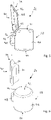
- the additional part 26 is in Figures 5 and 6 shown on its own, in a pre-assembly state (cf. figure 5 ) and in an assembled state (cf. figure 6 ).
- the additional part 26 comprises an intermediate section 38, which is embodied, for example, approximately cylindrically, and a web-shaped securing section 40.
- the intermediate section 38 extends between an upper bearing surface 42 in the installed position, which extends, for example, in a straight plane, and a lower bearing surface 44 in the installed position, cf. figures 1 and 8th .
- the intermediate section 38 has a cylindrical main body 46 protruding Anti-rotation section 48, which secures the intermediate section 38 against rotation within the receiving space 18, while allowing a displacement of the intermediate section 38 within the receiving space 18 parallel to an adjustment axis 50.
- the securing section 40 is web-shaped and extends in the preassembled state of the additional part 26 between a connection area 52 for connection to the intermediate section 38 and a free end 54 facing away therefrom, which is preferably provided with an insertion bevel 56 .
- the insertion bevel 56 serves to support the insertion of a front end 58 of the adjusting screw 30, cf. figure 8 .
- the securing section 40 is web-shaped and extends along an axis 60 which is inclined relative to the adjustment axis 50 when the additional part 26 is in a preassembled state, cf. figure 1 , and runs parallel to the adjustment axis 50 in an assembled state, cf. figure 8 .
- the additional part 26 is made in particular from a plastic material.
- the connection area 52 has a predetermined breaking point 62 which has a small, locally limited cross-section compared to the cross-section of the securing section 40 and compared to the cross-section of the main body 46 of the intermediate section 38 .
- the adjusting screw 30 has a screw head 64 with a tool engagement section 66 at its end remote from the front end 58 . This is followed in the direction of the front end 58 by a shaft 68 which carries the external thread 32 .
- the bearing bolt 14 of a frame of a window or a door or also a bearing bolt 14 of an assembly device is arranged with its front end 20 inside the receiving space 18 .
- a bottom 68, cf. figure 1 the fitting part 12 rests on a mounting surface 70 indicated schematically.
- the additional part 26 is introduced into the receiving space 18 from the upper end 24 .
- the additional part 26 then comes into contact (due to gravity) with its bearing surface 44 with the front end 20 of the bearing pin 14.
- the adjusting screw 30 is then inserted with the front end 58 forward from the upper end 24 into the receiving space 18, this insertion being supported by the inclined surface 56 of the securing section 40 and by the initially inclined position of the securing section 40 along the axis 60.
- the end of the external thread 32 adjacent to the front end 58 comes into engagement with an upper end of the internal thread 28 of the receiving space 18.
- the external thread 32 also comes into engagement with a surface 68 of the securing section 40 facing the receiving space 18, cf figures 1 and 5 . Due to this intervention, the (harder) external thread 32 of the adjusting screw deforms the (softer) securing section 40, so that a deformed section 70 (cf. figures 6 and 9 ) arises, which has an internal thread complementary to the external thread 32 and is in an anti-rotational engagement with the external thread 32 of the adjusting screw 30 .
- the adjusting screw 30 not only engages with its external thread 32 with the surface 68 of the securing section 40 (which is initially still connected to the intermediate section 38), but also with its end face during the course of screwing with the fitting part 12 End 58 in contact with the abutment surface 52 of the intermediate portion 38.
- the adjusting screw 30 can only be further screwed into the receiving space 18 when the intermediate portion 38 is released from the securing portion 40, which is made possible by the fact that the Predetermined breaking point 62, caused by the pressure of the adjusting screw 30, gives way and the securing section 40, starting from the inclined pre-assembly position (cf. figure 1 ) in a position parallel to the adjustment axis 50 (cf. figure 8 ) is transferred.
- the intermediate section 38 can move together with the adjustment screw 30 along the adjustment axis 50, so that a height of the Fitting part 12 can be adjusted relative to the front end 20 of the bearing pin 14.
- the securing section 40 is in continuous, anti-rotational engagement with the external thread 32 of the adjusting screw 30.
- the securing section is fixed in the groove 34 of the fitting part 12, viewed parallel to the adjustment axis 50.
- the adjustment screw 30 is arranged on the fitting part 12 in a non-rotating manner once the adjustment process is complete, so that an unwanted adjustment of the position of the adjustment screw 30 relative to the fitting part 12 and thus an unwanted adjustment of the Height of the wing is prevented.
- the main body 46 preferably has a material recess 72 below the connection area 52/the predetermined breaking point 62, which is dimensioned in such a way that the securing section 40 can also be attached to the upper end of the main body 46 of the Intermediate section 38 can be arranged past and adjacent to the anti-rotation section 48, compare e.g. 1 and 8th .
- the subassembly 10 is either fully assembled together with a wing on a frame-side bearing pin 14 or, in the event that the bearing pin 14 can be removed from an assembly device provided to be lifted from this bearing pin.
- the intermediate section 38 it is possible for the intermediate section 38 to be arranged in a loosely movable manner within the receiving space 18 between the stop 36 and the front end 58 of the adjusting screw 30 .
- this mobility is canceled again when the assembly 10 is mounted on a bearing pin 14 fixed to the frame; In the assembly position on a bearing bolt 14, the weight of a wing is supported via the fitting part 12, the adjusting screw 30 and the intermediate section 38 on the front end 20 of a bearing bolt 14.
Landscapes
- Engineering & Computer Science (AREA)
- Mechanical Engineering (AREA)
- Hinges (AREA)
Abstract
Description
- Die Erfindung betrifft eine Baugruppe zur Anordnung an einer Bandseite eines Flügels eines Fensters oder einer Tür, mit einem Beschlagteil zur Befestigung an dem Flügel, wobei das Beschlagteil einen Aufnahmeraum zur drehbaren Aufnahme zumindest des stirnseitigen Endes eines an einem Rahmen des Fensters oder der Tür anordenbaren oder angeordneten Lagerbolzens aufweist und wobei das Beschlagteil mit einer längs einer Einstellachse bewegbaren Einstellschraube zur Einstellung einer Lage des Beschlagteils relativ zu dem Lagerbolzen versehen ist.
- Baugruppen der vorgenannten Art sind auch unter der Bezeichnung "Ecklager" bekannt. Sie dienen dazu, den Flügel eines Fensters oder einer Tür um eine Drehachse relativ zu einem festen Rahmen verdrehen zu können. Um eine Höhenverstellung des Flügels relativ zu dem Rahmen zu ermöglichen, ist eine Einstellschraube vorgesehen, die mit dem Beschlagteil verschraubt ist und längs einer Einstellachse verschiedene Positionen einnehmen kann.
- Aus der
DE 10 2018 209 872 A1 ist eine Anordnung zur Lagerung eines Lagerbolzens mit einer Lagerhülse bekannt, in welcher der Lagerbolzen angeordnet wird, wobei ein stirnseitiges Ende der Einstellschraube auf einem stirnseitigen Ende des Lagerbolzens aufliegt. Um im Anschluss an eine Höheneinstellung eines Flügels eine unerwünschte Höhenverstellung zu verhindern, ist es eine Verdrehsicherung für die Einstellschraube vorgesehen, mit einem einstückig mit der Lagerhülse verbundenen Steg, der in einen Gewindeabschnitt der Einstellschraube hineinragt. - Ausgehend von der
DE 10 2018 209 872 A1 liegt der vorliegenden Erfindung die Aufgabe zugrunde, einen alternativen Aufbau für eine Baugruppe vorzuschlagen. - Diese Aufgabe wird bei einer Baugruppe der eingangs genannten Art gelöst durch ein Zusatzteil mit einem Zwischenabschnitt und einem Sicherungsabschnitt, wobei der Zwischenabschnitt zur Anordnung zwischen einem stirnseitigen Ende der Einstellschraube und dem stirnseitigen Ende des Lagerbolzens ausgebildet ist, wobei der Sicherungsabschnitt zum Eingriff in ein Außengewinde der Einstellschraube ausgebildet und an dem Beschlagteil verdrehgesichert ist, wobei in einem Vormontagezustand des Zusatzteils der Zwischenabschnitt und der Sicherungsabschnitt miteinander verbunden sind und wobei in einem Montagezustand des Zusatzteils der Zwischenabschnitt von dem Sicherungsabschnitt abgetrennt ist und gemeinsam mit der Einstellschraube entlang der Einstellachse bewegbar ist.
- Die erfindungsgemäße Baugruppe ermöglicht es, auf eine aus dem Stand der Technik bekannte Lagerhülse verzichten zu können. Die erfindungsgemäße Baugruppe ermöglicht eine einfache und schnelle Montage eines Flügels an einem Rahmen und eine einfache und schnelle Einstellung der Höhe des Flügels und ferner eine zuverlässige Sicherung gegen eine unerwünschte Verstellung der Höhe des Flügels.
- Zur Übertragung einer Gewichtskraft des Flügels auf den rahmenseitigen Lagerbolzen wird das Gewicht des Flügels über das Beschlagteil in die Einstellschraube und von dort in den Zwischenabschnitt eingeleitet. Das Gewicht der vorstehend genannten Bauteile stützt sich auf dem rahmenseitigen Lagerbolzen ab.
- In einem Vormontagezustand des Zusatzteils ist der Zwischenabschnitt mit einem Sicherungsabschnitt verbunden, sodass der Sicherungsabschnitt bei einer Montage der Baugruppe zunächst gemeinsam mit dem Zwischenabschnitt gehandhabt werden kann.
- In einem Montagezustand ist der Sicherungsabschnitt von dem Zwischenabschnitt abgetrennt und greift in ein Außengewinde der Einstellschraube ein und ist dabei gleichzeitig an dem Beschlagteil verdrehgesichert. Der Eingriff des Außengewindes der Einstellschraube in den Sicherungsabschnitt geht von einem Vormontagezustand des Zusatzteils ausgehend vorzugsweise damit einher, dass die Einstellschraube mit ihrem Außengewinde ein Innengewinde in einen Oberflächenabschnitt des Sicherungsabschnitts einschneidet oder einprägt.
- Der Sicherungsabschnitt bewirkt, dass die Einstellschraube zwar immer noch relativ zu dem Beschlagteil verdrehbar ist, zu diesem Zweck aber die verdrehhemmende Wirkung des Sicherungsabschnitts überwunden werden muss. Nach Abtrennung des Sicherungsabschnitts von dem Zwischenabschnitt ist die Einstellschraube gemeinsam mit dem Zwischenabschnitt relativ zu dem Beschlagteil entlang der Einstellachse bewegbar, und zwar unabhängig von dem (in diesem Zustand abgetrennten) Sicherungsabschnitt.
- Besonders bevorzugt ist es, wenn ein Übergang von dem Vormontagezustand in den Montagezustand damit einhergeht, dass das stirnseitige Ende der Einstellschraube beim Einschrauben der Einstellschraube in ein Innengewinde des Beschlagteils in Anlage mit einer Anlagefläche des Zwischenabschnitts gelangt und dass ein weiteres Einschrauben der Einstellschraube damit einhergeht, dass eine Druckkraft von dem stirnseitigen Ende der Einstellschraube auf die Anlagefläche ausgeübt wird, wodurch der Zwischenabschnitt von dem Sicherungsabschnitt abgetrennt wird. Die Einstellschraube wird mit ihrem Außengewinde also zunächst mit einem Innengewinde des Beschlagteils verschraubt, wobei das Außengewinde der Einstellschraube auch in Eingriff mit einer der Einstellschraube zugewandten Oberfläche des Sicherungsabschnitts gelangt.
- Im Zuge der Verschraubung gelangt das stirnseitige Ende der Einstellschraube in Anlage mit der Anlagefläche des Zwischenabschnitts. Wenn man für diesen Zustand gedanklich unterstellt, dass der Sicherungsabschnitt und der Zwischenabschnitt unlösbar miteinander verbunden wären, entspricht diese Situation dem Zustand des vollständigen Einschraubens einer Einstellschraube in ein Sackloch. Von diesem gedanklichen Zustand ausgehend kann nun aber der Zwischenabschnitt von dem Sicherungsabschnitt abgetrennt werden, indem das stirnseitige Ende der Einstellschraube durch weiteres Einschrauben der Einstellschraube in das Beschlagteil eine Druckkraft auf die Anlagefläche des Zwischenabschnitt ausübt und somit den Zwischenabschnitt von dem Sicherungsabschnitt trennt.
- Es ist besonders bevorzugt, wenn in dem Vormontagezustand des Zusatzteils der Zwischenabschnitt und der Sicherungsabschnitt miteinander stoffschlüssig verbunden sind. Dies ermöglicht die preisgünstige Bereitstellung eines einfach handhabbaren Zusatzteils.
- Es ist ferner bevorzugt, wenn ein Verbindungsbereich zwischen dem Zwischenabschnitt und dem Sicherungsabschnitt als Sollbruchstelle ausgebildet ist. Hierbei wird unter einer Sollbruchstelle ein Materialabschnitt verstanden, der kleiner ist als ein senkrecht zu der Einstellachse orientierter Querschnitt des Sicherungsabschnitts in einem zu der Sollbruchstelle benachbarten Bereich und als ein senkrecht zu der Einstellachse orientierter Querschnitt des Zwischenabschnitts in einem zu der Sollbruchstelle benachbarten Bereich.
- Bei einer besonders bevorzugten Ausführungsform ist das Zusatzteil aus einem Kunststoffmaterial hergestellt, insbesondere als Spritzgussteil. Dieses Material ist preisgünstig, wirkt verdrehhemmend und kann in einfacher Weise durch Einschrauben der Einstellschraube verformt werden.
- Vorzugsweise ist der Sicherungsabschnitt stegförmig ausgebildet und beansprucht somit nur wenig Bauraum, kann aber über eine Vielzahl von Gewindegängen mit dem Außengewinde der Einstellschraube in Eingriff stehen.
- Bevorzugt ist es ferner, wenn sich der Sicherungsabschnitt in der Montagelage parallel zu der Einstellachse erstreckt und/oder wenn der Sicherungsabschnitt in der Vormontagelage relativ zu der Einstellachse geneigt ist. Eine in der Montagelage parallele Anordnung zu der Einstellachse ermöglicht einen platzsparenden Aufbau und eine gleichmäßige Sicherungswirkung über mehrere Gewindegänge der Einstellschraube hinweg. Eine Neigung des Sicherungsabschnitts in der Vormontagelage ermöglicht die Ausbildung eines Trichters, in welchen hinein das stirnseitige Ende der Einstellschraube eingeführt werden kann. Dies vereinfacht die erstmalige Einprägung des Außengewindes der Einstellschraube in einen der Einstellschraube zugewandte Oberfläche des Sicherungs abschnitts.
- Ferner ist es bei einem zunächst geneigten Sicherungsabschnitt möglich, durch einen zu dem stirnseitigen Ende der Einstellschraube benachbarten Abschnitt des Außengewindes der Einstellschraube eine nach radial außen gerichtete Kraft auf einen zu dem Verbindungsbereich benachbarten Materialabschnitt des Sicherungsabschnitts auszuüben, sodass dieser Materialabschnitt des Sicherungsabschnitts nach radial außen gedrängt wird, wodurch eine Abtrennung des Sicherungsabschnitts von dem Zwischenabschnitt unterstützt wird.
- Es ist ferner bevorzugt, wenn zur Verdrehsicherung des Sicherungsabschnitts relativ zu dem Beschlagteil an dem Beschlagteil eine Nut vorgesehen ist, in welcher der Sicherungsabschnitt angeordnet ist. Diese Nut ist beispielsweise durch spanende Bearbeitung des Beschlagteils hergestellt. Die Nut erstreckt sich vorzugsweise parallel zu der Einstellachse.
- Es ist ferner möglich, dass der Zwischenabschnitt einen Verdrehsicherungsabschnitt aufweist, der mit dem Beschlagteil zusammenwirkt. Dies hat den Vorteil, dass während einer Nutzung des Flügels und dessen Drehung relativ zu einem Rahmen der Zwischenabschnitt in Drehrichtung relativ zu dem Flügel fixiert ist, sodass eine Reibbewegung zwischen dem stirnseitigen Ende der Einstellschraube und der Anlagefläche des Zwischenabschnitts verhindert wird. Auf diese Weise ist sichergestellt, dass bei einer Drehverlagerung des Flügels relativ zu dem Rahmen eine Reibbewegung ausschließlich zwischen Oberflächen des Zwischenabschnitts und des Lagerbolzens stattfindet.
- Vorzugsweise ist der Verdrehsicherungsabschnitt des Zwischenabschnitts ebenfalls in der Nut gelagert, die auch zur Anordnung des Sicherungsabschnitts dient. Dies bedeutet, dass die Nut über ihre gesamte Erstreckung und insbesondere sowohl auf Höhe des Sicherungsabschnitts als auch auf Höhe des Verdrehsicherungsabschnitts des Zwischenabschnitts denselben Querschnitt aufweisen kann.
- Es ist ferner bevorzugt, wenn das Zusatzteil eine Auflagefläche zur Auflage auf dem stirnseitigen Ende des Lagerbolzens aufweist und wenn die Auflagefläche eine konkave Krümmung aufweist. Dies ermöglicht die Bereitstellung einer Zentrierwirkung des Zwischenabschnitts relativ zu dem Lagerbolzen und ferner einen reibungsoptimierten Kontakt zwischen dem Lagerbolzen und der Auflagefläche.
- Der Lagerbolzen weist an seinem stirnseitigen Ende vorzugsweise ebenfalls eine gekrümmte Oberfläche auf, die zu der Krümmung der Auflagefläche komplementär, also insbesondere konvex, gekrümmt ist. Der Krümmungsradius der Oberfläche des Lagerbolzens kann zu dem Krümmungsradius der Krümmung der Auflagefläche identisch sein oder geringfügig kleiner.
- Weitere Merkmale und Vorteile der Erfindung sind Gegenstand der nachfolgenden Beschreibung und der zeichnerischen Darstellung eines bevorzugten Ausführungsbeispiels.
- In der Zeichnung zeigt:
- Fig. 1
- einen Vertikalschnitt einer Ausführungsform einer Baugruppe (noch ohne Einstellschraube), wobei ein Zusatzteil einen Vormontagezustand einnimmt;
- Fig. 2
- eine Draufsicht der Baugruppe gemäß
Fig. 1 ; - Fig. 3
- eine Schnittdarstellung längs einer in
Fig. 1 mit III - III bezeichneten Schnittebene; - Fig. 4
- eine Schnittdarstellung längs einer in
Fig. 1 mit IV - IV bezeichneten Schnittebene; - Fig. 5
- eine perspektivische Darstellung des Zusatzteils gemäß
Fig. 1 ; - Fig. 6
- eine der
Fig. 5 entsprechende Darstellung, wobei das Zusatzteil einen Montagezustand einnimmt; - Fig. 7
- eine der
Fig. 6 entsprechende Darstellung, mit einer Einstellschraube; - Fig. 8
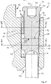
- einen Vertikalschnitt der Baugruppe (mit Einstellschraube), wobei das Zusatzteil den Montagezustand einnimmt;
- Fig. 9
- eine Schnittdarstellung längs einer in
Fig. 8 mit IX - IX bezeichneten Schnittebene; und - Fig. 10
- eine Schnittdarstellung längs einer in
Fig. 8 mit X - X bezeichneten Schnittebene. - In der Zeichnung ist eine Ausführungsform einer Baugruppe 10 insgesamt mit den Bezugszeichen 10 bezeichnet. Die Baugruppe 10 umfasst ein Beschlagteil 12, das mit einem an sich bekannten und daher nicht dargestellten Abschnitt mit einem Flügel eines Fensters oder einer Tür verbunden ist oder verbunden wird.
- Die Baugruppe 10 dient dazu, den Flügel gemeinsam mit dem Beschlagteil 12 um einen Lagerbolzen 14 verdrehen zu können, der an einem Rahmen des Fensters oder der Tür angeordnet ist. Bei dem Lagerbolzen 14 kann es sich um ein lagefestes Bauteil handeln (für einen nur drehbaren Flügel) oder aber um ein Bauteil, welches seinerseits verkippt werden kann, sodass der Flügel nicht nur um den Lagerbolzen 14 herum verdreht werden kann, sondern gemeinsam mit dem Lagerbolzen 14 auch in eine Kippstellung gebracht werden kann.
- Das Beschlagteil 12 umfasst einen näherungsweise hohlzylindrischen Aufnahmeabschnitt 16, der einen Aufnahmeraum 18 umfangsseitig begrenzt, welcher unter anderem zur drehbaren Aufnahme zumindest eines stirnseitigen Endes 20 des Lagerbolzens 14 dient.
- Der Aufnahmeraum 18 ist an einem in Einbaulage der Baugruppe 10 unteren Ende 22 offen, zwecks Durchtritt oder Eintritt des Lagerbolzens 14. Der Aufnahmeraum 18 ist an einem in Einbaulage der Baugruppe 10 oberen Ende 24 ebenfalls offen, wodurch ermöglicht wird, dass ein Zusatzteil 26 von dem oberen Ende 24 her in den Aufnahmeraum 18 eingeführt wird.
- Der Aufnahmeraum 18 weist entlang seiner Erstreckung zwischen dem unteren Ende 22 und dem oberen Ende 24 zumindest entlang einer Teilstrecke ein Innengewinde 28 auf, das zur Verschraubung mit einer Einstellschraube 30 dient, das ein Außengewinde 32 aufweist.
- An der umfangsseitigen Begrenzung des Aufnahmeraums 18 ist ferner eine Nut 34 vorgesehen, welche den ansonsten zylindrischen Aufnahmeraum 18 im Bereich der Nut 34 erweitert. Die Nut 34 erstreckt sich von dem oberen Ende 24 des Aufnahmeraums 18 bis zu einem Absatz 36, der oberhalb des unteren Endes 22 vorgesehen ist.
- Das Zusatzteil 26 ist in
Figuren 5 und 6 in Alleinstellung dargestellt, und zwar in einem Vormontagezustand (vgl.Figur 5 ) und in einem Montagezustand (vgl.Figur 6 ). - Das Zusatzteil 26 umfasst einen Zwischenabschnitt 38, der bspw. annähernd zylindrisch ausgebildet ist, und einen stegförmigen Sicherungsabschnitt 40.
- Der Zwischenabschnitt 38 erstreckt sich zwischen einer in Einbaulage oberen Anlagefläche 42, die sich beispielsweise in einer geraden Ebene erstreckt, und einer in Einbaulage unteren Auflagefläche 44, vgl.
Figuren 1 und8 . - Der Zwischenabschnitt 38 weist einen von einem zylindrischen Hauptkörper 46 abragenden Verdrehsicherungsabschnitt 48 auf, welcher den Zwischenabschnitt 38 gegen eine Verdrehung innerhalb des Aufnahmeraums 18 sichert, dabei aber eine Verlagerung des Zwischenabschnitts 38 innerhalb des Aufnahmeraums 18 parallel zu einer Einstellachse 50 zulässt.
- Der Sicherungsabschnitt 40 ist stegförmig und erstreckt sich in dem Vormontagezustand des Zusatzteils 26 zwischen einem Verbindungsbereich 52 zur Verbindung mit dem Zwischenabschnitt 38 und einem davon abgewandten freien Ende 54, das vorzugsweise mit einer Einführschräge 56 versehen ist. Die Einführschräge 56 dient zur Unterstützung der Einführung eines stirnseitigen Endes 58 der Einstellschraube 30, vgl.
Figur 8 . - Der Sicherungsabschnitt 40 ist stegförmig und erstreckt sich entlang einer Achse 60, welche in einem Vormontagezustand des Zusatzteils 26 relativ zu der Einstellachse 50 geneigt ist, vgl.
Figur 1 , und in einem Montagezustand zu der Einstellachse 50 parallel verläuft, vgl.Figur 8 . - Das Zusatzteil 26 ist insbesondere aus einem Kunststoffmaterial hergestellt. Der Verbindungsbereich 52 weist eine Sollbruchstelle 62 auf, welche einen im Vergleich zu dem Querschnitt des Sicherungsabschnitts 40 und im Vergleich zu dem Querschnitt des Hauptkörpers 46 des Zwischenabschnitts 38 kleinen, lokal begrenzten Querschnitt aufweist.
- Die Einstellschraube 30 weist an ihrem dem stirnseitigen Ende 58 abgewandten Ende einen Schraubenkopf 64 mit einem Werkzeugeingriffsabschnitt 66 auf. An diesen schließt sich in Richtung auf das stirnseitige Ende 58 ein Schaft 68 an, der das Außengewinde 32 trägt.
- Zur Montage der Baugruppe 10 wird der Lagerbolzen 14 eines Rahmens eines Fensters oder einer Tür oder auch ein Lagerbolzen 14 einer Montagevorrichtung mit seinem stirnseitigen Ende 20 innerhalb des Aufnahmeraums 18 angeordnet. Hierbei ist es möglich, dass eine Unterseite 68, vgl.
Figur 1 , des Beschlagteils 12 auf einer schematisch angedeuteten Montagefläche 70 aufliegt. - Danach wird das Zusatzteil 26 von dem oberen Ende 24 her in den Aufnahmeraum 18 eingeführt. Das Zusatzteil 26 gelangt dann (schwerkraftbedingt) mit seiner Auflagefläche 44 in Kontakt mit dem stirnseitigen Ende 20 des Lagerbolzens 14.
- Anschließend wird die Einstellschraube 30 mit dem stirnseitigen Ende 58 voran von dem oberen Ende 24 her in den Aufnahmeraum 18 eingeführt, wobei diese Einführung durch die geneigte Fläche 56 des Sicherungsabschnitts 40 und durch die entlang der Achse 60 zunächst geneigte Lage des Sicherungsabschnitts 40 unterstützt wird.
- Das zu dem stirnseitigen Ende 58 benachbarte Ende des Außengewindes 32 gelangt in Eingriff mit einem oberen Ende des Innengewindes 28 des Aufnahmeraums 18. Beginnend von diesem Eingriff an oder entlang der Einstellachse 50 gesehen auch bereits vorher oder diesem Eingriff folgend gelangt das Außengewinde 32 zusätzlich in Eingriff mit einer dem Aufnahmeraum 18 zugewandten Oberfläche 68 des Sicherungsabschnitts 40, vergleiche
Figuren 1 und5 . Durch diesen Eingriff bedingt verformt das (härtere) Außengewinde 32 der Einstellschraube den (weicheren) Sicherungsabschnitt 40, sodass ein verformter Abschnitt 70 (vgl.Figuren 6 und9 ) entsteht, der ein zu dem Außengewinde 32 komplementäres Innengewinde aufweist und in einem drehhemmenden Eingriff mit dem Außengewinde 32 der Einstellschraube 30 steht. - Um diesen Montagezustand zu erreichen, gelangt die Einstellschraube 30 im Zuge der Verschraubung mit dem Beschlagteil 12 nicht nur mit seinem Außengewinde 32 in Eingriff mit der Oberfläche 68 des Sicherungsabschnitts 40 (der zunächst noch mit dem Zwischenabschnitt 38 verbunden ist), sondern auch mit ihrem stirnseitigen Ende 58 in Kontakt mit der Anlagefläche 52 des Zwischenabschnitts 38. Wenn dieser Zustand erreicht ist, kann die Einstellschraube 30 nur noch weiter in den Aufnahmeraum 18 eingeschraubt werden, wenn sich der Zwischenabschnitt 38 von dem Sicherungsabschnitt 40 löst, was dadurch ermöglicht wird, dass die Sollbruchstelle 62, bedingt durch den Druck der Einstellschraube 30, nachgibt und der Sicherungsabschnitt 40 ausgehend von der geneigten Vormontagelage (vgl.
Figur 1 ) in eine zu der Einstellachse 50 parallele Lage (vgl.Figur 8 ) überführt wird. - Nach der Trennung des Zwischenabschnitts 38 von dem Sicherungsabschnitt 40 kann sich der Zwischenabschnitt 38 gemeinsam mit der Einstellschraube 30 längs der Einstellachse 50 bewegen, sodass eine Höhe des Beschlagteils 12 relativ zu dem stirnseitigen Ende 20 des Lagerbolzens 14 eingestellt werden kann. Während dieser Einstellung und auch danach befindet sich der Sicherungsabschnitt 40 in einem fortwährenden, drehhemmenden Eingriff mit dem Außengewinde 32 der Einstellschraube 30. Dabei ist der Sicherungsabschnitt parallel zu der Einstellachse 50 gesehen in der Nut 34 des Beschlagteils 12 fixiert.
- Während eines Höhen-Einstellvorgangs muss zwar ein erhöhtes Drehmoment aufgewendet werden, aber dafür ist die Einstellschraube 30 nach Abschluss des Einstellvorgangs an dem Beschlagteil 12 verdrehgesichert angeordnet, sodass eine unerwünschte Verstellung der Position der Einstellschraube 30 relativ zu dem Beschlagteil 12 und somit eine unerwünschte Verstellung der Höhe des Flügels verhindert wird.
- Um den Höhen-Einstellvorgang über einen besonders großen Verstellweg ausführen zu können, weist der Hauptkörper 46 unterhalb des Verbindungsbereichs 52 / der Sollbruchstelle 62 vorzugsweise eine Materialausnehmung 72 auf, die so bemessen ist, dass der Sicherungsabschnitt 40 auch an dem oberen Ende des Hauptkörpers 46 des Zwischenabschnitts 38 vorbei und benachbart zu dem Verdrehsicherungsabschnitt 48 angeordnet werden kann, vergleiche bspw.
Fig. 1 und8 . - Nach Abschluss des Einstellvorgangs ist die Baugruppe 10 entweder gemeinsam mit einem Flügel an einem rahmenseitigen Lagerbolzen 14 fertig montiert oder kann, für den Fall, dass der Lagerbolzen 14 von einer Montageeinrichtung bereitgestellt, von diesem Lagerbolzen abgehoben werden. Für diesen Fall ist es möglich, dass der Zwischenabschnitt 38 innerhalb des Aufnahmeraums 18 zwischen dem Anschlag 36 und dem stirnseitigen Ende 58 der Einstellschraube 30 lose bewegbar angeordnet ist. Diese Bewegbarkeit wird aber bei der Montage der Baugruppe 10 an einen rahmenfesten Lagerbolzen 14 wieder aufgehoben; in der Montagelage an einem Lagerbolzen 14 wird die Gewichtskraft eines Flügels über das Beschlagteil 12, die Einstellschraube 30 und den Zwischenabschnitt 38 auf dem stirnseitigen Ende 20 eines Lagerbolzens 14 abgestützt.
Claims (11)
- Baugruppe (10) zur Anordnung an einer Bandseite eines Flügels eines Fensters oder einer Tür, mit einem Beschlagteil (12) zur Befestigung an dem Flügel, wobei das Beschlagteil einen Aufnahmeraum (18) zur drehbaren Aufnahme zumindest des stirnseitigen Endes (20) eines an einem Rahmen des Fensters oder der Tür anordenbaren oder angeordneten Lagerbolzens (14) aufweist und wobei das Beschlagteil (12) mit einer längs einer Einstellachse (50) bewegbaren Einstellschraube (30) zur Einstellung einer Lage des Beschlagteils (12) relativ zu dem Lagerbolzen (14) versehen ist, gekennzeichnet durch ein Zusatzteil (26) mit einem Zwischenabschnitt (38) und einem Sicherungsabschnitt (40), wobei der Zwischenabschnitt (38) zur Anordnung zwischen einem stirnseitigen Ende (58) der Einstellschraube (30) und dem stirnseitigen Ende (20) des Lagerbolzens (14) ausgebildet ist, wobei der Sicherungsabschnitt (40) zum Eingriff in ein Außengewinde (32) der Einstellschraube (30) ausgebildet und an dem Beschlagteil (12) verdrehgesichert ist, wobei in einem Vormontagezustand des Zusatzteils (26) der Zwischenabschnitt (38) und der Sicherungsabschnitt (40) miteinander verbunden sind und wobei in einem Montagezustand des Zusatzteils (26) der Zwischenabschnitt (38) von dem Sicherungsabschnitt (40) abgetrennt ist und gemeinsam mit der Einstellschraube (30) entlang der Einstellachse (50) bewegbar ist.
- Baugruppe (10) nach Anspruch 1, dadurch gekennzeichnet, dass ein Übergang von dem Vormontagezustand in den Montagezustand damit einhergeht, dass das stirnseitige Ende (58) der Einstellschraube (30) beim Einschrauben der Einstellschraube (30) in ein Innengewinde (28) des Beschlagteils (12) in Anlage mit einer Anlagefläche (42) des Zwischenabschnitts (38) gelangt und dass ein weiteres Einschrauben der Einstellschraube (30) damit einhergeht, dass eine Druckkraft von dem stirnseitigen Ende (58) der Einstellschraube (30) auf die Anlagefläche (42) ausgeübt wird, wodurch der Zwischenabschnitt (38) von dem Sicherungsabschnitt (40) abgetrennt wird.
- Baugruppe (10) nach einem der vorstehenden Ansprüche, dadurch gekennzeichnet, dass in dem Vormontagezustand des Zusatzteils (26) der Zwischenabschnitt (38) und der Sicherungsabschnitt (40) miteinander stoffschlüssig verbunden sind.
- Baugruppe (10) nach einem der vorstehenden Ansprüche, dadurch gekennzeichnet, dass ein Verbindungsbereich (52) zwischen dem Zwischenabschnitt (38) und dem Sicherungsabschnitt (40) als Sollbruchstelle (62) ausgebildet ist.
- Baugruppe (10) nach einem der vorstehenden Ansprüche, dadurch gekennzeichnet, dass das Zusatzteil (26) aus einem Kunststoffmaterial hergestellt ist.
- Baugruppe (10) nach einem der vorstehenden Ansprüche, dadurch gekennzeichnet, dass der Sicherungsabschnitt (40) stegförmig ausgebildet ist.
- Baugruppe (10) nach einem der vorstehenden Ansprüche, dadurch gekennzeichnet, dass sich der Sicherungsabschnitt (40) in der Montagelage parallel zu der Einstellachse (50) erstreckt und/oder dass der Sicherungsabschnitt (40) in der Vormontagelage relativ zu der Einstellachse (50) geneigt ist.
- Baugruppe (10) nach einem der vorstehenden Ansprüche, dadurch gekennzeichnet, dass zur Verdrehsicherung des Sicherungsabschnitts (40) relativ zu dem Beschlagteil (12) an dem Beschlagteil (12) eine Nut (34) vorgesehen ist, in welcher der Sicherungsabschnitt (40) angeordnet ist.
- Baugruppe (10) nach einem der vorstehenden Ansprüche, dadurch gekennzeichnet, dass der Zwischenabschnitt (38) einen Verdrehsicherungsabschnitt (43) aufweist, der mit dem Beschlagteil (12) zusammenwirkt.
- Baugruppe (10) nach Anspruch 9 bei Rückbezug auf Anspruch 8, dadurch gekennzeichnet, dass der Verdrehsicherungsabschnitt (48) ebenfalls in der Nut (40) angeordnet ist.
- Baugruppe (10) nach einem der vorstehenden Ansprüche, dadurch gekennzeichnet, dass der Zwischenabschnitt (38) eine Auflagefläche (44) zur Auflage auf dem stirnseitigen Ende (20) des Lagerbolzens (14) aufweist und dass die Auflagefläche (44) eine konkave Krümmung aufweist.
Priority Applications (1)
| Application Number | Priority Date | Filing Date | Title |
|---|---|---|---|
| EP21177455.9A EP4098832B1 (de) | 2021-06-02 | 2021-06-02 | Baugruppe zur anordnung an einer bandseite eines flügels eines fensters oder einer tür |
Applications Claiming Priority (1)
| Application Number | Priority Date | Filing Date | Title |
|---|---|---|---|
| EP21177455.9A EP4098832B1 (de) | 2021-06-02 | 2021-06-02 | Baugruppe zur anordnung an einer bandseite eines flügels eines fensters oder einer tür |
Publications (2)
| Publication Number | Publication Date |
|---|---|
| EP4098832A1 true EP4098832A1 (de) | 2022-12-07 |
| EP4098832B1 EP4098832B1 (de) | 2023-05-17 |
Family
ID=76250239
Family Applications (1)
| Application Number | Title | Priority Date | Filing Date |
|---|---|---|---|
| EP21177455.9A Active EP4098832B1 (de) | 2021-06-02 | 2021-06-02 | Baugruppe zur anordnung an einer bandseite eines flügels eines fensters oder einer tür |
Country Status (1)
| Country | Link |
|---|---|
| EP (1) | EP4098832B1 (de) |
Citations (4)
| Publication number | Priority date | Publication date | Assignee | Title |
|---|---|---|---|---|
| EP0940540A2 (de) * | 1998-03-05 | 1999-09-08 | Dr. Hahn GmbH & Co. KG | Band für Türen, Fenster oder dergleichen |
| EP1820927A2 (de) * | 2006-02-18 | 2007-08-22 | GLUSKE-BKV GmbH | Buchsenmodul |
| EP2666943A1 (de) * | 2012-05-23 | 2013-11-27 | Roto Frank Ag | Lagereinsatz für ein Lager eines Fensters, einer Tür oder dergleichen |
| DE102018209872A1 (de) | 2018-06-19 | 2019-12-19 | Aug. Winkhaus Gmbh & Co. Kg | Lagerung für einen Flügel an einem Rahmen |
-
2021
- 2021-06-02 EP EP21177455.9A patent/EP4098832B1/de active Active
Patent Citations (4)
| Publication number | Priority date | Publication date | Assignee | Title |
|---|---|---|---|---|
| EP0940540A2 (de) * | 1998-03-05 | 1999-09-08 | Dr. Hahn GmbH & Co. KG | Band für Türen, Fenster oder dergleichen |
| EP1820927A2 (de) * | 2006-02-18 | 2007-08-22 | GLUSKE-BKV GmbH | Buchsenmodul |
| EP2666943A1 (de) * | 2012-05-23 | 2013-11-27 | Roto Frank Ag | Lagereinsatz für ein Lager eines Fensters, einer Tür oder dergleichen |
| DE102018209872A1 (de) | 2018-06-19 | 2019-12-19 | Aug. Winkhaus Gmbh & Co. Kg | Lagerung für einen Flügel an einem Rahmen |
Also Published As
| Publication number | Publication date |
|---|---|
| EP4098832B1 (de) | 2023-05-17 |
Similar Documents
| Publication | Publication Date | Title |
|---|---|---|
| EP2318723B1 (de) | Befestigungsanordnung mit toleranzausgleich | |
| EP2130722B1 (de) | Toleranzausgleichselement | |
| DE68905354T2 (de) | Einstellbarer anschlag. | |
| EP3036443B1 (de) | Verfahren zum verbinden von bauteilen sowie baugruppe | |
| EP1626185A1 (de) | Einstelleinheit zum Einstellen des Abstandes zwischen zwei Bauteilen | |
| EP2532568A2 (de) | Vorrichtung zur Befestigung eines Anbauteils, zum Beispiel einer Reling, an einer Fahrzeugkarosserie | |
| EP4737748A1 (de) | Verbindungselement und verbindungsanordnung | |
| DE69503024T2 (de) | Knopfartige Schliesseinrichtung | |
| DE19832117A1 (de) | Halterung für eine spannungsfreie Lagerung einer Glasscheibe | |
| DE4011909C2 (de) | ||
| EP1600588B1 (de) | Türband | |
| DE102019206750B4 (de) | Vorrichtung zum Ausgleichen von Toleranzen zwischen einem ersten Bauteil und einem zweiten Bauteil | |
| DE3835543C1 (en) | Fastening element | |
| EP3807012B1 (de) | Zentrifuge | |
| DE102009025121B4 (de) | System zum Befestigen eines Panels | |
| EP4098832B1 (de) | Baugruppe zur anordnung an einer bandseite eines flügels eines fensters oder einer tür | |
| DE102008040659B3 (de) | Türband sowie Tür | |
| EP0215281A2 (de) | Flügellager für ein Fenster, eine Tür od. dgl. | |
| DE3137112A1 (de) | Aushaengbares tuerscharnier | |
| DE8804008U1 (de) | Scharnier | |
| EP0891573A1 (de) | Brillenfassung mit einer gegen lösen gesicherten schliessblock-schraubenverbindung | |
| DE202004004407U1 (de) | Zug-Druck-Stange | |
| DE102016118047B4 (de) | Hygienischer Höhenausgleichsfuß | |
| EP0729540B1 (de) | Tür- oder fensterband | |
| EP3574813B1 (de) | Scharnier für eine toilettensitzgarnitur |
Legal Events
| Date | Code | Title | Description |
|---|---|---|---|
| PUAI | Public reference made under article 153(3) epc to a published international application that has entered the european phase |
Free format text: ORIGINAL CODE: 0009012 |
|
| STAA | Information on the status of an ep patent application or granted ep patent |
Free format text: STATUS: REQUEST FOR EXAMINATION WAS MADE |
|
| 17P | Request for examination filed |
Effective date: 20220321 |
|
| AK | Designated contracting states |
Kind code of ref document: A1 Designated state(s): AL AT BE BG CH CY CZ DE DK EE ES FI FR GB GR HR HU IE IS IT LI LT LU LV MC MK MT NL NO PL PT RO RS SE SI SK SM TR |
|
| GRAP | Despatch of communication of intention to grant a patent |
Free format text: ORIGINAL CODE: EPIDOSNIGR1 |
|
| STAA | Information on the status of an ep patent application or granted ep patent |
Free format text: STATUS: GRANT OF PATENT IS INTENDED |
|
| INTG | Intention to grant announced |
Effective date: 20230110 |
|
| GRAS | Grant fee paid |
Free format text: ORIGINAL CODE: EPIDOSNIGR3 |
|
| GRAA | (expected) grant |
Free format text: ORIGINAL CODE: 0009210 |
|
| STAA | Information on the status of an ep patent application or granted ep patent |
Free format text: STATUS: THE PATENT HAS BEEN GRANTED |
|
| AK | Designated contracting states |
Kind code of ref document: B1 Designated state(s): AL AT BE BG CH CY CZ DE DK EE ES FI FR GB GR HR HU IE IS IT LI LT LU LV MC MK MT NL NO PL PT RO RS SE SI SK SM TR |
|
| REG | Reference to a national code |
Ref country code: GB Ref legal event code: FG4D Free format text: NOT ENGLISH |
|
| REG | Reference to a national code |
Ref country code: CH Ref legal event code: EP |
|
| REG | Reference to a national code |
Ref country code: DE Ref legal event code: R096 Ref document number: 502021000687 Country of ref document: DE |
|
| REG | Reference to a national code |
Ref country code: IE Ref legal event code: FG4D Free format text: LANGUAGE OF EP DOCUMENT: GERMAN |
|
| P01 | Opt-out of the competence of the unified patent court (upc) registered |
Effective date: 20230505 |
|
| REG | Reference to a national code |
Ref country code: AT Ref legal event code: REF Ref document number: 1568419 Country of ref document: AT Kind code of ref document: T Effective date: 20230615 |
|
| REG | Reference to a national code |
Ref country code: NL Ref legal event code: FP |
|
| REG | Reference to a national code |
Ref country code: LT Ref legal event code: MG9D |
|
| PG25 | Lapsed in a contracting state [announced via postgrant information from national office to epo] |
Ref country code: SE Free format text: LAPSE BECAUSE OF FAILURE TO SUBMIT A TRANSLATION OF THE DESCRIPTION OR TO PAY THE FEE WITHIN THE PRESCRIBED TIME-LIMIT Effective date: 20230517 Ref country code: PT Free format text: LAPSE BECAUSE OF FAILURE TO SUBMIT A TRANSLATION OF THE DESCRIPTION OR TO PAY THE FEE WITHIN THE PRESCRIBED TIME-LIMIT Effective date: 20230918 Ref country code: NO Free format text: LAPSE BECAUSE OF FAILURE TO SUBMIT A TRANSLATION OF THE DESCRIPTION OR TO PAY THE FEE WITHIN THE PRESCRIBED TIME-LIMIT Effective date: 20230817 Ref country code: ES Free format text: LAPSE BECAUSE OF FAILURE TO SUBMIT A TRANSLATION OF THE DESCRIPTION OR TO PAY THE FEE WITHIN THE PRESCRIBED TIME-LIMIT Effective date: 20230517 |
|
| PG25 | Lapsed in a contracting state [announced via postgrant information from national office to epo] |
Ref country code: RS Free format text: LAPSE BECAUSE OF FAILURE TO SUBMIT A TRANSLATION OF THE DESCRIPTION OR TO PAY THE FEE WITHIN THE PRESCRIBED TIME-LIMIT Effective date: 20230517 Ref country code: PL Free format text: LAPSE BECAUSE OF FAILURE TO SUBMIT A TRANSLATION OF THE DESCRIPTION OR TO PAY THE FEE WITHIN THE PRESCRIBED TIME-LIMIT Effective date: 20230517 Ref country code: LV Free format text: LAPSE BECAUSE OF FAILURE TO SUBMIT A TRANSLATION OF THE DESCRIPTION OR TO PAY THE FEE WITHIN THE PRESCRIBED TIME-LIMIT Effective date: 20230517 Ref country code: LT Free format text: LAPSE BECAUSE OF FAILURE TO SUBMIT A TRANSLATION OF THE DESCRIPTION OR TO PAY THE FEE WITHIN THE PRESCRIBED TIME-LIMIT Effective date: 20230517 Ref country code: IS Free format text: LAPSE BECAUSE OF FAILURE TO SUBMIT A TRANSLATION OF THE DESCRIPTION OR TO PAY THE FEE WITHIN THE PRESCRIBED TIME-LIMIT Effective date: 20230917 Ref country code: HR Free format text: LAPSE BECAUSE OF FAILURE TO SUBMIT A TRANSLATION OF THE DESCRIPTION OR TO PAY THE FEE WITHIN THE PRESCRIBED TIME-LIMIT Effective date: 20230517 Ref country code: GR Free format text: LAPSE BECAUSE OF FAILURE TO SUBMIT A TRANSLATION OF THE DESCRIPTION OR TO PAY THE FEE WITHIN THE PRESCRIBED TIME-LIMIT Effective date: 20230818 |
|
| PG25 | Lapsed in a contracting state [announced via postgrant information from national office to epo] |
Ref country code: FI Free format text: LAPSE BECAUSE OF FAILURE TO SUBMIT A TRANSLATION OF THE DESCRIPTION OR TO PAY THE FEE WITHIN THE PRESCRIBED TIME-LIMIT Effective date: 20230517 |
|
| PG25 | Lapsed in a contracting state [announced via postgrant information from national office to epo] |
Ref country code: SK Free format text: LAPSE BECAUSE OF FAILURE TO SUBMIT A TRANSLATION OF THE DESCRIPTION OR TO PAY THE FEE WITHIN THE PRESCRIBED TIME-LIMIT Effective date: 20230517 |
|
| PG25 | Lapsed in a contracting state [announced via postgrant information from national office to epo] |
Ref country code: SM Free format text: LAPSE BECAUSE OF FAILURE TO SUBMIT A TRANSLATION OF THE DESCRIPTION OR TO PAY THE FEE WITHIN THE PRESCRIBED TIME-LIMIT Effective date: 20230517 Ref country code: SK Free format text: LAPSE BECAUSE OF FAILURE TO SUBMIT A TRANSLATION OF THE DESCRIPTION OR TO PAY THE FEE WITHIN THE PRESCRIBED TIME-LIMIT Effective date: 20230517 Ref country code: RO Free format text: LAPSE BECAUSE OF FAILURE TO SUBMIT A TRANSLATION OF THE DESCRIPTION OR TO PAY THE FEE WITHIN THE PRESCRIBED TIME-LIMIT Effective date: 20230517 Ref country code: EE Free format text: LAPSE BECAUSE OF FAILURE TO SUBMIT A TRANSLATION OF THE DESCRIPTION OR TO PAY THE FEE WITHIN THE PRESCRIBED TIME-LIMIT Effective date: 20230517 Ref country code: DK Free format text: LAPSE BECAUSE OF FAILURE TO SUBMIT A TRANSLATION OF THE DESCRIPTION OR TO PAY THE FEE WITHIN THE PRESCRIBED TIME-LIMIT Effective date: 20230517 Ref country code: CZ Free format text: LAPSE BECAUSE OF FAILURE TO SUBMIT A TRANSLATION OF THE DESCRIPTION OR TO PAY THE FEE WITHIN THE PRESCRIBED TIME-LIMIT Effective date: 20230517 |
|
| REG | Reference to a national code |
Ref country code: DE Ref legal event code: R097 Ref document number: 502021000687 Country of ref document: DE |
|
| PG25 | Lapsed in a contracting state [announced via postgrant information from national office to epo] |
Ref country code: MC Free format text: LAPSE BECAUSE OF FAILURE TO SUBMIT A TRANSLATION OF THE DESCRIPTION OR TO PAY THE FEE WITHIN THE PRESCRIBED TIME-LIMIT Effective date: 20230517 |
|
| PG25 | Lapsed in a contracting state [announced via postgrant information from national office to epo] |
Ref country code: MC Free format text: LAPSE BECAUSE OF FAILURE TO SUBMIT A TRANSLATION OF THE DESCRIPTION OR TO PAY THE FEE WITHIN THE PRESCRIBED TIME-LIMIT Effective date: 20230517 |
|
| PG25 | Lapsed in a contracting state [announced via postgrant information from national office to epo] |
Ref country code: LU Free format text: LAPSE BECAUSE OF NON-PAYMENT OF DUE FEES Effective date: 20230602 |
|
| PLBE | No opposition filed within time limit |
Free format text: ORIGINAL CODE: 0009261 |
|
| STAA | Information on the status of an ep patent application or granted ep patent |
Free format text: STATUS: NO OPPOSITION FILED WITHIN TIME LIMIT |
|
| REG | Reference to a national code |
Ref country code: IE Ref legal event code: MM4A |
|
| PG25 | Lapsed in a contracting state [announced via postgrant information from national office to epo] |
Ref country code: LU Free format text: LAPSE BECAUSE OF NON-PAYMENT OF DUE FEES Effective date: 20230602 |
|
| PG25 | Lapsed in a contracting state [announced via postgrant information from national office to epo] |
Ref country code: IE Free format text: LAPSE BECAUSE OF NON-PAYMENT OF DUE FEES Effective date: 20230602 |
|
| REG | Reference to a national code |
Ref country code: DE Ref legal event code: R082 Ref document number: 502021000687 Country of ref document: DE |
|
| 26N | No opposition filed |
Effective date: 20240220 |
|
| PG25 | Lapsed in a contracting state [announced via postgrant information from national office to epo] |
Ref country code: IE Free format text: LAPSE BECAUSE OF NON-PAYMENT OF DUE FEES Effective date: 20230602 |
|
| PG25 | Lapsed in a contracting state [announced via postgrant information from national office to epo] |
Ref country code: SI Free format text: LAPSE BECAUSE OF FAILURE TO SUBMIT A TRANSLATION OF THE DESCRIPTION OR TO PAY THE FEE WITHIN THE PRESCRIBED TIME-LIMIT Effective date: 20230517 |
|
| PG25 | Lapsed in a contracting state [announced via postgrant information from national office to epo] |
Ref country code: SI Free format text: LAPSE BECAUSE OF FAILURE TO SUBMIT A TRANSLATION OF THE DESCRIPTION OR TO PAY THE FEE WITHIN THE PRESCRIBED TIME-LIMIT Effective date: 20230517 Ref country code: IT Free format text: LAPSE BECAUSE OF FAILURE TO SUBMIT A TRANSLATION OF THE DESCRIPTION OR TO PAY THE FEE WITHIN THE PRESCRIBED TIME-LIMIT Effective date: 20230517 |
|
| PG25 | Lapsed in a contracting state [announced via postgrant information from national office to epo] |
Ref country code: BG Free format text: LAPSE BECAUSE OF FAILURE TO SUBMIT A TRANSLATION OF THE DESCRIPTION OR TO PAY THE FEE WITHIN THE PRESCRIBED TIME-LIMIT Effective date: 20230517 |
|
| PG25 | Lapsed in a contracting state [announced via postgrant information from national office to epo] |
Ref country code: BG Free format text: LAPSE BECAUSE OF FAILURE TO SUBMIT A TRANSLATION OF THE DESCRIPTION OR TO PAY THE FEE WITHIN THE PRESCRIBED TIME-LIMIT Effective date: 20230517 |
|
| PG25 | Lapsed in a contracting state [announced via postgrant information from national office to epo] |
Ref country code: CY Free format text: LAPSE BECAUSE OF FAILURE TO SUBMIT A TRANSLATION OF THE DESCRIPTION OR TO PAY THE FEE WITHIN THE PRESCRIBED TIME-LIMIT; INVALID AB INITIO Effective date: 20210602 |
|
| PG25 | Lapsed in a contracting state [announced via postgrant information from national office to epo] |
Ref country code: HU Free format text: LAPSE BECAUSE OF FAILURE TO SUBMIT A TRANSLATION OF THE DESCRIPTION OR TO PAY THE FEE WITHIN THE PRESCRIBED TIME-LIMIT; INVALID AB INITIO Effective date: 20210602 |
|
| PGFP | Annual fee paid to national office [announced via postgrant information from national office to epo] |
Ref country code: CH Payment date: 20250701 Year of fee payment: 5 |
|
| PG25 | Lapsed in a contracting state [announced via postgrant information from national office to epo] |
Ref country code: TR Free format text: LAPSE BECAUSE OF FAILURE TO SUBMIT A TRANSLATION OF THE DESCRIPTION OR TO PAY THE FEE WITHIN THE PRESCRIBED TIME-LIMIT Effective date: 20230517 |
|
| GBPC | Gb: european patent ceased through non-payment of renewal fee |
Effective date: 20250602 |
|
| PG25 | Lapsed in a contracting state [announced via postgrant information from national office to epo] |
Ref country code: GB Free format text: LAPSE BECAUSE OF NON-PAYMENT OF DUE FEES Effective date: 20250602 |
|
| REG | Reference to a national code |
Ref country code: CH Ref legal event code: U11 Free format text: ST27 STATUS EVENT CODE: U-0-0-U10-U11 (AS PROVIDED BY THE NATIONAL OFFICE) Effective date: 20260701 |
|
| PGFP | Annual fee paid to national office [announced via postgrant information from national office to epo] |
Ref country code: DE Payment date: 20260622 Year of fee payment: 6 |
|
| PGFP | Annual fee paid to national office [announced via postgrant information from national office to epo] |
Ref country code: AT Payment date: 20260619 Year of fee payment: 6 |
|
| PGFP | Annual fee paid to national office [announced via postgrant information from national office to epo] |
Ref country code: BE Payment date: 20260618 Year of fee payment: 6 |
|
| PGFP | Annual fee paid to national office [announced via postgrant information from national office to epo] |
Ref country code: NL Payment date: 20260618 Year of fee payment: 6 |
|
| PG25 | Lapsed in a contracting state [announced via postgrant information from national office to epo] |
Ref country code: MT Free format text: LAPSE BECAUSE OF NON-PAYMENT OF DUE FEES Effective date: 20230602 |
|
| PGFP | Annual fee paid to national office [announced via postgrant information from national office to epo] |
Ref country code: FR Payment date: 20260626 Year of fee payment: 6 |