EP4098413A1 - Fingeranordnung und roboterhand damit - Google Patents
Fingeranordnung und roboterhand damit Download PDFInfo
- Publication number
- EP4098413A1 EP4098413A1 EP21748151.4A EP21748151A EP4098413A1 EP 4098413 A1 EP4098413 A1 EP 4098413A1 EP 21748151 A EP21748151 A EP 21748151A EP 4098413 A1 EP4098413 A1 EP 4098413A1
- Authority
- EP
- European Patent Office
- Prior art keywords
- band
- finger
- driving unit
- robot hand
- main frame
- Prior art date
- Legal status (The legal status is an assumption and is not a legal conclusion. Google has not performed a legal analysis and makes no representation as to the accuracy of the status listed.)
- Pending
Links
- 230000000712 assembly Effects 0.000 claims description 33
- 238000000429 assembly Methods 0.000 claims description 33
- 238000003780 insertion Methods 0.000 claims description 20
- 230000037431 insertion Effects 0.000 claims description 20
- 238000013459 approach Methods 0.000 description 2
- 238000000034 method Methods 0.000 description 2
- 238000012986 modification Methods 0.000 description 2
- 230000004048 modification Effects 0.000 description 2
- 235000010443 alginic acid Nutrition 0.000 description 1
- 229920000615 alginic acid Polymers 0.000 description 1
- 239000003638 chemical reducing agent Substances 0.000 description 1
- 230000003247 decreasing effect Effects 0.000 description 1
- 230000000694 effects Effects 0.000 description 1
- 239000000835 fiber Substances 0.000 description 1
- 229920003002 synthetic resin Polymers 0.000 description 1
- 239000000057 synthetic resin Substances 0.000 description 1
Images


Classifications
-
- B—PERFORMING OPERATIONS; TRANSPORTING
- B25—HAND TOOLS; PORTABLE POWER-DRIVEN TOOLS; MANIPULATORS
- B25J—MANIPULATORS; CHAMBERS PROVIDED WITH MANIPULATION DEVICES
- B25J15/00—Gripping heads and other end effectors
- B25J15/08—Gripping heads and other end effectors having finger members
- B25J15/10—Gripping heads and other end effectors having finger members with three or more finger members
-
- B—PERFORMING OPERATIONS; TRANSPORTING
- B25—HAND TOOLS; PORTABLE POWER-DRIVEN TOOLS; MANIPULATORS
- B25J—MANIPULATORS; CHAMBERS PROVIDED WITH MANIPULATION DEVICES
- B25J15/00—Gripping heads and other end effectors
- B25J15/0004—Gripping heads and other end effectors with provision for adjusting the gripped object in the hand
-
- B—PERFORMING OPERATIONS; TRANSPORTING
- B25—HAND TOOLS; PORTABLE POWER-DRIVEN TOOLS; MANIPULATORS
- B25J—MANIPULATORS; CHAMBERS PROVIDED WITH MANIPULATION DEVICES
- B25J15/00—Gripping heads and other end effectors
- B25J15/0009—Gripping heads and other end effectors comprising multi-articulated fingers, e.g. resembling a human hand
-
- B—PERFORMING OPERATIONS; TRANSPORTING
- B25—HAND TOOLS; PORTABLE POWER-DRIVEN TOOLS; MANIPULATORS
- B25J—MANIPULATORS; CHAMBERS PROVIDED WITH MANIPULATION DEVICES
- B25J15/00—Gripping heads and other end effectors
- B25J15/02—Gripping heads and other end effectors servo-actuated
- B25J15/0206—Gripping heads and other end effectors servo-actuated comprising articulated grippers
- B25J15/0213—Gripping heads and other end effectors servo-actuated comprising articulated grippers actuated by gears
-
- B—PERFORMING OPERATIONS; TRANSPORTING
- B25—HAND TOOLS; PORTABLE POWER-DRIVEN TOOLS; MANIPULATORS
- B25J—MANIPULATORS; CHAMBERS PROVIDED WITH MANIPULATION DEVICES
- B25J15/00—Gripping heads and other end effectors
- B25J15/02—Gripping heads and other end effectors servo-actuated
- B25J15/0206—Gripping heads and other end effectors servo-actuated comprising articulated grippers
- B25J15/0233—Gripping heads and other end effectors servo-actuated comprising articulated grippers actuated by chains, cables or ribbons
-
- B—PERFORMING OPERATIONS; TRANSPORTING
- B25—HAND TOOLS; PORTABLE POWER-DRIVEN TOOLS; MANIPULATORS
- B25J—MANIPULATORS; CHAMBERS PROVIDED WITH MANIPULATION DEVICES
- B25J15/00—Gripping heads and other end effectors
- B25J15/08—Gripping heads and other end effectors having finger members
- B25J15/10—Gripping heads and other end effectors having finger members with three or more finger members
- B25J15/103—Gripping heads and other end effectors having finger members with three or more finger members for gripping the object in three contact points
-
- B—PERFORMING OPERATIONS; TRANSPORTING
- B25—HAND TOOLS; PORTABLE POWER-DRIVEN TOOLS; MANIPULATORS
- B25J—MANIPULATORS; CHAMBERS PROVIDED WITH MANIPULATION DEVICES
- B25J15/00—Gripping heads and other end effectors
- B25J15/08—Gripping heads and other end effectors having finger members
- B25J15/12—Gripping heads and other end effectors having finger members with flexible finger members
Definitions
- the disclosure relates to an apparatus, and more particularly, to a finger assembly and a robot hand including the same.
- a robot hand is provided in various apparatuses to perform various operations.
- Such a robot hand may include various link structures to realize a structure similar to a hand of a person.
- the link structure When the link structure is used in the robot hand, the link structure may limit an operation range of the robot hand due to a limit to an operation range of the link structure, and thus it may not be easy to realize various movements.
- Embodiments of the disclosure provide a finger assembly and a robot hand including the same.
- One aspect of the disclosure may provide a finger assembly including a main frame, a tip portion rotatably connected to the main frame, and a band portion connected to the tip portion.
- a finger assembly includes: a main frame; a tip portion rotatably connected to the main frame; and a band portion connected to the tip portion.
- the band portion may be flexible.
- One of the main frame or the tip portion may include an insertion portion, and the other one of the main frame or the tip portion may include a path guide portion into which the insertion portion is movably inserted and guiding the movement of the insertion portion.
- the path guide portion may be curved in a form of a long hole.
- a robot hand includes: a body portion; and a finger assembly connected to the body portion, wherein the finger assembly includes: a main frame rotatably connected to the body portion; a tip portion rotatably connected to an end of the main frame; and a band portion connected to the tip portion and connected to the body portion.
- the robot hand may further include a band driving unit connected to the band portion and changing a location of a portion connected to the band portion.
- each finger assembly may be connected to the band driving unit.
- the band driving unit may include: a driving unit arranged inside the body portion; a guide portion rotating by being connected to the driving unit; and a linear motion unit connected to the band portion and arranged in the guide portion to linearly move the guide portion.
- the body portion may include: a support portion to which one of the plurality of finger assemblies is rotatably connected; and a rotating portion rotatably connected to the support portion and to which another one of the plurality of finger assemblies is rotatably connected.
- the robot hand may further include a rotation driving unit connecting the rotating portion and the support portion, and rotating the rotating portion.
- the robot hand may further include a finger driving unit arranged in the body portion to be connected to the finger assembly, and rotating the finger assembly.
- the band portion may be flexible.
- One of the main frame or the tip portion may include an insertion portion, and the other one of the main frame or the tip portion may include a path guide portion into which the insertion portion is movably inserted and guiding movement of the insertion portion.
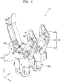
- FIG. 1 is a perspective view of a robot hand according to an embodiment of the disclosure.
- a robot hand 10 may include a body portion 100, a finger assembly 200, a finger driving unit 300, a band driving unit (not shown), and a rotation driving unit 500.
- the body portion 100 may be connected to a robot or the like.
- the body portion 100 may be rotatably connected to the robot or the like, or may be fixed to the robot or the like.
- the body portion 100 may include a support portion 110 connected to the robot or the like, and a rotating portion 120 rotatably connected to the support portion 110. In this case, there may be at least one rotating portion 120. When there is a plurality of the rotating portions 120, the rotating portions 120 may simultaneously rotate by being connected to the support portion 110.
- the body portion 100 may be connected to at least one finger assembly 200.
- the plurality of finger assemblies 200 may be spaced apart from each other.
- the plurality of finger assemblies 200 may grasp an object.
- one of the plurality of finger assemblies 200 may be rotatably connected to the support portion 110, and another one of the plurality of finger assemblies 200 may be rotatably connected to the rotating portion 120.
- the other one of the plurality of finger assemblies 200 which is connected to the rotating portion 120, may simultaneously rotate around the body portion 100 while the rotating portion 120 rotates.
- the finger assembly 200 may include a main frame 210, a tip portion 220, and a band portion 230.
- the main frame 210 may be rotatably connected to the body portion 100.
- the main frame 210 may have a structure in which a plurality of frames are connected to each other.
- the tip portion 220 may be rotatably connected to the main frame 210.
- One surface of the tip portion 220 may be flat.
- One of the tip portion 220 and the main frame 210 may include an insertion portion 600.
- the other one of the tip portion 220 or the main frame 210 may include a path guide portion 700.
- the insertion portion 600 may move by being inserted into the path guide portion 700, and the path guide portion 700 may guide movement of the insertion portion 600.
- the insertion portion 600 may have a projection shape protruding from an outer surface of one of the tip portion 220 or the main frame 210, and the path guide portion 700 may have a hole shape in a form of a long hole.
- the tip portion 220 includes the insertion portion 600 and the main frame 210 includes the path guide portion 700 will be mainly described in detail.
- the band portion 230 may be connected to the tip portion 220 to change a position of the tip portion 220.
- one side surface among one end of the tip portion 220 may be rotatably connected to the main frame 210 as described above, and another side surface among the one end of the tip portion 220 may be connected to the band portion 230.
- the band portion 230 may be flexible.
- the band portion 230 may be in a form in which synthetic resin and natural fiber are mixed.
- the band portion 230 may have a certain level of strength such that a shape thereof is changed but not stretched.
- the band portion 230 is connected to the band driving unit, and a position of one surface of the tip portion 220 may be changed according to movement of the band driving unit.
- the finger driving unit 300 may be arranged at the body portion 100 to be connected to one finger assembly 200. Here, the finger driving unit 300 may rotate the finger assembly 200 itself.
- the band driving unit may be connected to the band portion 230 to change a location of a portion of the band driving unit, which is connected to the band portion 230.
- the rotation driving unit 500 may connect the support portion 110 and the rotating portion 120.
- the rotation driving unit 500 may rotate the rotating portion 120.
- the robot hand 10 may grasp an object having an even surface or an object having an uneven surface, such as an object having a curved surface.
- the robot hand 10 may support an object by only using the tip portion 220.
- an interval between the finger assemblies 200 may be adjusted by operating the rotation driving unit 500.
- each finger assembly 200 may rotate based on the body portion 100, and thus an interval between the tip portions 220 of the finger assemblies 200may be increased or decreased.
- the rotation driving unit 500 may increase the interval between the tip portions 220 of the finger assemblies 200.
- the finger driving unit 300 may be operated to enlarge a space between the tip portions 220 of the finger assemblies 200 to correspond to a surface size of the object.
- a separately provided LiDAR, camera, or the like may be used to determine a type of the object or measure a surface of the object, and control described above may be performed based on a result of determining or measuring.
- the band driving unit may be operated such at a flat surface of the tip portion 220 of the finger assembly 200 is arranged as shown in FIG. 2 .
- the flat surface of the tip portion 220 may be arranged perpendicular to a flat top surface of the body portion 100, based on FIG. 2 .
- operations of the finger driving unit 300 and band driving unit may be controlled to adjust the space between the tip portions 220, thereby grasping the object.
- the band driving unit may change a length of the band portion 230 protruding from the body portion 100 such that the flat surface of the tip portion 220 is arranged as described above, according to the operations of the finger driving unit 300.
- a portion of the body portion 100, into or from which the band portion 230 is inserted or extracted may be curved so as to reduce friction between the band portion 230 and the body portion 100 when the band portion 230 is inserted or extracted.
- a surface of the object contacted by the tip portion 220 may be uniform.
- the flat surface of the tip portion 220 may be maintained parallel to the surface of the object so as to maximize grasping power for the object.
- the flat surface of the tip portion 220 is the same as a surface where a tangent line is arranged on an outer surface of the object, and thus the object may be prevented from slipping from the flat surface of the tip portion 220.
- the robot hand 10 may grasp an object having an uneven surface.
- a surface of the object may contact an outer surface of the band portion 230 of the finger assembly 200.
- a location of each finger assembly 200 may be adjusted by controlling the rotation driving unit 500, the finger driving unit 300, and the band driving unit. Then, when the object is completely inserted into spaces between the plurality of finger assemblies 200, the finger driving unit 300 and the band driving unit may be controlled to grasp the object.
- the main frame 210 may rotate such that the main frame 210 approaches the outer surface of the body portion 100.
- an outer surface of the band portion 230 may contact a surface of the object.
- the band driving unit may operate to adjust a position of the tip portion 220.
- the band driving unit may adjust a length of the body portion 100 extracted from the body portion 100, such that the band portion 230 is extracted from or inserted into the body portion 100.
- the tip portion 220 may rotate based on the main frame 210 according to the operation of the band driving unit, and a flat portion of the tip portion 220 may face an outer surface of the object.
- the flat portion of the tip portion 220 may face another finger assembly 200 or face a top surface of the body portion 100 in FIG. 1 .
- the insertion portion 600 may assist with a free position change of the tip portion 220 by freely moving on the path guide portion 700.
- the movements of the tip portions 220 described above may be simultaneously performed at the plurality of finger assemblies 200.
- the finger driving unit 300 does not operate, a changing degree of a shape of the band portion 230 varies depending on the uneven surface of the object, and thus the positions of the tip portions 220 of the finger assemblies 200 may also be different from each other.
- the robot hand 10 it is possible for the robot hand 10 to freely grasp an object having an uneven outer surface. Also, it is possible for the robot hand 10 to grasp an object having an even surface, through the tip portion 220.
- the robot hand 10 may improve an operation performance by operating according to various objects.
- the robot hand 10 may prevent damage to an object when grasping the object, as force applied by the band portion 230 to the object is distributed according to a shape of a surface of the object.
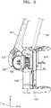
- FIG. 2 is a cross-sectional view of a finger assembly of the robot hand of FIG. 1 .
- FIG. 3 is a perspective view of a part of the finger assembly of FIG. 2 .
- the finger assembly 200 may be connected to the finger driving unit 300.
- the finger driving unit 300 may be arranged inside the support portion 110 or the rotating portion 120.
- a plurality of the finger driving units 300 may be provided to independently drive the finger assemblies 200.
- the finger driving units 300 may be individually connected to the finger assemblies 200, respectively.
- the finger driving unit 300 may include a first finger driving gear 310 connected to the finger assembly 200, a second finger driving gear 320 connected to the first finger driving gear 310, a third finger driving gear 330 connected to the second finger driving gear 320, and a first driving unit 340 connected to the third finger driving gear 330.
- the first finger driving gear 310 may be fixed to the main frame 210 or may be integrated to an outer surface of the main frame 210.
- the first finger driving gear 310 may be formed in a fan shape such that the main frame 210 operates within a uniform rotation angle range.
- the first finger driving gear 310 may include a stopper to prevent the main frame 210 from deviating from the rotation angle range.
- the stopper may have a projection shape and protrude into the body portion 100.
- a groove into which the stopper is inserted may be formed on an inner surface of the body portion 100 to limit a rotation angle of the stopper.
- the second finger driving gear 320 may be connected to the first finger driving gear 310.
- the second finger driving gear 320 may transmit driving force to the first finger driving gear 310.
- the second finger driving gear 320 may include at least one gear.
- the second finger driving gear 320 may include a first gear (not shown) and a second gear (not shown), which are connected to each other.
- the first gear may be connected to the first finger driving gear 310, and the second gear may be connected to the third finger driving gear 330.
- the third finger driving gear 330 may transmit driving force to the second finger driving gear 320.
- the third finger driving gear 330 and the second finger driving gear 320 may be arranged such that rotation shafts thereof are in different directions.
- the third finger driving gear 330 may be formed in a helical gear shape and the second finger driving gear 320 may be formed in a spur gear shape.
- the first driving unit 340 may rotate the third finger driving gear 330.
- the first driving unit 340 may include a motor.
- the first driving unit 340 may include a motor and a reducer.
- the first driving unit 340 may operate to rotate the third finger driving gear 330.
- the third finger driving gear 330 may rotate the second finger driving gear 320, and the second finger driving gear 320 may rotate the first finger driving gear 310.
- the main frame 210 may rotate according to the rotation of the first finger driving gear 310.
- a rotation direction of the main frame 210 may vary depending on a rotation direction of a rotation shaft of the first driving unit 340, according to an operation of the first driving unit 340.
- an angle formed by the main frame 210 and an outer surface of the support portion 110 or rotating portion 120 may vary.
- the main frame 210 may approach or move away from one surface of the support portion 110 or rotating portion 120, according to the operation of the finger driving unit 300.
- the object may be grasped or released according to the operation of the finger driving unit 300.
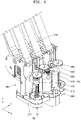
- FIG. 4 is a perspective view of a part of the robot hand of FIG. 1 .
- FIG. 5 is a plan view of a part of the robot hand of FIG. 4 .
- FIG. 6 is cross-sectional views of operations of the finger assembly of the robot hand of FIG. 2 .
- a band driving unit 400 may adjust a length of the band portion 230 of at least one finger assembly 200, which is extracted outside the body portion 100.
- one band driving unit 400 may be provided to simultaneously adjust lengths of the band portions 230 of the plurality of finger assemblies 200.
- the band driving unit 400 may be arranged inside the support portion 110.
- the band driving unit 400 may include a first driving unit 410, a first band driving gear 420, a second band driving gear 430, a third band driving gear 440, a fourth band driving gear 450, a guide portion 460, and a linear motion unit 470.
- the second driving unit 410 may be the same as or similar to the first driving unit 340 described above, and thus detailed descriptions thereof will be omitted.
- the first band driving gear 420 may be connected to the second driving unit 410.
- the second band driving gear 430 may be connected to the first band driving gear 420, and connected to the guide portion 460 connected to one of the plurality of finger assemblies 200.
- the third band driving gear 440 may be connected to the second band driving gear 430, and may be connected to the fourth band driving gear 450.
- the fourth band driving gear 450 may be connected to the guide portion 460 of another one of the finger assemblies 200, which is different from the one of the finger assemblies 200, which is connected to the second band driving gear 430.
- the third band driving gear 440 may not only transmit rotational force of the second band driving gear 430 to the fourth band driving gear 450, but also match a rotating speed of the second band driving gear 430 and a rotating speed of the fourth band driving gear 450 to be identical.
- the guide portion 460 may be connected to the second band driving gear 430 or the fourth band driving gear 450.
- a screw may be formed on an outer surface of the guide portion 460.
- the guide portion 460 may be rotatably connected to the support portion 110 to rotate according to rotation of the fourth band driving gear 450 or the second band driving gear 430.
- the linear motion unit 470 may linearly move in a length direction of the guide portion 460, along the guide portion 460 according to rotation of the guide portion 460.
- a moving direction of the linear motion unit 470 may vary according to a rotation direction of the guide portion 460.
- the linear motion unit 470 may move up and down of the guide portion 460, based on FIG. 4 , according to the rotation direction of the guide portion 460.
- a plurality of the linear motion units 470 may be provided and one end of the band portion 230 of the finger assembly 200 may be connected to each linear motion unit 470, and thus the one end of the band portion 230 may also move according to movement of the linear motion unit 470.
- the position of the tip portion 220 with respect to the main frame 210 may change according to such movement of the band driving unit 400.
- the tip portion 220 may rotate based on a portion connected to the main frame 210.
- the insertion portion 600 may move along the path guide portion 700, and a direction facing a flat portion of the tip portion 220 may be changed.
- the first band driving gear 420 may rotate to rotate the second band driving gear 430.
- the guide portion 460 connected to the second band driving gear 430 may rotate and the linear motion unit 470 may move, thereby changing the position of the tip portion 220 of one of the plurality of finger assemblies 200.
- the third band driving gear 440 and the fourth band driving gear 450 may sequentially rate at the same time.
- the guide portion 460 connected to the fourth band driving gear 450 may rotate according to the rotation of the fourth band driving gear 450, and the linear motion unit 470 may linearly move. In this case, the position of the tip portion 220 of another one of the plurality of finger assemblies 200 may change.
- ones of ends of the band portions 230 of the finger assemblies 200 which are connected to the linear motion units 470, may be linearly moved such that the tip portions 220 of the finger assemblies 200, which are connected to the other ones of the ends of the band portions 230, simultaneously maintain the same positions.
- the band driving unit 400 described above may be arranged at the support portion 110 so as not to be affected by the rotation of the main frame 210 and the rotation of the rotating portion 120.
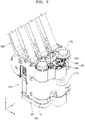
- FIG. 7 is a perspective view of a part of the robot hand of FIG. 1 .
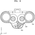
- FIG. 8 is a plan view of a part of the robot hand of FIG. 7 .
- the rotation driving unit 500 may rotate the rotating portion 120 based on the support portion 110.
- the rotation driving unit 500 may simultaneously rotate the plurality of rotating portions 120, based on the support portion 110.
- the rotation driving unit 500 may include a third driving unit 510, a first rotation driving gear 520, a second rotation driving gear 530, and a third rotation driving gear 540.
- the third driving unit 510 is the same as or similar to the first driving unit 340 described above, and thus detailed descriptions thereof will be omitted.
- the first rotation driving gear 520 may rotate by being connected to the third driving unit 510.
- the first rotation driving gear 520 may be rotatably arranged at the support portion 110.
- the second rotation driving gear 530 may be connected to the first rotation driving gear 520, and rotatably arranged at the support portion 110.
- the second rotation driving gear 530 may be a multi-stage gear, and rotate according to rotation of the first rotation driving gear 520. For example, a gear arranged at a bottom portion of the second rotation driving gear 530 may contact the first rotation driving gear 520, and a gear arranged at a top portion of the second rotation driving gear 530 may contact the third rotation driving gear 540.
- the third rotation driving gear 540 may be connected to the second rotation driving gear 530, and rotatably arranged at the support portion 110.
- the rotating portion 120 may be fixed to one end of the third rotation driving gear 540.
- a plurality of the third rotation driving gears 540 may be provided to be each connected to the rotating portion 120.
- the rotation driving unit 500 may operate when the rotating portion 120 described above rotates.
- the third driving unit 510 may rotate the first rotation driving gear 520.
- the third rotation driving gear 540 may be rotated through the second rotation driving gear 530.
- the rotating portion 120 connected to the third rotation driving gear 540 may rotate based on the support portion 110.
- the plurality of rotating portions 120 rotate based on the support portion 110, thereby changing a distance between the support portion 110 and each finger assembly 200 arranged at each rotating portion 120.
- the plurality of rotating portions 120 may rotate clockwise or counterclockwise, based on the support portion 110.
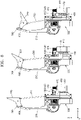
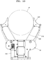
- FIG. 9 is a perspective view of an operation of the robot hand of FIG. 1 .
- FIG. 10 is a cross-sectional view of a part of the robot hand of FIG. 9 .
- like reference numerals as FIG. 6 denote like elements.
- the robot hand 10 may grasp an object M.
- the robot hand 10 may grasp the object M in various methods.
- the robot hand 10 may grasp the object M through the tip portion 220.
- the robot hand 10 may operate the first driving unit 340, based on a signal input from the outside.
- the signal input from the outside may include information about a size, shape, and the like of the object M.
- the main frame 210 may rotate.
- the separated main frames 210 may move close to or away from each other.
- An interval between the main frames 210 may be adjusted such that a space for inserting the object M is secured.
- the second driving unit 410 may operate to arrange the plurality of tip portions 220 such that one surfaces of the tip portions 220 arranged at the object M are parallel to each other. So as to algin locations of the tip portions 220 as such, a length of the band portion 230 extracted from the housing 100 may be adjusted according to operations of the second driving unit 410.
- the object M When the finger assembly 200 grasps the object M, the object M may be grasped as shown in FIG. 10 .
- FIG. 11 is a perspective view of an operation of the robot hand of FIG. 1 .
- FIG. 12 is a cross-sectional view of a part of the robot hand of FIG. 11 .
- like reference numerals as FIG. 6 denote like elements.
- the tip portion 220 when the band portion 230 is continuously inserted into the housing 100 after the tip portion 220 grasps the object M, the tip portion 220may rotate while linearly moving along the path guide portion 700.
- the insertion portion 600 may linearly move along the path guide portion 700 while rotating at the path guide portion 700 according to a location of the object M.
- the object M may move towards the band portion 230 from the tip portion 220 and contact the tip portion 220 and band portion 230.
- an outer surface of the band portion 230 may contact an outer surface of the object M, and thus have a shape similar to a shape of the outer surface of the object M.
- the outer surface of the band portion 230 may be rounded to correspond to a curved surface of the object M.
- the tip portion 220 When the linear motion unit 470 continuously moves, the tip portion 220 may completely rotate as shown in FIG. 12 to contact a top portion of the object M.
- a shape of the band portion 230 may change to correspond to the outer surface of the object M.
- the object M may be completely fixed inside the finger assembly 200 by the tip portion 220, the band portion 230, and the housing 100.
- the robot hand 10 it is possible for the robot hand 10 to grasp the object M having various outer surfaces. Also, it is possible for the robot hand 10 to grasp the object M having an uneven surface, through a simple structure.
- a finger assembly and a robot hand which are provided in a robot or the like, may be used to grasp objects of various shapes, and embodiments of the disclosure may be applied to a home robot, an industrial robot, or the like.
Landscapes
- Engineering & Computer Science (AREA)
- Robotics (AREA)
- Mechanical Engineering (AREA)
- Manipulator (AREA)
Applications Claiming Priority (2)
| Application Number | Priority Date | Filing Date | Title |
|---|---|---|---|
| KR1020200011359A KR102583215B1 (ko) | 2020-01-30 | 2020-01-30 | 핑거 어셈블리 및 이를 포함하는 로봇핸드 |
| PCT/KR2021/001008 WO2021153967A1 (ko) | 2020-01-30 | 2021-01-26 | 핑거 어셈블리 및 이를 포함하는 로봇핸드 |
Publications (2)
| Publication Number | Publication Date |
|---|---|
| EP4098413A1 true EP4098413A1 (de) | 2022-12-07 |
| EP4098413A4 EP4098413A4 (de) | 2024-02-21 |
Family
ID=77079599
Family Applications (1)
| Application Number | Title | Priority Date | Filing Date |
|---|---|---|---|
| EP21748151.4A Pending EP4098413A4 (de) | 2020-01-30 | 2021-01-26 | Fingeranordnung und roboterhand damit |
Country Status (5)
| Country | Link |
|---|---|
| US (1) | US20220362949A1 (de) |
| EP (1) | EP4098413A4 (de) |
| KR (1) | KR102583215B1 (de) |
| CN (1) | CN115003465A (de) |
| WO (1) | WO2021153967A1 (de) |
Families Citing this family (2)
| Publication number | Priority date | Publication date | Assignee | Title |
|---|---|---|---|---|
| US20250050514A1 (en) | 2022-01-18 | 2025-02-13 | The Gripper Company Aps | A Robotic Gripping Device |
| KR102896290B1 (ko) * | 2023-11-08 | 2025-12-05 | 주식회사 알파로보틱스 | 다품종 그리퍼 |
Family Cites Families (20)
| Publication number | Priority date | Publication date | Assignee | Title |
|---|---|---|---|---|
| JPS5997882A (ja) * | 1982-11-29 | 1984-06-05 | 日本電気ホームエレクトロニクス株式会社 | 物品のグリツプ装置 |
| US5108140A (en) * | 1988-04-18 | 1992-04-28 | Odetics, Inc. | Reconfigurable end effector |
| US5501498A (en) * | 1988-08-31 | 1996-03-26 | The Trustees Of The University Of Pennsylvania | Methods and apparatus for mechanically intelligent grasping |
| US6505870B1 (en) * | 2000-05-30 | 2003-01-14 | UNIVERSITé LAVAL | Actuation system for highly underactuated gripping mechanism |
| KR100451412B1 (ko) * | 2001-11-09 | 2004-10-06 | 한국과학기술연구원 | 다지 로봇 핸드 |
| DE102006009559B3 (de) * | 2006-02-28 | 2007-05-31 | Fraunhofer-Gesellschaft zur Förderung der angewandten Forschung e.V. | Greifervorrichtung sowie Verfahren zu deren Herstellung |
| JP5267213B2 (ja) * | 2009-03-02 | 2013-08-21 | 株式会社安川電機 | 多指ハンドおよびロボット |
| KR101674894B1 (ko) * | 2009-12-21 | 2016-11-10 | 삼성전자 주식회사 | 산업용 다자유도 그리퍼 |
| JP2011240422A (ja) * | 2010-05-17 | 2011-12-01 | Seiko Epson Corp | ロボットハンド、およびロボット |
| JP2012166297A (ja) * | 2011-02-14 | 2012-09-06 | Seiko Epson Corp | ロボットハンド及びロボット装置 |
| JP2014076522A (ja) * | 2012-10-11 | 2014-05-01 | Seiko Epson Corp | ロボットハンド及びロボット装置 |
| CN102873689B (zh) * | 2012-10-24 | 2017-04-12 | 中南大学 | 一种具有快速反射抓取功能的多模式欠驱动仿人手指装置 |
| EP2735406B1 (de) * | 2012-11-27 | 2018-04-04 | FESTO AG & Co. KG | Greifeinrichtung zum Greifen von Objekten |
| JP6689872B2 (ja) * | 2015-03-05 | 2020-04-28 | プレジデント アンド フェローズ オブ ハーバード カレッジ | 柔軟適応ロボットグラスパ |
| CN105150235B (zh) * | 2015-09-18 | 2017-03-01 | 山东科技大学 | 一种绳驱动三指灵巧手 |
| KR101776818B1 (ko) * | 2016-02-29 | 2017-09-11 | 한국기술교육대학교 산학협력단 | 리스트유닛을 포함하는 로봇 핸드 어셈블리 |
| US10016901B2 (en) * | 2016-05-04 | 2018-07-10 | X Development Llc | Sprung worm gripper for a robotic device |
| US9782902B1 (en) * | 2016-06-29 | 2017-10-10 | Robotis Co., Ltd. | Gripper for robot hand capabel of adaptive grasp |
| CN108247627B (zh) * | 2018-03-06 | 2024-07-02 | 苏州钧舵机器人有限公司 | 一种微型离合结构及具有该离合结构的机械手 |
| CN209936945U (zh) * | 2019-04-16 | 2020-01-14 | 中国矿业大学 | 三指机械手 |
-
2020
- 2020-01-30 KR KR1020200011359A patent/KR102583215B1/ko active Active
-
2021
- 2021-01-26 WO PCT/KR2021/001008 patent/WO2021153967A1/ko not_active Ceased
- 2021-01-26 EP EP21748151.4A patent/EP4098413A4/de active Pending
- 2021-01-26 CN CN202180010216.4A patent/CN115003465A/zh active Pending
-
2022
- 2022-07-28 US US17/815,680 patent/US20220362949A1/en active Pending
Also Published As
| Publication number | Publication date |
|---|---|
| KR20210097539A (ko) | 2021-08-09 |
| EP4098413A4 (de) | 2024-02-21 |
| KR102583215B1 (ko) | 2023-09-27 |
| WO2021153967A1 (ko) | 2021-08-05 |
| CN115003465A (zh) | 2022-09-02 |
| US20220362949A1 (en) | 2022-11-17 |
Similar Documents
| Publication | Publication Date | Title |
|---|---|---|
| US20220362949A1 (en) | Finger assembly and robot hand comprising same | |
| JP5629484B2 (ja) | 人間のような指を有するロボットハンド | |
| EP3370926B1 (de) | Unterbetätigte roboterhand | |
| EP2433760B1 (de) | Hand und Roboter | |
| US8690212B2 (en) | Robot hand | |
| US8523509B2 (en) | Robot | |
| US8181552B2 (en) | Driving apparatus and robot having the same | |
| JP2005288590A (ja) | 多関節型マニピュレータ | |
| US11660150B2 (en) | Dexterous 4-DOF surgical tool for compact articulation | |
| US20220313296A1 (en) | Surgical device | |
| KR20190052376A (ko) | 로봇 암 연장 장치 및 이를 포함하는 로봇 | |
| TW201930031A (zh) | 機器手臂 | |
| US10398410B2 (en) | Tension transmission device and three-dimensional mechanical probe using same | |
| US8789685B2 (en) | Conveying device | |
| EP0600433A1 (de) | Linear bewegender Apparat | |
| EP4311631A1 (de) | Differentialkugelgelenk mit kabelübertragung, insbesondere für die robotik | |
| JPS62140788A (ja) | 工業用ロボツトのハンド | |
| CN220801672U (zh) | 一种递送机构和介入机器人 | |
| KR20040046005A (ko) | 케이블 메카니즘을 이용한 로봇 그리퍼 | |
| US12215786B2 (en) | Orbital tensile drive | |
| KR101981928B1 (ko) | 길이 가변 기구 | |
| KR102682015B1 (ko) | 내시경 조작장치 | |
| JP2014000650A (ja) | 関節駆動機構及びロボットアーム | |
| CN120985696B (zh) | 一种灵巧手及机器人 | |
| CN209212904U (zh) | 一种防跳齿型同步带传动直线模组 |
Legal Events
| Date | Code | Title | Description |
|---|---|---|---|
| STAA | Information on the status of an ep patent application or granted ep patent |
Free format text: STATUS: THE INTERNATIONAL PUBLICATION HAS BEEN MADE |
|
| PUAI | Public reference made under article 153(3) epc to a published international application that has entered the european phase |
Free format text: ORIGINAL CODE: 0009012 |
|
| STAA | Information on the status of an ep patent application or granted ep patent |
Free format text: STATUS: REQUEST FOR EXAMINATION WAS MADE |
|
| 17P | Request for examination filed |
Effective date: 20220823 |
|
| AK | Designated contracting states |
Kind code of ref document: A1 Designated state(s): AL AT BE BG CH CY CZ DE DK EE ES FI FR GB GR HR HU IE IS IT LI LT LU LV MC MK MT NL NO PL PT RO RS SE SI SK SM TR |
|
| DAV | Request for validation of the european patent (deleted) | ||
| DAX | Request for extension of the european patent (deleted) | ||
| A4 | Supplementary search report drawn up and despatched |
Effective date: 20240122 |
|
| RIC1 | Information provided on ipc code assigned before grant |
Ipc: B25J 15/12 20060101ALI20240116BHEP Ipc: B25J 15/10 20060101ALI20240116BHEP Ipc: B25J 15/00 20060101ALI20240116BHEP Ipc: B25J 15/02 20060101AFI20240116BHEP |
|
| RAP1 | Party data changed (applicant data changed or rights of an application transferred) |
Owner name: NAVER CORPORATION Owner name: KOREA UNIVERSITY OF TECHNOLOGY AND EDUCATIONINDUSTRY-UNIVERSITY CORPORATION FOUNDATION |