EP0600433A1 - Linear bewegender Apparat - Google Patents
Linear bewegender Apparat Download PDFInfo
- Publication number
- EP0600433A1 EP0600433A1 EP93119262A EP93119262A EP0600433A1 EP 0600433 A1 EP0600433 A1 EP 0600433A1 EP 93119262 A EP93119262 A EP 93119262A EP 93119262 A EP93119262 A EP 93119262A EP 0600433 A1 EP0600433 A1 EP 0600433A1
- Authority
- EP
- European Patent Office
- Prior art keywords
- pulley
- moving
- rectilinear
- pulleys
- belt
- Prior art date
- Legal status (The legal status is an assumption and is not a legal conclusion. Google has not performed a legal analysis and makes no representation as to the accuracy of the status listed.)
- Withdrawn
Links
Images


Classifications
-
- F—MECHANICAL ENGINEERING; LIGHTING; HEATING; WEAPONS; BLASTING
- F16—ENGINEERING ELEMENTS AND UNITS; GENERAL MEASURES FOR PRODUCING AND MAINTAINING EFFECTIVE FUNCTIONING OF MACHINES OR INSTALLATIONS; THERMAL INSULATION IN GENERAL
- F16H—GEARING
- F16H19/00—Gearings comprising essentially only toothed gears or friction members and not capable of conveying indefinitely-continuing rotary motion
- F16H19/02—Gearings comprising essentially only toothed gears or friction members and not capable of conveying indefinitely-continuing rotary motion for interconverting rotary or oscillating motion and reciprocating motion
- F16H19/06—Gearings comprising essentially only toothed gears or friction members and not capable of conveying indefinitely-continuing rotary motion for interconverting rotary or oscillating motion and reciprocating motion comprising flexible members, e.g. an endless flexible member
- F16H2019/0609—Gearings comprising essentially only toothed gears or friction members and not capable of conveying indefinitely-continuing rotary motion for interconverting rotary or oscillating motion and reciprocating motion comprising flexible members, e.g. an endless flexible member the reciprocating motion being created by at least one drum or pulley with different diameters, using a differential effect
Definitions
- the present invention relates to the improvement of a rectilinear moving apparatus for use in industrial robots which is capable of rectilinearly and reciprocally moving a sliding member.
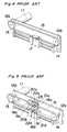
- Fig. 4 indicates the basic structure of a conventional rectilinear moving apparatus disclosed in Japanese Laid-open Patent Publication No. 2-106283.
- a driving pulley 13 having the radius (r) is coupled to a driving motor 11 is coupled via a shaft 12a.
- a shaft 12b is set parallel to the shaft 12a and coupled with an idler pulley 14.
- An endless belt 15 connects the driving pulley 13 with the idler pulley 14.
- a slider 17 is arranged so as to be kept in contact with the endless belt 15 in the middle part of the driving pulley 13 and the idler pulley 14.
- the endless belt 15 is moved the distance r ⁇ , and the slider 17 alike is moved the same distance r ⁇ . Therefore, the moving amount of the endless belt 15 by the rotation of the driving pulley 13 is equal to the moving amount of the slider 17 in the horizontal direction in the prior art arrangement.
- the apparatus disclosed in Japanese Laid-open Patent Publication No. 61-140665 is designed in such constitution as illustrated in Fig. 5.
- the shafts 12a, 12b are arranged parallel to each other, the former 12a coupling the driving motor 11 with the driving pulley 13, while the latter 12b being coupled to the idler pulley 14.
- the driving pulley 13 and the idler pulley 14 are connected with each other by the endless belt 15.
- the endless belt 15 is sent along the pulley 20a in the first half of the movement by the guide rollers 18a, 18b. On the other hand, the endless belt 15 is retained by the guide rollers 18c, 18d to trace the pulley 20b in the latter half of the movement.
- a pulley 21c is coupled with the pulley 20a by a shaft 22c, which is further coupled via an endless belt 23 with a pulley 21d connected with the pulley 20b by a shaft 22d.
- the pulley 21d has a smaller diameter than the pulley 21c.
- the driving pulley 13 When the driving motor 11 is driven, the driving pulley 13 is rotated, thereby rotating the idler pulley 14 and the pulleys 20a, 20b connected by the endless belt 15.
- the pulleys 21c, 21d coaxially provided with the pulleys 20a, 20b are rotated at this time, the pulley 20b coaxial with the pulley 21d assumes a larger rotating angle than the pulley 20a coaxial with the pulley 21c because the pulley 21d is smaller in diameter than the pulley 21c.
- the moving amount of the endless belt 15 is varied due to the difference of the rotating angles of the pulleys 20a, 20b, the slider 19 is moved half the difference of the moving amount. That is, the moving amount of the endless belt 15 subsequent to the rotation of the driving pulley 13 becomes half the difference of the diameter of the pulleys 21c and 21d.
- the object of the present invention is therefore to provide an inexpensive rectilinear moving apparatus simplified in structure which realizes the high reduction gear ratio, augments the thrust, improves the positional accuracy, and reduces the loss of movement.
- a rectilinear moving apparatus comprising: a driving motor; a driving pulley coupled to the driving motor so as to reversibly rotate; an idler pulley which axis is parallel to an axis of the driving pulley; first and second moving pulleys of different diameters formed in one unit so as to integrally rotate around a common rotary axis and arranged between the driving pulley and the idler pulley while rotary centers of the moving pulleys, the driving pulley, and the idler pulley are aligned in a straight line; an endless belt held between the driving pulley, the first and second moving pulleys, and the idler pulley to be moved by the driving motor; a rectilinear sliding member on which the first and second moving pulleys are rotatably supported and which is guided along a rectilinear direction by a rectilinear guide member; and first and second pairs of guide roller
- shafts 12a, 12b are set parallel to each other.
- a driving motor 11 and a driving pulley 13 are coupled with each other by the shaft 12a.
- the shaft 12b is coupled with an idler pulley 14 in a manner to allow the rotation of the idler pulley 14.
- the shaft 12a rotatably penetrates through a base plate 42 and the shaft 12b is fixed to the plate 42.
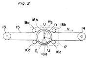
- moving pulleys 16a, 16b In the middle of an endless belt 15 supported between the driving pulley 13 and the idler pulley 14 are provided moving pulleys 16a, 16b of different diameters which have a common rotary axis.
- the pulleys 16a, 16b are formed in one unit and kept in touch with the endless belt 15.
- the rotary centers of the moving pulleys 16a and 16b, the driving pulley 13, and the idler pulley 14 are aligned in a straight line.
- a slider 17 is inclined to the plane defined by the endless belt 15, that is, the rotary plane of the driving pulley 13 and the idler pulley 14 so as to accommodate the first and second halves of the course of the backward and forward movement of the endless belt IS within the same one plane. That is, the rotary axis of the moving pulleys 16a and 16b is inclined to the rotary axes of the driving pulley 13 and the idler pulley 14 by a predetermined angle such as 20 degrees as shown in Fig. 3.
- the endless belt 15 is held by guide rollers 18a, 18b along a part of the peripheral portion of the moving pulley 16b in the first half of the course of movement. Meanwhile, the endless belt 15 is held by guide rollers 18c, 18d along a part of the peripheral portion of the moving pulley 16a in the second half of the course.
- the moving pulley 16a is smaller in diameter than the moving pulley 16b.
- the slider 17 has a thin part 17a and a thick part 17b integrally formed.
- the moving pulleys 16a and 16b, and the guide rollers 18a, 18b, 18c, and 18d are mounted on the thin part 17a.
- the thick part 17b of the slider 17 is rectilinearly and reciprocally guided by two rectilinear guide rods 40 of which both ends are fixed to the plate 42 via brackets 41.
- the rods 40 are parallel to the straight line of the centers of the pulleys 13, 14, 16a, and 16b.
- Such rectilinear guide means can be replaced with any rectilinear guide means in the prior art.
- the guide rollers 18a and 18b are arranged on the slider 17 so as to allow the belt 15 to partially move along the peripheral portion of the moving pulley 16a.
- the guide rollers 18c and 18d are arranged on the slider 17 so as to allow the belt 15 to partially move along the peripheral portion of the moving pulley 16b.
- the distance (D) between the center positions of the sections of the belt 15 in the first and second halves of the course brought in contact with the guide rollers 18a and 18c, or 18b and 18d is approximately equal to each diameter of the driving pulley 13 and the idler pulley 14.
- the driving pulley 13 has the same diameter as the idler pulley 14.
- each of the guide rollers 18a, 18b, 18c, and 18d has flanges at both ends to prevent the belt 15 from slipping from the rollers.
- the driving pulley 13, the idler pulley 14, and the moving pulleys 16a, 16b coupled by the endless belt 15 are simultaneously rotated. Since the moving pulleys 16a, 16b are formed integrally although the diameters are different, the slider 17 is moved in the horizontal direction due to the difference of the moving amounts of the endless belt 15 on the circumferences of the moving pulleys 16a, 16b. If the ratio of the diameters of the moving pulleys 16a, 16b is changed, it is possible to change the moving amount of the slider 17 to the rotating amount of the driving motor 11.
- references indicate respectively: (v) the moving amount of the endless belt 15; (u) the moving amount of the slider 17; ⁇ 1, ⁇ 2 the rotating angle of the moving pulleys 16a, 16b; and r1, r2 the radius of the moving pulleys 16a, 16b.
- the ratio of the moving amounts of the endless belt 15 and the slider 17 achieved in the constitution of the above rectilinear moving apparatus will be depicted hereinbelow.
- the endless belt 15 is held along the moving pulley 16b in the first half and along the moving pulley 16a in the second half of the course.
- the reverse can be employed, i.e., the endless belt 15 can be wound along the moving pulley 16a in the first half and along the moving pulley 16b in the second half.
- the endless belt 15 can be an endless toothed belt.
- the moving pulleys of different diameters are integrally formed and, the endless belt is held in touch with one of the moving pulleys and the other of the moving pulleys in the first half and in the second half of the course. Therefore, the rectilinear moving apparatus of the present embodiment becomes simple in structure and inexpensive, with achieving the high reduction gear, augmenting the thrust, improving the positional accuracy and reducing the loss of movement. Moreover, if the ratio of the diameters of the moving pulleys is changed, it becomes possible to change the moving amount of the slider to the rotating amount of the driving motor.
Landscapes
- Engineering & Computer Science (AREA)
- General Engineering & Computer Science (AREA)
- Mechanical Engineering (AREA)
- Transmission Devices (AREA)
- Manipulator (AREA)
Applications Claiming Priority (2)
| Application Number | Priority Date | Filing Date | Title |
|---|---|---|---|
| JP322989/92 | 1992-12-02 | ||
| JP4322989A JPH06174038A (ja) | 1992-12-02 | 1992-12-02 | 直線移動装置 |
Publications (1)
| Publication Number | Publication Date |
|---|---|
| EP0600433A1 true EP0600433A1 (de) | 1994-06-08 |
Family
ID=18149906
Family Applications (1)
| Application Number | Title | Priority Date | Filing Date |
|---|---|---|---|
| EP93119262A Withdrawn EP0600433A1 (de) | 1992-12-02 | 1993-11-30 | Linear bewegender Apparat |
Country Status (3)
| Country | Link |
|---|---|
| EP (1) | EP0600433A1 (de) |
| JP (1) | JPH06174038A (de) |
| KR (1) | KR970001128B1 (de) |
Cited By (6)
| Publication number | Priority date | Publication date | Assignee | Title |
|---|---|---|---|---|
| WO1997016659A1 (en) * | 1995-11-03 | 1997-05-09 | Brown & Sharpe Manufacturing Company | Transmission for converting rotary motion into linear motion |
| CN108223731A (zh) * | 2018-02-28 | 2018-06-29 | 广西科技大学 | 一种伸缩杆 |
| CN110388428A (zh) * | 2018-04-17 | 2019-10-29 | 费斯托股份有限两合公司 | 驱动机构 |
| CN114454147A (zh) * | 2020-11-10 | 2022-05-10 | 深圳科瑞技术股份有限公司 | 三自由度换向装置 |
| CN114683241A (zh) * | 2020-12-29 | 2022-07-01 | 中国科学院沈阳自动化研究所 | 一种肌腱传动力反馈肩肘外骨骼 |
| CN116608246A (zh) * | 2023-07-21 | 2023-08-18 | 苏州航宇九天动力技术有限公司 | 一种低温环境用同步带直线模组 |
Families Citing this family (5)
| Publication number | Priority date | Publication date | Assignee | Title |
|---|---|---|---|---|
| US6503163B1 (en) * | 1996-05-15 | 2003-01-07 | Sensar, Inc. | Precision cable drive |
| GB0416186D0 (en) * | 2004-07-20 | 2004-08-18 | Jones Tim | Improvement in and relating to activators |
| JP2007146920A (ja) * | 2005-11-25 | 2007-06-14 | Nitta Ind Corp | 直線送り装置 |
| KR101518886B1 (ko) * | 2011-12-09 | 2015-05-12 | 현대자동차 주식회사 | 액티브 롤 컨트롤 장치 |
| ES2919932T3 (es) | 2017-11-30 | 2022-07-29 | Carogusto Ag | Dispositivo con accionamiento lineal para preparar productos alimenticios |
-
1992
- 1992-12-02 JP JP4322989A patent/JPH06174038A/ja active Pending
-
1993
- 1993-11-27 KR KR1019930025466A patent/KR970001128B1/ko not_active Expired - Fee Related
- 1993-11-30 EP EP93119262A patent/EP0600433A1/de not_active Withdrawn
Non-Patent Citations (1)
| Title |
|---|
| INNOVATOR'S NOTEBOOK: "differential gears drive low cost motions", EUREKA, vol. 10, no. 6, June 1990 (1990-06-01), KENT ,GB, pages 15, XP000209904 * |
Cited By (8)
| Publication number | Priority date | Publication date | Assignee | Title |
|---|---|---|---|---|
| WO1997016659A1 (en) * | 1995-11-03 | 1997-05-09 | Brown & Sharpe Manufacturing Company | Transmission for converting rotary motion into linear motion |
| US5830094A (en) * | 1995-11-03 | 1998-11-03 | Brown & Sharpe Manufacturing Company | Transmission for converting rotary motion into linear motion |
| CN108223731A (zh) * | 2018-02-28 | 2018-06-29 | 广西科技大学 | 一种伸缩杆 |
| CN110388428A (zh) * | 2018-04-17 | 2019-10-29 | 费斯托股份有限两合公司 | 驱动机构 |
| CN114454147A (zh) * | 2020-11-10 | 2022-05-10 | 深圳科瑞技术股份有限公司 | 三自由度换向装置 |
| CN114683241A (zh) * | 2020-12-29 | 2022-07-01 | 中国科学院沈阳自动化研究所 | 一种肌腱传动力反馈肩肘外骨骼 |
| CN116608246A (zh) * | 2023-07-21 | 2023-08-18 | 苏州航宇九天动力技术有限公司 | 一种低温环境用同步带直线模组 |
| CN116608246B (zh) * | 2023-07-21 | 2023-09-22 | 苏州航宇九天动力技术有限公司 | 一种低温环境用同步带直线模组 |
Also Published As
| Publication number | Publication date |
|---|---|
| JPH06174038A (ja) | 1994-06-21 |
| KR940015310A (ko) | 1994-07-20 |
| KR970001128B1 (ko) | 1997-01-28 |
Similar Documents
| Publication | Publication Date | Title |
|---|---|---|
| EP0600433A1 (de) | Linear bewegender Apparat | |
| US4736645A (en) | Gear unit for a manipulator | |
| KR20070053206A (ko) | 액츄에이터 | |
| US5216932A (en) | X-y drive apparatus | |
| US4574655A (en) | Wrist mechanism for industrial robot | |
| KR930000493B1 (ko) | 구동 전달기구 | |
| US5477743A (en) | Two dimensional drive system | |
| US5020388A (en) | Wire guide apparatus for wire-driven mechanism | |
| US5194049A (en) | Combined directional and infinitely variable-speed transmission | |
| US4896566A (en) | Motion transforming device, and in particular a speed reduction gear | |
| US5564309A (en) | Rectilinear motion apparatus | |
| US20240140720A1 (en) | Conveying device | |
| KR100495474B1 (ko) | 벨트 차동 장치 | |
| US4642071A (en) | Toothed belt drive between oblique shafts | |
| US4904131A (en) | Chuck head for automatic machine tools | |
| JPH11165229A (ja) | 工作機械 | |
| US3398596A (en) | Gain power transmitting device | |
| ES8305102A1 (es) | "perfeccionamientos en los sitemas de transmision de par con variador incorporado". | |
| CA2041227C (en) | Device for driving a spindle for moving a part within a machine used for processing plate-shaped workpieces | |
| US4923434A (en) | High precision drive mechanism | |
| US4699016A (en) | Translatable drive apparatus | |
| US12215786B2 (en) | Orbital tensile drive | |
| JP3500836B2 (ja) | テーブル駆動装置 | |
| KR200159580Y1 (ko) | 로보트 리스트 | |
| US5149310A (en) | Differential speed reducer |
Legal Events
| Date | Code | Title | Description |
|---|---|---|---|
| PUAI | Public reference made under article 153(3) epc to a published international application that has entered the european phase |
Free format text: ORIGINAL CODE: 0009012 |
|
| 17P | Request for examination filed |
Effective date: 19931130 |
|
| AK | Designated contracting states |
Kind code of ref document: A1 Designated state(s): DE FR GB |
|
| STAA | Information on the status of an ep patent application or granted ep patent |
Free format text: STATUS: THE APPLICATION HAS BEEN WITHDRAWN |
|
| 18W | Application withdrawn |
Withdrawal date: 19940901 |