EP4098374B1 - Equipment for the enameling of manufactured articles - Google Patents
Equipment for the enameling of manufactured articles Download PDFInfo
- Publication number
- EP4098374B1 EP4098374B1 EP22185382.3A EP22185382A EP4098374B1 EP 4098374 B1 EP4098374 B1 EP 4098374B1 EP 22185382 A EP22185382 A EP 22185382A EP 4098374 B1 EP4098374 B1 EP 4098374B1
- Authority
- EP
- European Patent Office
- Prior art keywords
- orifices
- roller
- protrusions
- equipment
- fact
- Prior art date
- Legal status (The legal status is an assumption and is not a legal conclusion. Google has not performed a legal analysis and makes no representation as to the accuracy of the status listed.)
- Active
Links
Images


Classifications
-
- B—PERFORMING OPERATIONS; TRANSPORTING
- B05—SPRAYING OR ATOMISING IN GENERAL; APPLYING FLUENT MATERIALS TO SURFACES, IN GENERAL
- B05C—APPARATUS FOR APPLYING FLUENT MATERIALS TO SURFACES, IN GENERAL
- B05C5/00—Apparatus in which liquid or other fluent material is projected, poured or allowed to flow on to the surface of the work
- B05C5/02—Apparatus in which liquid or other fluent material is projected, poured or allowed to flow on to the surface of the work the liquid or other fluent material being discharged through an outlet orifice by pressure, e.g. from an outlet device in contact or almost in contact, with the work
- B05C5/0225—Apparatus in which liquid or other fluent material is projected, poured or allowed to flow on to the surface of the work the liquid or other fluent material being discharged through an outlet orifice by pressure, e.g. from an outlet device in contact or almost in contact, with the work characterised by flow controlling means, e.g. valves, located proximate the outlet
- B05C5/0229—Apparatus in which liquid or other fluent material is projected, poured or allowed to flow on to the surface of the work the liquid or other fluent material being discharged through an outlet orifice by pressure, e.g. from an outlet device in contact or almost in contact, with the work characterised by flow controlling means, e.g. valves, located proximate the outlet the valve being a gate valve or a sliding valve
- B05C5/0233—Apparatus in which liquid or other fluent material is projected, poured or allowed to flow on to the surface of the work the liquid or other fluent material being discharged through an outlet orifice by pressure, e.g. from an outlet device in contact or almost in contact, with the work characterised by flow controlling means, e.g. valves, located proximate the outlet the valve being a gate valve or a sliding valve rotating valve, e.g. rotating perforated cylinder
-
- B—PERFORMING OPERATIONS; TRANSPORTING
- B28—WORKING CEMENT, CLAY, OR STONE
- B28B—SHAPING CLAY OR OTHER CERAMIC COMPOSITIONS; SHAPING SLAG; SHAPING MIXTURES CONTAINING CEMENTITIOUS MATERIAL, e.g. PLASTER
- B28B11/00—Apparatus or processes for treating or working the shaped or preshaped articles
- B28B11/04—Apparatus or processes for treating or working the shaped or preshaped articles for coating or applying engobing layers
- B28B11/044—Apparatus or processes for treating or working the shaped or preshaped articles for coating or applying engobing layers with glaze or engobe or enamel or varnish
-
- B—PERFORMING OPERATIONS; TRANSPORTING
- B28—WORKING CEMENT, CLAY, OR STONE
- B28B—SHAPING CLAY OR OTHER CERAMIC COMPOSITIONS; SHAPING SLAG; SHAPING MIXTURES CONTAINING CEMENTITIOUS MATERIAL, e.g. PLASTER
- B28B11/00—Apparatus or processes for treating or working the shaped or preshaped articles
- B28B11/04—Apparatus or processes for treating or working the shaped or preshaped articles for coating or applying engobing layers
- B28B11/047—Apparatus or processes for treating or working the shaped or preshaped articles for coating or applying engobing layers by pooring, e.g. curtain coating
-
- B—PERFORMING OPERATIONS; TRANSPORTING
- B28—WORKING CEMENT, CLAY, OR STONE
- B28B—SHAPING CLAY OR OTHER CERAMIC COMPOSITIONS; SHAPING SLAG; SHAPING MIXTURES CONTAINING CEMENTITIOUS MATERIAL, e.g. PLASTER
- B28B17/00—Details of, or accessories for, apparatus for shaping the material; Auxiliary measures taken in connection with such shaping
- B28B17/0063—Control arrangements
- B28B17/0081—Process control
-
- B—PERFORMING OPERATIONS; TRANSPORTING
- B05—SPRAYING OR ATOMISING IN GENERAL; APPLYING FLUENT MATERIALS TO SURFACES, IN GENERAL
- B05C—APPARATUS FOR APPLYING FLUENT MATERIALS TO SURFACES, IN GENERAL
- B05C5/00—Apparatus in which liquid or other fluent material is projected, poured or allowed to flow on to the surface of the work
- B05C5/02—Apparatus in which liquid or other fluent material is projected, poured or allowed to flow on to the surface of the work the liquid or other fluent material being discharged through an outlet orifice by pressure, e.g. from an outlet device in contact or almost in contact, with the work
- B05C5/0245—Apparatus in which liquid or other fluent material is projected, poured or allowed to flow on to the surface of the work the liquid or other fluent material being discharged through an outlet orifice by pressure, e.g. from an outlet device in contact or almost in contact, with the work for applying liquid or other fluent material to a moving work of indefinite length, e.g. to a moving web
Definitions
- the present invention relates to a piece of equipment for the enameling of manufactured articles.
- a first known method involves the use of a device, in jargon called "bell", which allows the formation of a film of enamel under which the tile is passed.
- This first methodology has however a number of drawbacks.
- Another drawback of this first known method is the difficulty of applying enamel uniformly on the tiles. In fact, the quantity of applied enamel is greater at the edges of the tile and lesser in the central area.
- the film defined by the bell must have a greater extension than the tile itself, which entails a considerable waste of material.
- the enamel which falls outside the tile is generally recovered and reused.
- the recovered enamel has a different density than the original enamel, thus giving rise to color shades which are different to the initial ones.
- a second known method involves the application of the enamel by means of atomization. More specifically, this method is carried out by means of a plurality of nozzles which are adapted to atomize the enamel and which are arranged inside the relevant enameling booths.
- An enameling method of the type known in the ceramic industry to overcome the drawbacks of the aforementioned known methods provides for the application of enamel by means of a series of nozzles which are adapted to dispense a relevant strip of enamel on the manufactured article to be enameled of identical width, so that the adjacent strips join together to define a substantially homogeneous layer of enamel.
- nozzles are adapted to dispense enamel at a pressure below 1 bar, so as to allow the release of a substantially continuous thread of enamel and such as to define a strip of enamel on the manufactured article to be enameled.
- nozzles each comprise a relevant electronically-controllable shutter, which is adapted to open/close a relevant enamel exit opening.
- the enamel applied in this way features a number of shadings in the areas where the dispensed strips are joined, which affects the quality and aesthetic result of the finished product.
- US 2003/230647 describes an equipment comprising an internally hollow load-bearing body inside which is housed to measure a roller in turn provided with an internal cavity meant to receive the enamel to be dispensed.
- the load-bearing body is provided with a plurality of orifices for dispensing the enamel on the outside and the roller is in turn provided with a plurality of holes adapted to allow the transit of the enamel contained inside the roller itself towards the outside following their alignment with the above-mentioned orifices.
- the roller is also provided with a relevant protrusion adapted to close the orifices during its rotation around the relevant axis and pushed towards the internal wall of the load-bearing body by relevant elastic means.
- US 2003/23064 does not allow uniform enameling of the relevant manufactured article to be decorated, inasmuch as, due to the presence and proximity of the holes and of the protrusions defined on the relevant roller, it involves the dispensing of a plurality of lines on the manufactured article itself. Such lines are then visible on the manufactured article and give it an irregular appearance.
- patent document US 2003/23064 also has the drawback that the orifices can become blocked during normal operation, compromising the correct exit of the enamel.
- Patent document DE 4416747 describes an equipment for the enameling of manufactured articles comprising a hollow body, adapted to contain the enamel to be dispensed and provided with a plurality of orifices, inside which a cylinder is housed in turn provided with a series of cavities, so that when such cavities reach the orifices the enamel comes out towards the outside.
- WO 2017/209926 A1 discloses a coating apparatus for direct coatings with various shape comprising an internally hollow container comprising a dispensing zone defined on a lateral side and inside which a roller is housed, the roller being operable in rotation around a relevant axis for opening and close the orifices defined on the dispensing zone.
- the main aim of the present invention is to provide a piece of equipment which allows overcoming the drawbacks of the aforementioned prior art.
- the present invention aims at providing a piece of equipment which allows distributing the enamel uniformly over the surface of the relevant manufactured articles, thus obtaining a high surface quality and at the same time reducing material waste to the utmost.
- one object of the present invention is to make a piece of equipment that allows managing the amplitude, the frequency and the position of the quantity of dispensed enamel in an easy and flexible way.
- Another object of the present invention is to provide a piece of equipment which is simple to make and operate.
- Not the least object of the equipment forming the subject of the present invention is to avoid the deposit and consolidation of the enamel and, at the same time, to prevent the orifices becoming blocked.
- Yet another object is to provide a piece of equipment which does not require the use of suction systems for the disposal of the enamel particles which remain in the air after its application.
- Another object of the present invention is to provide an equipment for the enameling of manufactured articles which allows overcoming the aforementioned drawbacks of the prior art within the scope of a simple, rational, easy, efficient to use and cost-effective solution.
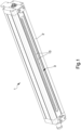
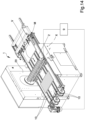
- reference numeral 1 globally indicates a piece of equipment for the enameling of manufactured articles, especially ceramic products.
- the equipment 1 comprises an internally hollow container 2 for the collection of enamel to be applied on a manufactured article M, which is provided with at least one group of through orifices for the outflow of the enamel.
- the container 2 is under pressure, e.g. between 0.5 bar and 3 bar. More specifically, the container 2 has one or more channels 12 for feeding the enamel inside it. By closing the orifices, it is also possible to make the enamel re-circulate inside the container 2 through the channels 12, the minimum number of which in this case must be two.
- the group of orifices defined on the container 2 is identified with the reference number 3, while the individual orifices are identified with the reference number 13.
- the container 2 is meant to be supported by a load-bearing frame 20 and the equipment 1 comprises movement means 10 for moving the manufactured article M to be enameled along a direction of forward movement V.
- the movement means 10 define a supporting surface of the manufactured article M placed below the orifices 13, and are composed e.g. of a plurality of motor-driven belts.
- the container 2, of the hollow type may have a cylindrical shape, in which case the group 3 of orifices 13 is preferably defined along its side wall, or it may have a box shape, in which case the group 3 of orifices 13 is defined on the wall delimiting the bottom of the container itself.
- the container 2 has a box-shaped on the outside and internally has a circular section.
- the orifices 13 are defined at the portion of the side wall of the container 2 arranged, in use, downwards.
- the container 2 therefore has a relevant axis, corresponding to its internal axis.
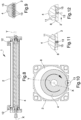
- At least one roller 4 operable in rotation around a relevant axis, identified in the figures by X.
- the roller 4 is out of axis with respect to the container 2, i.e. the axis X is misaligned with respect to the axis Y.
- the volume interposed between the inner walls of the container 2 and the roller 4 defines a containment chamber 8 of the enamel.
- the section of the containment chamber 8 is decreasing towards the orifices 13.
- the volume of the containment chamber 8 decreases moving downwards. This means that the enamel is collected at the lower section area of the containment chamber 8, near the orifices 13, thus facilitating its exit following the opening of the orifices themselves.
- the orifices 13 have a portion which extends towards the inside of the containment chamber 8, and this results in a discontinuity with respect to the wall which delimits the containment chamber itself or with respect to the inner side wall of the container 2.
- the roller 4 is provided with a plurality of protrusions adapted to open and close the orifices 13 during the rotation of the roller itself, so as to allow and prevent respectively the enamel from flowing out of the container 2.
- the set of protrusions defined on the roller 4 is identified with reference numeral 5, while the individual protrusions are identified with reference numeral 15.
- the protrusions 15 then slide on the top of the orifices 13, obstructing the access mouth thereof.
- the trajectory covered by the protrusions 15 is therefore substantially tangential to the top of the orifices 13.
- the protrusions 15 "sweep" the access mouth of the orifices 13 removing any lumps of enamel that could be deposited on the mouth and creating an effect of mixing of the enamel which prevents the sedimentation thereof.
- the roller 4 is opportunely made of elastomeric material, in order to allow the deformation of the protrusions 15 following the interaction with the orifices 13 and, thereby, ensuring the closure thereof.
- the equipment 1 comprises adjustment means for adjusting the position of the axis X of the roller 4 with respect to the container 2.
- the adjustment means therefore allow modifying the position of the axis X with respect to the axis Y of the container 2, e.g. so as to compensate for any closing inaccuracies due to the wear of the parts.
- the adjustment means can be of the mechanical type, e.g. by means of register screws or other solutions known to the person skilled in the art, or, alternatively, of the electronic type.
- the roller 4 is of the solid type. In other words, inside the roller 4 transit channels for the enamel or the like are not defined.
- the orifices 13 can be closed either simultaneously, so that the internal volume of the container 2 is isolated from the outside and no enamel can come out, or sequentially, so that the orifices 13 are closed according to a predefined sequence during the rotation of the roller 4.
- each protrusion 15 is adapted to overlap a relevant orifice 13, obstructing it, when the set 5 of protrusions 15 reaches the group 3 of orifices 13.
- each orifice 13 corresponds a relevant protrusion 15, so that there is therefore an instant when all the orifices 13 are closed by a relevant protrusion 15.
- the duration of the time interval wherein the orifices 13 remain closed depends on the rotation speed of the roller 4 and on the relevant sizes of the orifices and the protrusions themselves.
- the protrusions 15 are bigger than the orifices 13.
- the protrusions 15 can, e.g., have a parallelepiped section and the orifices 13 a circular section, although conformations of different types cannot be ruled out.
- the roller 4 has a plurality of recesses 11 defining the protrusions 15.
- the protrusions 15 are therefore defined by a series of recesses 11 obtained on the roller 4 and their external surface corresponds to the external surface of the roller itself, so they do not exceed its external diameter.
- the recesses 11 allow the transit of the enamel towards the orifices 13 during the rotation of the roller 4. More in detail, during the rotation of the roller 4, the enamel is pushed through the recesses 11 by the pressure.
- the orifices 13 are therefore opened and closed as a result of the transit over these of the recesses 11 and of the protrusions 15, respectively.
- the amplitude of the recesses 11, and therefore of the protrusions 15, determines the opening time of the orifices 13, the rotation speed of the roller 4 being equal.
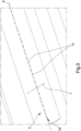
- the group 3 of orifices 13 comprises at least one row 23 of orifices 13 extending along a first direction 6.
- the orifices 13 belonging to a same row 23 are therefore substantially aligned with each other (except for machining tolerances) along the same direction 6.
- the set 5 of protrusions 15 also comprises at least one series 25 of protrusions 15 extending along the first direction 6, where the protrusions 15 arranged along each series 25 are substantially aligned (except for machining tolerances) along the first direction 6 with the orifices 13 arranged along at least one of the rows 23.
- the protrusions 15 are therefore arranged so as to be aligned with at least one relevant orifice 13 and to overlap them during the rotation of the roller 4.
- the first direction 6 is substantially parallel to the axis X of rotation of the roller 4. In the embodiment shown in the illustrations, the first direction 6 is arranged transversely to the direction of forward movement V of the manufactured article M.
- the group 3 of orifices 13 and the set 5 of protrusions 15 comprise a plurality of rows 23 and a plurality of series 25 respectively, (two in this specific case, but embodiments cannot be ruled out wherein a greater number of rows 23 and series 25 is provided), where the number of series 25 is at least equal to the number of rows 23 and where the protrusions 15 of each series 25 are aligned along the first direction 6 with the orifices 13 of at least one relevant row 23, so that the protrusions 15 overlap to the orifices 13 when the set 5 of protrusions 15 reaches the group 3 of orifices 13.
- the number of series 25 of the protrusions 15 is equal to the number of the rows 23 of orifices 13, e.g., two rows 23 and two series 25, or that the number of series 25 is greater than that of the rows 23, e.g., two rows 23 and three or four series 25, in order to increase the closing frequency of the orifices 13.
- the number of series 25 or the number of sets 5 increases, so does the number of times the orifices 13 are closed with each turn of the roller 4.
- the closing time of the orifices 13 depends on their size and on the relevant protrusions 15, as well as on the rotation speed of the roller 4, the number of series 25 or of sets 5, as well as the rotation speed of the roller 4, affects the closing frequency of the orifices 13, i.e., the number of times the orifices 13 are closed in the unit of time.
- the orifices 13 arranged along one row 23 are staggered with respect to the orifices 13 of the adjacent rows 23 along a second direction 7 substantially orthogonal to the first direction 6.
- the protrusions 15 arranged along a series 25 are staggered with respect to the protrusions 15 of the adjacent series 25 along the second direction 7, which is therefore arranged orthogonally to the axis X of the roller 4. It follows, therefore, that the first direction 6 defines a predefined angle ⁇ with the line joining the orifice/protrusion 13, 15 of a row/series 23, 25 with the nearest orifice/protrusion 13, 15 of the adjacent row/series 23, 25.
- the dispensing areas of the enamel coming out of each row 23 of orifices 13 are staggered with respect to those of the adjacent rows 23, thus allowing more uniform enameling and a better coverage of the spaces compared to the case in which the dispensing areas obtained from the adjacent rows 23 are aligned with each other.
- the distance between the adjacent rows 23 (and therefore the amplitude of the angle ⁇ ) defines the distance between the dispensing areas on the manufactured article M to be enameled along the second direction 7, while the rotation speed of the roller 4 and the sizes of the orifices 13 and of the protrusions 15, define instead the time in which the orifices 13 remain closed.
- the quantity of enamel dispensed by each orifice 13 depends instead on the opening time of the orifices 13, i.e. on the distance between the consecutive protrusions 15 responsible for closing the same orifice 13. Therefore, through the orifices 13, drops of enamel are dispensed which give rise to a substantially punctiform application on the manufactured article M. As the opening time of the orifices 13 increases, so does the size of the dispensed drop.
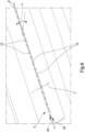
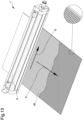
- Figure 13 shows, schematically and by way of example, the distribution of the enameled areas on a manufactured article M.
- the enamel applied is of the punctiform type and the enameled areas recover the distribution of the orifices 13 defined on the container 2.
- the parameters such as the rotation speed of the roller 4, the sizes of the orifices 13 and of the protrusions 15 and the forward movement speed of the manufactured article M, the quantity of enamel dispensed at each opening of the orifices 13 can be changed, as can the reciprocal distance of the points where the enamel is applied, so as to obtain uniform enameling both as regards the quantity of enamel dispensed on the surface of the manufactured article M and its distribution.
- the roller 4 comprises a plurality of sets of protrusions 15 angularly spaced apart from one another along the circular extension of the roller itself.
- the angular distance between each set 5 of protrusions 15 also affects the closing frequency of the orifices 13. More in particular, the smaller the angular distance between a set 5 of protrusions 15 and the next set, the greater the closing frequency of the orifices 13, the rotation speed of the roller 4 being equal. In other words, the smaller the angular distance between one set 5 of protrusions 15 and the next set, the shorter the time that elapses between two successive closures of the orifices 13, the rotation speed of the roller 4 being equal, i.e., the shorter their opening time.
- the orifices 13 are therefore opened and closed in a sequential and cyclic way, i.e., with a determinate frequency, following the transit of each set 5 of protrusions 15 at the group 3 of orifices 13 defined on the container 2.
- the container 2 comprises a single row 23 of orifices 13 and a plurality of series 25 of protrusions 15 equally spaced the one from the other over the entire extension of the external surface of the roller 4.
- This specific arrangement of the orifices 13 and of the protrusions 15 makes it possible to apply a high number of enamel points on the manufactured article M and with a high frequency.
- the Figures 11 and 12 identify the closing and opening positions of the orifices 13 respectively.
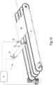
- the equipment 1 comprises motor means 14 adapted to operate the roller 4 in rotation around the axis X. More in detail, such motor means 14 comprise electronic control means for controlling the rotation of the roller 4 around the axis X.
- the equipment 1 also comprises a command and control unit 9 adapted to command the start and movement of the motor means 14. More in particular, the equipment 1 comprises sensor means 16, e.g. of the type of a photocell, operationally connected to the command and control unit 9 and adapted to detect the position of the manufactured article M to be enameled in relation to the orifices 13.
- the command and control unit 9 is also operationally connected to the movement means 10 and is programmed so as to control the rotation of the roller 4 according to the position of the manufactured article M with respect to the orifices 13 and to its forward movement speed V so as to vary the quantity and/or frequency of the enamel dispensed through the orifices themselves.
- the command and control unit 9 is configured to command the rotation of the roller 4 following the detection of the transit of the manufactured article M to be enameled and to interrupt it once such transit has been completed.
- the command and control unit 9 is therefore programmed to operate the roller 4 in rotation, thus allowing the enamel to be dispensed only when the manufactured article M passes below the orifices 13, thereby avoiding any waste of material.
- the command and control unit 9 commands the interruption of enamel dispensing, blocking the rotation of the roller 4. More specifically, the command and control unit 9 stops the roller 4 in a position wherein the protrusions 15 block the orifices 13 to prevent the transit of the enamel.
- the command and control unit 9 is configured to adjust the rotation speed of the roller 4 according to the forward movement speed of the manufactured article M and to the type of application to be obtained.
- the quantity of enamel dispensed at each opening of the orifices 13 is reduced, i.e. the size is reduced of the relevant point applied on the manufactured article M, and at the same time the dispensing frequency is increased, i.e. the distance between two consecutive dispensing operations along the direction of forward movement V is reduced, so that the dispensed enamel points are closer to one another.
- the equipment 1 with the most suitable dimensions is chosen or the closing means are adjusted in order to regulate the extension of the rows 23 of orifices 13 responsible for dispensing the enamel.
- the container 2 is then fed with enamel at a substantially constant pressure, equal to about 1 bar, which is collected inside the containment chamber 8.
- the rotation of the roller 4 is then synchronized by the command and control unit 9 with the forward movement of the manufactured article M to be enameled, so that the dispensing of the enamel through the orifices 13 starts when the manufactured article M reaches the orifices themselves and stops once it has passed them.
- the command and control unit 9 also acts on the means of control of the rotation of the roller 4 to adjust its rotation speed, according to the forward movement speed of the manufactured article M, in such a way as to vary the quantity of dispensed enamel at each opening of the orifices 13 and the dispensing frequency, i.e. the distance between two successive dispensing operations along the direction of forward movement V.
- the rotation speed of the roller 4 corresponds to the forward movement speed of the manufactured article M to be enameled.
- command and control unit 9 can intervene on the movement means 10 to vary the forward movement speed of the manufactured article M, the rotation speed of the roller 4 being equal.
- the orifices 13 are then closed by the protrusions 15 by effect of the rotation of the roller 4.
- the protrusions 15 interact with the top of the orifices 13, closing their access mouth facing inside the containment chamber 8.
- the rotation of the roller 4 conveys the sets 5 of protrusions to the group 3 of orifices 13 and, as soon as the protrusions 15 of each series 25 overlap the orifices 13 of the corresponding rows 23, the container 2 is without openings towards the outside so that the enamel does not come out.
- the reciprocal position of the orifices 13 arranged in rows 23 adjacent to one another determines the position and the distance of the areas in which the enamel is dispensed, the sizes of the orifices 13 and of the relevant protrusions 15, as well as the rotation speed of the roller 4, determine the closing time of the orifices 13, the angular distance between the sets 5 of protrusions and the rotation speed of the roller 4 determine the opening/closing frequency of the orifices 13, the distance between two consecutive protrusions 15 determines the opening time of the corresponding orifice 13 and, therefore, the quantity of enamel dispensed.
- the misalignment of the roller with respect to the container allows defining a chamber for the collection of enamel outside the roller itself and having a conformation such as to allow the collection of the enamel at the orifices, thus facilitating the exit thereof.
- the shape of the orifices, protruding towards the inside of the containment chamber ensures their correct and effective closure by the protrusions defined on the roller.
- the equipment thus conceived allows the enamel to be applied in a punctiform manner on the manufactured article M to be enameled, so as to obtain, as a result of the natural expansion of the enamel thus dispensed on the relevant surface, a uniform enameling free of aesthetic defects.
- the equipment according to the invention does not therefore have any construction or manufacturing limits and is able to adapt easily to any production requirement.
- the particular shape of the orifices, protruding towards the inside of the enamel containment chamber, and the closure "by rubbing" due to the tangential contact of the protrusions with the mouth of the orifices themselves, allows removing any residues or lumps of enamel that may deposit at this point.
- the rotary movement of the roller therefore makes it possible to keep the orifices free of any bodies that could obstruct the transit of the enamel.
- the shape of the containment chamber and the movement of the roller inside it allow the continuous mixing of the enamel, thus preventing this from depositing on the bottom and producing areas of different densities.
Landscapes
- Engineering & Computer Science (AREA)
- Chemical & Material Sciences (AREA)
- Ceramic Engineering (AREA)
- Mechanical Engineering (AREA)
- Structural Engineering (AREA)
- Automation & Control Theory (AREA)
- Closures For Containers (AREA)
- Containers And Packaging Bodies Having A Special Means To Remove Contents (AREA)
- Details Of Rigid Or Semi-Rigid Containers (AREA)
- Devices For Post-Treatments, Processing, Supply, Discharge, And Other Processes (AREA)
Priority Applications (4)
| Application Number | Priority Date | Filing Date | Title |
|---|---|---|---|
| EP22185382.3A EP4098374B1 (en) | 2018-12-14 | 2018-12-14 | Equipment for the enameling of manufactured articles |
| PL22185382.3T PL4098374T3 (pl) | 2018-12-14 | 2018-12-14 | Urządzenie do emaliowania wytworzonych wyrobów |
| PT221853823T PT4098374T (pt) | 2018-12-14 | 2018-12-14 | Equipamento para a esmaltagem de artigos manufaturados |
| ES22185382T ES3021958T3 (en) | 2018-12-14 | 2018-12-14 | Equipment for the enameling of manufactured articles |
Applications Claiming Priority (3)
| Application Number | Priority Date | Filing Date | Title |
|---|---|---|---|
| EP18842728.0A EP3894092B1 (en) | 2018-12-14 | 2018-12-14 | Equipment for the enameling of manufactured articles |
| EP22185382.3A EP4098374B1 (en) | 2018-12-14 | 2018-12-14 | Equipment for the enameling of manufactured articles |
| PCT/IB2018/060123 WO2020121050A1 (en) | 2018-12-14 | 2018-12-14 | Equipment for the enameling of manufactured articles |
Related Parent Applications (2)
| Application Number | Title | Priority Date | Filing Date |
|---|---|---|---|
| EP18842728.0A Division EP3894092B1 (en) | 2018-12-14 | 2018-12-14 | Equipment for the enameling of manufactured articles |
| EP18842728.0A Division-Into EP3894092B1 (en) | 2018-12-14 | 2018-12-14 | Equipment for the enameling of manufactured articles |
Publications (2)
| Publication Number | Publication Date |
|---|---|
| EP4098374A1 EP4098374A1 (en) | 2022-12-07 |
| EP4098374B1 true EP4098374B1 (en) | 2025-02-05 |
Family
ID=65276222
Family Applications (4)
| Application Number | Title | Priority Date | Filing Date |
|---|---|---|---|
| EP22185382.3A Active EP4098374B1 (en) | 2018-12-14 | 2018-12-14 | Equipment for the enameling of manufactured articles |
| EP18842728.0A Active EP3894092B1 (en) | 2018-12-14 | 2018-12-14 | Equipment for the enameling of manufactured articles |
| EP22185374.0A Pending EP4098373A1 (en) | 2018-12-14 | 2018-12-14 | Equipment for the enameling of manufactured articles |
| EP24151459.5A Active EP4338852B1 (en) | 2018-12-14 | 2018-12-14 | Equipment for the enameling of manufactured articles |
Family Applications After (3)
| Application Number | Title | Priority Date | Filing Date |
|---|---|---|---|
| EP18842728.0A Active EP3894092B1 (en) | 2018-12-14 | 2018-12-14 | Equipment for the enameling of manufactured articles |
| EP22185374.0A Pending EP4098373A1 (en) | 2018-12-14 | 2018-12-14 | Equipment for the enameling of manufactured articles |
| EP24151459.5A Active EP4338852B1 (en) | 2018-12-14 | 2018-12-14 | Equipment for the enameling of manufactured articles |
Country Status (5)
| Country | Link |
|---|---|
| EP (4) | EP4098374B1 (pl) |
| ES (2) | ES3056630T3 (pl) |
| PL (2) | PL4098374T3 (pl) |
| PT (2) | PT4338852T (pl) |
| WO (1) | WO2020121050A1 (pl) |
Families Citing this family (5)
| Publication number | Priority date | Publication date | Assignee | Title |
|---|---|---|---|---|
| EP3944902A1 (en) * | 2020-07-28 | 2022-02-02 | Alfa Impianti Srl | Device for glazing products and related plant |
| IT202200008447A1 (it) * | 2022-04-28 | 2023-10-28 | Tecno Italia Digital S R L | Attrezzatura per la smaltatura di manufatti |
| IT202200019578A1 (it) * | 2022-09-23 | 2024-03-23 | Tecno Italia Digital S R L | Attrezzatura e procedimento per la decorazione di manufatti ceramici |
| IT202200021117A1 (it) | 2022-10-13 | 2024-04-13 | C I Me S Soc A Responsabilita Limitata | Macchina per l’applicazione di prodotti liquidi su un manufatto lastriforme |
| IT202200025005A1 (it) | 2022-12-05 | 2024-06-05 | C I Me S Soc A Responsabilita Limitata | Macchina per l’applicazione di prodotti liquidi su manufatti lastriformi |
Family Cites Families (6)
| Publication number | Priority date | Publication date | Assignee | Title |
|---|---|---|---|---|
| DE4416747A1 (de) | 1994-05-12 | 1995-11-16 | Schmid Gmbh & Co Geb | Vorrichtung zum Behandeln von Gegenständen mit Flüssigkeit in Naßprozessen |
| US6464785B1 (en) * | 1997-12-22 | 2002-10-15 | Wolfgang Puffe | Rotary applicator head |
| US6465632B1 (en) | 2000-06-09 | 2002-10-15 | Lexicon Genetics Incorporated | Human phosphatases and polynucleotides encoding the same |
| DE10216356C1 (de) | 2002-04-13 | 2003-09-18 | Wolfgang Puffe | Rotationskopf mit Abstreifleisten |
| US7097710B2 (en) * | 2004-04-29 | 2006-08-29 | The Procter & Gamble Company | Extrusion applicator having rotational operability |
| KR102338250B1 (ko) * | 2016-05-31 | 2021-12-10 | 쓰리엠 이노베이티브 프로퍼티즈 캄파니 | 캠 다이 코팅 시스템 |
-
2018
- 2018-12-14 ES ES24151459T patent/ES3056630T3/es active Active
- 2018-12-14 EP EP22185382.3A patent/EP4098374B1/en active Active
- 2018-12-14 EP EP18842728.0A patent/EP3894092B1/en active Active
- 2018-12-14 PT PT241514595T patent/PT4338852T/pt unknown
- 2018-12-14 EP EP22185374.0A patent/EP4098373A1/en active Pending
- 2018-12-14 PL PL22185382.3T patent/PL4098374T3/pl unknown
- 2018-12-14 ES ES22185382T patent/ES3021958T3/es active Active
- 2018-12-14 PT PT221853823T patent/PT4098374T/pt unknown
- 2018-12-14 EP EP24151459.5A patent/EP4338852B1/en active Active
- 2018-12-14 WO PCT/IB2018/060123 patent/WO2020121050A1/en not_active Ceased
- 2018-12-14 PL PL24151459.5T patent/PL4338852T3/pl unknown
Also Published As
| Publication number | Publication date |
|---|---|
| PL4098374T3 (pl) | 2025-06-09 |
| EP4338852A3 (en) | 2024-06-12 |
| EP4098373A1 (en) | 2022-12-07 |
| EP4338852B1 (en) | 2025-10-08 |
| EP3894092A1 (en) | 2021-10-20 |
| WO2020121050A1 (en) | 2020-06-18 |
| PT4338852T (pt) | 2026-01-07 |
| EP4098374A1 (en) | 2022-12-07 |
| EP4338852A2 (en) | 2024-03-20 |
| ES3056630T3 (en) | 2026-02-23 |
| ES3021958T3 (en) | 2025-05-28 |
| EP3894092B1 (en) | 2026-03-18 |
| PL4338852T3 (pl) | 2026-02-16 |
| PT4098374T (pt) | 2025-04-14 |
Similar Documents
| Publication | Publication Date | Title |
|---|---|---|
| EP4098374B1 (en) | Equipment for the enameling of manufactured articles | |
| HU224885B1 (en) | Spattering apparatus | |
| DE3811260C2 (pl) | ||
| US20230338986A1 (en) | Multi-roll granule application | |
| US5858095A (en) | Shuttle cutoff for applying granules to an asphalt coated sheet | |
| US5795622A (en) | Method of rotating or oscillating a flow of granules to form a pattern on an asphalt coated sheet | |
| EP3990290B1 (en) | Machine and method for decorating items with granular materials | |
| AU2017420368B2 (en) | System and process for applying an adhesive to a moving web | |
| CA2269278A1 (en) | Method and apparatus for applying granules to an asphalt coated sheet to form a pattern having inner and outer portions | |
| KR102328514B1 (ko) | 이동중인 베이스 웹 상에 있는 접착제 패턴 | |
| US7320814B2 (en) | Methods for applying a liquid to a web | |
| DE4430749C2 (de) | Pulverbeschichtungsanlage zur Rückgewinnung nicht verbrauchten Pulvermaterials | |
| US5776541A (en) | Method and apparatus for forming an irregular pattern of granules on an asphalt coated sheet | |
| KR20070114843A (ko) | 도막 형성장치 | |
| DE2326023B2 (de) | Verfahren zum Emaillieren der Ränder von Sanitarartikeln | |
| DE102007061498B3 (de) | Verfahren und Vorrichtung zum Pulverbeschichten von Holzsubstraten | |
| JP3415564B2 (ja) | 連続塗装装置 | |
| EP4321258A1 (en) | Piece of equipment for glazing manufactured articles | |
| DE2746571C2 (de) | Vorrichtung zum Beschichten von Gegenständen | |
| JP2683957B2 (ja) | スプレーガンの付着物除去装置,及びこれを用いた造粒機,コーティング装置 | |
| DE2425698C3 (de) | Vorrichtung zum Beschichten von Gegenständen | |
| DE29900725U1 (de) | Vorrichtung zum Vereinzeln von Zuschnitten aus Papier, Kunststoff oder ähnlichen Materialien | |
| JPH0451137B2 (pl) | ||
| JP2001079456A (ja) | 意匠性プレコート鋼板の製造方法および製造装置 | |
| JPH1110040A (ja) | 板状材の製造方法および製造装置 |
Legal Events
| Date | Code | Title | Description |
|---|---|---|---|
| PUAI | Public reference made under article 153(3) epc to a published international application that has entered the european phase |
Free format text: ORIGINAL CODE: 0009012 |
|
| STAA | Information on the status of an ep patent application or granted ep patent |
Free format text: STATUS: THE APPLICATION HAS BEEN PUBLISHED |
|
| AC | Divisional application: reference to earlier application |
Ref document number: 3894092 Country of ref document: EP Kind code of ref document: P |
|
| AK | Designated contracting states |
Kind code of ref document: A1 Designated state(s): AL AT BE BG CH CY CZ DE DK EE ES FI FR GB GR HR HU IE IS IT LI LT LU LV MC MK MT NL NO PL PT RO RS SE SI SK SM TR |
|
| STAA | Information on the status of an ep patent application or granted ep patent |
Free format text: STATUS: REQUEST FOR EXAMINATION WAS MADE |
|
| 17P | Request for examination filed |
Effective date: 20230328 |
|
| RBV | Designated contracting states (corrected) |
Designated state(s): AL AT BE BG CH CY CZ DE DK EE ES FI FR GB GR HR HU IE IS IT LI LT LU LV MC MK MT NL NO PL PT RO RS SE SI SK SM TR |
|
| RIC1 | Information provided on ipc code assigned before grant |
Ipc: B28B 17/00 20060101ALI20240717BHEP Ipc: B28B 11/04 20060101ALI20240717BHEP Ipc: B05C 5/02 20060101AFI20240717BHEP |
|
| GRAP | Despatch of communication of intention to grant a patent |
Free format text: ORIGINAL CODE: EPIDOSNIGR1 |
|
| STAA | Information on the status of an ep patent application or granted ep patent |
Free format text: STATUS: GRANT OF PATENT IS INTENDED |
|
| INTG | Intention to grant announced |
Effective date: 20240903 |
|
| GRAS | Grant fee paid |
Free format text: ORIGINAL CODE: EPIDOSNIGR3 |
|
| GRAA | (expected) grant |
Free format text: ORIGINAL CODE: 0009210 |
|
| STAA | Information on the status of an ep patent application or granted ep patent |
Free format text: STATUS: THE PATENT HAS BEEN GRANTED |
|
| AC | Divisional application: reference to earlier application |
Ref document number: 3894092 Country of ref document: EP Kind code of ref document: P |
|
| AK | Designated contracting states |
Kind code of ref document: B1 Designated state(s): AL AT BE BG CH CY CZ DE DK EE ES FI FR GB GR HR HU IE IS IT LI LT LU LV MC MK MT NL NO PL PT RO RS SE SI SK SM TR |
|
| REG | Reference to a national code |
Ref country code: GB Ref legal event code: FG4D |
|
| REG | Reference to a national code |
Ref country code: CH Ref legal event code: EP |
|
| REG | Reference to a national code |
Ref country code: IE Ref legal event code: FG4D |
|
| REG | Reference to a national code |
Ref country code: DE Ref legal event code: R096 Ref document number: 602018079010 Country of ref document: DE |
|
| P01 | Opt-out of the competence of the unified patent court (upc) registered |
Free format text: CASE NUMBER: APP_6382/2025 Effective date: 20250206 |
|
| REG | Reference to a national code |
Ref country code: PT Ref legal event code: SC4A Ref document number: 4098374 Country of ref document: PT Date of ref document: 20250414 Kind code of ref document: T Free format text: AVAILABILITY OF NATIONAL TRANSLATION Effective date: 20250409 |
|
| REG | Reference to a national code |
Ref country code: ES Ref legal event code: FG2A Ref document number: 3021958 Country of ref document: ES Kind code of ref document: T3 Effective date: 20250528 |
|
| REG | Reference to a national code |
Ref country code: NL Ref legal event code: MP Effective date: 20250205 |
|
| PG25 | Lapsed in a contracting state [announced via postgrant information from national office to epo] |
Ref country code: RS Free format text: LAPSE BECAUSE OF FAILURE TO SUBMIT A TRANSLATION OF THE DESCRIPTION OR TO PAY THE FEE WITHIN THE PRESCRIBED TIME-LIMIT Effective date: 20250505 |
|
| PG25 | Lapsed in a contracting state [announced via postgrant information from national office to epo] |
Ref country code: FI Free format text: LAPSE BECAUSE OF FAILURE TO SUBMIT A TRANSLATION OF THE DESCRIPTION OR TO PAY THE FEE WITHIN THE PRESCRIBED TIME-LIMIT Effective date: 20250205 |
|
| REG | Reference to a national code |
Ref country code: LT Ref legal event code: MG9D |
|
| PG25 | Lapsed in a contracting state [announced via postgrant information from national office to epo] |
Ref country code: IS Free format text: LAPSE BECAUSE OF FAILURE TO SUBMIT A TRANSLATION OF THE DESCRIPTION OR TO PAY THE FEE WITHIN THE PRESCRIBED TIME-LIMIT Effective date: 20250605 Ref country code: NO Free format text: LAPSE BECAUSE OF FAILURE TO SUBMIT A TRANSLATION OF THE DESCRIPTION OR TO PAY THE FEE WITHIN THE PRESCRIBED TIME-LIMIT Effective date: 20250505 |
|
| PG25 | Lapsed in a contracting state [announced via postgrant information from national office to epo] |
Ref country code: NL Free format text: LAPSE BECAUSE OF FAILURE TO SUBMIT A TRANSLATION OF THE DESCRIPTION OR TO PAY THE FEE WITHIN THE PRESCRIBED TIME-LIMIT Effective date: 20250205 |
|
| PG25 | Lapsed in a contracting state [announced via postgrant information from national office to epo] |
Ref country code: HR Free format text: LAPSE BECAUSE OF FAILURE TO SUBMIT A TRANSLATION OF THE DESCRIPTION OR TO PAY THE FEE WITHIN THE PRESCRIBED TIME-LIMIT Effective date: 20250205 |
|
| PG25 | Lapsed in a contracting state [announced via postgrant information from national office to epo] |
Ref country code: LV Free format text: LAPSE BECAUSE OF FAILURE TO SUBMIT A TRANSLATION OF THE DESCRIPTION OR TO PAY THE FEE WITHIN THE PRESCRIBED TIME-LIMIT Effective date: 20250205 |
|
| PG25 | Lapsed in a contracting state [announced via postgrant information from national office to epo] |
Ref country code: GR Free format text: LAPSE BECAUSE OF FAILURE TO SUBMIT A TRANSLATION OF THE DESCRIPTION OR TO PAY THE FEE WITHIN THE PRESCRIBED TIME-LIMIT Effective date: 20250506 Ref country code: BG Free format text: LAPSE BECAUSE OF FAILURE TO SUBMIT A TRANSLATION OF THE DESCRIPTION OR TO PAY THE FEE WITHIN THE PRESCRIBED TIME-LIMIT Effective date: 20250205 |
|
| REG | Reference to a national code |
Ref country code: AT Ref legal event code: MK05 Ref document number: 1764803 Country of ref document: AT Kind code of ref document: T Effective date: 20250205 |
|
| PG25 | Lapsed in a contracting state [announced via postgrant information from national office to epo] |
Ref country code: SE Free format text: LAPSE BECAUSE OF FAILURE TO SUBMIT A TRANSLATION OF THE DESCRIPTION OR TO PAY THE FEE WITHIN THE PRESCRIBED TIME-LIMIT Effective date: 20250205 |
|
| PG25 | Lapsed in a contracting state [announced via postgrant information from national office to epo] |
Ref country code: SM Free format text: LAPSE BECAUSE OF FAILURE TO SUBMIT A TRANSLATION OF THE DESCRIPTION OR TO PAY THE FEE WITHIN THE PRESCRIBED TIME-LIMIT Effective date: 20250205 |
|
| PG25 | Lapsed in a contracting state [announced via postgrant information from national office to epo] |
Ref country code: DK Free format text: LAPSE BECAUSE OF FAILURE TO SUBMIT A TRANSLATION OF THE DESCRIPTION OR TO PAY THE FEE WITHIN THE PRESCRIBED TIME-LIMIT Effective date: 20250205 |
|
| PG25 | Lapsed in a contracting state [announced via postgrant information from national office to epo] |
Ref country code: AT Free format text: LAPSE BECAUSE OF FAILURE TO SUBMIT A TRANSLATION OF THE DESCRIPTION OR TO PAY THE FEE WITHIN THE PRESCRIBED TIME-LIMIT Effective date: 20250205 |
|
| PG25 | Lapsed in a contracting state [announced via postgrant information from national office to epo] |
Ref country code: EE Free format text: LAPSE BECAUSE OF FAILURE TO SUBMIT A TRANSLATION OF THE DESCRIPTION OR TO PAY THE FEE WITHIN THE PRESCRIBED TIME-LIMIT Effective date: 20250205 Ref country code: CZ Free format text: LAPSE BECAUSE OF FAILURE TO SUBMIT A TRANSLATION OF THE DESCRIPTION OR TO PAY THE FEE WITHIN THE PRESCRIBED TIME-LIMIT Effective date: 20250205 |
|
| PG25 | Lapsed in a contracting state [announced via postgrant information from national office to epo] |
Ref country code: RO Free format text: LAPSE BECAUSE OF FAILURE TO SUBMIT A TRANSLATION OF THE DESCRIPTION OR TO PAY THE FEE WITHIN THE PRESCRIBED TIME-LIMIT Effective date: 20250205 |
|
| PG25 | Lapsed in a contracting state [announced via postgrant information from national office to epo] |
Ref country code: SK Free format text: LAPSE BECAUSE OF FAILURE TO SUBMIT A TRANSLATION OF THE DESCRIPTION OR TO PAY THE FEE WITHIN THE PRESCRIBED TIME-LIMIT Effective date: 20250205 |
|
| REG | Reference to a national code |
Ref country code: DE Ref legal event code: R097 Ref document number: 602018079010 Country of ref document: DE |
|
| PGFP | Annual fee paid to national office [announced via postgrant information from national office to epo] |
Ref country code: PT Payment date: 20251124 Year of fee payment: 8 |
|
| PLBE | No opposition filed within time limit |
Free format text: ORIGINAL CODE: 0009261 |
|
| STAA | Information on the status of an ep patent application or granted ep patent |
Free format text: STATUS: NO OPPOSITION FILED WITHIN TIME LIMIT |
|
| 26N | No opposition filed |
Effective date: 20251106 |
|
| PGFP | Annual fee paid to national office [announced via postgrant information from national office to epo] |
Ref country code: IT Payment date: 20251219 Year of fee payment: 8 |
|
| PGFP | Annual fee paid to national office [announced via postgrant information from national office to epo] |
Ref country code: TR Payment date: 20251121 Year of fee payment: 8 |
|
| PGFP | Annual fee paid to national office [announced via postgrant information from national office to epo] |
Ref country code: PL Payment date: 20251118 Year of fee payment: 8 |
|
| REG | Reference to a national code |
Ref country code: DE Ref legal event code: R081 Ref document number: 602018079010 Country of ref document: DE Owner name: SYSTEM CERAMICS S.P.A., FIORANO MODENESE, IT Free format text: FORMER OWNER: TECNO ITALIA DIGITAL S.R.L., FIORANO MODENESE, MO, IT |