EP4098091A1 - Kultivator mit zentraler spannvorrichtung - Google Patents
Kultivator mit zentraler spannvorrichtung Download PDFInfo
- Publication number
- EP4098091A1 EP4098091A1 EP22000134.1A EP22000134A EP4098091A1 EP 4098091 A1 EP4098091 A1 EP 4098091A1 EP 22000134 A EP22000134 A EP 22000134A EP 4098091 A1 EP4098091 A1 EP 4098091A1
- Authority
- EP
- European Patent Office
- Prior art keywords
- profile
- support tube
- profiles
- tools
- cultivator
- Prior art date
- Legal status (The legal status is an assumption and is not a legal conclusion. Google has not performed a legal analysis and makes no representation as to the accuracy of the status listed.)
- Granted
Links
Images



Classifications
-
- A—HUMAN NECESSITIES
- A01—AGRICULTURE; FORESTRY; ANIMAL HUSBANDRY; HUNTING; TRAPPING; FISHING
- A01B—SOIL WORKING IN AGRICULTURE OR FORESTRY; PARTS, DETAILS, OR ACCESSORIES OF AGRICULTURAL MACHINES OR IMPLEMENTS, IN GENERAL
- A01B39/00—Machines specially adapted for working soil on which crops are growing
- A01B39/20—Tools; Details
- A01B39/22—Tools; Mounting tools
-
- A—HUMAN NECESSITIES
- A01—AGRICULTURE; FORESTRY; ANIMAL HUSBANDRY; HUNTING; TRAPPING; FISHING
- A01B—SOIL WORKING IN AGRICULTURE OR FORESTRY; PARTS, DETAILS, OR ACCESSORIES OF AGRICULTURAL MACHINES OR IMPLEMENTS, IN GENERAL
- A01B35/00—Other machines for working soil
- A01B35/20—Tools; Details
- A01B35/22—Non-rotating tools; Resilient or flexible mounting of rigid tools
-
- A—HUMAN NECESSITIES
- A01—AGRICULTURE; FORESTRY; ANIMAL HUSBANDRY; HUNTING; TRAPPING; FISHING
- A01B—SOIL WORKING IN AGRICULTURE OR FORESTRY; PARTS, DETAILS, OR ACCESSORIES OF AGRICULTURAL MACHINES OR IMPLEMENTS, IN GENERAL
- A01B63/00—Lifting or adjusting devices or arrangements for agricultural machines or implements
- A01B63/14—Lifting or adjusting devices or arrangements for agricultural machines or implements for implements drawn by animals or tractors
- A01B63/24—Tools or tool-holders adjustable relatively to the frame
- A01B63/245—Tools or tool-holders adjustable relatively to the frame laterally adjustable
-
- A—HUMAN NECESSITIES
- A01—AGRICULTURE; FORESTRY; ANIMAL HUSBANDRY; HUNTING; TRAPPING; FISHING
- A01B—SOIL WORKING IN AGRICULTURE OR FORESTRY; PARTS, DETAILS, OR ACCESSORIES OF AGRICULTURAL MACHINES OR IMPLEMENTS, IN GENERAL
- A01B39/00—Machines specially adapted for working soil on which crops are growing
- A01B39/02—Machines specially adapted for working soil on which crops are growing with non-rotating tools
Definitions
- the invention relates to a cultivator, the frame of which has at least one longitudinal beam and at least one support tube arranged transversely thereto, on which a number of tools for tilling the soil can be attached in any position.
- Cultivators are used for mechanical weed control, which is gaining in importance due to the restrictions on the use of herbicides.
- the tools work the field between row crops, for example. Very different tools can be used for this.
- the row crops have a wide variety of row widths because the plant spacing depends on the plant species and region. The distances must therefore be readjusted in each case. This is time-consuming, especially with small planting distances.
- the invention is based on the object of designing a cultivator in such a way that the tools sitting on the support tube can be fixed or loosened with a common mechanism. According to the invention that is achieved according to the characterizing part of the 1st claim.
- V-profiles and V-grooves include profiles or grooves with at least partially convergent surfaces to understand.
- the second V-profile which can be pivoted about an axis arranged in the longitudinal direction of the support tube, serves to release or fix all tools at the same time.
- two-armed levers are firmly connected to the V-profile at one end and an actuator acts at the other end. In this way, the tools can be positioned according to the respective row width and subsequently fixed by the actuator.
- the longitudinal extension of the movable second V-profile makes it possible to get by with just a few actuators.
- the V-grooves of the individual tools each have an elastic element that ensures that the contact pressure of the V-profiles is approximately the same for all tools, regardless of tolerances.
- the V-profiles and V-grooves can be realized in two embodiments: To clamp the tools, either the edges of the V-profiles can extend outwards and engage in V-grooves of the head parts, which are open to the inside. Or the edges of the V-profiles reach inward and engage in the V-grooves of the headboard that are open to the outside. In the first case, the second V-profile is moved outwards by the actuator, in the second case inwards.
- V-profiles extending over the entire length or part of it offers great freedom in the arrangement of the actuators.
- one is sufficient.
- two or three are sufficient for a support tube.
- all actuators can be controlled together, preferably from the tractor cab.
- several support tubes, each with a row of tools, are usually arranged one behind the other in the direction of travel. Even then, all actuators can be controlled together.
- the support tube and V-profile are divided and connected to one another via hinges. So the outer parts of the support tubes and the V-profiles can have their own actuators. It can then be unfolded without further intervention.
- a support tube 1 is shown in section from the frame of a cultivator and a longitudinal beam 2 is indicated.
- the support tube 1 is here in cross section a rectangle, on the front side in the direction of travel a first V-profile 4 is provided with an edge 9 . It (4) extends over the entire length of the support tube 1.
- a second equally long second V-profile 5 is arranged pivotably. For this purpose, it is connected to an actuator 7 in places via levers 6 .
- the lever 6 can be pivoted about an axis 8 fixed to the support tube 1 .
- the lever here has two arms.
- the edges 9 of the V-profiles 4.5 are in the embodiment of 1 turned away from each other.
- a V-profile is to be understood as meaning a profile which has two convergent surfaces, or at least two convergent surface sections. So it could be a trapezoidal cross-section, or even a circular cross-section. In the case of the first V-profile, it could even be combined with any cross-section of the supporting tube.
- a tool 10 for tilling the soil can be moved and locked with its head part 11 on the support tube 1 .
- it has a first and a second V-groove 12, 13, into which the V-profiles 4.5 fit.
- the definition of the V-profile applies analogously to the V-grooves.
- the rear V-groove 12 has a rubber block 18 as an elastic element on its upper wall and a metal plate 17 above it. The rubber block 18 compensates for tolerances and unevenness in the head parts, so that all tools are clamped with approximately the same force.
- the small plate 17 is used to protect the rubber block 18. If the rubber block can also be deformed in the direction of thrust, the individual tools can be easily hung and unhooked individually.
- the actuator 7 can be electric, hydraulic or mechanical. In extremis, it could also be operated manually.
- the same reference numbers increased by 100 are used.
- the edges 109 of the V-profiles 104,105 reach inwards and engage in V-grooves 112,113 of the head parts 111, which are open to the outside.
- the second V profile 105 is acted upon inwardly by the actuator 107.
- it is connected to the actuator 107 via a lever 106 that can be pivoted about an axis 108 .
- the first V-profile 104 is arranged under the support tube 101 and is firmly connected to it.
- FIG. 4 shows as a first varied detail the design of the elastic element as a spring, as a leaf spring or disc springs 25.
- figure 5 shows as a second varied detail the design of the elastic element as a spiral spring or leg spring 26 or hairpin spring. It is attached to the head part 11 .
- a leg 27 of the leg spring 26 forms the upper limit of the V-groove 13 and carries the small plate 28.
- the second V-profile 5 acts on this.
- FIG. 6 shows the support tube 1 with the two V-profiles 12,13 and indicated the two longitudinal beams 2, seen from above.
- Supporting tube 1 and V-profiles 12,13 are cut up for road transport and their outer parts 31,32 can be folded up on 30 hinges.
- a number of tools 10 are arranged on the support tube 1 .
- actuators 7 are provided, one for each part of the cut V-profile. Their energy or pressurized oil supply is combined in a central connection 35 which is connected to a towing vehicle. In this way, all tools 10 can be fixed, loosened or completely ejected comfortably from the tractor cab. This also applies to the normal case that several support tubes with tools are arranged one behind the other.
- the actuator or actuators can be designed as desired and the profiles can be trapezoidal or circular with a corresponding design of the head parts, as long as there are only pairs of convergent surface parts.
- a circular profile could be found on lever 6 and/or even be rotatable about the axis 8.
- the two sides of the support tube can be either left and right (or front and rear) or right and left (or rear and front).
Landscapes
- Life Sciences & Earth Sciences (AREA)
- Engineering & Computer Science (AREA)
- Mechanical Engineering (AREA)
- Soil Sciences (AREA)
- Environmental Sciences (AREA)
- Zoology (AREA)
- Soil Working Implements (AREA)
- Agricultural Machines (AREA)
Abstract
Description
- Die Erfindung betrifft einen Kultivator, dessen Rahmen zumindest einen Längsträger und mindestens ein quer dazu angeordnetes Tragrohr besitzt, an dem eine Anzahl von Werkzeugen zur Bodenbearbeitung in beliebiger Position anbringbar ist.
- Kultivatoren dienen der mechanischen Unkrautbekämpfung, die durch die Einschränkungen beim Einsatz von Herbiziden an Bedeutung gewinnt. Die Werkzeuge bearbeiten den Acker beispielsweise zwischen Reihenkulturen. Dabei können sehr verschiedene Werkzeuge eingesetzt werden. Die Reihenkulturen weisen die verschiedensten Reihenweiten auf, weil die Pflanzenabstände von Pflanzenart und Region abhängig sind. Die Abstände müssen somit jeweils neu eingestellt werden. Das ist vor allem bei kleinen Pflanzabständen zeitraubend.
- Aus der
EP 31 55 885 A1 ist eine Vorrichtung mit Werkzeugen bekannt, die auf ihrem Tragrohr verschiebbar und so in beliebiger Position festsetzbar sind. Dazu müssen die Werkzeuge einzeln gelöst, auf dem Tragrohr verschoben und wieder festgeschraubt werden. Auf einem Tragrohr können bis zu 30 und mehr Werkzeuge angebracht sein. Die Umstellung jedes einzelnen Werkzeuges ist mühselig und zeitraubend, besonders bei großer Anzahl. - Der Erfindung liegt die Aufgabe zugrunde, einen Kultivator so auszubilden, dass die auf dem Tragrohr sitzenden Werkzeuge mit einem gemeinsamen Mechanismus fixiert bzw. gelockert werden können. Erfindungsgemäß wird das gemäß dem Kennzeichnungsteil des 1. Anspruchs erreicht.
- Das Zusammenwirken der gemeinsamen sich über die ganze Länge des Tragrohres erstreckenden V-Profile mit den einzelnen V-Nuten der einzelnen Kopfteile der Werkzeuge sorgt für genaue und für alle Werkzeuge gleiche Positionierung in ihrer längsgerichteten Vertikalebene. Unter V-Profilen und V-Nuten sind Profile bzw Nuten mit zumindest teilweise konvergenten Flächen zu verstehen. Das um eine in Längsrichtung des Tragrohres angeordnete Achse schwenkbare zweite V-Profil dient der gleichzeitigen Freigabe oder Festlegung aller Werkzeuge. Dazu sind zweiarmige Hebel an einem Ende mit dem V-Profil fest verbunden, am anderen Ende greift ein Aktuator an. So können die Werkzeuge entsprechend der jeweiligen Reihenweite positioniert und in der Folge vom Aktuator festgesetzt werden. Die Längserstreckung des beweglichen zweiten V-Profiles erlaubt es, mit nur wenigen Aktuatoren auszukommen.
- Um einen festen Sitz aller Werkzeuge zu erreichen, weisen die V-Nuten der einzelnen Werkzeuge jeweils ein elastisches Element auf, das unabhängig von Toleranzen einen für alle Werkzeuge ungefähr gleichen Anpressdruck der V-Profile sicherstellt.
- Die V-Profile und V-Nuten können in zwei Ausführungsformen verwirklicht sein: Zum Festklemmen der Werkzeuge können entweder die Kanten der V-Profile auswärts reichen und in nach innen offene V-Nuten der Kopfteile eingreifen. Oder die Kanten der V-Profile reichen einwärts und greifen in nach außen offene V-Nuten der Kopfteile ein. Im ersten Fall wird das zweite V-Profil vom Aktuator auswärts bewegt, in zweiten Fall einwärts.
- Auch für die Ausbildung der elastischen Elemente gibt es verschiedene vorteilhafte Lösungen. Die Wahl zwischen diesen wird von den klimatischen Bedingungen und von der Art der Werkzeuge bestimmt.
- Das Festklemmen der einzelnen Werkzeuge mittels sich über die ganze Länge, oder einen Teil dieser, erstreckender V-Profile bietet große Freiheit in der Anordnung der Aktuatoren. Im einfachsten Fall genügt ein einziger. Meist sind zwei oder drei für ein Tragrohr ausreichend. Dann sind alle Aktuatoren gemeinsam ansteuerbar, vorzugsweise von der Traktorkabine aus. In einem Kultivator sind in der Regel mehrere Tragrohre mit jeweils einer Reihe von Werkzeugen in Fahrtrichtung hintereinander angeordnet. Auch dann sind alle Aktuatoren gemeinsam ansteuerbar.
- Bei Kultivatoren mit großer Arbeitsbreite müssen für den Straßentransport Teile auf- oder umgeklappt werden. Das ist in der erfindungsgemäßen Konstruktion leicht lösbar: Tragrohr und V-Profile sind geteilt und über Scharniere miteinander verbunden. So können die äußeren Teile der Tragrohre und der V-Profile ihre eigenen Aktuatoren haben. Das Aufklappen ist dann ohne weitere Eingriffe möglich.
- Im Folgenden wird die Erfindung anhand von Zeichnungen verschiedener Ausführungsbeispiele beschrieben und erläutert. Es stellen dar:
-
Fig. 1 : Eine erste Ausführungsform in Klemmstellung, -
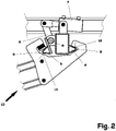
Fig. 2 : Dieselbe in offener Stellung, -
Fig. 3 : Eine zweite Ausführungsform in Klemmstellung, -
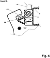
Fig. 4 : Detail A inFig. 1 in einer ersten Variante, -
Fig. 5 : Detail A inFig. 1 in einer zweiten Variante, -
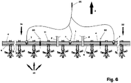
Fig. 6 : Eine gesamt - Draufsicht aufFig. 1 . - In
Fig. 1 ist von dem Rahmen eines Kultivators nur ein Tragrohr 1 im Schnitt gezeigt und ein Längsträger 2 angedeutet. Meist sind mehrere Tragrohre 1 in Fahrtrichtung 3 hintereinander angeordnet. Die in derFig. 1 linke Seite des Tragrohres ist somit hinten und die rechte in Fahrtrichtung vorne, oder umgekehrt. Das Tragrohr 1 ist hier im Querschnitt ein Rechteck, an dessen in Fahrtrichtung vorderer Seite ein erstes V-Profil 4 mit einer Kante 9 vorgesehen ist. Es (4) erstreckt sich über die ganze Länge des Tragrohres 1. An der hinteren Seite des Tragrohres 1 ist ein zweites ebenso langes zweites V-Profil 5 schwenkbar angeordnet. Dazu ist es stellenweise über Hebel 6 mit einem Aktuator 7 verbunden. Der Hebel 6 ist um eine am Tragrohr 1 befestigte Achse 8 schwenkbar. Der Hebel ist hier zweiarmig. Die Kanten 9 der V-Profile 4,5 sind in der Ausführungsform derFig. 1 einander abgewandt. - Unter einem V-Profil ist ein Profil zu verstehen, das zwei konvergente Flächen, oder zumindest zwei konvergente Flächenabschnitte, aufweist. Es könnte also ein Trapezquerschnitt, oder sogar ein Kreisquerschnitt sein. Im Fall des ersten V-Profils könnte es sogar mit dem beliebigen Querschnitt des Tragrohres vereint sein.
- Ein Werkzeug 10 zur Bodenbearbeitung ist mit seinem Kopfteil 11 am Tragrohr 1 verschiebbar und arretierbar. Dazu hat es eine erste und eine zweite V-Nut 12, 13, in welche die V-Profile 4,5 passen. Für die V-Nuten gilt die Definition der V-Profile analog. Die hintere V-Nut 12 hat an ihrer oberen Wand einen Gummiblock 18 als elastisches Element und darüber ein Plättchen 17 aus Metall. Der Gummiblock 18 gleicht Toleranzen und Unebenheiten der Kopfteile aus, sodass alle Werkzeuge mit ungefähr derselben Kraft eingespannt sind.
- Das Plättchen 17 dient der Schonung des Gummiblocks 18. Wenn der Gummiblock auch in Schubrichtung verformbar ist, können die einzelnen Werkzeuge leichter einzeln aus- und eingehängt werden.
-
Fig. 2 zeigt die Ausführungsform derFig. 1 in offener Stellung, in der die Werkzeuge am Tragrohr 1 verschiebbar oder bei weiterer Öffnung sogar abnehmbar sind. Der Aktuator 7 kann elektrisch, hydraulisch oder mechanisch sein. In Extremis könnte er auch manuell betätigt sein. - In der Variante der
Fig. 3 werden dieselben Bezugszeichen, erhöht um 100, verwendet. Die Kanten 109 der V-Profile 104,105 reichen einwärts und greifen in nach außen offene V-Nuten 112,113 der Kopfteile 111 ein. Zum Festklemmen der Werkzeuge 10 wird hier das zweite V-Profil 105 vom Aktuator 107 einwärts beaufschlagt. Dazu ist es über einen um eine Achse 108 schwenkbaren Hebel 106 mit dem Aktuator 107 verbunden. Das erste V-Profil 104 ist unter dem Tragrohr 101 angeordnet und mit diesem fest verbunden. -
Fig. 4 zeigt als erstes variiertes Detail die Ausführung des elastischen Elements als Feder, als Blattfeder oder Tellerfedern 25. -
Fig. 5 zeigt als zweites variiertes Detail die Ausführung des elastischen Elements als Spiralfeder oder Schenkelfeder 26 bzw Haarnadelfeder. Sie ist am Kopfteil 11 befestigt. Ein Schenkel 27 der Schenkelfeder 26 bildet die obere Begrenzung der V-Nut 13 und trägt das Plättchen 28. An diesem greift das zweite V-Profil 5 an. -
Fig. 6 zeigt das Tragrohr 1 mit den beiden V-Profilen 12,13 und angedeutet die beiden Längsträger 2, von oben gesehen. Tragrohr 1 und V-Profile 12,13 sind für den Straßentransport zerschnitten und deren äußere Teile 31,32 sind an Scharnieren 30 hochklappbar. Auf dem Tragrohr 1 ist eine Reihe von Werkzeugen 10 angeordnet. - In diesem Fall sind drei Aktuatoren 7 vorgesehen, je einer für einen Teil des zerschnittenen V-Profils. Deren Energie- oder Druckölzufuhr ist in einem zentralen Anschluss 35 zusammengefasst, der mit einem Zugfahrzeug verbunden ist. So können komfortabel aus der Traktorkabine alle Werkzeuge 10 fixiert, gelockert oder vollständig abgeworfen werden. Das gilt auch für den Regelfall, dass mehrere Tragrohre mit Werkzeugen hintereinander angeordnet sind.
- Von den beschriebenen Ausführungsformen kann im Rahmen der Ansprüche abgewichen werden. So kann der Aktuator bzw können die Aktuatoren beliebig gestaltet sein und die Profile können bei entsprechender Gestaltung der Kopfteile trapez- oder kreisförmig sein, solange nur Paare konvergenter Flächenteile vorhanden sind. Ein kreisförmiges Profil könnte auf dem Hebel 6 und/oder sogar um die Achse 8 drehbar sein. Weiters können die beiden Seiten des Tragrohres sowohl links und rechts (oder vorne und hinten) als auch rechts und links (oder hinten und vorne) sein.
- Insgesamt ist so ein Kultivator geschaffen, an dem die verschiedensten Werkzeuge in beliebig einstellbaren Positionen festgeklemmt werden können, wobei das Lösen und Schließen der Klemmung bequem von der Kabine des Zugfahrzeuges aus gesteuert werden kann.
Claims (8)
- Kultivator, dessen Rahmen mindestens einen Längsträger (2) und mindestens ein quer dazu angeordnetes Tragrohr (1) besitzt, an dem eine Anzahl von Werkzeugen (10) zur Bodenbearbeitung in beliebiger Position anbringbar ist, dadurch gekennzeichnet, dassa. das Tragrohr (1; 101) über seine ganze Länge an einer Seite ein mit ihm fest verbundenes erstes V-Profil (4; 104) aufweist, und an seiner anderen Seite ein zweites V-Profil (5; 105) um eine in Längsrichtung des Tragrohres (1; 101) angeordnete Achse (8; 108) schwenkbar angebracht ist, wobei zumindest ein Aktuator (7) auf einen Hebel (6; 106) wirkt, der um die Achse (8; 108) schwenkbar und mit einem Ende mit dem zweiten V-Profil (5; 105) fest verbunden ist, und dassb. die Werkzeuge (10) einen Kopfteil (11; 111) haben, der an beiden Seiten V-Nuten (12,13; 112,113) aufweist, in die die V-Profile (4,5; 104,105) eingreifen, wobei die mit dem zweiten beweglichen V-Profil (5; 105) zusammenwirkende zweite V-Nut (13; 113) ein elastisches Element (18; 25; 26) aufweist, über das die Klemmkraft wirkt.
- Kultivator nach Anspruch 1, dadurch gekennzeichnet, dass die V-Profile (4,5) mit ihrer Eingriffskante (9) auswärts weisen und die V-Nuten (12,13) des Kopfteiles (11) nach innen zum Tragrohr (1) hin offen sind, wobei das bewegliche zweite V-Profil (5) zum Festklemmern des Werkzeuges (10) von dem mindestens einen Aktuator (7) nach außen hin beaufschlagt ist.
- Kultivator nach Anspruch 1, dadurch gekennzeichnet, dass die V-Profile (104,105) mit ihren Eingriffskanten (109) einwärts weisen und die V-Nuten (112, 113) des Kopfteiles (111) nach außen hin offen sind, wobei das bewegliche zweite V-Profil (105) zum Festklemmern des Werkzeuges (10) von dem mindestens einen Aktuator (7) nach innen zu beaufschlagt ist.
- Kultivator nach Anspruch 1, dadurch gekennzeichnet, dass das elastische Element ein Gummiblock (18) ist.
- Kultivator nach Anspruch 1, dadurch gekennzeichnet, dass das elastische Element eine metallische Federspange oder Tellerfeder (25) ist.
- Kultivator nach Anspruch 1, dadurch gekennzeichnet, dass das elastische Element eine Schenkelfeder (26) ist, deren erster Schenkel mit dem Kopfteil (11) fest verbunden ist und dessen zweiter Schenkel (27) mit dem nach außen weisenden beweglichen zweiten V-Profil (5) zusammenwirkt.
- Kultivator nach Anspruch 1, dadurch gekennzeichnet, dass eine Anzahl von Aktuatoren (7) gemeinsam ansteuerbar ist.
- Kultivator nach Anspruch 7, dadurch gekennzeichnet, dass die Tragrohre (1) und die V-Profile (4,5) geteilt sind und deren äußere Teile (31) auf- oder umklappbar sind, wobei jeder Teil (31) des beweglichen zweiten V-Profils (5) mindestens einen eigenen einen Aktuator (7) hat.
Applications Claiming Priority (1)
| Application Number | Priority Date | Filing Date | Title |
|---|---|---|---|
| ATA98/2021A AT525153B1 (de) | 2021-05-19 | 2021-05-19 | Kultivator mit zentraler Spannvorrichtung |
Publications (3)
| Publication Number | Publication Date |
|---|---|
| EP4098091A1 true EP4098091A1 (de) | 2022-12-07 |
| EP4098091B1 EP4098091B1 (de) | 2025-10-29 |
| EP4098091C0 EP4098091C0 (de) | 2025-10-29 |
Family
ID=81748928
Family Applications (1)
| Application Number | Title | Priority Date | Filing Date |
|---|---|---|---|
| EP22000134.1A Active EP4098091B1 (de) | 2021-05-19 | 2022-05-16 | Kultivator mit zentraler spannvorrichtung |
Country Status (2)
| Country | Link |
|---|---|
| EP (1) | EP4098091B1 (de) |
| AT (1) | AT525153B1 (de) |
Citations (4)
| Publication number | Priority date | Publication date | Assignee | Title |
|---|---|---|---|---|
| DE102010023329A1 (de) * | 2010-06-10 | 2011-12-15 | Rabe Agri Gmbh | Bodenbearbeitungsgereät |
| EP3155885A1 (de) | 2015-10-13 | 2017-04-19 | Bernhard Dick | Modulares landwirtschaftliches gerät zur bodenbearbeitung |
| DE102016106353A1 (de) * | 2016-04-07 | 2017-10-12 | Amazonen-Werke H. Dreyer Gmbh & Co. Kg | Vorrichtung zur Befestigung eines Werkzeugs an einem Rahmen |
| WO2020251462A1 (en) * | 2019-06-10 | 2020-12-17 | Väderstad Holding Ab | Device and method of attaching a row unit and agricultural implement comprising such device |
Family Cites Families (2)
| Publication number | Priority date | Publication date | Assignee | Title |
|---|---|---|---|---|
| DE714458C (de) * | 1939-01-10 | 1941-11-29 | Siedersleben & Co W | Als Hohlkoerper ausgebildete Tragschiene |
| DE8330918U1 (de) * | 1983-10-28 | 1984-01-26 | Schmotzer Agrartechnic GmbH, 8532 Bad Windsheim | Hackgeraet |
-
2021
- 2021-05-19 AT ATA98/2021A patent/AT525153B1/de active
-
2022
- 2022-05-16 EP EP22000134.1A patent/EP4098091B1/de active Active
Patent Citations (4)
| Publication number | Priority date | Publication date | Assignee | Title |
|---|---|---|---|---|
| DE102010023329A1 (de) * | 2010-06-10 | 2011-12-15 | Rabe Agri Gmbh | Bodenbearbeitungsgereät |
| EP3155885A1 (de) | 2015-10-13 | 2017-04-19 | Bernhard Dick | Modulares landwirtschaftliches gerät zur bodenbearbeitung |
| DE102016106353A1 (de) * | 2016-04-07 | 2017-10-12 | Amazonen-Werke H. Dreyer Gmbh & Co. Kg | Vorrichtung zur Befestigung eines Werkzeugs an einem Rahmen |
| WO2020251462A1 (en) * | 2019-06-10 | 2020-12-17 | Väderstad Holding Ab | Device and method of attaching a row unit and agricultural implement comprising such device |
Also Published As
| Publication number | Publication date |
|---|---|
| AT525153B1 (de) | 2023-05-15 |
| EP4098091B1 (de) | 2025-10-29 |
| AT525153A1 (de) | 2022-12-15 |
| EP4098091C0 (de) | 2025-10-29 |
Similar Documents
| Publication | Publication Date | Title |
|---|---|---|
| EP3270680B1 (de) | Bodenbearbeitungsgerät; verfahren zur höhenführung mindestens eines fingerhackenwerkzeuges über einer reihe in einer reihenkultur | |
| DE10128101A1 (de) | Ährenheber | |
| DE102022111301A1 (de) | Viergelenk-Führungsmechanismus für eine Bodenbearbeitungsmaschine | |
| EP3977851B1 (de) | Striegelvorrichtung zur bodenbearbeitung mit synchron verstellbaren striegelzinken | |
| DE2725233C2 (de) | Bodenbearbeitungsmaschine | |
| EP3782443A2 (de) | Landwirtschaftliche bodenbearbeitungsmaschine zur bearbeitung von reihenkulturen | |
| AT525153B1 (de) | Kultivator mit zentraler Spannvorrichtung | |
| DE202017102398U1 (de) | Montageeinrichtung für Hubstützen | |
| EP3808163B1 (de) | Ackerstriegel | |
| EP3679774A1 (de) | Hackpflug | |
| EP4292410A1 (de) | Landwirtschaftliches arbeitsgerät | |
| DE202018105101U1 (de) | Gezogener Anbaugrubber | |
| EP3760019B1 (de) | Schare für ein bodenbearbeitungsgerät | |
| DE102022103171A1 (de) | Schwenkvorrichtung für ein landwirtschaftliches Bodenbearbeitungsgerät | |
| DE1946911U (de) | Egge, insbesondere zum jaeten. | |
| EP2415336A1 (de) | Bodenbearbeitungsgerät | |
| DE102016000332B4 (de) | Bodenbearbeitungsmaschine | |
| DE102014114514A1 (de) | Landwirtschaftliches Arbeitsgerät und Verfahren zum Betreiben eines landwirtschaftlichen Arbeitsgeräts | |
| EP2997803B1 (de) | Landwirtschaftliches Arbeitsgerät | |
| DE102023129733A1 (de) | Reiheneinheit eines landwirtschaftlichen Bodenbearbeitungsgeräts, Verfahren zur Einstellung einer Position eines werkzeughaltenden Elements und landwirtschaftliches Bodenbearbeitungsgerät | |
| DE202023106871U1 (de) | Bodenbearbeitungsmaschine | |
| DE102019109284A1 (de) | Breitenverstellbarer Gerätehalter für eine Montage eines Anbaugeräts im Zwischenachsbereich eines Fahrzeugs | |
| DE102024109680A1 (de) | Geräterahmen für ein landwirtschaftliches Arbeitsgerät | |
| DE3207324A1 (de) | Scheibenegge als pflugnachlaufgeraet | |
| DE202022107112U1 (de) | Fixiervorrichtung für ein Werkzeug, Baugruppe mit der Fixiervorrichtung und Bodenbearbeitungsgerät |
Legal Events
| Date | Code | Title | Description |
|---|---|---|---|
| PUAI | Public reference made under article 153(3) epc to a published international application that has entered the european phase |
Free format text: ORIGINAL CODE: 0009012 |
|
| STAA | Information on the status of an ep patent application or granted ep patent |
Free format text: STATUS: THE APPLICATION HAS BEEN PUBLISHED |
|
| STAA | Information on the status of an ep patent application or granted ep patent |
Free format text: STATUS: REQUEST FOR EXAMINATION WAS MADE |
|
| AK | Designated contracting states |
Kind code of ref document: A1 Designated state(s): AL AT BE BG CH CY CZ DE DK EE ES FI FR GB GR HR HU IE IS IT LI LT LU LV MC MK MT NL NO PL PT RO RS SE SI SK SM TR |
|
| 17P | Request for examination filed |
Effective date: 20221117 |
|
| GRAP | Despatch of communication of intention to grant a patent |
Free format text: ORIGINAL CODE: EPIDOSNIGR1 |
|
| STAA | Information on the status of an ep patent application or granted ep patent |
Free format text: STATUS: GRANT OF PATENT IS INTENDED |
|
| RIC1 | Information provided on ipc code assigned before grant |
Ipc: A01B 63/24 20060101ALI20240222BHEP Ipc: A01B 39/02 20060101ALI20240222BHEP Ipc: A01B 35/22 20060101ALI20240222BHEP Ipc: A01B 39/22 20060101AFI20240222BHEP |
|
| INTG | Intention to grant announced |
Effective date: 20240318 |
|
| RIN1 | Information on inventor provided before grant (corrected) |
Inventor name: DICK, BERNHARD |
|
| GRAJ | Information related to disapproval of communication of intention to grant by the applicant or resumption of examination proceedings by the epo deleted |
Free format text: ORIGINAL CODE: EPIDOSDIGR1 |
|
| STAA | Information on the status of an ep patent application or granted ep patent |
Free format text: STATUS: REQUEST FOR EXAMINATION WAS MADE |
|
| INTC | Intention to grant announced (deleted) | ||
| GRAP | Despatch of communication of intention to grant a patent |
Free format text: ORIGINAL CODE: EPIDOSNIGR1 |
|
| STAA | Information on the status of an ep patent application or granted ep patent |
Free format text: STATUS: GRANT OF PATENT IS INTENDED |
|
| INTG | Intention to grant announced |
Effective date: 20240912 |
|
| GRAJ | Information related to disapproval of communication of intention to grant by the applicant or resumption of examination proceedings by the epo deleted |
Free format text: ORIGINAL CODE: EPIDOSDIGR1 |
|
| STAA | Information on the status of an ep patent application or granted ep patent |
Free format text: STATUS: REQUEST FOR EXAMINATION WAS MADE |
|
| GRAP | Despatch of communication of intention to grant a patent |
Free format text: ORIGINAL CODE: EPIDOSNIGR1 |
|
| STAA | Information on the status of an ep patent application or granted ep patent |
Free format text: STATUS: GRANT OF PATENT IS INTENDED |
|
| INTC | Intention to grant announced (deleted) | ||
| INTG | Intention to grant announced |
Effective date: 20241203 |
|
| GRAJ | Information related to disapproval of communication of intention to grant by the applicant or resumption of examination proceedings by the epo deleted |
Free format text: ORIGINAL CODE: EPIDOSDIGR1 |
|
| STAA | Information on the status of an ep patent application or granted ep patent |
Free format text: STATUS: REQUEST FOR EXAMINATION WAS MADE |
|
| INTC | Intention to grant announced (deleted) | ||
| GRAP | Despatch of communication of intention to grant a patent |
Free format text: ORIGINAL CODE: EPIDOSNIGR1 |
|
| STAA | Information on the status of an ep patent application or granted ep patent |
Free format text: STATUS: GRANT OF PATENT IS INTENDED |
|
| INTG | Intention to grant announced |
Effective date: 20250520 |
|
| GRAS | Grant fee paid |
Free format text: ORIGINAL CODE: EPIDOSNIGR3 |
|
| GRAA | (expected) grant |
Free format text: ORIGINAL CODE: 0009210 |
|
| STAA | Information on the status of an ep patent application or granted ep patent |
Free format text: STATUS: THE PATENT HAS BEEN GRANTED |
|
| AK | Designated contracting states |
Kind code of ref document: B1 Designated state(s): AL AT BE BG CH CY CZ DE DK EE ES FI FR GB GR HR HU IE IS IT LI LT LU LV MC MK MT NL NO PL PT RO RS SE SI SK SM TR |
|
| REG | Reference to a national code |
Ref country code: CH Ref legal event code: F10 Free format text: ST27 STATUS EVENT CODE: U-0-0-F10-F00 (AS PROVIDED BY THE NATIONAL OFFICE) Effective date: 20251029 Ref country code: GB Ref legal event code: FG4D Free format text: NOT ENGLISH |
|
| REG | Reference to a national code |
Ref country code: DE Ref legal event code: R096 Ref document number: 502022005886 Country of ref document: DE |
|
| REG | Reference to a national code |
Ref country code: IE Ref legal event code: FG4D Free format text: LANGUAGE OF EP DOCUMENT: GERMAN |
|
| U01 | Request for unitary effect filed |
Effective date: 20251127 |
|
| U07 | Unitary effect registered |
Designated state(s): AT BE BG DE DK EE FI FR IT LT LU LV MT NL PT RO SE SI Effective date: 20251204 |
|
| PG25 | Lapsed in a contracting state [announced via postgrant information from national office to epo] |
Ref country code: ES Free format text: LAPSE BECAUSE OF FAILURE TO SUBMIT A TRANSLATION OF THE DESCRIPTION OR TO PAY THE FEE WITHIN THE PRESCRIBED TIME-LIMIT Effective date: 20251029 |
|
| PG25 | Lapsed in a contracting state [announced via postgrant information from national office to epo] |
Ref country code: NO Free format text: LAPSE BECAUSE OF FAILURE TO SUBMIT A TRANSLATION OF THE DESCRIPTION OR TO PAY THE FEE WITHIN THE PRESCRIBED TIME-LIMIT Effective date: 20260129 |
|
| PG25 | Lapsed in a contracting state [announced via postgrant information from national office to epo] |
Ref country code: HR Free format text: LAPSE BECAUSE OF FAILURE TO SUBMIT A TRANSLATION OF THE DESCRIPTION OR TO PAY THE FEE WITHIN THE PRESCRIBED TIME-LIMIT Effective date: 20251029 |
|
| PG25 | Lapsed in a contracting state [announced via postgrant information from national office to epo] |
Ref country code: RS Free format text: LAPSE BECAUSE OF FAILURE TO SUBMIT A TRANSLATION OF THE DESCRIPTION OR TO PAY THE FEE WITHIN THE PRESCRIBED TIME-LIMIT Effective date: 20260129 |
|
| PG25 | Lapsed in a contracting state [announced via postgrant information from national office to epo] |
Ref country code: IS Free format text: LAPSE BECAUSE OF FAILURE TO SUBMIT A TRANSLATION OF THE DESCRIPTION OR TO PAY THE FEE WITHIN THE PRESCRIBED TIME-LIMIT Effective date: 20260228 |
|
| PG25 | Lapsed in a contracting state [announced via postgrant information from national office to epo] |
Ref country code: PL Free format text: LAPSE BECAUSE OF FAILURE TO SUBMIT A TRANSLATION OF THE DESCRIPTION OR TO PAY THE FEE WITHIN THE PRESCRIBED TIME-LIMIT Effective date: 20251029 |