EP4097750B1 - Strombegrenzungssicherung - Google Patents
Strombegrenzungssicherung Download PDFInfo
- Publication number
- EP4097750B1 EP4097750B1 EP20703014.9A EP20703014A EP4097750B1 EP 4097750 B1 EP4097750 B1 EP 4097750B1 EP 20703014 A EP20703014 A EP 20703014A EP 4097750 B1 EP4097750 B1 EP 4097750B1
- Authority
- EP
- European Patent Office
- Prior art keywords
- opening
- conductor element
- section
- current
- housing
- Prior art date
- Legal status (The legal status is an assumption and is not a legal conclusion. Google has not performed a legal analysis and makes no representation as to the accuracy of the status listed.)
- Active
Links
Images


Classifications
-
- H—ELECTRICITY
- H01—ELECTRIC ELEMENTS
- H01H—ELECTRIC SWITCHES; RELAYS; SELECTORS; EMERGENCY PROTECTIVE DEVICES
- H01H85/00—Protective devices in which the current flows through a part of fusible material and this current is interrupted by displacement of the fusible material when this current becomes excessive
- H01H85/02—Details
- H01H85/04—Fuses, i.e. expendable parts of the protective device, e.g. cartridges
- H01H85/05—Component parts thereof
- H01H85/055—Fusible members
- H01H85/08—Fusible members characterised by the shape or form of the fusible member
-
- H—ELECTRICITY
- H01—ELECTRIC ELEMENTS
- H01H—ELECTRIC SWITCHES; RELAYS; SELECTORS; EMERGENCY PROTECTIVE DEVICES
- H01H85/00—Protective devices in which the current flows through a part of fusible material and this current is interrupted by displacement of the fusible material when this current becomes excessive
- H01H85/02—Details
- H01H85/04—Fuses, i.e. expendable parts of the protective device, e.g. cartridges
- H01H85/041—Fuses, i.e. expendable parts of the protective device, e.g. cartridges characterised by the type
- H01H85/0411—Miniature fuses
-
- H—ELECTRICITY
- H01—ELECTRIC ELEMENTS
- H01H—ELECTRIC SWITCHES; RELAYS; SELECTORS; EMERGENCY PROTECTIVE DEVICES
- H01H85/00—Protective devices in which the current flows through a part of fusible material and this current is interrupted by displacement of the fusible material when this current becomes excessive
- H01H85/02—Details
- H01H85/04—Fuses, i.e. expendable parts of the protective device, e.g. cartridges
- H01H85/041—Fuses, i.e. expendable parts of the protective device, e.g. cartridges characterised by the type
- H01H85/0411—Miniature fuses
- H01H2085/0412—Miniature fuses specially adapted for being mounted on a printed circuit board
-
- H—ELECTRICITY
- H01—ELECTRIC ELEMENTS
- H01H—ELECTRIC SWITCHES; RELAYS; SELECTORS; EMERGENCY PROTECTIVE DEVICES
- H01H85/00—Protective devices in which the current flows through a part of fusible material and this current is interrupted by displacement of the fusible material when this current becomes excessive
- H01H85/02—Details
- H01H85/04—Fuses, i.e. expendable parts of the protective device, e.g. cartridges
- H01H85/041—Fuses, i.e. expendable parts of the protective device, e.g. cartridges characterised by the type
- H01H85/0411—Miniature fuses
- H01H2085/0414—Surface mounted fuses
-
- H—ELECTRICITY
- H01—ELECTRIC ELEMENTS
- H01H—ELECTRIC SWITCHES; RELAYS; SELECTORS; EMERGENCY PROTECTIVE DEVICES
- H01H85/00—Protective devices in which the current flows through a part of fusible material and this current is interrupted by displacement of the fusible material when this current becomes excessive
- H01H85/02—Details
- H01H85/04—Fuses, i.e. expendable parts of the protective device, e.g. cartridges
- H01H85/05—Component parts thereof
- H01H85/143—Electrical contacts; Fastening fusible members to such contacts
-
- H—ELECTRICITY
- H01—ELECTRIC ELEMENTS
- H01H—ELECTRIC SWITCHES; RELAYS; SELECTORS; EMERGENCY PROTECTIVE DEVICES
- H01H85/00—Protective devices in which the current flows through a part of fusible material and this current is interrupted by displacement of the fusible material when this current becomes excessive
- H01H85/02—Details
- H01H85/04—Fuses, i.e. expendable parts of the protective device, e.g. cartridges
- H01H85/05—Component parts thereof
- H01H85/165—Casings
- H01H85/175—Casings characterised by the casing shape or form
Definitions
- the present invention relates to a current-limiting fuse and to a method of manufacturing a current-limiting fuse.
- Current-limiting fuses are protective devices used in broad areas of electrotechnics. Fuses are for example constructed such that current flows through a part of fusible material and the current is interrupted by displacement of the fusible material when this current becomes excessive. It is desired that current-limiting fuses are reliable in the sense that the current is surely interrupted above a predefined maximum allowable electrical current. In addition, the fuse should not interrupt an electrical circuit at lower current values, which correspond to normal operation conditions.
- a known type of fuses comprises a tubular insulating housing with electrically conducting end caps on both ends of the tubular housing.
- a fusible wire extending through the inside of the housing connects the two end caps.
- the fusible wire is dimensioned such that it melts when a predefined, maximum allowable electrical current flows through the wire.
- the connection between the wire and the end caps may be prone to failure, i.e. the connection between the wire and the end cap may break at lower current than the rated current. The higher the rated current is, the more difficult is gets to avoid such premature triggering of a fuse with high reliability.
- the US patent application US 2016/0172143 A1 discloses a fuse device, which is provided with a fuse element, a case having a housing space for housing the fuse element and having a lead-out port through which both ends of the fuse element are led out, and which supports the fuse element in a bridge-like manner in the housing space.
- the object of the present invention is to provide an alternative current-limiting fuse avoiding at least a problem of the state of the art.
- a more specific object of the invention is to provide a current-limiting fuse, which is simple in construction and reliable, in particular reliable in interrupting high-currents.
- the current-limiting fuse according to the present invention comprises
- the conductor element comprises a melting section of reduced cross-section.
- the melting section is located in the interior space and is configured to melt, when a predefined maximum allowable electrical current in the conductor element is exceeded.
- a first sealing section of the conductor element seals the first opening and a second sealing section of the conductor element seals the second opening.
- the conductor element is electrically conducting and integrally formed, the conductor element forms a single-piece fusible element, which at the same time provides the functionality of the terminals of the fuse and which closes the openings of the housing of the fuse.
- the inventors have recognized that this leads to a fuse that is simple to manufacture and that has high reliability.
- the housing of the current-limiting fuse may have no further openings than the mentioned first and second opening. This way, a tube-like topology of the housing results.
- the housing prevents that drops from the molten melting section damage neighboring elements of the fuse or persons nearby, once the fuse is blown.
- the housing may be made from material, which may undergo temperature rises as they occur, when the fuse blows.
- the interior space of the housing may be empty, except from the part of the conductor element crossing the interior space.
- the interior space may be filled with arc quenching material.
- An arc quenching material suitable for current-limiting fuses being designed for high maximum allowable electrical currents, such as currents in the 100 Ampère (100A) range and above, such as up to 2000 Ampère or even up to 10000 Ampère (10kA), may be sand, in particular quartz sand.
- the current-limiting fuse is adapted to be used in a high current or in a ultra-high current regime. The latter current regime may be particularly useful, as in the near future batteries and accumulators having short circuit currents in this range will be available. Nominal currents in the range of 50A to 500A and breaking capacity up to 10kA will be needed in this context and can be provided by a fuse according to the invention.
- the terminal areas are spaced from each other and allow to connect the current-limiting fuse in series with an electrical device, which shall be protected from excessive current.
- the current-limiting fuse has two states, the conducting state and the blown state. In the conducting state, i.e. in the original, not blown state, the conductor element provides electrical contact from the first terminal area to the second terminal area. Once the fuse is blown, i.e. once the melting section of the conductor element is molten due to a current exceeding the predefined maximum allowable electrical current, the electrical connection between the first and the second terminal area are interrupted.
- the current-limiting fuse according to the invention is a non-resettable fuse, i.e. it will not return to the conducting state. There exists no reset mechanism.
- the first terminal area and the second terminal area may be directly formed by the conductor element. Alternatively, they may be covered by a layer, such as e.g. a tin or a silver layer, such that the terminals can be easily connected to a corresponding conductor pad by soldering. As an alternative, means may be provided to connect the terminals to a corresponding conductor by welding, screwing or riveting.
- first and second opening of the housing may be sealed or closed by the respective sealing section of the conductor element.
- an opening may be covered by the respective sealing sections.
- the clear cross-section of an opening may be completely filled by the respective sealing section of the conductor element.
- the reduced cross-section in the melting section of the conductor element may be realized by a reduced thickness of the conductor element, by a reduced width of the conductor element, by a separation of the conductor element into two or more parallel strips in the region of the melting section or by a combination of the previously discussed possibilities, such as e.g. a local separation into two, three or more parallel running strips, each having a reduced thickness as compared to the thickness of the conductor element before and after the separated section forming the melting section of the fuse.
- a current-time-characteristics of the fuse may be varied according to the needs of the desired application.
- the term 'integrally formed' as used with respect to the electrical conductor element and as used with respect to the housing in some embodiments, which embodiments will be discussed below, has the meaning 'formed as a single piece'.
- the conductor element or the housing, respectively entail a continuous material formation without joints, such as connection points, connection lines or connections faces established e.g. by soldering, welding, or the like, or without mechanically interlocking connections.
- the integrally formed conductor element may receive its final form e.g. by rolling, cutting, punching, embossing or bending.
- the electrical conductor element may consist of a metal, such as copper, or a metal alloy, such as a copper alloy, e.g. a bronze or brass, a silver alloy or an iron alloy, such as stainless steel.
- Metal alloys suitable for the electrical conductor element and having high or very high electrical conductivity are found in the group of copper-silver alloys, copper-zirconium alloys, copper-zinc alloy, copper-magnesium alloys, copper-iron alloys, copper-chromium alloys, copper-chromium-zirconium alloys, copper-nickel-phosphorus alloys and copper-tin alloys.
- Alternative metal alloys suitable for the electrical conductor element and having medium electrical conductivity are found in the group of copper-nickel-silicon alloys, copper-beryllium alloys, copper-nickel-tin alloys, copper-cobalt-beryllium alloys and copper-nickel-beryllium alloys.
- the housing may comprise a polymer. It may consist of a polymer containing a filler increasing the temperature stability of the housing.
- the housing may consist of a ceramic material.
- the material of the housing may be selected such that no cracks occur in the housing under thermal shock when the maximum current is reached, particularly suited for this purpose are high performance thermoplastics, in particular high performance polyamides, which are fibreglass-reinforced, such as polymer PA4T-GF30 FR (40).
- Embodiments of the current-limiting fuse result from the features of claims 2 to 11.
- the conductor element is a sheet metal.
- An outer contour of the conductor element may be formed by punching or cutting, e.g. laser-cutting, the conductor element out of a larger piece of sheet metal. Holes may be drilled into the conductor element as well. A melting section of reduced width or comprising separate parallel running sections may be produced in this step. The thickness of partial area of the sheet metal may be reduced by rolling or pressing, in order to produce a melting section of reduced cross-section. The sheet metal may be bended easily into a final form, e.g. into a form covering the first and/or second opening of the housing. The final position of the terminal areas may be achieved by bending end sections of the sheet metal into the desired position.
- the sheet metal may consist of copper, bronze, brass, copper alloys, silver alloys, steel, in particular stainless steel, etc. as discussed above in the context of suitable materials for the conductor element.
- the first terminal area and the second terminal area are coplanar.
- Terminal areas being coplanar means that the first terminal area and the second terminal area are arranged spaced from each other in a common imaginary plane.
- This embodiment is particularly suitable for a fuse designed as surface mountable device (SMD) i.e. suited for leadless application, also denoted as surface mountable technology (SMT).
- SMD surface mountable device
- SMT surface mountable technology
- the terminal areas may be arranged on a bottom side of an approximately cuboid shaped housing and facing away from the housing. This way, the current-limiting fuse may be placed on a printed circuit board and the first and second terminal area may be soldered to soldering pads on the printed circuit board by reflow soldering.
- current-limiting fuses Compared to known so-called blade-fuses regularly applied in automotive applications, current-limiting fuses according to the present embodiment have the advantage, that they can be automatically placed on printed circuit boards and that they may be soldered by a standard reflow process, whereas blade-fuse need to be mounted by hand, typically at the very end of the production chain, which leads to relatively high cost.
- the melting section is mechanically self-supporting across the interior space.
- a wire-in-air type current-limiting fuse may be produced.
- the melting section may be arranged to diagonally extend across the interior space of the housing.
- the combination of dimension of the cross-section, of the geometry of the cross-section in the melting section and the material of the conductor element may be matched such that the melting section is mechanically self-supporting.
- the cross-section of the first sealing section of the conductor element corresponds in form and dimension to the cross-section of the first opening.
- the cross-section of the second sealing section of the conductor element corresponds in form and dimension to the cross-section of the second opening.
- one of the respective sealing sections may have a rectangular cross-section, e.g. a rectangle defined by the thickness and width of the part of a sheet metal forming the sealing section.
- This rectangular cross-section may be dimensioned such that it just tightly fits into a rectangular opening of the housing.
- the second sealing section of the conductor element has a protrusion projecting towards the interior space.
- the protrusion is supported on a contour section of the second opening.
- the protrusion may e.g. have the form of a hump with a round basis or of an elongated hump, which hump may be embossed into a sheet metal.
- a shift of the sealing section sealing the opening is hindered at least in the direction, in which the protrusion is pressed against the contour section of the opening.
- This embodiment is particularly suitable in combinations with embodiments having a relatively large opening in the housing which is covered by a respective sealing section of the conducting element.
- a movement of the sealing section in other directions, which are not hindered by the protrusion, may be blocked e.g. by an angled design of the conductor element extending around an edge of the housing, e.g. to form a terminal area on a face standing orthogonal to a face having the protrusion.
- the walls of the housing, the first sealing section of the conductor element and the second sealing section of the conductor element together form a dust-tight enclosure.
- gaps between the housing and the conducting element are dimensioned small enough that no dust can pass across the gaps. This prevents on the one hand dust particles from entering into the housing from outside the fuse and on the other hand protects the surrounding of the fuse from particles produced as consequence of blowing the fuse. Dust particles typically have diameters in the range 5 micrometers to 100 micrometers. Accordingly, the gap width may be below 5 micrometers, or even as small as 2 micrometers or 1 micrometer, in order to achieve an even higher protection level.
- the cross-section of the second opening is larger than the cross-section of the first opening.
- This embodiment is asymmetric with respect to the size of the openings in the housing. It may simplify the assembly of the fuse in that an insertion of the conductor element from the side of the larger of the openings is facilitated.
- a funnel type geometry of the interior space being designed to guide an end of the conductor element inserted through the larger second opening into and through a more tightly dimensioned first opening may be combined with this embodiment.
- the conductor element Due to the larger opening on one side of the housing, the conductor element may be arranged diagonally int the empty space inside the housing. This way, the length of the melting section may be increased compared to a horizontally arranged melting section, and in particular, the melting section may be longer than the longest edge of a cuboid housing.
- At least one groove facing towards the interior space is formed into the housing.
- the groove may be formed into a bottom side of the housing, which is adjacent to said first and said second terminal area.
- a current-limiting fuse according to this embodiment thus has a high breaking capacity, in particular for high current applications, i.e. for rated currents up to and above 2000 Ampère.
- this side is normally soldered onto a print, and is often referred to as bottom side.
- the number of grooves may correspond to the number of strips and a separate groove may run parallel and in proximity to each one of the strips. In use, these grooves may be arranged below the melting section, i.e. in direction of gravity with respect to the position of melting section in the conducting state of the fuse. This leads to a particularly high current breaking capacity of the fuse.
- the geometric form of the interior space is defined as the negative of an imaginary core, which is removable in one piece through the second opening.
- the housing may be manufactured as injection-molded polymer part or as sintered ceramic part using an integrally formed core as part of a molding form or as part of a sintering form, respectively.
- the present embodiment leads to the advantage that the integrally formed core is removable in one piece and in such a way that the core is reusable.
- the geometric form is described by referring to an imaginary core, as no core is actually part of the resulting housing.
- the housing is integrally formed.
- This embodiment has the advantage of simple and low-cost production of the housing. Furthermore, an integrally formed housing has reduced risk of breaking apart under the heat shock created when the fuse blows. Thus, the present embodiment is particularly suited for high current applications, i.e. for rated currents up to and above 2000 Ampère.
- the current-limiting fuse consists of the housing and the conductor element.
- the current-limiting fuse according to the invention may be realized in a very simple configuration making use of only two elements, namely an electrically non-conductive housing and an electrically conductive element surrounded by the housing at least in the region of the melting section. Surprisingly, even in this simple configuration, an interior space of the housing can be properly sealed, and the two parts can be properly attached to each other.
- the conductor element provided in step a) is a sheet metal having a protrusion embossed.
- the sheet metal has a first bending edge delimiting the first terminal area.
- the sheet metal has a second bending edge spaced from the protrusion by a distance allowing a tight fit of the bending edge and the protrusion between opposite inner contours of said second opening.
- the sheet metal, as provided in step a) is flat in the region between said second bending edge and the end opposite to the first terminal area.
- the step c) of introducing the conductor element comprises feeding the flat region of the conductor element, i.e. the sheet metal, from the interior space through the first opening.
- the step d) comprises establishing a third bending edge delimiting the second terminal area and then establishing a fourth bending edge in proximity to the first opening.
- step d After applying the additional bending steps of step d), the previously flat region of the sheet metal is bent and a backward moving of the sheet metal is prevented. This way, the housing and the conductor element build a mechanically stable unit.
- Fig. 1 shows schematically and simplified, a cross-section through a current-limiting fuse 20 according to the invention.
- the fuse comprises conductor element 1, which is displayed diagonally hatched, and a housing 2, which is displayed with cross-hatching.
- the housing is an electrically insulating housing 2 with walls surrounding an interior space 6.
- the housing has a first opening 7 and a second opening 8 opposite to the first opening.
- the conductor element 1 is an integrally formed electrical conductor element.
- a first terminal area 3 and a second terminal area 4 are outside the housing.
- the melting section is configured to melt, when a predefined maximum allowable electrical current in the conductor element is exceeded.
- the reduction of the cross-section may not only be achieved by a reduction in thickness, but also by reductions of the cross section of the cross-section not visible in this figure.
- the conductor element is formed as one piece that extends from said first terminal area, across the first opening 7 of the housing, across the interior space 6 of the housing, across the second opening 8 of the housing and finally to the second terminal area 4.
- the openings of the housing are sealed by sections of the conductor element.
- a first sealing section 9 of the conductor element seals the first opening 7.
- a second sealing section 10 of the conductor element seals the second opening 9.
- the first sealing section simply fills the whole opening 7.
- the second opening 8 is larger than the first opening 7.
- the second opening is covered by the second sealing section 10.
- the sealing section of the conductor element is held in this position due to the specific geometry of the conductor element, which prevents a movement in up/down direction, wherein up and down refer to the directions in the present figure.
- Fig. 2.a shows a perspective view of an embodiment of the current-limiting fuse with a specific design of the housing 2 and the conductor element 1.
- the housing, as well as the complete fuse, have an approximately cuboid shape.
- the housing has chamfered edges.
- the housing has two larger extensions, a width and a length, and a smaller extension, in this case the height.
- a protrusion 11 is embossed into the conductor element 1, which is in this embodiment formed as a sheet metal. The function of this protrusion will be explained further in context of the next figure.
- the terminal areas 3 and 4 are visible in Fig. 2.a).
- Fig. 2.b) shows the same fuse as Fig. 2.a) but turned upside down in a position, as it could be placed on a printed circuit board.
- the embodiment shown here is formed as an SMD-fuse suitable for reflow soldering.
- Fig. 3.a) to 3.d) show views of the same embodiment as shown in Fig. 2.a) and Fig. 2.b) .
- Fig. 3.c) illustrates the directions of view and the position of the cutting planes of the views according to Figs. 3.a), 3.b) and 3.d).
- Fig. 3.a) shows a side view onto the housing 2 alone, i.e. without the conductor element. The viewing direction is indicated by the arrow A in Fig. 3.c) , which indicates a longitudinal direction of the fuse.
- a view into the second opening 8 of the housing is possible here.
- a recess 14 is formed proximate to a contour of the opening 8.
- the recess is formed near the middle of the opening and corresponds in form and dimension to the protrusion 11 of the conductor element 1, see Fig. 3.b) and Fig. 3.c .
- the combination of the recess 14 and the protrusion 11 lead to a form-fitting connection preventing with very simple means unwanted relative movement between the conductor element and the housing.
- Two grooves 13 of trapezoidal cross-section are formed on the bottom side of the interior space of the housing. The two grooves extend in longitudinal direction.
- Fig. 3.b shows a cross-section along a middle plane of the fuse.
- the view direction of this figure is indicated by arrow B in Fig. 3.c) , which corresponds to a lateral direction of the fuse.
- the conductor element 1 leads across the housing 2 and forms terminal areas 3 and 4 outside the housing.
- the opening of the housing shown on the right side in this figure is a rectangular opening, which is completely filled by the thickness of the conductor element, such that the opening is sealed.
- the conductor element forms a first sealing section 9 in this region.
- the larger opening of the housing, shown on the left side in this figure, is covered by the second sealing section 10.
- the melting section 5 of the conductor element is formed as two parallel strips with significantly reduced width as compared to the width of the conductor element before and after the melting section 5. In the embodiment shown, the cross-section of conducting material in the melting section is reduced to approx. 15% of the full cross-section.
- Fig. 3.d shows a cut-away view from a top-direction as indicated by arrow D in Fig. 3.c) .
- the cutting plane is a horizontal plane, lying just below the ceiling of the interior space of the housing.
- the conductor element 1 is seen from top.
- the conductor element 1 On the left side in the figure, the conductor element 1 has full width and full cross-section.
- a cut-out in the middle and cut-outs on both sides reduce the conducting element to two parallel strips, which form the melting section 5 of the conductor element.
- Each of the two strips runs parallel to one of the grooves 13.
- the cutting plane crosses a wall of the housing.
- the interior space of the housing has a funnel-shaped form in this region.
- Fig. 4.a shows an embodiment of the current-limiting fuse corresponding to the embodiment in Fig. 1 .
- the conductor element 1 as well as its melting section 5 extend diagonally across the interior space of the housing.
- the first 3 and second 4 terminal area are coplanar, i.e. the lie in a common imaginary plane 12, indicated by a dash-dotted line in the present cross-section.
- This embodiment is suitable as SMD-fuse.
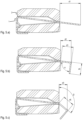
- Fig. 5.a shows the state after inserting a conductor element 1 of preliminary form into the housing 2.
- the bending edges on the left side, as well as the embossed protrusion may be prepared before the insertion step.
- both openings of the housing are sealed already.
- a flat part of the sheet metal forming the conductor element protrudes by a distance d1 out of the housing on the right side in the figure.
- Fig. 5.b shows the state after an additional bending step.
- the position of the further bending edge and the angle may be specified by the distances d2, d3, d4 and the angle ⁇ , see table below.
- Fig. 5.c shows an optional intermediate state after a further bending step and before bringing the second terminal into its final position on the bottom side of the housing.
- a further bending edge is produced in close proximity to the smaller opening of the housing on the right side in the present figure.
- the geometry is specified by the distances d5 and d6 as well as the angle ⁇ , see table below.
- the following distances and angles may be applied: d1 (mm) d2 (mm) d3 (mm) d4 (mm) d5 (mm) d6 (mm) ⁇ ⁇ 3.91 2.01 2.07 2.2 1.53 2.19 90° 130°
- Angle ⁇ may be deliberately made slightly smaller than a right angle, e.g. 0.5° to 3° smaller, such that a press-fit is achieved once the terminal part is in its final position on the lower side of the fuse.
Landscapes
- Fuses (AREA)
- Emergency Protection Circuit Devices (AREA)
Claims (12)
- Strombegrenzende Sicherung (20) umfassend- ein elektrisch isolierendes Gehäuse (2) mit Wänden, die einen Innenraum (6) umgeben, mit einer ersten Öffnung (7) und mit einer zweiten Öffnung (8), die der ersten Öffnung gegenüberliegt, und- ein einstückig ausgebildetes elektrisches Leiterelement (1), das sich von einem ersten Anschlussbereich (3) ausserhalb des Gehäuses, quer über die erste Öffnung, über den Innenraum, über die zweite Öffnung und zu einem zweiten Anschlussbereich (4) ausserhalb des Gehäuses erstreckt,wobei das Leiterelement einen Schmelzabschnitt (5) mit reduziertem Querschnitt aufweist, wobei der Schmelzabschnitt in dem Innenraum angeordnet ist und so konfiguriert ist, dass er schmilzt, wenn ein vordefinierter maximal zulässiger elektrischer Strom in dem Leiterelement überschritten wird, und wobei ein erster Dichtungsabschnitt (9) des Leiterelements die erste Öffnung (7) abdichtet und wobei ein zweiter Dichtungsabschnitt (10) des Leiterelements die zweite Öffnung (8) abdichtet,dadurch gekennzeichnet, dassder zweite Dichtungsabschnitt (10) des Leiterelements einen Vorsprung (11) aufweist, der in Richtung des Innenraums (6) vorsteht, wobei dieser Vorsprung an einem Konturabschnitt der zweiten Öffnung (8) abgestützt ist.
- Strombegrenzende Sicherung nach Anspruch 1, wobei das Leiterelement (1) ein Blech ist.
- Strombegrenzende Sicherung nach Anspruch 1 oder 2, wobei der erste Anschlussbereich (3) und der zweite Anschlussbereich (4) koplanar sind.
- Strombegrenzende Sicherung nach einem der Ansprüche 1 bis 3, wobei der Schmelzabschnitt (5) mechanisch selbsttragend über den Innenraum (6) ist.
- Strombegrenzende Sicherung nach einem der Ansprüche 1 bis 4, wobei der Querschnitt des ersten Dichtungsabschnitts (9) des Leiterelements in Form und Abmessung dem Querschnitt der ersten Öffnung (7) entspricht und/oder wobei der Querschnitt des zweiten Dichtungsabschnitts (10) des Leiterelements in Form und Abmessung dem Querschnitt der zweiten Öffnung (8) entspricht.
- Strombegrenzende Sicherung nach einem der Ansprüche 1 bis 5, wobei die Wände des Gehäuses (2), der erste Dichtungsabschnitt (9) des Leiterelements und der zweite Dichtungsabschnitt (10) des Leiterelements zusammen eine staubdichte Kapselung bilden.
- Strombegrenzende Sicherung nach einem der Ansprüche 1 bis 6, wobei der Querschnitt der zweiten Öffnung (8) grösser ist als der Querschnitt der ersten Öffnung (7).
- Strombegrenzende Sicherung nach einem der Ansprüche 1 bis 7, wobei mindestens eine dem Innenraum zugewandte Nut in das Gehäuse eingeformt ist, insbesondere wobei die Nut in eine Unterseite des Gehäuses ausgebildet ist, wobei die Unterseite an den ersten und den zweiten Anschlussbereich angrenzt.
- Strombegrenzende Sicherung nach einem der Ansprüche 1 bis 8, wobei die geometrische Form des Innenraums (6) definiert ist als das Negativ eines gedachten Kerns, der durch die zweite Öffnung (8) einstückig herausnehmbar ist.
- Strombegrenzende Sicherung nach einem der Ansprüche 1 bis 9, wobei das Gehäuse (2) einstückig ausgebildet ist.
- Strombegrenzende Sicherung nach einem der Ansprüche 1 bis 10, wobei die strombegrenzende Sicherung aus dem Gehäuse (2) und dem Leiterelement (1) besteht.
- Verfahren zur Herstellung einer strombegrenzenden Sicherung nach einem der Ansprüche 1 bis 11, wobei das Verfahren die folgenden Schritte umfasst:a) Bereitstellen (101) eines einstückig ausgebildeten elektrisch isolierenden Gehäuses (2) mit Wänden, die einen Innenraum (6) umgeben, mit einer ersten Öffnung (7) und mit einer zweiten Öffnung (8), die der ersten Öffnung gegenüberliegt,b) Bereitstellen (102) eines elektrisch leitenden, einstückig ausgebildeten Leiterelements (1) mit einem Schmelzabschnitt (5) mit reduziertem Querschnitt,c) Einführen (103) des Leiterelements (1) durch die erste Öffnung (7) oder durch die zweite Öffnung (8) soweit, dass sich der Schmelzabschnitt (5) im Innenraum (6) befindet,d) Biegen des Leiterelements um einen ersten Anschlussbereich (3) und einen zweiten Anschlussbereich (4) ausserhalb des Gehäuses zu bilden, wodurch die erste Öffnung (7) durch einen ersten Abschnitt (9) des Leiterelements abgedichtet wird und die zweite Öffnung (8) durch einen zweiten Abschnitt des Leiterelements abgedichtet wird,
dadurch gekennzeichnet,dass das in Schritt a) vorgesehene Leiterelement (1) ein Blech mit einem geprägten Vorsprung (11) ist, wobei das Blech eine erste Biegekante aufweist, die den ersten Anschlussbereich begrenzt, wobei das Blech eine zweite Biegekante aufweist, die von dem Vorsprung durch einen Abstand beabstandet ist, der einen festen Sitz der Biegekante und des Vorsprungs zwischen gegenüberliegenden Innenkonturen der zweiten Öffnung ermöglicht, wobei das Blech in dem Bereich zwischen der zweiten Biegekante und dem dem ersten Anschlussbereich gegenüberliegenden Ende flach ist,dass der Schritt c) des Einführens des Leiterelements das Zuführen des flachen Bereichs des Leiterelements aus dem Innenraum durch die erste Öffnung umfasst, unddass der Schritt d) das Festlegen einer dritten Biegekante, die den zweiten Anschlussbereich begrenzt, und dann das Festlegen einer vierten Biegekante in der Nähe der ersten Öffnung umfasst.
Applications Claiming Priority (1)
| Application Number | Priority Date | Filing Date | Title |
|---|---|---|---|
| PCT/EP2020/052356 WO2021151498A1 (en) | 2020-01-30 | 2020-01-30 | Current-limiting fuse |
Publications (2)
| Publication Number | Publication Date |
|---|---|
| EP4097750A1 EP4097750A1 (de) | 2022-12-07 |
| EP4097750B1 true EP4097750B1 (de) | 2024-06-05 |
Family
ID=69411448
Family Applications (1)
| Application Number | Title | Priority Date | Filing Date |
|---|---|---|---|
| EP20703014.9A Active EP4097750B1 (de) | 2020-01-30 | 2020-01-30 | Strombegrenzungssicherung |
Country Status (7)
| Country | Link |
|---|---|
| US (1) | US12431315B2 (de) |
| EP (1) | EP4097750B1 (de) |
| JP (1) | JP7500735B2 (de) |
| KR (1) | KR102804278B1 (de) |
| CN (1) | CN114868221B (de) |
| TW (1) | TWI874551B (de) |
| WO (1) | WO2021151498A1 (de) |
Families Citing this family (2)
| Publication number | Priority date | Publication date | Assignee | Title |
|---|---|---|---|---|
| KR20240072295A (ko) * | 2021-10-15 | 2024-05-23 | 슈르터 악티엔게젤샤프트 | 전기 퓨즈 |
| CN115621099A (zh) * | 2022-11-11 | 2023-01-17 | 南京萨特科技发展有限公司 | 一种芯片式熔断器及其制备方法 |
Family Cites Families (14)
| Publication number | Priority date | Publication date | Assignee | Title |
|---|---|---|---|---|
| US5229739A (en) * | 1992-02-21 | 1993-07-20 | Littelfuse, Inc. | Automotive high current fuse |
| US9378917B2 (en) * | 2012-02-20 | 2016-06-28 | Matsuo Electric Co., Ltd. | Chip-type fuse |
| JP2014154284A (ja) * | 2013-02-06 | 2014-08-25 | Yazaki Corp | ヒューズ及びヒューズの作製方法 |
| JP6437239B2 (ja) * | 2013-08-28 | 2018-12-12 | デクセリアルズ株式会社 | ヒューズエレメント、ヒューズ素子 |
| JP6214318B2 (ja) * | 2013-10-09 | 2017-10-18 | デクセリアルズ株式会社 | 電流ヒューズ |
| US10141150B2 (en) * | 2016-02-17 | 2018-11-27 | Littelfuse, Inc. | High current one-piece fuse element and split body |
| EP3217417A1 (de) * | 2016-03-07 | 2017-09-13 | Siemens Aktiengesellschaft | Unterwassersicherung |
| JP7002955B2 (ja) * | 2017-02-28 | 2022-01-20 | デクセリアルズ株式会社 | ヒューズ素子 |
| JP2019036509A (ja) * | 2017-08-22 | 2019-03-07 | 太平洋精工株式会社 | 多連型ヒューズ、及び当該多連型ヒューズを用いたバッテリーの充電方法 |
| JP7010706B2 (ja) * | 2018-01-10 | 2022-01-26 | デクセリアルズ株式会社 | ヒューズ素子 |
| JP7256667B2 (ja) * | 2019-03-28 | 2023-04-12 | デクセリアルズ株式会社 | 保護素子 |
| DE102019005664A1 (de) * | 2019-06-25 | 2020-12-31 | Siba Fuses Gmbh | Schmelzleiter sowie Sicherung |
| US11270861B1 (en) * | 2020-09-30 | 2022-03-08 | Littelfuse, Inc. | Protection device including radial lead fuse |
| KR20240072295A (ko) * | 2021-10-15 | 2024-05-23 | 슈르터 악티엔게젤샤프트 | 전기 퓨즈 |
-
2020
- 2020-01-30 EP EP20703014.9A patent/EP4097750B1/de active Active
- 2020-01-30 JP JP2022542182A patent/JP7500735B2/ja active Active
- 2020-01-30 US US17/796,395 patent/US12431315B2/en active Active
- 2020-01-30 WO PCT/EP2020/052356 patent/WO2021151498A1/en not_active Ceased
- 2020-01-30 KR KR1020227029083A patent/KR102804278B1/ko active Active
- 2020-01-30 CN CN202080090623.6A patent/CN114868221B/zh active Active
-
2021
- 2021-01-07 TW TW110100591A patent/TWI874551B/zh active
Also Published As
| Publication number | Publication date |
|---|---|
| KR102804278B1 (ko) | 2025-05-08 |
| TWI874551B (zh) | 2025-03-01 |
| WO2021151498A1 (en) | 2021-08-05 |
| JP2023512162A (ja) | 2023-03-24 |
| EP4097750A1 (de) | 2022-12-07 |
| US12431315B2 (en) | 2025-09-30 |
| TW202133207A (zh) | 2021-09-01 |
| CN114868221A (zh) | 2022-08-05 |
| JP7500735B2 (ja) | 2024-06-17 |
| CN114868221B (zh) | 2026-03-31 |
| KR20220127928A (ko) | 2022-09-20 |
| US20230343540A1 (en) | 2023-10-26 |
Similar Documents
| Publication | Publication Date | Title |
|---|---|---|
| US6888440B2 (en) | Fuse with fuse link coating | |
| CN105518820B (zh) | 熔丝元件及熔丝单元 | |
| JP3820143B2 (ja) | 表面実装型小型ヒューズ | |
| JP5026914B2 (ja) | ヒューズエレメント及びこのヒューズエレメントを用いてなるヒュージブルリンク | |
| WO2015052923A1 (ja) | 電流ヒューズ | |
| CN101401181B (zh) | 表面安装型电流熔断器 | |
| US7473487B2 (en) | Temperature fuse, and battery using the same | |
| JP6694303B2 (ja) | 面実装型抵抗器 | |
| EP4097750B1 (de) | Strombegrenzungssicherung | |
| KR940008191B1 (ko) | 고차단 초소형 퓨즈 | |
| JP6491431B2 (ja) | ヒューズ素子、及びヒューズエレメント | |
| EP4416751B1 (de) | Elektrische sicherung und verfahren zur herstellung | |
| KR20180107234A (ko) | 보호 소자 | |
| JP4896630B2 (ja) | ヒューズエレメント及びヒューズエレメントの製造方法 | |
| JP2005235680A (ja) | チップ型ヒューズおよびその製造方法 | |
| KR102080041B1 (ko) | 제조공정이 용이한 엘레먼트를 구비한 퓨즈 | |
| KR101742215B1 (ko) | 소형 퓨즈 제작 방법 |
Legal Events
| Date | Code | Title | Description |
|---|---|---|---|
| STAA | Information on the status of an ep patent application or granted ep patent |
Free format text: STATUS: UNKNOWN |
|
| STAA | Information on the status of an ep patent application or granted ep patent |
Free format text: STATUS: THE INTERNATIONAL PUBLICATION HAS BEEN MADE |
|
| PUAI | Public reference made under article 153(3) epc to a published international application that has entered the european phase |
Free format text: ORIGINAL CODE: 0009012 |
|
| STAA | Information on the status of an ep patent application or granted ep patent |
Free format text: STATUS: REQUEST FOR EXAMINATION WAS MADE |
|
| 17P | Request for examination filed |
Effective date: 20220706 |
|
| AK | Designated contracting states |
Kind code of ref document: A1 Designated state(s): AL AT BE BG CH CY CZ DE DK EE ES FI FR GB GR HR HU IE IS IT LI LT LU LV MC MK MT NL NO PL PT RO RS SE SI SK SM TR |
|
| DAV | Request for validation of the european patent (deleted) | ||
| DAX | Request for extension of the european patent (deleted) | ||
| P01 | Opt-out of the competence of the unified patent court (upc) registered |
Effective date: 20230514 |
|
| GRAP | Despatch of communication of intention to grant a patent |
Free format text: ORIGINAL CODE: EPIDOSNIGR1 |
|
| STAA | Information on the status of an ep patent application or granted ep patent |
Free format text: STATUS: GRANT OF PATENT IS INTENDED |
|
| INTG | Intention to grant announced |
Effective date: 20240124 |
|
| GRAS | Grant fee paid |
Free format text: ORIGINAL CODE: EPIDOSNIGR3 |
|
| GRAA | (expected) grant |
Free format text: ORIGINAL CODE: 0009210 |
|
| STAA | Information on the status of an ep patent application or granted ep patent |
Free format text: STATUS: THE PATENT HAS BEEN GRANTED |
|
| RIN1 | Information on inventor provided before grant (corrected) |
Inventor name: SIGNER, GUIDO Inventor name: SCHIBLI, BENJAMIN |
|
| AK | Designated contracting states |
Kind code of ref document: B1 Designated state(s): AL AT BE BG CH CY CZ DE DK EE ES FI FR GB GR HR HU IE IS IT LI LT LU LV MC MK MT NL NO PL PT RO RS SE SI SK SM TR |
|
| REG | Reference to a national code |
Ref country code: CH Ref legal event code: EP |
|
| REG | Reference to a national code |
Ref country code: DE Ref legal event code: R096 Ref document number: 602020031929 Country of ref document: DE |
|
| REG | Reference to a national code |
Ref country code: IE Ref legal event code: FG4D |
|
| REG | Reference to a national code |
Ref country code: LT Ref legal event code: MG9D |
|
| PG25 | Lapsed in a contracting state [announced via postgrant information from national office to epo] |
Ref country code: BG Free format text: LAPSE BECAUSE OF FAILURE TO SUBMIT A TRANSLATION OF THE DESCRIPTION OR TO PAY THE FEE WITHIN THE PRESCRIBED TIME-LIMIT Effective date: 20240605 |
|
| REG | Reference to a national code |
Ref country code: NL Ref legal event code: MP Effective date: 20240605 |
|
| PG25 | Lapsed in a contracting state [announced via postgrant information from national office to epo] |
Ref country code: FI Free format text: LAPSE BECAUSE OF FAILURE TO SUBMIT A TRANSLATION OF THE DESCRIPTION OR TO PAY THE FEE WITHIN THE PRESCRIBED TIME-LIMIT Effective date: 20240605 Ref country code: HR Free format text: LAPSE BECAUSE OF FAILURE TO SUBMIT A TRANSLATION OF THE DESCRIPTION OR TO PAY THE FEE WITHIN THE PRESCRIBED TIME-LIMIT Effective date: 20240605 |
|
| PG25 | Lapsed in a contracting state [announced via postgrant information from national office to epo] |
Ref country code: GR Free format text: LAPSE BECAUSE OF FAILURE TO SUBMIT A TRANSLATION OF THE DESCRIPTION OR TO PAY THE FEE WITHIN THE PRESCRIBED TIME-LIMIT Effective date: 20240906 |
|
| PG25 | Lapsed in a contracting state [announced via postgrant information from national office to epo] |
Ref country code: ES Free format text: LAPSE BECAUSE OF FAILURE TO SUBMIT A TRANSLATION OF THE DESCRIPTION OR TO PAY THE FEE WITHIN THE PRESCRIBED TIME-LIMIT Effective date: 20240605 |
|
| PG25 | Lapsed in a contracting state [announced via postgrant information from national office to epo] |
Ref country code: LV Free format text: LAPSE BECAUSE OF FAILURE TO SUBMIT A TRANSLATION OF THE DESCRIPTION OR TO PAY THE FEE WITHIN THE PRESCRIBED TIME-LIMIT Effective date: 20240605 |
|
| PG25 | Lapsed in a contracting state [announced via postgrant information from national office to epo] |
Ref country code: NO Free format text: LAPSE BECAUSE OF FAILURE TO SUBMIT A TRANSLATION OF THE DESCRIPTION OR TO PAY THE FEE WITHIN THE PRESCRIBED TIME-LIMIT Effective date: 20240905 Ref country code: LV Free format text: LAPSE BECAUSE OF FAILURE TO SUBMIT A TRANSLATION OF THE DESCRIPTION OR TO PAY THE FEE WITHIN THE PRESCRIBED TIME-LIMIT Effective date: 20240605 Ref country code: HR Free format text: LAPSE BECAUSE OF FAILURE TO SUBMIT A TRANSLATION OF THE DESCRIPTION OR TO PAY THE FEE WITHIN THE PRESCRIBED TIME-LIMIT Effective date: 20240605 Ref country code: GR Free format text: LAPSE BECAUSE OF FAILURE TO SUBMIT A TRANSLATION OF THE DESCRIPTION OR TO PAY THE FEE WITHIN THE PRESCRIBED TIME-LIMIT Effective date: 20240906 Ref country code: FI Free format text: LAPSE BECAUSE OF FAILURE TO SUBMIT A TRANSLATION OF THE DESCRIPTION OR TO PAY THE FEE WITHIN THE PRESCRIBED TIME-LIMIT Effective date: 20240605 Ref country code: ES Free format text: LAPSE BECAUSE OF FAILURE TO SUBMIT A TRANSLATION OF THE DESCRIPTION OR TO PAY THE FEE WITHIN THE PRESCRIBED TIME-LIMIT Effective date: 20240605 Ref country code: BG Free format text: LAPSE BECAUSE OF FAILURE TO SUBMIT A TRANSLATION OF THE DESCRIPTION OR TO PAY THE FEE WITHIN THE PRESCRIBED TIME-LIMIT Effective date: 20240605 Ref country code: RS Free format text: LAPSE BECAUSE OF FAILURE TO SUBMIT A TRANSLATION OF THE DESCRIPTION OR TO PAY THE FEE WITHIN THE PRESCRIBED TIME-LIMIT Effective date: 20240905 |
|
| PG25 | Lapsed in a contracting state [announced via postgrant information from national office to epo] |
Ref country code: NL Free format text: LAPSE BECAUSE OF FAILURE TO SUBMIT A TRANSLATION OF THE DESCRIPTION OR TO PAY THE FEE WITHIN THE PRESCRIBED TIME-LIMIT Effective date: 20240605 |
|
| REG | Reference to a national code |
Ref country code: AT Ref legal event code: MK05 Ref document number: 1693086 Country of ref document: AT Kind code of ref document: T Effective date: 20240605 |
|
| PG25 | Lapsed in a contracting state [announced via postgrant information from national office to epo] |
Ref country code: NL Free format text: LAPSE BECAUSE OF FAILURE TO SUBMIT A TRANSLATION OF THE DESCRIPTION OR TO PAY THE FEE WITHIN THE PRESCRIBED TIME-LIMIT Effective date: 20240605 |
|
| PG25 | Lapsed in a contracting state [announced via postgrant information from national office to epo] |
Ref country code: PT Free format text: LAPSE BECAUSE OF FAILURE TO SUBMIT A TRANSLATION OF THE DESCRIPTION OR TO PAY THE FEE WITHIN THE PRESCRIBED TIME-LIMIT Effective date: 20241007 |
|
| PG25 | Lapsed in a contracting state [announced via postgrant information from national office to epo] |
Ref country code: PT Free format text: LAPSE BECAUSE OF FAILURE TO SUBMIT A TRANSLATION OF THE DESCRIPTION OR TO PAY THE FEE WITHIN THE PRESCRIBED TIME-LIMIT Effective date: 20241007 |
|
| PG25 | Lapsed in a contracting state [announced via postgrant information from national office to epo] |
Ref country code: PL Free format text: LAPSE BECAUSE OF FAILURE TO SUBMIT A TRANSLATION OF THE DESCRIPTION OR TO PAY THE FEE WITHIN THE PRESCRIBED TIME-LIMIT Effective date: 20240605 |
|
| PG25 | Lapsed in a contracting state [announced via postgrant information from national office to epo] |
Ref country code: EE Free format text: LAPSE BECAUSE OF FAILURE TO SUBMIT A TRANSLATION OF THE DESCRIPTION OR TO PAY THE FEE WITHIN THE PRESCRIBED TIME-LIMIT Effective date: 20240605 |
|
| PG25 | Lapsed in a contracting state [announced via postgrant information from national office to epo] |
Ref country code: AT Free format text: LAPSE BECAUSE OF FAILURE TO SUBMIT A TRANSLATION OF THE DESCRIPTION OR TO PAY THE FEE WITHIN THE PRESCRIBED TIME-LIMIT Effective date: 20240605 Ref country code: IS Free format text: LAPSE BECAUSE OF FAILURE TO SUBMIT A TRANSLATION OF THE DESCRIPTION OR TO PAY THE FEE WITHIN THE PRESCRIBED TIME-LIMIT Effective date: 20241005 |
|
| PG25 | Lapsed in a contracting state [announced via postgrant information from national office to epo] |
Ref country code: CZ Free format text: LAPSE BECAUSE OF FAILURE TO SUBMIT A TRANSLATION OF THE DESCRIPTION OR TO PAY THE FEE WITHIN THE PRESCRIBED TIME-LIMIT Effective date: 20240605 |
|
| PG25 | Lapsed in a contracting state [announced via postgrant information from national office to epo] |
Ref country code: RO Free format text: LAPSE BECAUSE OF FAILURE TO SUBMIT A TRANSLATION OF THE DESCRIPTION OR TO PAY THE FEE WITHIN THE PRESCRIBED TIME-LIMIT Effective date: 20240605 Ref country code: SK Free format text: LAPSE BECAUSE OF FAILURE TO SUBMIT A TRANSLATION OF THE DESCRIPTION OR TO PAY THE FEE WITHIN THE PRESCRIBED TIME-LIMIT Effective date: 20240605 |
|
| PG25 | Lapsed in a contracting state [announced via postgrant information from national office to epo] |
Ref country code: SM Free format text: LAPSE BECAUSE OF FAILURE TO SUBMIT A TRANSLATION OF THE DESCRIPTION OR TO PAY THE FEE WITHIN THE PRESCRIBED TIME-LIMIT Effective date: 20240605 |
|
| PG25 | Lapsed in a contracting state [announced via postgrant information from national office to epo] |
Ref country code: SM Free format text: LAPSE BECAUSE OF FAILURE TO SUBMIT A TRANSLATION OF THE DESCRIPTION OR TO PAY THE FEE WITHIN THE PRESCRIBED TIME-LIMIT Effective date: 20240605 Ref country code: SK Free format text: LAPSE BECAUSE OF FAILURE TO SUBMIT A TRANSLATION OF THE DESCRIPTION OR TO PAY THE FEE WITHIN THE PRESCRIBED TIME-LIMIT Effective date: 20240605 Ref country code: RO Free format text: LAPSE BECAUSE OF FAILURE TO SUBMIT A TRANSLATION OF THE DESCRIPTION OR TO PAY THE FEE WITHIN THE PRESCRIBED TIME-LIMIT Effective date: 20240605 Ref country code: PL Free format text: LAPSE BECAUSE OF FAILURE TO SUBMIT A TRANSLATION OF THE DESCRIPTION OR TO PAY THE FEE WITHIN THE PRESCRIBED TIME-LIMIT Effective date: 20240605 Ref country code: IS Free format text: LAPSE BECAUSE OF FAILURE TO SUBMIT A TRANSLATION OF THE DESCRIPTION OR TO PAY THE FEE WITHIN THE PRESCRIBED TIME-LIMIT Effective date: 20241005 Ref country code: EE Free format text: LAPSE BECAUSE OF FAILURE TO SUBMIT A TRANSLATION OF THE DESCRIPTION OR TO PAY THE FEE WITHIN THE PRESCRIBED TIME-LIMIT Effective date: 20240605 Ref country code: CZ Free format text: LAPSE BECAUSE OF FAILURE TO SUBMIT A TRANSLATION OF THE DESCRIPTION OR TO PAY THE FEE WITHIN THE PRESCRIBED TIME-LIMIT Effective date: 20240605 Ref country code: AT Free format text: LAPSE BECAUSE OF FAILURE TO SUBMIT A TRANSLATION OF THE DESCRIPTION OR TO PAY THE FEE WITHIN THE PRESCRIBED TIME-LIMIT Effective date: 20240605 |
|
| PG25 | Lapsed in a contracting state [announced via postgrant information from national office to epo] |
Ref country code: IT Free format text: LAPSE BECAUSE OF FAILURE TO SUBMIT A TRANSLATION OF THE DESCRIPTION OR TO PAY THE FEE WITHIN THE PRESCRIBED TIME-LIMIT Effective date: 20240605 |
|
| REG | Reference to a national code |
Ref country code: DE Ref legal event code: R097 Ref document number: 602020031929 Country of ref document: DE |
|
| PLBE | No opposition filed within time limit |
Free format text: ORIGINAL CODE: 0009261 |
|
| STAA | Information on the status of an ep patent application or granted ep patent |
Free format text: STATUS: NO OPPOSITION FILED WITHIN TIME LIMIT |
|
| PG25 | Lapsed in a contracting state [announced via postgrant information from national office to epo] |
Ref country code: DK Free format text: LAPSE BECAUSE OF FAILURE TO SUBMIT A TRANSLATION OF THE DESCRIPTION OR TO PAY THE FEE WITHIN THE PRESCRIBED TIME-LIMIT Effective date: 20240605 |
|
| 26N | No opposition filed |
Effective date: 20250306 |
|
| PG25 | Lapsed in a contracting state [announced via postgrant information from national office to epo] |
Ref country code: SE Free format text: LAPSE BECAUSE OF FAILURE TO SUBMIT A TRANSLATION OF THE DESCRIPTION OR TO PAY THE FEE WITHIN THE PRESCRIBED TIME-LIMIT Effective date: 20240605 |
|
| PG25 | Lapsed in a contracting state [announced via postgrant information from national office to epo] |
Ref country code: LU Free format text: LAPSE BECAUSE OF NON-PAYMENT OF DUE FEES Effective date: 20250130 Ref country code: MC Free format text: LAPSE BECAUSE OF FAILURE TO SUBMIT A TRANSLATION OF THE DESCRIPTION OR TO PAY THE FEE WITHIN THE PRESCRIBED TIME-LIMIT Effective date: 20240605 |
|
| PG25 | Lapsed in a contracting state [announced via postgrant information from national office to epo] |
Ref country code: BE Free format text: LAPSE BECAUSE OF NON-PAYMENT OF DUE FEES Effective date: 20250131 |
|
| REG | Reference to a national code |
Ref country code: BE Ref legal event code: MM Effective date: 20250131 |
|
| PGFP | Annual fee paid to national office [announced via postgrant information from national office to epo] |
Ref country code: GB Payment date: 20251211 Year of fee payment: 7 |
|
| PGFP | Annual fee paid to national office [announced via postgrant information from national office to epo] |
Ref country code: FR Payment date: 20251208 Year of fee payment: 7 |
|
| PG25 | Lapsed in a contracting state [announced via postgrant information from national office to epo] |
Ref country code: IE Free format text: LAPSE BECAUSE OF NON-PAYMENT OF DUE FEES Effective date: 20250130 |
|
| REG | Reference to a national code |
Ref country code: CH Ref legal event code: U11 Free format text: ST27 STATUS EVENT CODE: U-0-0-U10-U11 (AS PROVIDED BY THE NATIONAL OFFICE) Effective date: 20260201 |
|
| PGFP | Annual fee paid to national office [announced via postgrant information from national office to epo] |
Ref country code: DE Payment date: 20251210 Year of fee payment: 7 |
|
| PGFP | Annual fee paid to national office [announced via postgrant information from national office to epo] |
Ref country code: CH Payment date: 20260201 Year of fee payment: 7 |