EP4097372B1 - Zweimassenschwungrad mit lösbarem drehmomentbegrenzer - Google Patents
Zweimassenschwungrad mit lösbarem drehmomentbegrenzer Download PDFInfo
- Publication number
- EP4097372B1 EP4097372B1 EP21701645.0A EP21701645A EP4097372B1 EP 4097372 B1 EP4097372 B1 EP 4097372B1 EP 21701645 A EP21701645 A EP 21701645A EP 4097372 B1 EP4097372 B1 EP 4097372B1
- Authority
- EP
- European Patent Office
- Prior art keywords
- output hub
- dual
- mass flywheel
- counter
- mass
- Prior art date
- Legal status (The legal status is an assumption and is not a legal conclusion. Google has not performed a legal analysis and makes no representation as to the accuracy of the status listed.)
- Active
Links
Images

Classifications
-
- F—MECHANICAL ENGINEERING; LIGHTING; HEATING; WEAPONS; BLASTING
- F16—ENGINEERING ELEMENTS AND UNITS; GENERAL MEASURES FOR PRODUCING AND MAINTAINING EFFECTIVE FUNCTIONING OF MACHINES OR INSTALLATIONS; THERMAL INSULATION IN GENERAL
- F16F—SPRINGS; SHOCK-ABSORBERS; MEANS FOR DAMPING VIBRATION
- F16F15/00—Suppression of vibrations in systems; Means or arrangements for avoiding or reducing out-of-balance forces, e.g. due to motion
- F16F15/10—Suppression of vibrations in rotating systems by making use of members moving with the system
- F16F15/12—Suppression of vibrations in rotating systems by making use of members moving with the system using elastic members or friction-damping members, e.g. between a rotating shaft and a gyratory mass mounted thereon
- F16F15/131—Suppression of vibrations in rotating systems by making use of members moving with the system using elastic members or friction-damping members, e.g. between a rotating shaft and a gyratory mass mounted thereon the rotating system comprising two or more gyratory masses
- F16F15/139—Suppression of vibrations in rotating systems by making use of members moving with the system using elastic members or friction-damping members, e.g. between a rotating shaft and a gyratory mass mounted thereon the rotating system comprising two or more gyratory masses characterised by friction-damping means
- F16F15/1397—Overload protection, i.e. means for limiting torque
-
- F—MECHANICAL ENGINEERING; LIGHTING; HEATING; WEAPONS; BLASTING
- F16—ENGINEERING ELEMENTS AND UNITS; GENERAL MEASURES FOR PRODUCING AND MAINTAINING EFFECTIVE FUNCTIONING OF MACHINES OR INSTALLATIONS; THERMAL INSULATION IN GENERAL
- F16F—SPRINGS; SHOCK-ABSORBERS; MEANS FOR DAMPING VIBRATION
- F16F15/00—Suppression of vibrations in systems; Means or arrangements for avoiding or reducing out-of-balance forces, e.g. due to motion
- F16F15/10—Suppression of vibrations in rotating systems by making use of members moving with the system
- F16F15/12—Suppression of vibrations in rotating systems by making use of members moving with the system using elastic members or friction-damping members, e.g. between a rotating shaft and a gyratory mass mounted thereon
- F16F15/131—Suppression of vibrations in rotating systems by making use of members moving with the system using elastic members or friction-damping members, e.g. between a rotating shaft and a gyratory mass mounted thereon the rotating system comprising two or more gyratory masses
- F16F15/13142—Suppression of vibrations in rotating systems by making use of members moving with the system using elastic members or friction-damping members, e.g. between a rotating shaft and a gyratory mass mounted thereon the rotating system comprising two or more gyratory masses characterised by the method of assembly, production or treatment
Definitions
- the invention relates to a dual-mass flywheel with a primary side and a secondary side, which can be rotated relative to one another against a restoring torque of an energy store, comprising a secondary-side torque limiter, comprising two counter-disks riveted to one another, which are in frictional contact with a secondary flange, and an output hub which is coupled to the counter-disks for transmitting a torque.
- Dual-mass flywheels are used to dampen vibrations in the drivetrain of motor vehicles between an internal combustion engine and a vehicle clutch.
- a friction device on the secondary side serves as a torque limiter (TLM).
- a torsional vibration damper is disclosed, the primary input part of which is screwed directly to a crankshaft and a slip clutch is arranged between the primary part and the secondary part.
- a dual-mass flywheel of this type originates from the DE 10 2016 204261 A1 This reveals a dual-mass flywheel with a primary side and a secondary side. The primary side and the secondary side can be rotated relative to each other against a restoring torque of an energy storage device.
- a slip clutch serves as a secondary-side torque limiter. Two counter plates are riveted together with a secondary mass and are in contact with the secondary flange to form the slip clutch. Friction connection.
- an output hub is coupled to the secondary mass via a toothed system and to the counter plates via a riveted connection.
- the primary mass has a primary mass plate, which can be connected to the crankshaft on the engine side using crankshaft bolts via holes in the primary mass plate.
- the output hub has holes through which the crankshaft bolts are accessible when the dual-mass flywheel is installed.
- a disc spring is axially clamped between the output hub and one of the counter plates, which applies a pressure force to the disc spring axially against a stop formed by the secondary mass.
- One object of the invention is to provide a simple and cost-effective measure which, in the event of an angular misalignment between the bores of the output hub and the screw connections of the dual-mass flywheel on the crankshaft, allows the output flange to be rotated by loosening the clutch until the bores are aligned with the heads of the screws.
- the invention provides a dual-mass flywheel with a primary side and a secondary side, which are rotatable relative to each other against a restoring torque of an energy storage device, comprising a secondary-side torque limiter, comprising two counter-disks riveted to each other, which are in frictional contact with a secondary flange, and an output hub coupled to the counter discs for transmitting torque.
- the output hub has a toothing that engages with a toothing of one of the counter discs, with the output hub being axially loaded by a disc spring with a pressure force acting against a stop in the direction of the primary side.
- the disc spring rests on a retaining plate attached to the counter discs.
- the retaining plate is preferably riveted to the counter discs. Riveting of the counter discs is preferred for this purpose.
- the retaining plate prevents deformation of the disc spring during assembly of the rivets that connect the counter disc and the retaining plate. Without the retaining plate, the disc springs would have to rest directly on the rivet heads, and the riveting would have to be carried out in the presence of the disc spring. Unintentional deformation of the disc spring can change the slipping torque of the torque limiter or even lead to premature failure due to breakage of the disc spring or similar.
- the retaining plate comprises a mounting ring and a support ring arranged axially offset from the mounting ring.
- the outer circumference of the disc spring preferably rests on the support ring and its inner circumference rests on a shoulder of the output hub. This defines the radial position of the disc spring and simultaneously contributes to the centering of the assemblies.
- the inner diameter of the friction disc facing the primary mass plate is preferably smaller, at least in some areas, than the outer diameter of the gearing of an output hub.
- the friction disc thus forms an axial stop for the output hub.
- the output hub has holes through which the crankshaft bolts are accessible when the dual-mass flywheel is installed.
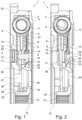
- the Figures 1 and 2 show a dual-mass flywheel according to the invention in sectional views in two radial planes.
- the dual-mass flywheel 1 comprises a primary mass or primary side 2 and a secondary mass or secondary side 3, which can be rotated relative to each other about the rotational axis R against the force of a bow spring 4.
- the rotational axis of the dual-mass flywheel is in Fig. 1 denoted by R.
- the axial direction is understood to be the direction parallel to the rotation axis R
- the radial direction is understood to be a direction perpendicular to the rotation axis R
- the circumferential direction is understood to be a rotation about the rotation axis R.
- the primary mass 2 comprises an engine-side primary mass plate 6 and a clutch-side primary mass cover 5.
- the primary mass plate 6 and the primary mass cover 5 enclose a bow spring receptacle 7 in which the bow spring 4, or possibly several bow springs 4, is or are arranged.
- the arc spring 4 is supported with one spring end on the primary mass 2, for example on lugs (not shown here) that protrude into the arc spring receptacle 7 enclosed by the primary mass plate 6 and the primary mass cover 5.
- the other spring end of the arc spring 4 is supported on flange wings of a secondary flange 8.
- the flange wings extend radially outward and enclose the spring ends of the arc springs 4.
- the primary mass plate 6 can be connected to a crankshaft by means of crankshaft screws (not shown) via bores 10.
- a sliding shell 11 is arranged on the outer circumference of the arc spring 4 on the primary mass plate 6.
- the secondary flange 8 forms a slip clutch 14 with two counter discs, a left counter disc 12 and a right counter disc 13.
- the counter discs 12, 13 are riveted together with a disc spring membrane 9 and a retaining plate 15 by means of rivets 16.
- the slip clutch 14 serves as a torque limiter. If a slip torque MR defined by the static friction between the counter discs 12, 13 and the secondary flange 8 is exceeded, the slip clutch 14 slips and thus limits the transmitted torque MMax.
- the rivets are, as shown in Figure 3 As can be seen, they are arranged around the circumference and firmly connect the riveted parts together.
- the right counter-disk 13 has a toothing 17 on its inner circumference, into which a corresponding toothing 19 of an output hub 18 engages.
- This has bores 20 through which the crankshaft screw connection is accessible, as well as a plug-in toothing 21 for connecting the secondary side 3 to downstream components in the drive train.
- the retaining plate has a mounting ring 22 and a support ring 23, which are connected by an axially extending cylindrical part 24, which, as in Figure 3 can also be seen as individual webs, are connected to each other.
- a disc spring 25 is arranged between the support ring 23 and the output hub 18. Its outer circumference is centered on the cylindrical part 24 of the retaining plate, and its inner circumference is centered on a shoulder 26 of the output hub 18.
- the left counter disc 12 has an inner circumference that is smaller than the outer circumference of the toothing 19 of the output hub 18. This forms an axial stop for the output hub 18 in the direction of the primary mass plate 6.
- the outer region of the diaphragm spring 9 is in sliding contact near the outer circumference with a diaphragm ring 27 arranged on the primary mass cover 5.
- a disk 28 with a collar 29 is fastened to the primary mass plate 6 by the crankshaft screw connection.
- a friction ring 30 is clamped between the collar 29 and the output hub 18 and creates additional friction during a relative rotation of the primary side 2 with respect to the secondary side 3.
- Grease caps 31 cover mounting holes 32 in the primary mass plate 6, through which the rivets 16 are accessible during assembly of the dual-mass flywheel 1.
- a starter ring gear 33 is arranged on the outer circumference of the primary mass plate 6.
Landscapes
- Engineering & Computer Science (AREA)
- General Engineering & Computer Science (AREA)
- Physics & Mathematics (AREA)
- Acoustics & Sound (AREA)
- Aviation & Aerospace Engineering (AREA)
- Mechanical Engineering (AREA)
- Manufacturing & Machinery (AREA)
- Mechanical Operated Clutches (AREA)
Description
- Die Erfindung betrifft ein Zweimassenschwungrad mit einer Primärseite und einer Sekundärseite, die gegen ein Rückstellmoment eines Energiespeichers relativ zueinander verdrehbar sind, umfassend einen sekundärseitigen Drehmomentbegrenzer, umfassend zwei miteinander vernietete Gegenscheiben, die mit einem Sekundärflansch in Reibkontakt sind, sowie eine Abtriebsnabe, die mit den Gegenscheiben zur Übertragung eines Drehmomentes gekoppelt ist.
- Zweimassenschwungräder (ZMS) werden zur Schwingungstilgung im Antriebsstrang von Kraftfahrzeugen zwischen einem Verbrennungsmotor und einer Fahrzeugkupplung verwendet. Bei einem gattungsgemäßen Zweimassenschwungrad dient eine Reibeinrichtung auf der Sekundärseite als Drehmomentbegrenzer (DMB).
- Aus der
DE 10 2016 207708 A1 ist ein Torsionsschwingungsdämpfer offenbart, dessen primärseitiges Eingangsteil direkt mit einer Kurbelwelle verschraubt wird und zwischen dessen Primärteil und Sekundärteil eine Rutschkupplung angeordnet ist. - Ein Zweimassenschwungrad der Gattung geht aus der
DE 10 2016 204261 A1 hervor. Diese offenbart ein Zweimassenschwungrad eine Zweimassenschwungrad mit einer Primärseite und einer Sekundärseite. Die Primärseite und die Sekundärseite sind gegen ein Rückstellmoment eines Energiespeichers relativ zueinander verdrehbar. Als sekundärseitiger Drehmomentbegrenzer dient eine Rutschkupplung. Zwei Gegenscheiben sind zusammen mit einer Sekundärmasse miteinander vernietet und stehen mit dem Sekundärflansch zur Bildung der Rutschkupplung in einer Reibverbindung. Eine Abtriebsnabe ist zur Übertragung eines Drehmomentes über eine Verzahnung mit der Sekundärmasse und über deren Nietverbindung mit den Gegenscheiben gekoppelt. Die Primärmasse weist ein Primärmasseblech auf, welches motorseitig mittels Kurbelwellenschrauben über Bohrungen im Primärmasseblech mit der Kurbelwelle verbindbar. Die Abtriebsnabe weist Bohrungen auf, durch welche die Kurbelwellenschrauben in einer Einbausituation des Zweimassenschwungrades zugänglich sind. Zwischen der Abtriebsnabe und einer der Gegenscheiben ist eine Tellerfeder axial eingespannt, durch welche die Tellerfeder axial mit einer Andruckkraft gegen einen durch die Sekundärmasse gebildeten Anschlag beaufschlagt ist. - Eine Aufgabe der Erfindung ist es, eine einfache und kostengünstige Maßnahme zu schaffen, mit der im Falle eines Winkelversatzes zwischen den Bohrungen der Abtriebsnabe gegenüber den Verschraubungen des Zweimassenschwungrades an der Kurbelwelle durch Lösen der Kupplung ein Verdrehen des Abtriebsflansches bis zum Fluchten der Bohrungen zu den Köpfen der Schrauben ermöglicht werden kann..
- Die Augabe wird durch ein Zweimassenschwungrad nach Anspruch 1 und ein Verfahren nach Anspruch 8 gelöst. Bevorzugte Ausführungsformen, Ausgestaltungen oder Weiterbildungen der Erfindung sind in den abhängigen Ansprüchen angegeben.
- Die Erfindung sieht ein Zweimassenschwungrad mit einer Primärseite und einer Sekundärseite vor, die gegen ein Rückstellmoment eines Energiespeichers relativ zueinander verdrehbar sind, umfassend einen sekundärseitigen Drehmomentbegrenzer, umfassend zwei miteinander vernietete Gegenscheiben, die mit einem Sekundärflansch in Reibkontakt sind, sowie eine Abtriebsnabe, die mit den Gegenscheiben zur Übertragung eines Drehmomentes gekoppelt ist. Die Abtriebsnabe weist eine Verzahnung auf, die im Eingriff mit einer Verzahnung einer der Gegenscheiben ist, wobei die Abtriebsnabe durch eine Tellerfeder axial mit einer gegen einen Anschlag in Richtung auf die Primärseite wirkenden Andruckkraft beaufschlagt ist.
- Die Tellerfeder stützt sich an einem Halteblech ab, das an den Gegenscheiben befestigt ist. Das Halteblech ist mit den Gegenscheiben vorzugsweise vernietet. Dazu wird vorzugsweise die Vernietung der Gegenscheiben verwendet. Das Halteblech verhindert eine Verformung der Tellerfeder bei der Montage der Nieten, mit denen die Gegenscheibe und das Halteblech miteinander verbunden werden. Ohne das Halteblech müssten sich die Tellerfeder direkt an Nietköpfen der Niete abstützen, wobei die Vernietung in Anwesenheit der Tellerfeder hergestellt werden muss. Eine ungewollte Verformung der Tellerfeder kann das Rutschmoment des Drehmomentbegrenzers verändern oder gar zu einem vorzeitigen Ausfall durch einen Bruch der Tellerfeder oder dergleichen führen.
- Das Halteblech umfasst einen Montagering und einen axial diesem gegenüber versetzt angeordneten Stützring, wobei sich die Tellerfeder mit ihrem Außenumfang vorzugsweise an dem Stützring abstützt und mit ihrem Innenumfang an einem Absatz der Abtriebsnabe abstützt. Dadurch ist die radiale Lage der Tellerfeder definiert und diese tragt zugleich zur Zentrierung der Baugruppen bei.
- Der Innendurchmesser der dem Primärmassenblech zugewandten Reibscheibe ist vorzugsweise zumindest bereichsweise kleiner ist als der Außendurchmesser der Verzahnung einer Abtriebsnabe. Dadurch bildet die Reibscheibe einen axialen Anschlag für die Abtriebsnabe.
- Die Abtriebsnabe weist Bohrungen auf, durch die in Einbausituation des Zweimassenschwungrades Kurbelwellenschrauben zugänglich sind.
- Das eingangs genannte Problem wird auch gelöst durch einen Antriebsstrang eines Kraftfahrzeuges umfassend ein erfindungsgemäßes Zweimassenschwungrad.
- Das eingangs genannte Problem wird auch gelöst durch ein Verfahren zur Demontage eines erfindungsgemäßen Zweimassenschwungrades von einer Kurbelwelle, umfassend die Verfahrensschritte:
- Lösen der Verzahnung zwischen Abtriebsnabe und Gegenscheibe durch Anheben der Abtriebsnabe gegen die Kraft der Tellerfeder,
- Drehen der Abtriebsnabe, so dass die Bohrungen (20) in der Abtriebsnabe (18) deckungsgleich mit Kurbelwellenschrauben sind,
- Herstellen der Verzahnung zwischen Abtriebsnabe und Gegenscheibe durch Bewegen der Abtriebsnabe in Kraftrichtung der Tellerfeder,
- Lösen der Kurbelwellenverschraubung.
- Ein Ausführungsbeispiel der Erfindung wird nachfolgend anhand der beiliegenden Zeichnungen näher erläutert. Dabei zeigen:
-
Figur 1 ein erstes Ausführungsbeispiel eines erfindungsgemäßen Zweimassenschwungrades in einer Schnittdarstellung in einem ersten radialen Schnitt durch ein Niet der Vernietung der Gegenscheiben, -
Figur 2 das Ausführungsbeispiel derFigur 1 in einem zweiten radialen Schnitt außerhalb der Vernietung, -
Figur 3 einen radialen Schnitt durch das Ausführungsbeispiel derFigur 1 in einer räumlichen Darstellung. - Die
Figuren 1 und 2 zeigen ein erfindungsgemäßes Zweimassenschwungrad in Schnittdarstellungen in zwei radialen Ebenen. Das Zweimassenschwungrad 1 umfasst eine Primärmasse bzw. Primärseite 2 sowie eine Sekundärmasse bzw. Sekundärseite 3, die gegen die Kraft einer Bogenfeder 4 relativ zueinander um die Rotationsachse R verdreht werden können. Die Rotationsachse des Zweimassenschwungrades ist inFig. 1 mit R bezeichnet. Im Folgenden wird, soweit nicht anders angegeben, unter der axialen Richtung die Richtung parallel zur Rotationsachse R, unter der radialen Richtung eine Richtung senkrecht zur Rotationsachse R und unter der Umfangsrichtung eine Drehung um die Rotationsachse R verstanden. Die Primärmasse 2 umfasst ein motorseitiges Primärmassenblech 6 und einen kupplungsseitigen Primärmassedeckel 5. Das Primärmassenblech 6 und der Primärmassedeckel 5 schließen eine Bogenfederaufnahme 7 ein, in der die Bogenfeder 4, ggf. auch mehrere Bogenfedern 4, angeordnet ist bzw. sind. Die Bogenfeder 4 stützt sich mit einem Federende an der Primärmasse 2 ab, beispielsweise an hier nicht dargestellten Nasen, die in die von dem Primärmassenblech 6 und dem Primärmassedeckel 5 umschlossene Bogenfederaufnahme 7 ragen. Mit dem jeweils anderen Federende stützt sich die Bogenfeder 4 an Flanschflügeln eines Sekundärflansches 8 ab. Die Flanschflügel erstrecken sich radial nach außen und Fassen die Federenden der Bogenfedern 4 ein. Das Primärmasseblech 6 ist mittels nicht dargestellter Kurbelwellenschrauben über Bohrungen 10 mit einer Kurbelwelle verbindbar. Am Außenumfang der Bogenfeder 4 ist eine Gleitschale 11 an dem Primärmassenblech 6 angeordnet. - Der Sekundärflansch 8 bildet mit zwei Gegenscheiben, einer linken Gegenscheibe 12 und einer rechten Gegenscheibe 13, eine Rutschkupplung 14. Die Gegenscheiben 12, 13 sind zusammen mit einer Tellerfedermembran 9 und einem Halteblech 15 mittels Nieten 16 miteinander vernietet. Die Rutschkupplung 14 dient als Drehmomentbegrenzer. Bei Überschreiten eines durch die Haftreibung zwischen den Gegenscheiben 12, 13 und dem Sekundärflansch 8 definierten Rutschmomentes MR rutscht die Rutschkupplung 14 durch und begrenzt so das übertragene Drehmoment MMax. Die Niete sind, wie in
Figur 3 zu sehen, über den Umfang verteilt angeordnet und verbinden die vernieteten Teile fest miteinander. - Die rechte Gegenscheibe 13 weist an ihrem Innenumfang eine Verzahnung 17 auf, in die eine korrespondierende Verzahnung 19 einer Abtriebsnabe 18 eingreift. Diese weist Bohrungen 20 auf, durch die die Kurbelwellenverschraubung zugänglich ist, sowie eine Steckverzahnung 21 zur Verbindung der Sekundärseite 3 mit im Antriebsstrang nachgeordneten Komponenten.
- Das Halteblech weist einen Montagering 22 und einen Stützring 23 auf, die über einen axial verlaufenden zylindrischen Teil 24, der wie in
Figur 3 zu sehen auch als einzelne Stege ausgebildet sein kann, miteinander verbunden sind. - Zwischen dem Stützring 23 und der Abtriebsnabe 18 ist eine Tellerfeder 25 angeordnet. Diese wird mit ihrem Außenumfang an dem zylindrischer Teil 24 des Halteblechs zentriert und mit ihrem Innenumfang an einem Absatz 26 der Abtriebsnabe 18 zentriert. Die linke Gegenscheibe 12 hat einen Innenumfang, der kleiner ist als der Außenumfang der Verzahnung 19 der Abtriebsnabe 18. Dies bildet einen axialen Anschlag für die Abtriebsnabe 18 in Richtung auf das Primärmassenblech 6.
- Die Tellerfedermembran 9 ist mit ihrem äußeren Bereich nahe des Außenumfangs in Gleitkontakt mit einem an dem Primärmassedeckel 5 angeordneten Membranring 27. Mit der Kurbelwellenverschraubung wird eine Scheibe 28 mit einem Bund 29 an dem Primärmassenblech 6 befestigt. Ein Reibring 30 ist zwischen dem Bund 29 und der Abtriebsnabe 18 eingeklemmt und bewirkt eine zusätzliche Reibung bei einer Relativverdrehung der Primärseite 2 gegenüber der Sekundärseite 3.Fettkappen 31 decken Montagebohrungen 32 im Primärmassenblech 6 ab, durch die die Niete 16 bei der Montage des Zweimassenschwungrades 1 zugänglich sind. Am Außenumfang des Primärmassenblechs 6 ist ein Anlasserzahnkranz 33 angeordnet.
-
- 1
- Zweimassenschwungrad
- 2
- Primärseite
- 3
- Sekundärseite
- 4
- Bogenfeder
- 5
- Primärmassedeckel
- 6
- Primärmassenblech
- 7
- Bogenfederaufnahme
- 8
- Sekundärflansch
- 9
- Tellerfedermembran
- 10
- Bohrung
- 11
- Gleitschale
- 12
- linke Gegenscheibe
- 13
- rechte Gegenscheibe
- 14
- Rutschkupplung
- 15
- Halteblech
- 16
- Niet
- 17
- Verzahnung
- 18
- Abtriebsnabe
- 19
- Verzahnung
- 20
- Bohrung
- 21
- Steckverzahnung
- 22
- Montagering
- 23
- Stützring
- 24
- zylindrischer Teil
- 25
- Tellerfeder
- 26
- Absatz
- 27
- Membranring
- 28
- Scheibe
- 29
- Bund
- 30
- Reibring
- 31
- Fettkappen
- 32
- Montagebohrung
- 33
- Anlasserzahnkranz
Claims (8)
- Zweimassenschwungrad (1) mit einer Primärseite (2) und einer Sekundärseite (3), die gegen ein Rückstellmoment eines Energiespeichers (4) relativ zueinander verdrehbar sind, umfassend eine Rutschkupplung (14), die als sekundärseitiger Drehmomentbegrenzer (14) dient, umfassend zwei miteinander vernietete Gegenscheiben (12, 13), die mit einem Sekundärflansch (8) in Reibkontakt sind, sowie eine Abtriebsnabe (18), die mit den Gegenscheiben (12, 13) zur Übertragung eines Drehmomentes gekoppelt ist, und wobei der Sekundärflansch (8) mit den zwei Gegenscheiben (12, 13) die Rutschkupplung 14 bildet, wobei die Primärmasse (2) ein motorseitiges Primärmasseblech (6) umfasst, welches mittels Kurbelwellenschrauben über Bohrungen (10) mit einer Kurbelwelle verbindbar ist, wobei die Abtriebsnabe (18) Bohrungen (20) aufweist, durch die in einer Einbausituation des Zweimassenschwungrades (1) die Kurbelwellenschrauben zugänglich sind, wobei die Abtriebsnabe (18) eine Verzahnung (19) aufweist, über welche die Abtriebsnabe mit den Gegenscheiben (12, 13) zur Übertragung des Drehmomentes gekoppelt ist, und wobei die Abtriebsnabe (18) durch eine Tellerfeder (25) axial mit einer gegen einen Anschlag (12) wirkenden Andruckkraft beaufschlagt ist, dadurch gekennzeichnet, dass die Verzahnung (19 im Eingriff mit einer Verzahnung (17) einer der Gegenscheiben (13) ist, wobei die Abtriebsnabe (18) durch die Tellerfeder (25) axial mit einer in Richtung auf die Primärseite (2) wirkenden Andruckkraft beaufschlagt ist und dass die Tellerfeder (25) an einem Halteblech (15) abgestützt ist, wobei das Halteblech (15) an den Gegenscheiben (12, 13) befestigt ist.
- Zweimassenschwungrad nach Anspruch 1, dadurch gekennzeichnet, dass das Halteblech (15) mit den Gegenscheiben (12, 13) vernietet (16) ist.
- Zweimassenschwungrad nach Anspruch 2, dadurch gekennzeichnet, dass das Halteblech (15) einen Montagering (22) und einen axial diesem gegenüber versetzt angeordneten Stützring (23) umfasst.
- Zweimassenschwungrad nach Anspruch 3, dadurch gekennzeichnet, dass sich die Tellerfeder (25) mit ihrem Außenumfang an dem Stützring (23) abstützt.
- Zweimassenschwungrad nach Anspruch 4, dadurch gekennzeichnet, dass sich die Tellerfeder (25) mit ihrem Innenumfang an einem Absatz (26) der Abtriebsnabe (18) abstützt.
- Zweimassenschwungrad nach einem der vorhergehenden Ansprüche, dadurch gekennzeichnet, dass der Innendurchmesser der dem Primärmassenblech (6) zugewandten Gegenscheibe (12) zumindest bereichsweise kleiner ist als der
Außendurchmesser der Verzahnung (19) der Abtriebsnabe (18). - Antriebsstrang eines Kraftfahrzeuges umfassend ein Zweimassenschwungrad nach einem der vorhergehenden Ansprüche.
- Verfahren zur Demontage eines Zweimassenschwungrades nach einem der Ansprüche 1 bis 7 von einer Kurbelwelle, umfassend die Verfahrensschritte:- Lösen der Verzahnung zwischen Abtriebsnabe und Gegenscheibe durch Anheben der Abtriebsnabe gegen die Kraft der Tellerfeder,- Drehen der Abtriebsnabe, so dass die Bohrungen (20) in der Abtriebsnabe (18) deckungsgleich mit Kurbelwellenschrauben sind,- Herstellen der Verzahnung zwischen Abtriebsnabe und Gegenscheibe durch Bewegen der Abtriebsnabe in Kraftrichtung der Tellerfeder,- Lösen der Kurbelwellenverschraubung.
Applications Claiming Priority (2)
| Application Number | Priority Date | Filing Date | Title |
|---|---|---|---|
| DE102020101874 | 2020-01-27 | ||
| PCT/DE2021/100030 WO2021151421A1 (de) | 2020-01-27 | 2021-01-13 | Zweimassenschwungrad mit lösbarem drehmomentbegrenzer |
Publications (2)
| Publication Number | Publication Date |
|---|---|
| EP4097372A1 EP4097372A1 (de) | 2022-12-07 |
| EP4097372B1 true EP4097372B1 (de) | 2025-04-02 |
Family
ID=74235989
Family Applications (1)
| Application Number | Title | Priority Date | Filing Date |
|---|---|---|---|
| EP21701645.0A Active EP4097372B1 (de) | 2020-01-27 | 2021-01-13 | Zweimassenschwungrad mit lösbarem drehmomentbegrenzer |
Country Status (4)
| Country | Link |
|---|---|
| EP (1) | EP4097372B1 (de) |
| CN (1) | CN115038893B (de) |
| DE (1) | DE102021100464A1 (de) |
| WO (1) | WO2021151421A1 (de) |
Family Cites Families (9)
| Publication number | Priority date | Publication date | Assignee | Title |
|---|---|---|---|---|
| DE102015207828A1 (de) * | 2014-12-12 | 2016-06-16 | Zf Friedrichshafen Ag | Drehschwingungsdämpfungsanordnung für einen Antriebsstrang eines Fahrzeugs |
| DE102016223413A1 (de) * | 2015-11-30 | 2017-06-01 | Schaeffler Technologies AG & Co. KG | Zweimassenschwungrad mit Reibsteuerscheibe |
| DE102016204261B4 (de) * | 2016-03-15 | 2019-10-17 | Schaeffler Technologies AG & Co. KG | Zweimassenschwungrad mit Drehmomentbegrenzung und einem verdrehbaren Lagerflansch |
| DE102016207708A1 (de) * | 2016-05-04 | 2017-11-09 | Schaeffler Technologies AG & Co. KG | Torsionsschwingungsdämpfer |
| DE102018111161A1 (de) * | 2017-05-17 | 2018-11-22 | Schaeffler Technologies AG & Co. KG | Deckelloses Zweimassenschwungrad mit einem Fliehkraftpendel |
| DE102017118053A1 (de) * | 2017-08-09 | 2019-02-14 | Schaeffler Technologies AG & Co. KG | Zweimassenschwungrad |
| DE102017123791A1 (de) * | 2017-10-12 | 2019-04-18 | Schaeffler Technologies AG & Co. KG | Zweimassenschwungrad für Doppelkupplung |
| DE102018103536A1 (de) * | 2018-02-16 | 2019-08-22 | Schaeffler Technologies AG & Co. KG | Zweimassenschwungrad mit einem abgedichteten Federkanal |
| DE102019128148B4 (de) * | 2019-09-05 | 2025-12-24 | Schaeffler Technologies AG & Co. KG | Drehschwingungsdämpfer |
-
2021
- 2021-01-13 WO PCT/DE2021/100030 patent/WO2021151421A1/de not_active Ceased
- 2021-01-13 EP EP21701645.0A patent/EP4097372B1/de active Active
- 2021-01-13 CN CN202180011046.1A patent/CN115038893B/zh active Active
- 2021-01-13 DE DE102021100464.0A patent/DE102021100464A1/de active Pending
Also Published As
| Publication number | Publication date |
|---|---|
| CN115038893B (zh) | 2024-07-12 |
| WO2021151421A1 (de) | 2021-08-05 |
| EP4097372A1 (de) | 2022-12-07 |
| DE102021100464A1 (de) | 2021-07-29 |
| CN115038893A (zh) | 2022-09-09 |
Similar Documents
| Publication | Publication Date | Title |
|---|---|---|
| EP3167203B1 (de) | Zweimassenschwungrad | |
| DE102016204261B4 (de) | Zweimassenschwungrad mit Drehmomentbegrenzung und einem verdrehbaren Lagerflansch | |
| DE102017126747A1 (de) | Drehschwingungsdämpfer | |
| DE102015205500A1 (de) | Drehschwingungsdämpfer | |
| WO2016091260A1 (de) | Zweimassenschwungrad mit zusatzmasse | |
| DE102019118504A1 (de) | Drehschwingungsdämpfer | |
| DE102018124735A1 (de) | Drehschwingungsdämpfer | |
| DE102019113149A1 (de) | Drehschwingungsdämpfer | |
| DE102018111696A1 (de) | Zweimassenschwungrad | |
| DE102013201269A1 (de) | Reibungskupplung mit Fliehkraftpendel | |
| DE102018128216A1 (de) | Zweimassenschwungrad mit außenliegender Reibeinrichtung | |
| EP4097372B1 (de) | Zweimassenschwungrad mit lösbarem drehmomentbegrenzer | |
| DE102014221595A1 (de) | Fliehkraftpendel | |
| DE102014214191A1 (de) | Primärmasse für ein Zweimassenschwungrad | |
| DE102020101129A1 (de) | Drehschwingungsdämpfer mit Drehmomentbegrenzungseinrichtung | |
| DE10338674A1 (de) | Verfahren zur Montage einer Drehmomentbeschränkungsvorrichtung mit einem Dämpfermechanismus | |
| DE102019133731B3 (de) | Kupplungsaggregat, insbesondere für ein Hybridmodul, zum gedämpften Ankuppeln einer Brennkraftmaschine an einem Antriebsstrang eines Kraftfahrzeugs | |
| DE102017106109A1 (de) | Abtriebsnabe für Drehmomentübertragungseinrichtung | |
| DE102017121801A1 (de) | Unterzusammenbau für ein Zweimassenschwungrad, Wuchtanlage, Verfahren zum Wuchten eines Unterzusammenbaus und Verfahren zur Herstellung eines Zweimassenschwungrads | |
| DE102017119495A1 (de) | Drehschwingungsdämpfer und Verfahren zur Herstellung eines Drehschwingungsdämpfers | |
| DE102016223394A1 (de) | Zweimassenschwungrad mit sekundärseitiger Zusatzmasse | |
| DE102020112350A1 (de) | Zweimassenschwungrad mit erhöhter Wasserdichtigkeit | |
| DE102021116063A1 (de) | Hybridmodul für einen Hybridantriebsstrang | |
| DE102019129315A1 (de) | Drehschwingungsdämpfer | |
| DE102014224702A1 (de) | Zweimassenschwungrad mit Kippspielbegrenzung |
Legal Events
| Date | Code | Title | Description |
|---|---|---|---|
| STAA | Information on the status of an ep patent application or granted ep patent |
Free format text: STATUS: UNKNOWN |
|
| STAA | Information on the status of an ep patent application or granted ep patent |
Free format text: STATUS: THE INTERNATIONAL PUBLICATION HAS BEEN MADE |
|
| PUAI | Public reference made under article 153(3) epc to a published international application that has entered the european phase |
Free format text: ORIGINAL CODE: 0009012 |
|
| STAA | Information on the status of an ep patent application or granted ep patent |
Free format text: STATUS: REQUEST FOR EXAMINATION WAS MADE |
|
| 17P | Request for examination filed |
Effective date: 20220829 |
|
| AK | Designated contracting states |
Kind code of ref document: A1 Designated state(s): AL AT BE BG CH CY CZ DE DK EE ES FI FR GB GR HR HU IE IS IT LI LT LU LV MC MK MT NL NO PL PT RO RS SE SI SK SM TR |
|
| DAV | Request for validation of the european patent (deleted) | ||
| DAX | Request for extension of the european patent (deleted) | ||
| P01 | Opt-out of the competence of the unified patent court (upc) registered |
Effective date: 20230523 |
|
| GRAP | Despatch of communication of intention to grant a patent |
Free format text: ORIGINAL CODE: EPIDOSNIGR1 |
|
| STAA | Information on the status of an ep patent application or granted ep patent |
Free format text: STATUS: GRANT OF PATENT IS INTENDED |
|
| INTG | Intention to grant announced |
Effective date: 20241120 |
|
| GRAS | Grant fee paid |
Free format text: ORIGINAL CODE: EPIDOSNIGR3 |
|
| GRAA | (expected) grant |
Free format text: ORIGINAL CODE: 0009210 |
|
| STAA | Information on the status of an ep patent application or granted ep patent |
Free format text: STATUS: THE PATENT HAS BEEN GRANTED |
|
| AK | Designated contracting states |
Kind code of ref document: B1 Designated state(s): AL AT BE BG CH CY CZ DE DK EE ES FI FR GB GR HR HU IE IS IT LI LT LU LV MC MK MT NL NO PL PT RO RS SE SI SK SM TR |
|
| REG | Reference to a national code |
Ref country code: GB Ref legal event code: FG4D Free format text: NOT ENGLISH |
|
| REG | Reference to a national code |
Ref country code: CH Ref legal event code: EP |
|
| REG | Reference to a national code |
Ref country code: DE Ref legal event code: R096 Ref document number: 502021007086 Country of ref document: DE |
|
| REG | Reference to a national code |
Ref country code: IE Ref legal event code: FG4D Free format text: LANGUAGE OF EP DOCUMENT: GERMAN |
|
| REG | Reference to a national code |
Ref country code: NL Ref legal event code: MP Effective date: 20250402 |
|
| PG25 | Lapsed in a contracting state [announced via postgrant information from national office to epo] |
Ref country code: NL Free format text: LAPSE BECAUSE OF FAILURE TO SUBMIT A TRANSLATION OF THE DESCRIPTION OR TO PAY THE FEE WITHIN THE PRESCRIBED TIME-LIMIT Effective date: 20250402 |
|
| PG25 | Lapsed in a contracting state [announced via postgrant information from national office to epo] |
Ref country code: FI Free format text: LAPSE BECAUSE OF FAILURE TO SUBMIT A TRANSLATION OF THE DESCRIPTION OR TO PAY THE FEE WITHIN THE PRESCRIBED TIME-LIMIT Effective date: 20250402 Ref country code: PT Free format text: LAPSE BECAUSE OF FAILURE TO SUBMIT A TRANSLATION OF THE DESCRIPTION OR TO PAY THE FEE WITHIN THE PRESCRIBED TIME-LIMIT Effective date: 20250804 Ref country code: ES Free format text: LAPSE BECAUSE OF FAILURE TO SUBMIT A TRANSLATION OF THE DESCRIPTION OR TO PAY THE FEE WITHIN THE PRESCRIBED TIME-LIMIT Effective date: 20250402 |
|
| REG | Reference to a national code |
Ref country code: LT Ref legal event code: MG9D |
|
| PG25 | Lapsed in a contracting state [announced via postgrant information from national office to epo] |
Ref country code: NO Free format text: LAPSE BECAUSE OF FAILURE TO SUBMIT A TRANSLATION OF THE DESCRIPTION OR TO PAY THE FEE WITHIN THE PRESCRIBED TIME-LIMIT Effective date: 20250702 Ref country code: GR Free format text: LAPSE BECAUSE OF FAILURE TO SUBMIT A TRANSLATION OF THE DESCRIPTION OR TO PAY THE FEE WITHIN THE PRESCRIBED TIME-LIMIT Effective date: 20250703 |
|
| PG25 | Lapsed in a contracting state [announced via postgrant information from national office to epo] |
Ref country code: PL Free format text: LAPSE BECAUSE OF FAILURE TO SUBMIT A TRANSLATION OF THE DESCRIPTION OR TO PAY THE FEE WITHIN THE PRESCRIBED TIME-LIMIT Effective date: 20250402 |
|
| PG25 | Lapsed in a contracting state [announced via postgrant information from national office to epo] |
Ref country code: BG Free format text: LAPSE BECAUSE OF FAILURE TO SUBMIT A TRANSLATION OF THE DESCRIPTION OR TO PAY THE FEE WITHIN THE PRESCRIBED TIME-LIMIT Effective date: 20250402 |
|
| PG25 | Lapsed in a contracting state [announced via postgrant information from national office to epo] |
Ref country code: HR Free format text: LAPSE BECAUSE OF FAILURE TO SUBMIT A TRANSLATION OF THE DESCRIPTION OR TO PAY THE FEE WITHIN THE PRESCRIBED TIME-LIMIT Effective date: 20250402 |
|
| PG25 | Lapsed in a contracting state [announced via postgrant information from national office to epo] |
Ref country code: RS Free format text: LAPSE BECAUSE OF FAILURE TO SUBMIT A TRANSLATION OF THE DESCRIPTION OR TO PAY THE FEE WITHIN THE PRESCRIBED TIME-LIMIT Effective date: 20250702 |
|
| PG25 | Lapsed in a contracting state [announced via postgrant information from national office to epo] |
Ref country code: IS Free format text: LAPSE BECAUSE OF FAILURE TO SUBMIT A TRANSLATION OF THE DESCRIPTION OR TO PAY THE FEE WITHIN THE PRESCRIBED TIME-LIMIT Effective date: 20250802 |
|
| PG25 | Lapsed in a contracting state [announced via postgrant information from national office to epo] |
Ref country code: LV Free format text: LAPSE BECAUSE OF FAILURE TO SUBMIT A TRANSLATION OF THE DESCRIPTION OR TO PAY THE FEE WITHIN THE PRESCRIBED TIME-LIMIT Effective date: 20250402 |
|
| REG | Reference to a national code |
Ref country code: DE Ref legal event code: R097 Ref document number: 502021007086 Country of ref document: DE |
|
| PG25 | Lapsed in a contracting state [announced via postgrant information from national office to epo] |
Ref country code: DK Free format text: LAPSE BECAUSE OF FAILURE TO SUBMIT A TRANSLATION OF THE DESCRIPTION OR TO PAY THE FEE WITHIN THE PRESCRIBED TIME-LIMIT Effective date: 20250402 Ref country code: SM Free format text: LAPSE BECAUSE OF FAILURE TO SUBMIT A TRANSLATION OF THE DESCRIPTION OR TO PAY THE FEE WITHIN THE PRESCRIBED TIME-LIMIT Effective date: 20250402 |
|
| PG25 | Lapsed in a contracting state [announced via postgrant information from national office to epo] |
Ref country code: CZ Free format text: LAPSE BECAUSE OF FAILURE TO SUBMIT A TRANSLATION OF THE DESCRIPTION OR TO PAY THE FEE WITHIN THE PRESCRIBED TIME-LIMIT Effective date: 20250402 |
|
| PG25 | Lapsed in a contracting state [announced via postgrant information from national office to epo] |
Ref country code: EE Free format text: LAPSE BECAUSE OF FAILURE TO SUBMIT A TRANSLATION OF THE DESCRIPTION OR TO PAY THE FEE WITHIN THE PRESCRIBED TIME-LIMIT Effective date: 20250402 |
|
| PG25 | Lapsed in a contracting state [announced via postgrant information from national office to epo] |
Ref country code: SK Free format text: LAPSE BECAUSE OF FAILURE TO SUBMIT A TRANSLATION OF THE DESCRIPTION OR TO PAY THE FEE WITHIN THE PRESCRIBED TIME-LIMIT Effective date: 20250402 |
|
| PG25 | Lapsed in a contracting state [announced via postgrant information from national office to epo] |
Ref country code: IT Free format text: LAPSE BECAUSE OF FAILURE TO SUBMIT A TRANSLATION OF THE DESCRIPTION OR TO PAY THE FEE WITHIN THE PRESCRIBED TIME-LIMIT Effective date: 20250402 |
|
| PLBE | No opposition filed within time limit |
Free format text: ORIGINAL CODE: 0009261 |
|
| STAA | Information on the status of an ep patent application or granted ep patent |
Free format text: STATUS: NO OPPOSITION FILED WITHIN TIME LIMIT |
|
| REG | Reference to a national code |
Ref country code: CH Ref legal event code: L10 Free format text: ST27 STATUS EVENT CODE: U-0-0-L10-L00 (AS PROVIDED BY THE NATIONAL OFFICE) Effective date: 20260211 |
|
| 26N | No opposition filed |
Effective date: 20260105 |
|
| PGFP | Annual fee paid to national office [announced via postgrant information from national office to epo] |
Ref country code: DE Payment date: 20260131 Year of fee payment: 6 |
|
| PGFP | Annual fee paid to national office [announced via postgrant information from national office to epo] |
Ref country code: FR Payment date: 20260123 Year of fee payment: 6 |