EP4095995B1 - Vorrichtung zum bestücken von zellhaltern von akkumulatoren - Google Patents
Vorrichtung zum bestücken von zellhaltern von akkumulatoren Download PDFInfo
- Publication number
- EP4095995B1 EP4095995B1 EP22174028.5A EP22174028A EP4095995B1 EP 4095995 B1 EP4095995 B1 EP 4095995B1 EP 22174028 A EP22174028 A EP 22174028A EP 4095995 B1 EP4095995 B1 EP 4095995B1
- Authority
- EP
- European Patent Office
- Prior art keywords
- magazine
- battery cell
- cell
- conveying device
- conveying
- Prior art date
- Legal status (The legal status is an assumption and is not a legal conclusion. Google has not performed a legal analysis and makes no representation as to the accuracy of the status listed.)
- Active
Links
Images





Classifications
-
- H—ELECTRICITY
- H01—ELECTRIC ELEMENTS
- H01M—PROCESSES OR MEANS, e.g. BATTERIES, FOR THE DIRECT CONVERSION OF CHEMICAL ENERGY INTO ELECTRICAL ENERGY
- H01M50/00—Constructional details or processes of manufacture of the non-active parts of electrochemical cells other than fuel cells, e.g. hybrid cells
- H01M50/20—Mountings; Secondary casings or frames; Racks, modules or packs; Suspension devices; Shock absorbers; Transport or carrying devices; Holders
-
- B—PERFORMING OPERATIONS; TRANSPORTING
- B65—CONVEYING; PACKING; STORING; HANDLING THIN OR FILAMENTARY MATERIAL
- B65B—MACHINES, APPARATUS OR DEVICES FOR, OR METHODS OF, PACKAGING ARTICLES OR MATERIALS; UNPACKING
- B65B35/00—Supplying, feeding, arranging or orientating articles to be packaged
- B65B35/02—Supply magazines
- B65B35/04—Supply magazines with buffer storage devices
-
- B—PERFORMING OPERATIONS; TRANSPORTING
- B65—CONVEYING; PACKING; STORING; HANDLING THIN OR FILAMENTARY MATERIAL
- B65B—MACHINES, APPARATUS OR DEVICES FOR, OR METHODS OF, PACKAGING ARTICLES OR MATERIALS; UNPACKING
- B65B35/00—Supplying, feeding, arranging or orientating articles to be packaged
- B65B35/30—Arranging and feeding articles in groups
- B65B35/54—Feeding articles along multiple paths to a single packaging position
-
- B—PERFORMING OPERATIONS; TRANSPORTING
- B65—CONVEYING; PACKING; STORING; HANDLING THIN OR FILAMENTARY MATERIAL
- B65B—MACHINES, APPARATUS OR DEVICES FOR, OR METHODS OF, PACKAGING ARTICLES OR MATERIALS; UNPACKING
- B65B5/00—Packaging individual articles in containers or receptacles, e.g. bags, sacks, boxes, cartons, cans, jars
- B65B5/10—Filling containers or receptacles progressively or in stages by introducing successive articles, or layers of articles
- B65B5/12—Introducing successive articles, e.g. confectionery products, of different shape or size in predetermined positions
-
- H—ELECTRICITY
- H01—ELECTRIC ELEMENTS
- H01M—PROCESSES OR MEANS, e.g. BATTERIES, FOR THE DIRECT CONVERSION OF CHEMICAL ENERGY INTO ELECTRICAL ENERGY
- H01M50/00—Constructional details or processes of manufacture of the non-active parts of electrochemical cells other than fuel cells, e.g. hybrid cells
- H01M50/20—Mountings; Secondary casings or frames; Racks, modules or packs; Suspension devices; Shock absorbers; Transport or carrying devices; Holders
- H01M50/204—Racks, modules or packs for multiple batteries or multiple cells
- H01M50/207—Racks, modules or packs for multiple batteries or multiple cells characterised by their shape
-
- H—ELECTRICITY
- H01—ELECTRIC ELEMENTS
- H01M—PROCESSES OR MEANS, e.g. BATTERIES, FOR THE DIRECT CONVERSION OF CHEMICAL ENERGY INTO ELECTRICAL ENERGY
- H01M50/00—Constructional details or processes of manufacture of the non-active parts of electrochemical cells other than fuel cells, e.g. hybrid cells
- H01M50/20—Mountings; Secondary casings or frames; Racks, modules or packs; Suspension devices; Shock absorbers; Transport or carrying devices; Holders
- H01M50/244—Secondary casings; Racks; Suspension devices; Carrying devices; Holders characterised by their mounting method
-
- H—ELECTRICITY
- H01—ELECTRIC ELEMENTS
- H01M—PROCESSES OR MEANS, e.g. BATTERIES, FOR THE DIRECT CONVERSION OF CHEMICAL ENERGY INTO ELECTRICAL ENERGY
- H01M50/00—Constructional details or processes of manufacture of the non-active parts of electrochemical cells other than fuel cells, e.g. hybrid cells
- H01M50/20—Mountings; Secondary casings or frames; Racks, modules or packs; Suspension devices; Shock absorbers; Transport or carrying devices; Holders
- H01M50/204—Racks, modules or packs for multiple batteries or multiple cells
- H01M50/207—Racks, modules or packs for multiple batteries or multiple cells characterised by their shape
- H01M50/213—Racks, modules or packs for multiple batteries or multiple cells characterised by their shape adapted for cells having curved cross-section, e.g. round or elliptic
-
- Y—GENERAL TAGGING OF NEW TECHNOLOGICAL DEVELOPMENTS; GENERAL TAGGING OF CROSS-SECTIONAL TECHNOLOGIES SPANNING OVER SEVERAL SECTIONS OF THE IPC; TECHNICAL SUBJECTS COVERED BY FORMER USPC CROSS-REFERENCE ART COLLECTIONS [XRACs] AND DIGESTS
- Y02—TECHNOLOGIES OR APPLICATIONS FOR MITIGATION OR ADAPTATION AGAINST CLIMATE CHANGE
- Y02E—REDUCTION OF GREENHOUSE GAS [GHG] EMISSIONS, RELATED TO ENERGY GENERATION, TRANSMISSION OR DISTRIBUTION
- Y02E60/00—Enabling technologies; Technologies with a potential or indirect contribution to GHG emissions mitigation
- Y02E60/10—Energy storage using batteries
Definitions
- Rechargeable batteries for power tools or other devices consist of a few battery cells that are inserted into a slot in a cell holder. With such relatively small batteries, not all battery cells are inserted into a slot in the cell holder with the same orientation. Some battery cells are inserted with their positive pole in a slot; others are inserted with their negative pole in a slot. The different orientations of the battery cells in a cell holder are often due to the fact that these batteries are designed according to ergonomic considerations, the available space, and other criteria.
- Such cell holders can be loaded, for example, using a robotic arm equipped with a gripper. This type of loading works, but is relatively slow (loading a slot takes significantly longer than a second) and is relatively expensive and complicated to use.
- the invention is based on the object of providing a device for loading cell holders with accumulator cells of different polarity that is simple in design, fast, and highly flexible. Furthermore, it should be cost-effective and operate reliably.
- a device for equipping cell holders with accumulator cells comprising a first magazine and a second magazine for accumulator cells, a first feed device and a second feed device, and a conveyor device for inserting an accumulator cell into a slot of a cell holder, wherein the first feed device is set up in such a way that it can feed an accumulator cell from the first magazine to the conveyor device, and wherein the second feed device is set up in such a way that it can feed an accumulator cell from the second magazine to the conveyor device.
- the conveyor system is selectively supplied with battery cells from two different magazines.
- the battery cells are oriented, for example, with their positive pole at the top.
- the battery cells are oriented, for example, with their positive pole at the bottom.
- this type of filling is referred to as pole-oriented filling. This means that all cells in a magazine are oriented in the same way.
- the conveyor then moves the battery cell located in its intake area into the slot.
- the conveyor transports a battery cell from the intake area of the conveyor into the corresponding slot of the cell holder using a simple linear movement, regardless of the orientation or polarity of the battery cell in the corresponding slot of the cell holder.
- This device is relatively simple in design, easy to handle, and also very advantageous from an occupational safety perspective, since, unlike a robot arm with a gripper, there is no risk of accidents or collisions with people.
- the moving parts of the feed devices and the conveyor system can be easily encapsulated, thus preventing injury to persons in the vicinity of the device according to the invention.
- the device operates very quickly, since only simple linear or rotary movements need to be performed, which can be carried out with high acceleration or deceleration. Tests have shown that assembly times of one second or less per battery cell can be achieved. The alignment of the battery cells is irrelevant.
- the device according to the invention represents a simple, compact, and reliable device for loading cell holders.
- An advantageous embodiment of the first or second feed device provides a slider and a controllable linear drive for the slider, wherein the slider and the linear drive are aligned and arranged such that the slider moves a battery cell located at the exit of the first magazine into a feed area of the conveyor device when the linear drive is controlled accordingly.
- the second feed device which has a Accumulator cell can move from an exit of the second magazine into the feed area of the conveyor.
- the slider of the first feeder pushes a battery cell located at the exit of the first magazine into the feed area of the conveyor through a linear movement.
- This movement requires minimal force and time. It is technically very easy to implement, for example, with the help of a pneumatic cylinder with the slider mounted on its piston rod.
- pneumatic cylinders are very powerful, fast, and reliable.
- the first feed device comprises a rotatably mounted transport roller with at least one groove for receiving a battery cell, wherein a longitudinal axis of the groove runs parallel to a rotational axis of the transport roller, wherein the at least one groove can be moved by means of the rotary drive from an output of the first magazine into the intake area of the conveyor device.
- the second conveyor Its design is essentially the same as the first conveyor. However, the groove in the transport roller of the second feeder transports a battery cell from the exit of the second magazine into the feeder's intake area.
- a rotation of the transport roller of only 90° can produce a A battery cell located in the output area of the first magazine is moved into the feed area of the conveyor.
- Such a rotational movement can be performed in a fraction of a second. Feeding a battery cell with the desired orientation of the positive pole (top or bottom) into the feed area of the conveyor can be done in a very short time.
- the battery cell As soon as the battery cell is within the feed area of the conveyor, it can be activated and the battery cell located there can be inserted into the slot of the cell holder or conveyed. This process also takes only a fraction of a second, so the overall process of inserting a battery cell into a slot of the cell holder can be completed in one second or even faster.
- the cell holder As soon as a slot in the cell holder is occupied with a battery cell, the cell holder is moved one slot further relative to the conveyor. At the same time, a battery cell is moved from the first or second magazine into the feed area of the conveyor with the orientation required for the next slot to be occupied. The required orientation of the battery cell determines whether a battery cell is transported from the first or second magazine into the feed area of the conveyor.
- a further advantageous embodiment provides a circularly curved guide wall that surrounds at least part of the transport roller and is arranged concentrically to the rotational axis of the transport roller. This ensures positive transport of the battery cell in the groove and ensures that the battery cell does not fall out of the groove during transport into the intake area of the conveyor device.
- One embodiment of a conveyor device provides for the conveyor device to have a rotary-driven conveyor wheel.
- This conveyor wheel extends with its outer diameter into the intake area of the conveyor device.
- the outer diameter of the conveyor wheel rests against the cylindrical outer contour of the battery cell.
- the conveyor wheel is driven, it conveys the battery cell (through an optional conveyor shaft) toward the cell holder through frictional engagement with the battery cell.
- the conveyor wheel is made of an elastic and non-slip material, such as rubber or a plastic with a high coefficient of static friction.
- a counterbearing is provided on the side opposite the conveyor wheel.
- This counterbearing can, for example, be a second rotatably mounted roller, which either runs idly or is also rotatably driven. If the roller is rotatably driven, the drive power and the force exerted by the conveyor on the accumulator cell can be increased. This allows for higher accelerations and greater forces when loading the cell holder. Among other things, this further reduces the time required to transport a battery cell from the feed area into the slot of a cell holder.
- the abutment for example, as a fixed rib running parallel to the conveying direction of the conveyor wheel. This abutment then supports the accumulator cell and thus prevents it from shifting backward.
- the rib should be made of a material with a low coefficient of static friction.
- the conveyor device comprises a plunger and a linear drive.
- the plunger is arranged above the feed area of the conveyor device. Extending the plunger transports a battery cell located in the feed area (through an optional conveyor shaft) into the slot of the cell holder, which is located behind the conveyor shaft as seen in the conveying direction.
- a pneumatic cylinder can easily be used as a linear drive, and a plunger, for example in the form of a rubber button, can be attached to the end of the piston rod of the pneumatic cylinder.
- the conveying device provides a rotatable half-shell so that the cells are pressed into the slot of the cell holder.
- This half-shell is always rotated to prevent the battery cells being transported from the conveyor shaft from falling out or tipping over. For example, if two or three adjacent slots on the sides of the slot to be populated have already been populated with battery cells, the battery cell being transported by the conveyor cannot tip over in these directions. The half-shell is then rotated to cover the still open area of the cell holder where no battery cells have yet been inserted. This also prevents the battery cell being moved by the conveyor from tipping over in this direction.
- the conveyor system provides a controllable rotary drive for the half-shell.
- a movable carriage is provided behind the feed area or the optional conveyor shaft.
- This movable carriage carries the cell holder and moves the cell holder in such a way that the next slot of the cell holder to be filled is always located behind the feed area or the optional conveyor shaft.
- the material conveyed through the conveyor shaft then The battery cell automatically moves into its designated slot. Once there, it is held in place with a slight press fit.
- the drives be they linear drives or rotary drives of the feeding devices, the conveyor device, the rotating half-shell and/or the carriage, can be pneumatic, electromechanical or hydraulic drives.
- the first magazine and/or the second magazine are designed as a tube or hose whose inner diameter is slightly larger than the outer diameter of the battery cells.
- the battery cells are stacked one behind the other in the first magazine with the same orientation, so that, for example, their positive poles point upwards.
- the first magazine or the second magazine is usually positioned vertically. Then, with the help of gravity, whenever a battery cell has been transported away from the magazine exit by the corresponding feeder, the next battery cell falls from the magazine into the magazine exit and is available for transport to the feed area of the conveyor.
- the magazine in an alternative embodiment of the invention, it is also possible for the magazine to be designed in the manner of a tube or hose with a rectangular cross-section.
- the height of the magazine is slightly greater than the length of the battery cells, and the width of the magazine is slightly greater than the diameter of the battery cells.
- the magazines are generally aligned horizontally. They are also loaded with battery cells in such a way that all cells in a magazine have the same pole orientation.
- battery cells of the same orientation are placed side by side in the magazine.
- a ram or pusher By pushing, for example, with a ram or pusher, one battery cell at a time can be conveyed to the magazine exit and from there, with the help of the first or second feeder, moved into the intake area of the conveyor.
- a method for loading a cell holder wherein this method requires a device comprising a first magazine and a second magazine for rechargeable battery cells, a first feed device and a second feed device as well as a conveyor device for inserting a rechargeable battery cell into a slot of a cell holder, wherein the first feed device is configured such that it can feed a rechargeable battery cell from the first magazine to an infeed area of the conveyor device, wherein the second feed device is configured such that it can feed a rechargeable battery cell from the second magazine to the infeed area of the conveyor device, and wherein the conveyor device can convey a rechargeable battery cell located in the infeed area (through an optional conveyor shaft) into a free slot of a cell holder.
- This process is very simple and fast, as it requires only a few linear or rotary movements of the feeder or conveyor.
- the advantages of the method according to the invention are particularly great when the battery cells located in the first magazine and the second magazine are each aligned identically, but the orientation of the battery cells stored between the first magazine and the second magazine is different. This means, for example, that in one magazine, the positive pole of the battery cells can be at the top, while in the other magazine, the positive pole of the battery cells is at the bottom.
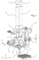
- FIG. 1 to 3 A first embodiment of a device according to the invention is shown. In most figures, a Cartesian coordinate system is shown in order to be able to identify the different spatial and movement directions. Figures 1 to 3 the individual components and their mutual assignment can be seen.
- the description begins at the lower end of the device and ends at its upper part and thus in the opposite direction to the movement of the accumulator cells 5 through the device.
- the lowermost part of the device according to the invention is a carriage 1, which carries a cell holder 3.
- the carriage 1 can be moved in the direction of the X-axis, the Y-axis and/or the Z-axis by linear drives (not shown).
- the upper part of the device can also be moved relative to the carriage 1.
- "Mixed forms” are also possible, which consist of one or two movement axes being assigned to the carriage 1 and two or one movement axes being assigned to the upper part of the device.
- Figure 1 The embodiment shown also requires only two axes of movement.
- the carriage 1 and with it the cell holder 3 is always positioned under a conveyor arranged in the upper part of the device in such a way that a free slot of the cell holder 3 is located below an optional conveyor shaft (not visible in the Figure 1 ) is located.
- FIG. 1 1 shows a battery cell 5 inserted into a slot at the top left of the cell holder 3. This occurs when the battery cell 5 is conveyed downwards from the conveyor device of the device according to the invention in the conveying direction indicated by an arrow (in the direction of the negative Y-axis) until the lower end of the battery cell 5 is pressed into the previously free slot of the cell holder 3. The battery cell is then slightly press-fitted into the slot and is thus fixed and secured against tipping.
- an (optional) rotary-driven half-shell 7 is provided, which is always rotated about its longitudinal axis in such a way that it prevents the accumulator cell 5 from tipping.
- Figure 1 In the position shown, a supporting wall or other abutment should be provided on the side of the accumulator cell 5 opposite the half-shell 7 This abutment, as well as the guides and linear drives, is shown in the diagram for reasons of clarity. Figure 1 not shown.
- the carriage 1 is controlled so that it moves one slot further. For example, in the direction of the negative Z-axis or in the direction of the negative X-axis. Then there is again a free slot below the conveyor device according to the invention.
- the rotatable half-shell 7 does not follow the feed movement of the carriage 1; it maintains its position. It is obvious that the same effect can also be achieved if the carriage 1 is stationary and the upper part of the device moves relative to the carriage.
- the first magazine 9 or the second magazine 11 is a flexible hose or a tube, the inner diameter of which is matched to the outer diameter of a battery cell 5 so that the battery cells 5 can be stacked with some play in the magazine 9, 11.
- Only one accumulator cell 5 is indicated in each of the magazines 9 and 11, respectively.
- the positive pole of the accumulator cell is located at the top.
- the positive pole of the accumulator cells 5 is located at the bottom. All accumulator cells in the first magazine and the second magazine 11 are aligned in the same direction. This is the pole-oriented filling of the magazines 9, 11, as already mentioned.
- the magazines 9 and 11 are arranged vertically. This means that gravity ensures that a battery cell 5 always reaches the exit of the first magazine 9 or the second magazine 11 as soon as a battery cell 5 has been removed from one of the magazines 9, 11.
- the exit of the first magazine 9 is in the Figure 1 visible. It is the free space below the lower end of the first magazine 9.
- the exit of the second magazine 11 is also designed and arranged below the second magazine 11 in a corresponding manner.
- a slider 13 and a linear drive 15 are provided to the left of the exit of the first magazine 9.
- the slider 13 and the linear drive 15 form a first feed device.
- the linear drive 15 When the linear drive 15 is actuated, it moves the slider 13 in the direction of the positive X-axis until the slider 13 has conveyed a battery cell 5 from the exit of the first magazine 9 into a feed area of the conveyor device.
- a mirror-symmetrical arrangement is located on the right side of magazine 11.
- the conveying device consists of a rotationally drivable conveying wheel 17 on each side of the accumulator cell 5 located in the intake area.
- the conveying wheels 17 can be driven, for example, by an electric motor 19.
- the conveying wheel 17 is preferably made of rubber or another elastic material with a high coefficient of static friction to ensure a good frictional connection between the conveying wheels 17 and the accumulator cell 5.
- this abutment is a second conveyor wheel 17, which is also rotatably driven. It can also simply rotate (without its own drive). It is also possible to design the abutment as a fixed rib whose longitudinal direction runs parallel to the Y-axis.
- the abutment prevents the accumulator cell 5 from deflecting (backward) when the conveyor wheel 17 presses against the cylindrical outer contour of the accumulator cell 5.
- a certain contact force between the drivable conveyor wheel 17 and the accumulator cell 5 is required to frictionally transfer the force required to convey and secure the accumulator cell 5 and its designated slot in the cell holder 3 from the conveyor wheel 17 to the accumulator cell 5.
- the rotary drive or electric motor 19 When the rotary drive or electric motor 19 is activated, it transmits its rotary movement (here via a gear and a flat or toothed belt) to the conveyor wheel 17, so that the latter rotates counterclockwise and thus moves the accumulator cell 5 out of the intake area of the conveyor in the conveying direction (ie downwards in the Figure 1 ) through an optional conveyor shaft) in the direction of the slot or cell holder 3.
- the production shaft is in the Figure 3 It is the section between the intake area of the conveyor and the rotating half-shell 7. In the Figure 3 There is an accumulator cell 5 in the conveyor shaft.
- the optional rotary drive conveyor wheel 17 on the opposite side of the accumulator cell 5 rotates in the opposite direction, so that the drive forces of both conveyor wheels are added.
- An alternative conveyor device consists of a ram and a linear drive arranged between the first magazine 9 and the second magazine 11 and above the feed area (not shown).
- the direction of movement of the ram is coaxial with the longitudinal axis of the accumulator cell 5 in the feed area of the conveyor device.
- this linear drive When this linear drive is activated, it pushes an accumulator cell 5 located in the intake area of the conveyor downwards (through the optional) conveyor shaft into a free slot in the cell holder 3.
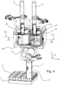
- FIG. 4 to 6 A second embodiment of a device according to the invention is shown. Many components are similar to those in the first embodiment; they have the same reference numerals. and it applies that with regard to the Figures 1 to 3 Said accordingly.
- FIG 4 the perspective is slightly different than the Figure 1 .
- the Figure 4 shows the conveyor device "from behind", so to speak, so that a rotary or swivel drive 21 for the rotatable half-shell 7 becomes visible.
- the half-shell 7 is in the Figure 4 largely concealed by a battery cell 5.
- Via a deflection gear (not shown in detail), the drive 21 can rotate the half-shell 7 about a rotational axis.
- the rotational axis of the half-shell runs coaxially with the longitudinal axis of the battery cell 5, which is to be secured against tipping by the half-shell 7.
- the slots of the cell holder 3 are clearly visible. They are arranged in rows and columns. A rechargeable battery cell 5 is inserted into each slot.
- the carriage 1 moves the cell holder 3 in the X and Z axes so that a free slot is located below the conveyor shaft of the conveyor device or coaxially and concentrically to the half-shell 7. As already explained, the relative movement of the carriage 1, or cell holder 3, and the upper part of the device is important.
- This free slot is then populated by transporting a battery cell 5 from the feed area into the free slot of the cell holder 3 by means of the conveyor device.
- first magazine and the second magazine are also arranged as a hose or tube that runs parallel to each other and is aligned vertically.
- each of the feed devices has a rotatably driven transport roller 23 with at least one groove 25.
- the transport movement is achieved by rotating the transport rollers.
- the transport rollers 23 are each surrounded by a guide wall 27.
- the guide walls 27 are curved and arranged concentrically to the axis of rotation of the transport rollers 23.
- the stop 29 is stationary, i.e., it does not rotate with the transport roller 23. It ends before the intake area of the conveyor device.
- the transport roller 23 is rotated approximately 120° counterclockwise.
- the drives 28 of the transport rollers 23 are in the Figure 6 clearly visible. They can be designed as stepper motors.
- the groove 25 conveys or transports a battery cell 5 from the exit of the first magazine 9 into the intake area of the conveyor. The same applies accordingly to the transport of a battery cell 5 from the exit of the second magazine 11 into the intake area of the conveyor.
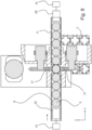
- FIG 5 A horizontal section through the transport rollers 23 is shown, which illustrates the functioning of these conveyor devices.
- the first magazine 9 and the second magazine 11 are represented by a broken circular line.
- Figure 5 the left transport roller 23 is positioned so that a groove 25 is directly below the first magazine 9 and another groove 25 and the the accumulator cell 5 located therein is located in the catchment area of the conveyor device.
- a circular recess 24 is formed on the transport rollers 23 between each two grooves 25. In this embodiment, their spacing is also 120°.
- the function of the circular recesses 24 can be seen from the Figure 5
- the right-hand transport roller 23 prevents the accumulator cell 5 from falling out of the groove 25 in the intake area of the conveyor.
- the intake area is located between the rotational axes of the transport rollers 23.
- a guide wall 27 prevents the accumulator cell 5 from falling out of the groove 25.
- the guide walls 27 end before the intake area of the conveyor.
- the guide walls 27 are arranged concentrically to the transport rollers 23. In the left part of the Figure 5 this is clearly visible.
- the rotational positions of the transport rollers 23 are coordinated so that a transport roller 23 Accumulator cell 5 is transported from the exit of a magazine 9, 11 into the feed area (in the Figure 5 this is the left transport roller 23).
- the other transport roller 23 is then brought into such a rotational position that a circular recess 24 is located in the intake area of the conveyor device (in the Figure 5 This is the right transport roller 23).
- the circular recess 24 of the right transport roller in the feed area of the conveyor supports the accumulator cell 5 fed by the left transport roller
- a distance between the rotational axes of the transport rollers 23 is designated by "S".
- a distance between the axis of rotation of a transport roller 23 and the lowest point of the circular arc-shaped recess 24 is designated S VT .
- the diameter of an accumulator cell 5 is designated "D A ".
- a distance between the axis of rotation of a transport roller 23 and the lowest point of the groove 25 is designated S AK .
- the radius R FW of the guide wall 27 is dimensioned such that, starting from the distance S AK, the diameter D A of a battery cell 5 is added. It goes without saying that a certain amount of play, for example, of 0.5 mm to 2 mm, is provided so that the battery cell 5 is not clamped between the groove 25 and the guide wall 27.
- the accumulator cell 5 in the intake area of the conveyor device can now be transported downwards through the conveyor shaft to the cell holder (not shown) by a conveyor device, for example with two driven conveyor wheels 17, as in the first embodiment.
- the conveying device can also be implemented using a ram and a linear drive (neither shown). Both are arranged above the accumulator cell 5 and thus also above the drawing plane.
- the linear drive drives the ram downward, which in turn pushes the accumulator cell 5 downward through the conveyor shaft into its assigned slot in the cell holder.
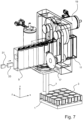
- the magazines 9 and 11 are designed as hoses or rectangular tubes that extend horizontally.
- the first magazine 9 extends to the left of the feed area of the conveyor device.
- the second magazine 11 is arranged to the right of the feed area.
- the dimensions of the magazines 9 and 11, designed as rectangular tubes, are coordinated with the length and diameter of the battery cells. This means that the battery cells can be temporarily stored vertically next to one another in the magazines 9 and 11 respectively.
- the positive poles of the battery cells 5 are arranged at the top.
- the positive poles of the battery cells 5 are arranged at the bottom. This means that here too, all battery cells 5 in a magazine are aligned the same (pole-oriented filling).
- the battery cells of the first magazine and the second magazine are aligned in opposite directions.
- the feeding devices are not shown in this embodiment or are shown only in a very simplified manner. They can be implemented, for example, by a punch 33 and a linear drive 31, which is located to the side of the magazines 9 and 11, respectively.
- a punch 33 and a linear drive 31 which is located to the side of the magazines 9 and 11, respectively.
- a first feed device is shown schematically and in a highly simplified manner.
- the punch has the reference numeral 33 and the linear drive has the reference numeral 31.
Landscapes
- Engineering & Computer Science (AREA)
- Mechanical Engineering (AREA)
- Chemical & Material Sciences (AREA)
- Chemical Kinetics & Catalysis (AREA)
- Electrochemistry (AREA)
- General Chemical & Material Sciences (AREA)
- Battery Mounting, Suspending (AREA)
- Specific Conveyance Elements (AREA)
Applications Claiming Priority (1)
| Application Number | Priority Date | Filing Date | Title |
|---|---|---|---|
| DE102021113697.0A DE102021113697A1 (de) | 2021-05-27 | 2021-05-27 | Vorrichtung zum Bestücken von Zellhaltern von Akkumulatoren |
Publications (3)
| Publication Number | Publication Date |
|---|---|
| EP4095995A1 EP4095995A1 (de) | 2022-11-30 |
| EP4095995B1 true EP4095995B1 (de) | 2025-06-18 |
| EP4095995C0 EP4095995C0 (de) | 2025-06-18 |
Family
ID=82214403
Family Applications (1)
| Application Number | Title | Priority Date | Filing Date |
|---|---|---|---|
| EP22174028.5A Active EP4095995B1 (de) | 2021-05-27 | 2022-05-18 | Vorrichtung zum bestücken von zellhaltern von akkumulatoren |
Country Status (3)
| Country | Link |
|---|---|
| EP (1) | EP4095995B1 (pl) |
| DE (1) | DE102021113697A1 (pl) |
| PL (1) | PL4095995T3 (pl) |
Families Citing this family (1)
| Publication number | Priority date | Publication date | Assignee | Title |
|---|---|---|---|---|
| DE102023128811A1 (de) * | 2023-10-19 | 2025-04-24 | Teamtechnik Maschinen Und Anlagen Gmbh | Vorrichtung zum Handhaben von Bauteilen |
Family Cites Families (12)
| Publication number | Priority date | Publication date | Assignee | Title |
|---|---|---|---|---|
| DE3509802A1 (de) * | 1985-03-19 | 1986-09-25 | Heckler & Koch Gmbh, 7238 Oberndorf | Verfahren und vorrichtung zum handhaben von werkstuecken |
| US7584589B2 (en) * | 2007-03-09 | 2009-09-08 | Georgia-Pacific Consumer Products Lp | Robotic multi-product case-packing system |
| DE102013207536B4 (de) * | 2013-04-25 | 2019-02-07 | Lisa Dräxlmaier GmbH | Zellblock mit Zellfixierung für eine Batterie und Verfahren zum Bestücken eines Zellblocks |
| US9368827B2 (en) * | 2013-08-21 | 2016-06-14 | GM Global Technology Operations LLC | Horizontal high speed stacking for batteries with prismatic cans |
| DE102016006176A1 (de) * | 2015-05-27 | 2016-12-01 | Bert Jeschke | Bearbeitungsvorrichtung und -verfahren für die Verwertung elektrochemischer Energiespeicher |
| CN105858169A (zh) * | 2016-06-15 | 2016-08-17 | 江苏正昀新能源投资有限公司 | 一种新型圆柱形锂电池pack装配转盒机 |
| CN107093761B (zh) * | 2017-03-31 | 2019-04-16 | 宁波利维能储能系统有限公司 | 电池模块生产流程工艺 |
| AT519968B1 (de) * | 2017-06-08 | 2018-12-15 | Avl List Gmbh | Bestückungsverfahren für batteriezellen und manipulationseinrichtung hierfür |
| CN108899589B (zh) * | 2018-07-13 | 2020-04-14 | 广东六缘智能装备科技有限公司 | 一种锂电池组自动组装机 |
| CN111824501A (zh) * | 2020-07-17 | 2020-10-27 | 惠州金旺达电子有限公司 | 一种圆柱形锂电池装配转盒机 |
| CN112372288A (zh) * | 2020-11-03 | 2021-02-19 | 张群 | 一种锂电池电芯装入外壳设备 |
| CN112599835A (zh) * | 2020-12-15 | 2021-04-02 | 深圳市汇鼎智能制造技术有限公司 | 一种电芯智能制造系统及电芯智能制造方法 |
-
2021
- 2021-05-27 DE DE102021113697.0A patent/DE102021113697A1/de active Pending
-
2022
- 2022-05-18 EP EP22174028.5A patent/EP4095995B1/de active Active
- 2022-05-18 PL PL22174028.5T patent/PL4095995T3/pl unknown
Also Published As
| Publication number | Publication date |
|---|---|
| DE102021113697A1 (de) | 2022-12-01 |
| PL4095995T3 (pl) | 2025-10-13 |
| EP4095995A1 (de) | 2022-11-30 |
| EP4095995C0 (de) | 2025-06-18 |
Similar Documents
| Publication | Publication Date | Title |
|---|---|---|
| DE60013438T2 (de) | Zuführvorrichtung für eine tubenfüllmaschine | |
| EP2035283A1 (de) | Vorrichtung zur behandlung von flexiblen schlauchartigen gebilden mit wenigstens einer öffnung | |
| DE69508976T2 (de) | Vorrichtung zum Zuführen von Rollen zu einer Verwendungsmaschine | |
| EP2492041A1 (de) | Flexible Entladevorrichtung für eine Rohrbearbeitungsvorrichtung ; Stützschlitten für die Aufnahme und Unterstützung eines Rohres ; Verfahren zum Entladen eine srohres unter Verwendung einer solchen Entladungvorrichtung | |
| WO1998013907A1 (de) | Endloskabelbearbeitungsvorrichtung | |
| DE2929851C2 (pl) | ||
| DE102018213800A1 (de) | Transportvorrichtung mit Transportrechen und Gegenrechen | |
| EP2605987B1 (de) | Non-stop-einrichtung | |
| DE102007015046B3 (de) | Stanzvorrichtung und Stanzverfahren | |
| EP3823751A1 (de) | Transportsystem | |
| EP4095995B1 (de) | Vorrichtung zum bestücken von zellhaltern von akkumulatoren | |
| DE1014060B (de) | Vorrichtung zum Einfuehren von rundem Halbzeug, z.B. Stangen in Bearbeitungsmaschinen mit axialer Vorschubbewegung, z.B. Ziehbaenke | |
| EP2307264A1 (de) | Transporteinrichtung | |
| EP2532456B1 (de) | Biegemaschine und Biegewerkzeug | |
| EP2944390B1 (de) | Biegewerkzeug sowie verfahren zum werkzeugwechsel | |
| DE3221620A1 (de) | Vorrichtung zum anbringen von komponenten | |
| DE2210983A1 (de) | Verfahren und Vorrichtung zur Montage von Einfach- und Mehrfach-Antriebsrollenketten | |
| EP1704941B1 (de) | Positioniereinrichtung zum Positionieren von Querdrähten für eine Gitterschweissmaschine und Verfahren zum Einlegen von Querdrähten in eine Gitterschweissmaschine | |
| WO2022161563A1 (de) | Vorrichtung zum einbringen von wälzkörpern in lager | |
| DE3018628C2 (de) | Vorrichtung zum automatischen Aufwickeln von Stranggut, insbesondere von Draht | |
| DE102005002532A1 (de) | Vorrichtung und Verfahren zum automatisierten und zeitgleichen Bereitstellen und Wechseln von mindestens zwei Rollen aus Papierbahnen oder dergleichen für einen nachgeordneten Formatschneider | |
| DE3236060C2 (pl) | ||
| DE1214137B (de) | Vorrichtung zum Herstellen und Fuellen von Huellen mit Bodenfaltung an einer Zigaretten-Verpackungsmaschine | |
| DE3632691C2 (pl) | ||
| DE69703978T2 (de) | Vorrichtung zum regeln der grösse eines werkzeugmaschinen-blechhalters |
Legal Events
| Date | Code | Title | Description |
|---|---|---|---|
| PUAI | Public reference made under article 153(3) epc to a published international application that has entered the european phase |
Free format text: ORIGINAL CODE: 0009012 |
|
| STAA | Information on the status of an ep patent application or granted ep patent |
Free format text: STATUS: THE APPLICATION HAS BEEN PUBLISHED |
|
| AK | Designated contracting states |
Kind code of ref document: A1 Designated state(s): AL AT BE BG CH CY CZ DE DK EE ES FI FR GB GR HR HU IE IS IT LI LT LU LV MC MK MT NL NO PL PT RO RS SE SI SK SM TR |
|
| STAA | Information on the status of an ep patent application or granted ep patent |
Free format text: STATUS: REQUEST FOR EXAMINATION WAS MADE |
|
| 17P | Request for examination filed |
Effective date: 20230530 |
|
| RBV | Designated contracting states (corrected) |
Designated state(s): AL AT BE BG CH CY CZ DE DK EE ES FI FR GB GR HR HU IE IS IT LI LT LU LV MC MK MT NL NO PL PT RO RS SE SI SK SM TR |
|
| STAA | Information on the status of an ep patent application or granted ep patent |
Free format text: STATUS: EXAMINATION IS IN PROGRESS |
|
| 17Q | First examination report despatched |
Effective date: 20240712 |
|
| GRAP | Despatch of communication of intention to grant a patent |
Free format text: ORIGINAL CODE: EPIDOSNIGR1 |
|
| STAA | Information on the status of an ep patent application or granted ep patent |
Free format text: STATUS: GRANT OF PATENT IS INTENDED |
|
| RIC1 | Information provided on ipc code assigned before grant |
Ipc: H01M 50/213 20210101ALN20250122BHEP Ipc: B65B 35/54 20060101ALI20250122BHEP Ipc: B65B 35/04 20060101ALI20250122BHEP Ipc: B65B 5/12 20060101ALI20250122BHEP Ipc: H01M 50/244 20210101ALI20250122BHEP Ipc: H01M 50/207 20210101ALI20250122BHEP Ipc: H01M 50/20 20210101AFI20250122BHEP |
|
| INTG | Intention to grant announced |
Effective date: 20250131 |
|
| GRAS | Grant fee paid |
Free format text: ORIGINAL CODE: EPIDOSNIGR3 |
|
| GRAA | (expected) grant |
Free format text: ORIGINAL CODE: 0009210 |
|
| STAA | Information on the status of an ep patent application or granted ep patent |
Free format text: STATUS: THE PATENT HAS BEEN GRANTED |
|
| AK | Designated contracting states |
Kind code of ref document: B1 Designated state(s): AL AT BE BG CH CY CZ DE DK EE ES FI FR GB GR HR HU IE IS IT LI LT LU LV MC MK MT NL NO PL PT RO RS SE SI SK SM TR |
|
| REG | Reference to a national code |
Ref country code: GB Ref legal event code: FG4D Free format text: NOT ENGLISH |
|
| REG | Reference to a national code |
Ref country code: CH Ref legal event code: EP |
|
| REG | Reference to a national code |
Ref country code: DE Ref legal event code: R096 Ref document number: 502022004294 Country of ref document: DE |
|
| REG | Reference to a national code |
Ref country code: CH Ref legal event code: EP |
|
| REG | Reference to a national code |
Ref country code: IE Ref legal event code: FG4D Free format text: LANGUAGE OF EP DOCUMENT: GERMAN |
|
| U01 | Request for unitary effect filed |
Effective date: 20250714 |
|
| U07 | Unitary effect registered |
Designated state(s): AT BE BG DE DK EE FI FR IT LT LU LV MT NL PT RO SE SI Effective date: 20250721 |
|
| PG25 | Lapsed in a contracting state [announced via postgrant information from national office to epo] |
Ref country code: NO Free format text: LAPSE BECAUSE OF FAILURE TO SUBMIT A TRANSLATION OF THE DESCRIPTION OR TO PAY THE FEE WITHIN THE PRESCRIBED TIME-LIMIT Effective date: 20250918 Ref country code: GR Free format text: LAPSE BECAUSE OF FAILURE TO SUBMIT A TRANSLATION OF THE DESCRIPTION OR TO PAY THE FEE WITHIN THE PRESCRIBED TIME-LIMIT Effective date: 20250919 |
|
| PG25 | Lapsed in a contracting state [announced via postgrant information from national office to epo] |
Ref country code: HR Free format text: LAPSE BECAUSE OF FAILURE TO SUBMIT A TRANSLATION OF THE DESCRIPTION OR TO PAY THE FEE WITHIN THE PRESCRIBED TIME-LIMIT Effective date: 20250618 |
|
| PG25 | Lapsed in a contracting state [announced via postgrant information from national office to epo] |
Ref country code: RS Free format text: LAPSE BECAUSE OF FAILURE TO SUBMIT A TRANSLATION OF THE DESCRIPTION OR TO PAY THE FEE WITHIN THE PRESCRIBED TIME-LIMIT Effective date: 20250918 |
|
| PG25 | Lapsed in a contracting state [announced via postgrant information from national office to epo] |
Ref country code: IS Free format text: LAPSE BECAUSE OF FAILURE TO SUBMIT A TRANSLATION OF THE DESCRIPTION OR TO PAY THE FEE WITHIN THE PRESCRIBED TIME-LIMIT Effective date: 20251018 |
|
| PG25 | Lapsed in a contracting state [announced via postgrant information from national office to epo] |
Ref country code: SM Free format text: LAPSE BECAUSE OF FAILURE TO SUBMIT A TRANSLATION OF THE DESCRIPTION OR TO PAY THE FEE WITHIN THE PRESCRIBED TIME-LIMIT Effective date: 20250618 |
|
| PG25 | Lapsed in a contracting state [announced via postgrant information from national office to epo] |
Ref country code: CZ Free format text: LAPSE BECAUSE OF FAILURE TO SUBMIT A TRANSLATION OF THE DESCRIPTION OR TO PAY THE FEE WITHIN THE PRESCRIBED TIME-LIMIT Effective date: 20250618 |
|
| PG25 | Lapsed in a contracting state [announced via postgrant information from national office to epo] |
Ref country code: SK Free format text: LAPSE BECAUSE OF FAILURE TO SUBMIT A TRANSLATION OF THE DESCRIPTION OR TO PAY THE FEE WITHIN THE PRESCRIBED TIME-LIMIT Effective date: 20250618 |
|
| PG25 | Lapsed in a contracting state [announced via postgrant information from national office to epo] |
Ref country code: ES Free format text: LAPSE BECAUSE OF FAILURE TO SUBMIT A TRANSLATION OF THE DESCRIPTION OR TO PAY THE FEE WITHIN THE PRESCRIBED TIME-LIMIT Effective date: 20250618 |
|
| PLBE | No opposition filed within time limit |
Free format text: ORIGINAL CODE: 0009261 |
|
| STAA | Information on the status of an ep patent application or granted ep patent |
Free format text: STATUS: NO OPPOSITION FILED WITHIN TIME LIMIT |
|
| U20 | Renewal fee for the european patent with unitary effect paid |
Year of fee payment: 5 Effective date: 20260326 |
|
| REG | Reference to a national code |
Ref country code: CH Ref legal event code: L10 Free format text: ST27 STATUS EVENT CODE: U-0-0-L10-L00 (AS PROVIDED BY THE NATIONAL OFFICE) Effective date: 20260430 |